HV390 Series Frequency Inverter. User Manual (Version: 3.1.14) - page 2
Chapter 4 Keyboard Operation
4.1 Keyboard introduce
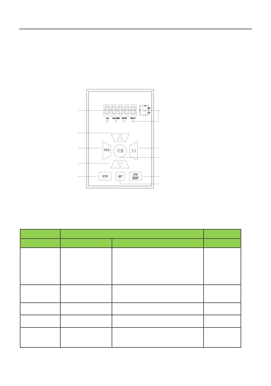
led monitor
LED monitoring indicator
increasing key
Programming key
shift key
enter key
decreasing key
running key
Stop / reset key
Multi-functional selection key
Figure 3 - 1 Keyboard(HV390−DP01)
4.2 Descriptions of Indicators
Indicator sign
name
Meanings
Indicator sign
name
Meanings
Color
off: Running command is given by
keyboard
Running command
on: Running command is given by terminal
LOCAL/REMOT
reference mode
red
operation
indicator
Flashing:Running command is given by host
computer
ON : running state
Running status
RUN
OFF : stop state
green
indicator
Flashing : stopping state
Positive and negative
ON : forward running
FWD/REV
red
indicator light
OFF : reverse running
ON : Fault condition
TUNE/TC
Tuning/Fault indicator
red
OFF : Normal conditio
ON : Current display parameter is running
Hz
Frequency indicator
red
frequency
28
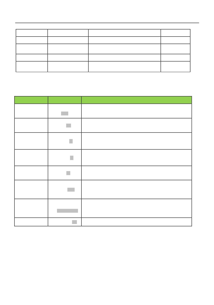
A
Current indicator
ON : Current display parameter is current
red
V
Voltage indicator
ON : Current display parameter is voltage
red
ON : Current display parameter is rotating
RPM(Hz+A)
Rotating speed
red
speed
S/M(A+V)
Time indicator
ON : Current display parameter is time
red
ON : Current display parameter is
%(Hz+V)
% indicator
red
percentage
4.3 Button description of Keyboard
Sign
Name
Function
1、Switch between program and other states, which includes
Programming key
PRG
parameters display and programming;
PRG
2、In menu status, press this key to return previous menu.
1、In program status, press this key to enter next menu.
OK
EnterOK
2、In menu level 3, press this key to save parameters value.
1、In first level menu, increase function code PX according to edit bit
Increase∧
2、In second level menu, increase the function code PX YZ data.
3、In third level menu ,Increase the function code data
1、In first level menu, decrease function code PX according to edit bit
Decrease∨
2、In second level menu, decrease the function PX YZ code data
3、In third level menu ,decrease the function code data
1、In third level menu ,use key >> to shift edit bit of the data
>>
Shift>>
2、In stop/run status, switch the panel display parameters such as
frequency, current and voltage.
1、When running command is given via operation panel, the key is used to
control the start of inverter.
RUN
Run KeyRUN
2、After setting the parameter auto tuning,start parameter auto tuning for
inverter startup
1、When running command is given via operation panel, the key is used to
STOP
Stop/Reset
control the stop of inverter.
KeySTOP/RESET
2、When the inverter has fault and has stopped, this key is used as
/RESET
RESET key to clear the fault alarm.
MF
Multi-functionMF
0:Nonfunction;1:forwardpoint running.;2:reverse
4.4 Keypad Operating Status
4.4.1 Initialization after power on
When the power is switched on, panel will start 5 seconds’ initiation process. During this process, LED
displays "8.8.8.8.” , and all LED indicators on the panel are in ON state
29
4.4.2 Stopping State
In stopping state, LED displays default parameters in flashing mode, and the unit indicator in right side
displays the unit of this parameters. In this state, all status indicators are OFF, press ►► key ,LED displays
fault code“n-xx”(xx=00-08),pressSET key to enter and view the parameter; press PRG key to exit; and
press ►► key to scroll through parameters in stopping state.
4.4.3 Running state
In stopping state, after receiving running command, the drive enters running state. The LED and unit
indicator display parameter and its unit respectively.
At this time, running status indicator is ON all the time. Press PRG key to enter programming menu and
view parameter value.
Press ►► key, LED displays running parameter “r-xx” (xx=00~14). Press SET key to enter and view
parameter value; press PRG key to exit this parameter menu; press ►► key to scroll through monitoring
parameters.
4.4.4 Fault alarm state
In stopping, running or programming state, correspondent fault information will be reported if fault is
detected. At this time, LED displays the fault code in flashing mode. When fault alarm occurs, press PRG
key to enter programming menu and look up the fault log.
When fault alarm occurs, the alarm picture is displayed, and the fault can be reset by press
STOP/RESET key. The drive restores to normal operation upon clearing the fault, and the fault code is
displayed again if the fault has not been cleared.
4.5 Panel Operation Method
4.5.1 Panel Operation Procedure
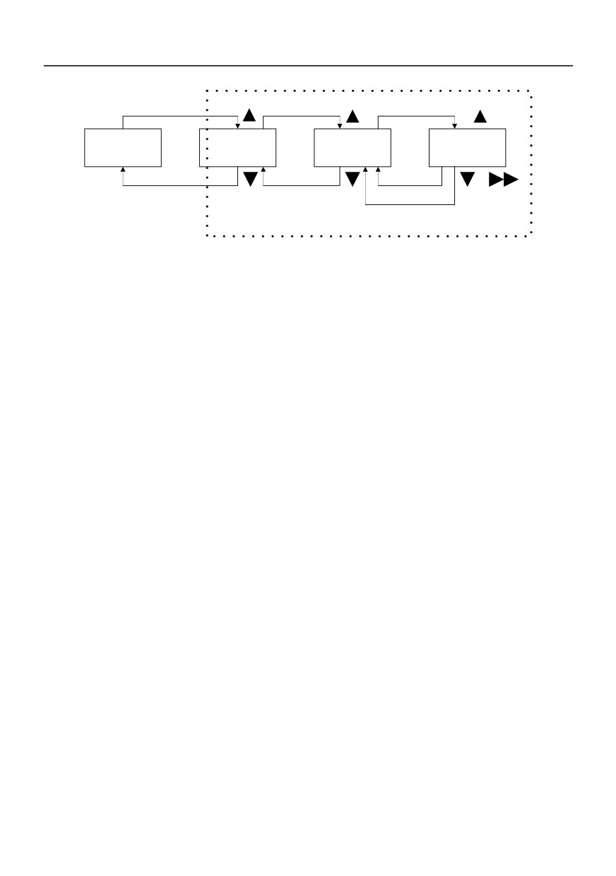
Parameter setting method via panel: through three-level menu, users can look up and modify
the function codes very easily.
Three level menu structure: function parameters (first level)→function codes(second level)→value of
function code(third level). Operation process is shown in Fig.4-1.
30
PRG
SET
SET
Stop/run
first level
second level
third level
PRG
PRG
PRG
function codes set
Fig.4-1 Menu Operation Procedure
In the third level menu, user can return second level menu by pressing PRG key or SET key. The
difference is: Parameter settings can be saved in control board if SETkey is pressed, then LED returns to
second level menu and shifts to next function code automatically; If user presses PRG key, LED returns to
second level menu directly, but the parameters can not be saved and stop at current function code.
4.5.2 Parameter setup
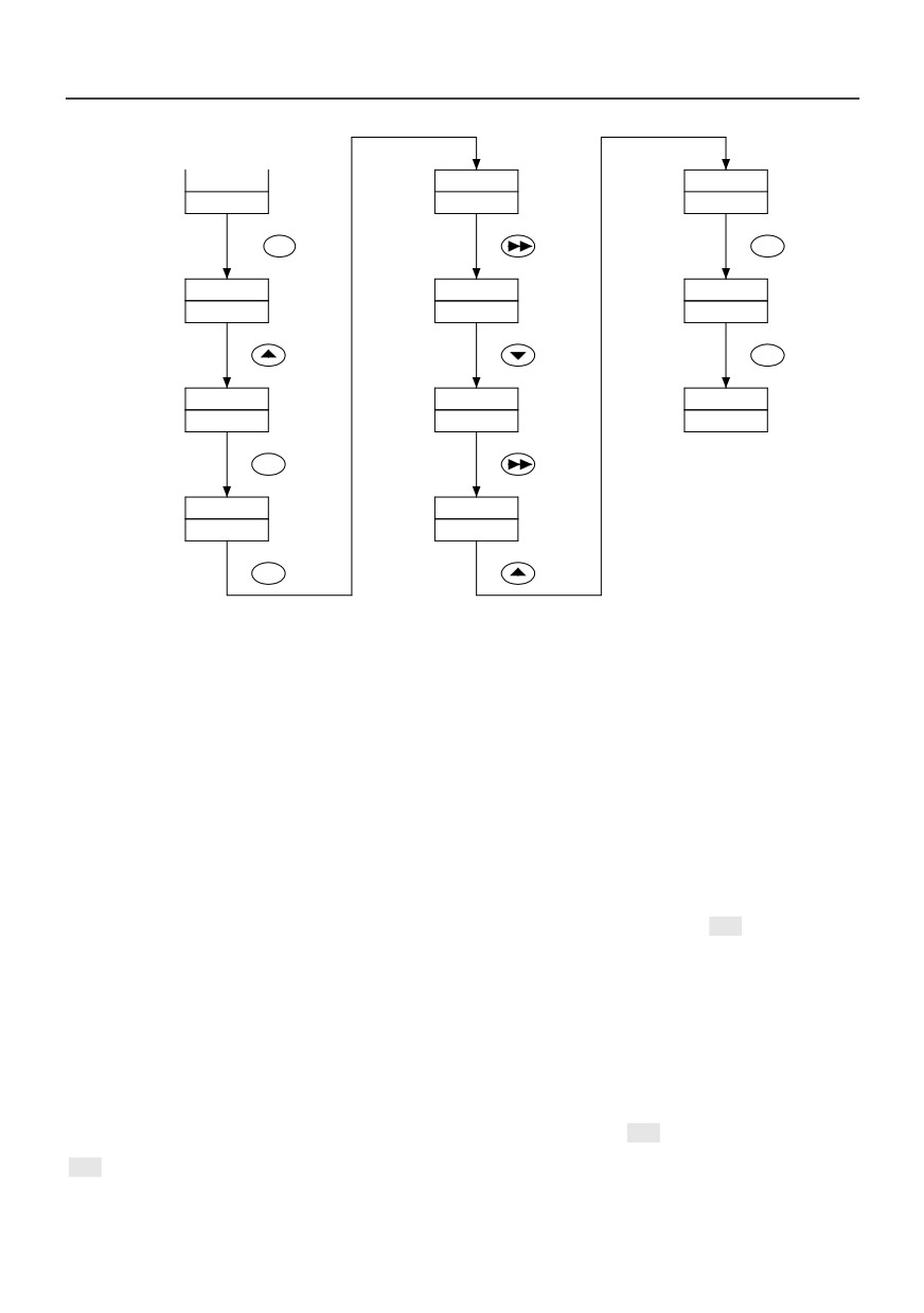
Setting parameters correctly is a premise for actualizing HV390’s performances. Parameter setting
method via panel will be introduced in the following part with rated power as an example (Change 18.5kW
into 7.5kW).
Operation process is shown in Fig.4-2. Press the SHIFT key with single direction shifting function to shift
the flashing bit of parameters (that is modification bit). After finishing the parameters setup, press the MENU
key twice to exit programing state.
31
stopping state
/ running state
50.00
018.5
007.5
Stop monitoring
0.4~999.9KW
0.4~999.9 KW
parameters
PRG
By two
SET
times
-P0-
018.5
P3.01
Basic
0.4~999.9KW
Motor rated
P0
parameters
voltage
By three
PRG
times
-P3-
008.5
50.00
motor
0.4~999.9KW
Stop monitoring
P3
parameters
parameters
stopping state
/ running state
SET
P3.00
008.5
0.4~999.9 KW
Motor rated power
SET
At a time
Fig 4-2 Procedure of parameter setup
4.6 Parameter Display
In stopping state or running state, various state parameters can be displayed by LED. The displayed
parameters can be decided by PH.00 ~ PH.01 and can be scrolled through by pressing the SHIFT key. The
following is an explanation for the parameters operation method in stopping and running state.
4.6.1 Switch of Parameter Display in Stopping State
In stopping state, the drive has 9 state parameters which can be scrolled by ►► key, they are:
frequency setting, external counting value, digital value input terminal state, digital value output terminal
state, panel potentiometer, analog input AI1, analog input AI2 and DC bus voltage. Please refer to the
explanation of PH.01.
The default value of PH.01 is "preset frequency". If PH.01 value is set to 2, default display parameter in
stopping state will be changed into "DC bus voltage".
User can look up other parameters during stopping state by pressing ►► key: Everytime you press
►► key, the next parameter in stopping state will be displayed.
32
4.6.2 Switch of the running parameters
In running state, maximum 15 running state parameters can be displayed by HV390 drive via ►► key.
4.7 Motor auto-tuning procedure
Before selecting vector control mode, user should input motor parameters correctly. HV390 drive can
get motor’s standard parameters according to the parameters on nameplate; In order to get better control
performance, you can control the drive to perform auto-tuning on the motor, so as to get accurate motor
parameters. Tuning is divided into static tuning and overall auto- tuning. If the motor and load cannot be
completely removed, p3.05 =1 shall be set for static tuning. The steps of tuning are as follows:
1.
Set P0.01= 0 to select panel running command control mode;
2.
According the motor’s name-plat,Set P3.00、P3.01、P3.02、P3.03、P3.04 parameter in proper order。
3.
Set P3.05=1,Slect static auto- tuning,Or set P3.05 = 2,Slect overall auto- tuning ,Press“SET”key。
4.
Press "run" and the keyboard displays "- id-" and starts tuning for 1-2 minutes.
5
After the tuning is finished, the machine is automatically stopped and the motor parameters are
automatically saved.
33
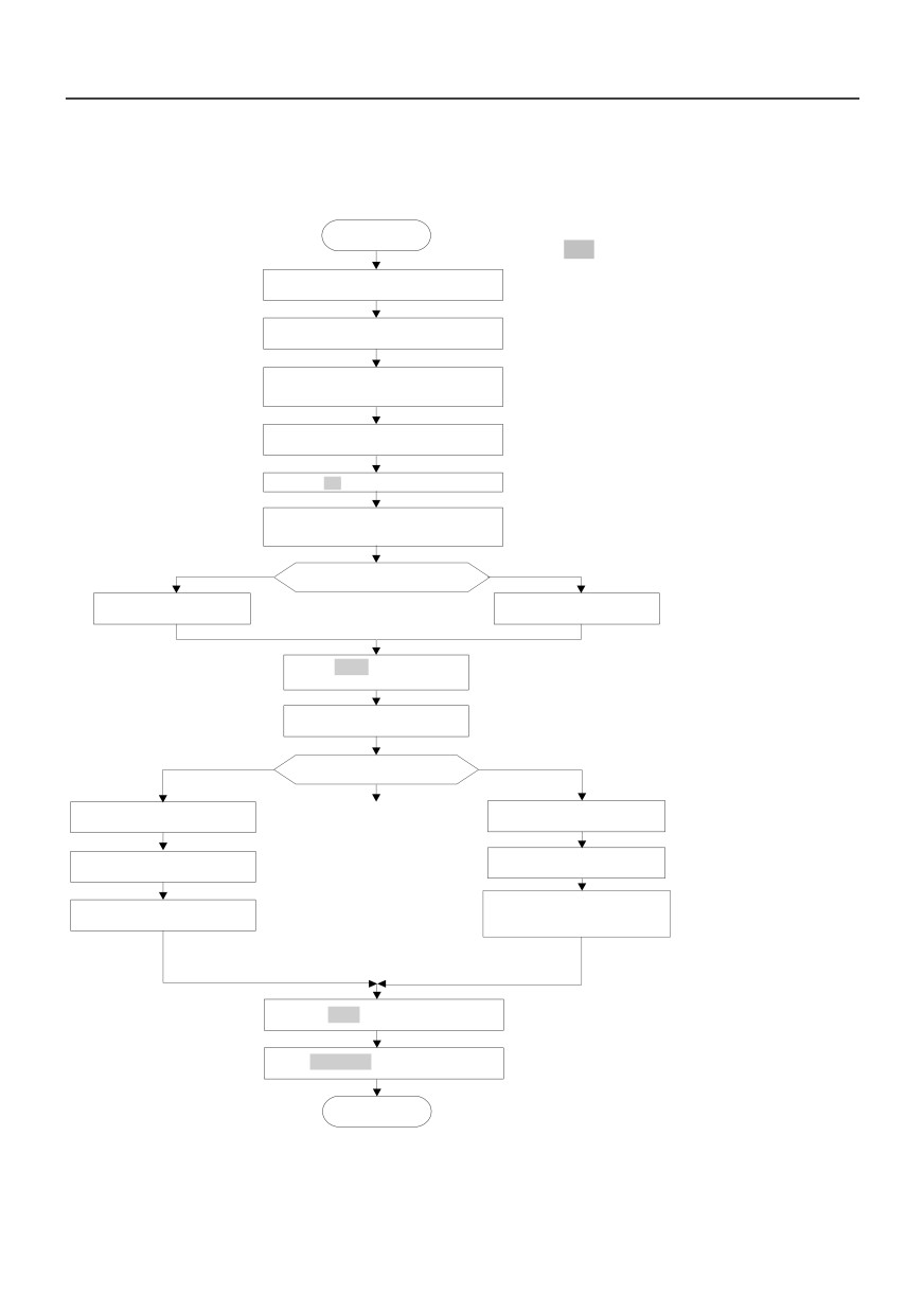
4.8 Running for the First Time
Please follow the procedures to run the inverter for the first time:
Start
Note:
◆If fault happens, please judge the fault
Before power up
, confirm the
wiring is correct
causes and clear the fault according to
7.1 Fault and alarm information list.
Setting P 0. 19 = 2
restore the
factory setting
◆If motor can without connecting the load
rotating auto tuning can be selected
Setting max output voltage P4.01 and motor
(P3.05=2),otherwise only static auto
basic frequency P4.02
according to motor
nameplate
tuning can be selected .When enabling
the auto tuning please ensure the motor is
Setting motor parameter P3.00
to
P3.04
according to motor nameplate
in standstill status .If over voltage or over
current happens in auto tuning process,
Press MFM key for jog operation
you can prolong the acceleration and
deceleration times of P0.16 and P0.17.
If motor running direction is wrong
, swap
any two phase wires of motor and then
power up
Static tuning or rotating tuning
Setting P 3. 05 = 1 to
Set ting P3.05 = 2 to
perform static auto
- tuning
perform rotating auto
- tuning
Press
RUN
key to start auto
tuning , after tuning stop auto
Setting running frequency P
0.11
V/F control or open loop vector
control?
Setting P0 . 02 to 0
open
Setting P 0. 02 to vector control
loop vector control
Refer to P5.06 and P5.07 for torque
Setting V/ F curve input P4. 00
input channel selection
Set speed limit P5.00~P5.05
during forward
/ reverse running
Setting torque boost P
4.07
process or limit the speed via
analog channel
Press
RUN
key to run the inverter
Press
STOP / RST
key to stop the inverter
END
34
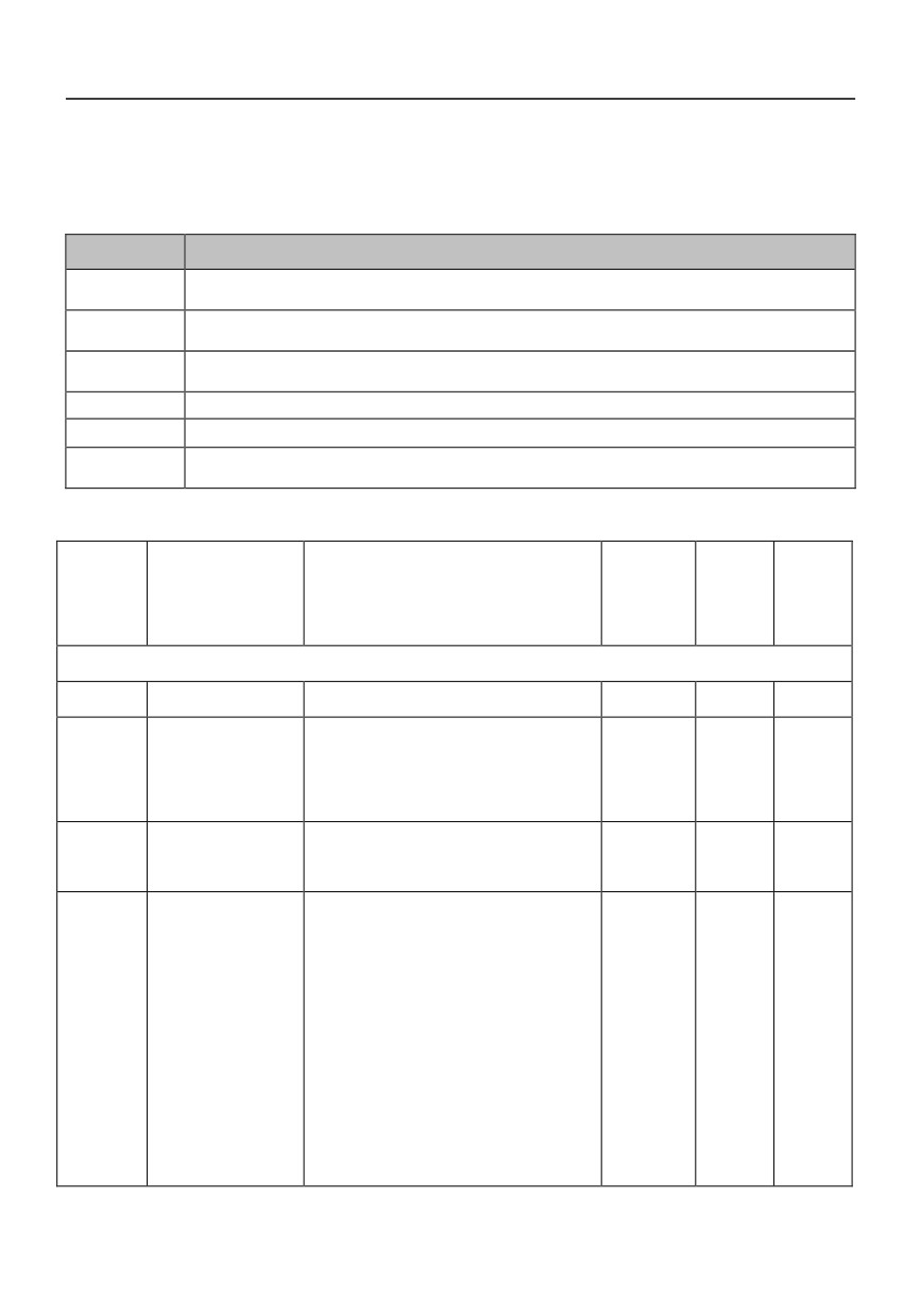
Chapter 5 List of Parameters
Meanings of Each Item in Function Code Parameter Table
Item
Meanings
Function code
The number of function code, such as P0.00
number
Function code
he name of function code, which explains the function code’s meanings.
name
Function code
Function code parameter setting list
selection
default value
Restore the settings of the function code after the product is delivered (see P0.19).
Order number
The order number of function code
#: This function code can be changed during operation; +: This function code can only be changed
Property
during stopping status; *: The setting of this function code is read-only and cannot be changed.
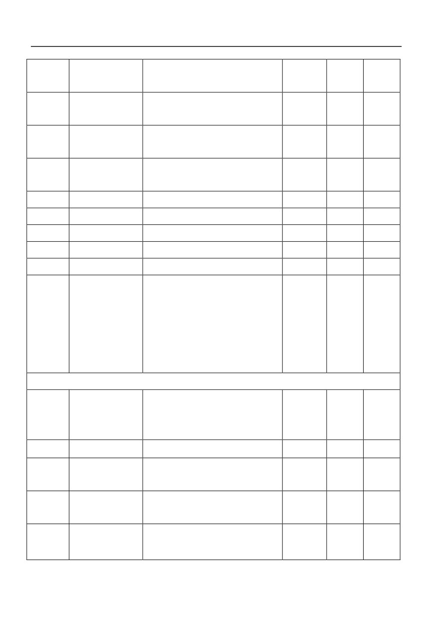
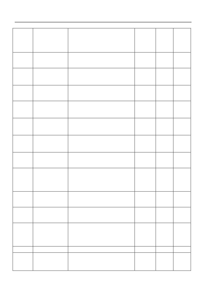
5.1 Function Parameter Table
Function
Name
Description
Factory
Order
Property
code
setting
numbe
r
P0 Group Basic parameter
P0.00
reserved
0
P0.01
Running command
0:keyboard operation
0
1
selection
1:External terminal
+
2:Commuincation
P0.02
Control mode
0:open loop vector control
1
2
+
1:V/F control
P0.03
Main Frequency
0: digital set via the keyboard
0
3
Source
1:Reserved
2:External analog signal AI1(0~10V)
3:External analog signal AI2(0~20mA)
4:up/down1 setting
+
5:up/down2 setting
6:Multistage speed
7:PID
8:Serial communication setting
35

9:Program run
P0.04
Main frequency
0.000-9.999
1.000
4
+
setting gain K1
P0.05
Zero frequency
0: Reserved
0
5
source of
1: Digital frequency of P0.11
multi-speed mode
2:External analog signal:AI1
+
3:External analog signal:AI2
4:Communication given
P0.06
Auxiliary frequency
0:External analog signal AI1(0~10V)
0
6
setting option
1:External analog signal AI2(0~20mA)
2:External analog signal AI1(0~10V)(+/-
polarity)
+
3:External analog signal AI2(0~20mA(+/-
polarity)
4:PID
5: Keyboard Increase and decrease key
P0.07
Auxiliary frequency
0:Relative maximum frequency
0
7
+
range selection
1:Relative primary given
P0.08
Auxiliary frequency
0-100%
100
8
+
setting range
P0.09
Setting Frequency
0:Main frequency
0
9
1:Auxiliary frequency
selection
2:Main frequency + Auxiliary frequency
3:Main frequency - Auxiliary frequency
4:switch between Main frequency and
Auxiliary frequency
5:switch between Main frequency and
(Main frequency + Auxiliary frequency)
+
6:switch between Main frequency and
(Main frequency - Auxiliary frequency)
7 : MAX ( Main frequency , Auxiliary
frequency)
8 : MIN ( Main frequency , Auxiliary
frequency)
9:Traverse operation
36
P0.10
UP/DOWN setting
0:Store
0
10
#
store selection
1:Not Store
P0.11
Digital frequency
0~600.0Hz
50.00
11
#
setting
P0.12
Rotating direction
0: FWD
0
12
+
(Keypad operation)
1: REV
P0.13
Maximum output
50.00~600.0 Hz
50.00
13
+
frequency
P0.14
High frequency limit
0.00 Hz ~ Maximum output frequency
50.00
14
+
P0.15
Low frequency limit
0.00Hz~ High frequency limit
0
15
+
P0.16
Acc time 1
0.1~3600.0s
20.0
16
#
P0.17
Dec time 1
0.1~3600.0s
20.0
17
#
P0.18
reserved
0
18
+
P0.19
Parameter
0: No operation
0
19
initialization
1: Clear fault information
2: Recover factory setting
+
3. Lock parameters
Note: After executing 1~2 steps, restores
to zero automatically.
P1 Group Auxiliary function parameters 1
0:Start from starting frequency
P1.00
Starting mode
0
20
1 : After DC braking, start by starting
+
frequency
P1.01
Starting frequency
0.50~20.00Hz
0.50
21
+
Hold time of Starting
P1.02
0.0~60.0s
0
22
+
Frequency
DC injection braking
P1.03
0.0~60.0s
0
23
+
time at start
P1.04
DC injection braking
0.0~100.0%( motor rated current)
0
24
+
current start
37
0: Dec-to-stop
P1.05
Stopping mode
0
25
1: Dec-to-stop + DC braking
+
2: Free run to stop
Initial frequency of
P1.06
0.00~20.00Hz
0
26
+
DC injection braking
DC injection braking
P1.07
0:No operation
0
27
+
time
0.1~60.0s
DC injection braking
P1.08
0.0~100.0%(motor rated current)
0
28
+
current
P1.09
Acc/Dec mode
0: Linear mode
0
29
+
selection
1:reserved
P1.10
Time of S curve’ s
10.0%~50.0%
20.0%
30
+
start part
P1.11
Time of S curve’ s
10.0%~80.0%
60.0%
31
+
rising part
P1.12
Restart after power
0: disabled
0
32
+
failure
1: enabled
P1.13
Delay time for
0.0~20.0s
2.0
33
restarting after
+
power failure
P1.14
dynamic braking
630-710
660
34
start voltage
P1.15
Rate of dynamic
0:No dynamic braking
90
35
#
braking
1~100%
P1.16
Action on frequency
0:dormancy
0
36
lower than lower
1:start, running at lower frequency limit
+
frequency limit
2:Stop
P1.17
MF key function
0:No operation; 1:reverse rotation
0
37
+
P1.18
Stop/reset Key
0:action on keypad control mode
0
38
function
1:action on both keypad and External
+
terminal
38
2:action on both keypad and
communication
P1.19
Fan control function
0:always run after power on
1
39
+
1: stop fan after inverter stop running
P2 Group Auxiliary function parameters 2
P2.00
Acc time 2
0.1~3600s
20.0
40
#
P2.01
Dec time 2
0.1~3600s
20.0
41
#
P2.02
Acc time 3
0.1~3600s
20.0
42
#
P2.03
Dec time 3
0.1~3600s
20.0
43
#
P2.04
Acc time 4
0.1~3600s
20.0
44
#
P2.05
Dec time 4
0.1~3600s
20.0
45
#
P2.06
Jog Acc time
0.1~20.0s
10.0
46
#
P2.07
Jog Dec time
0.1~20.0s
10.0
47
#
P2.08
Jog frequency
0.50~60.00Hz
5.00
48
#
P2.09
Multi-frequency 1
0.00~600.0 Hz
0.00
49
#
P2.10
Multi-frequency 2
0.00~600.0 Hz
0.00
50
#
P2.11
Multi-frequency 3
0.00~600.0 Hz
0.00
51
#
P2.12
Multi-frequency 4
0.00~600.0 Hz
0.00
52
#
P2.13
Multi-frequency 5
0.00~600.0 Hz
0.00
53
#
P2.14
Multi-frequency 6
0.00~600.0 Hz
0.00
54
#
P2.15
Multi-frequency 7
0.00~600.0 Hz
0.00
55
#
P2.16
Multi-frequency 8
0.00~600.0 Hz
0.00
56
#
P2.17
Multi-frequency 9
0.00~600.0 Hz
0.00
57
#
P2.18
Multi-frequency 10
0.00~600.0 Hz
0.00
58
#
P2.19
Multi-frequency 11
0.00~600.0 Hz
0.00
59
#
P2.20
Multi-frequency 12
0.00~600.0 Hz
0.00
60
#
P2.21
Multi-frequency 13
0.00~600.0 Hz
0.00
61
#
P2.22
Multi-frequency 14
0.00~600.0 Hz
0.00
62
#
P2.23
Multi-frequency 15
0.00~600.0 Hz
0.00
63
#
P2.24
Jump frequency 1
0.00~600.0 Hz
0.00
64
+
39
HV390 High Performance Vector Control Inverter
User Manual
P2.25
Jump frequency 2
0.00~600.0 Hz
0.00
65
+
P2.26
Jump frequency 3
0.00~600.0 Hz
0.00
66
+
P2.27
Jump frequency
0.00~20.00 Hz
0.00
67
+
range
P2.28
FWD/REV dead time
0.1~3600s
0.5
68
+
P2.29
REV prohibited
0: REV enabled
0
69
+
1: REV disabled
P2.30
Carrier frequency
2.0~12.0KHz
3.0
70
+
P2.31
Zero frequency
0.0~600.0Hz
0.00
71
+
threshold
P2.32
Zero frequency
0.0~600.0 Hz
0.00
72
+
hysteresis
P2.33
Droop control
0.00-10.00Hz
0.00
73
+
P3 Group motor parameters
P3.00
Motor rated power
0.4~999.9KW
Drive’s
74
rated
+
power
P3.01
Motor rated voltage
0~440V
380V
75
+
P3.02
Motor rated current
0.1~999.9A
Drive’s
76
rated
+
power
P3.03
Motor rated
1.00~400.0Hz
50.00
77
+
frequency
P3.04
Motor rated speed
1~9999RPM
1440
78
+
P3.05
Motor auto-tuning
0:No operation
0
79
1:static auto tuning
+
2:overall auto- tuning
P3.06
Stator resistance
0.001-20.00%
Motor
80
+
parameter
P3.07
Rotor resistance
0.001-20.00%
Motor
81
+
40
parameter
P3.08
Self inductance
1.000-9.999
Motor
82
+
parameter
P3.09
Leakage inductance
0.001-1.000
Motor
83
+
parameter
P3.10
Exciting current with
0.0~999.9A
Motor
84
+
no load
parameter
P3.11
reserved
85
+
P4Group V/F control
P4.00
0: Linear V/F
0
86
1: Square V/F
V/F control mode
2: 1.5 times torque
+
3: 1.2 times torque
4: User defined V/F
P4.01
Base voltage
0~440V
380
87
+
P4.02
Base frequency
10.00~600.0 Hz
50.00
88
+
P4.03
Intermediate voltage
0~P4.04
32
89
+
1
P4.04
Intermediate voltage
P4.03~100%
50
90
+
2
P4.05
Intermediate
0~P4.06
16.00
91
+
frequency 1
P4.06
Intermediate
P4.05~400.0Hz
25.00
92
+
frequency 2
P4.07
Torque boost
0.0~20.0%
(base voltage)
3.0
93
+
P4.08
Slip compensation
0.0~10.0%( rated speed)
0.00
94
+
P4.09
AVR function
0: disabled
0
95
+
1: enabled
P5 Group VC control
P5.00
ASR proportional
0.000~6.000
2.000
96
+
41
gain 1
P5.01
ASR integration time
0.000~9.999
0.500
97
+
1
P5.02
ASR proportional
0.000~6.000
1.000
98
+
gain 2
P5.03
ASR integration time
0.000~9.999
1.000
99
+
2
P5.04
ASR switching
00.00~99.99Hz
5.00
100
+
frequency
P5.05
Slip compensation
50.0~200.0%
100.0
101
+
gain
P5.06
Driving torque limit
0~200.0%(motor rated current)
150.0
102
+
P5.07
Braking torque limit
0~200.0%(motor rated current)
150.0
103
+
P5.08
reserved
104
+
P5.09
reserved
105
+
P5.10
reserved
106
+
P6 Group I/O parameters
P6.00
FWD/REV mode
0: Two-line operation mode 1
0
107
1: Two-line operation mode 2
+
2: 3-line operation mode 1
3: 3-line operation mode 2
P6.01
Up/down rate
0.10~99.99Hz/s
1.00
108
#
P6.02
Definition of input
0 :No function
1
109
+
terminal X1
1: FWD
P6.03
Definition of input
2: REV
2
110
+
terminal X2
3: External reset
P6.04
Definition of input
4: Jog FWD
3
111
+
terminal X3
5: Jog REV
P6.05
Definition of input
6: Multi-frequency 1
4
112
+
terminal X4
7: Multi-frequency 2
P6.06
Definition of input
8: Multi-frequency 3
5
113
+
42
HV390 High Performance Vector Control Inverter
User Manual
terminal X5
9: Multi-frequency 4
10: Terminals for selecting Acc/Dec time 1
11: Terminals for selecting Acc/Dec time 2
12: Normally open terminal for inputting
external fault
13: Normally close terminal for inputting
external fault
14: Frequency increase command
15: Frequency decrease command
16: Free run to stop
17: Three-wire control
18: switch of speed given mode
19:Reset terminal for program operation
20: Start traverse operation
21:pause traverse operation
22:DC braking command
23:Acc/Dec disabled command
24:switch between panel control mode and
external terminal control mode
25:switch between panel control mode and
communication control mode
26: Counter trig signal
27: Counter reset signal
28: PID dormancy waking up
29:switch between PID positive mode and
negative mode
30:emergence stop
P6.07
Terminal filter times
1-100
10
114
P6.08
Operation protection
0::protect
0
115
of power on terminal
1:no protect
P6.09
Programmable relay
0: No function
17
116
+
43
1
1: Drive ready
P6.10
Output terminal Y1
2: Drive running signal 1
1
117
+
definition
3: Drive running signal 2
4: Frequency arriving signal
5: Frequency detection threshold 1
6: Frequency detection threshold 2
7: High limit frequency arriving
8: Low limit frequency arriving
9: Overload signal
10: Over voltage stall
11: Over current stall
12: External stopping command
13: Preset counting value arriving
14: Specified counting value arriving
15: Low voltage lockup signal
16: Overload pre-alarm
17: Drive failure signal
18: Zero speed running
19:end signal of stage of program
operation
20:end signal of cycle of program
operation
P6.11
Frequency arriving
0.00~10.00Hz
0.00
118
#
width
P6.12
FDT1 level
0.00~600.0 Hz
50.00
119
#
P6.13
FDT1 lag
0.00~10.00Hz
0.00
120
#
P6.14
FDT2 level
0.00~600.0 Hz
25.00
121
#
P6.15
FDT2 lag
0.00~10.00Hz
0.00
122
#
P6.16
Preset value arriving
0~9999
0
123
+
P6.17
Specified value
0~9999
0
124
+
arriving
44
P6.18
Terminal logic
0~255
0
125
+
P7 Group Analog input terminal
P7.00
AI1 Filter time
0.05~5.00s
0.50
126
#
P7.01
Minimum AI1
0.0~100.0%
0.0
127
#
P7.02
Frequency
0.00~100.0%
(Maximum output
0.00
128
corresponding to
frequency)
#
P7.01
P7.03
Maximum AI1
0.0~100.0%
100.0
129
#
P7.04
Frequency
0.00~100.0%
(Maximum output
100.0
130
corresponding to
frequency)
#
P7.03
P7.05
AI2 filter time
0.05~5.00s
0.50
131
#
P7.06
Minimum AI2
0.0~100.0%
0.0
132
#
P7.07
Frequency
0.00~100.0%
(Maximum output
0.00
133
corresponding to
frequency)
#
P7.06
P7.08
Maximum AI2
0.0~100.0%
100.0
134
#
P7.09
Frequency
0.00~100.0%
(Maximum output
100.0
135
corresponding to
frequency)
#
F7.08
P7.10
FWD/REV dead time
0.0~10.0%
1.0
136
+
range
P7.11
Potentiometer input
0.05~5.00s
0.50
137
#
filter time
P7.12
Potentiometer input
0.0~100.0%
0.0
138
#
minimum
P7.13
Frequency
0.00~100.0%
(Maximum output
0.00
139
corresponding to
frequency)
#
F7.12
P7.14
Potentiometer input
0.0~100.0%
0.0
140
#
45
maximum
P7.15
Frequency
0.00~100.0%
(Maximum output
100.0
141
corresponding to
frequency)
#
F7.14
P8 Group Analog output terminal
P8.00
AO1 output selection
0: Running frequency
1
142
#
P8.01
reserved
1: Frequency setting
1
143
2: Output current(Ie)
3: Output voltage
4: Output torque
5: DC Bus Voltage
#
6: PI reference
7: PI feedback
8: AI1
9:AI2
P8.02
Minimum AO1
0.0~100.0%
0.0
144
#
P8.03
Minimum value
0.0~100.0%
0.0
145
corresponding to
#
F8.02
P8.04
Maximum AO1
0.0~100.0%
100.0
146
#
P8.05
Maximum value
0.0~100.0%
100.0
147
corresponding to
#
F8.04
P8.06
reserved
0.0~100.0%
0.0
148
#
P8.07
reserved
0.0~100.0%
0.0
149
#
P8.08
reserved
0.0~100.0%
100.0
150
#
P8.09
reserved
0.0~100.0%
100.0
151
#
P9 Group program operating parameters
P9.00
Program running
0: Single cycle (Stop after a single cycle)
0
152
function
1: Continuous cycle
+
2: Maintain the final value
46
P9.01
Run time unit
0:Second
0
153
+
1:Minute
P9.02
Stage 1 timing T1
0~3600.0
0
154
+
P9.03
Stage 2 timing T2
0~3600.0
0
155
+
P9.04
Stage 3 timing T3
0~3600.0
0
156
+
P9.05
Stage 4 timing T4
0~3600.0
0
157
+
P9.06
Stage 5 timing T5
0~3600.0
0
158
+
P9.07
Stage 6 timing T6
0~3600.0
0
159
+
P9.08
Stage 7 timing T7
0~3600.0
0
160
+
P9.09
Stage 8 timing T8
0~3600.0
0
161
+
P9.10
Stage 9 timing T9
0~3600.0
0
162
+
P9.11
Stage 10 timing T10
0~3600.0
0
163
+
P9.12
Stage 11 timing T11
0~3600.0
0
164
+
P9.13
Stage 12 timing T12
0~3600.0
0
165
+
P9.14
Stage 13 timing T13
0~3600.0
0
166
+
P9.15
Stage 14 timing T14
0~3600.0
0
167
+
P9.16
Stage 15 timing T15
0~3600.0
0
168
+
P9.17
T1 running mode
0:FWD,Acc/Dec time 1
0
169
+
P9.18
T2 running mode
1:FWD,Acc/Dec time 2
0
170
+
P9.19
T3 running mode
2:FWD,Acc/Dec time 3
0
171
+
P9.20
T4 running mode
3:FWD,Acc/Dec time 4
0
172
+
P9.21
T5 running mode
4:REV,Acc/Dec time 1
0
173
+
5:REV,Acc/Dec time 2
P9.22
T6 running mode
0
174
+
6:REV,Acc/Dec time 3
P9.23
T7 running mode
0
175
+
7:REV,Acc/Dec time 4
P9.24
T8 running mode
0
176
+
P9.25
T9 running mode
0
177
+
P9.26
T10 running mode
0
178
+
P9.27
T11 running mode
0
179
+
P9.28
T12 running mode
0
180
+
P9.29
T13 running mode
0
181
+
47
P9.30
T14 running mode
0
182
+
P9.31
T15 running mode
0
183
+
P9.32
Record function
0: Disabled
0
184
1:Record,not store after power off
+
2:Record,store after power off
PA Group PID parameters
PA.00
PID control
0: Positive characteristic
0
185
+
characteristic
1: Negative characteristic
PA.01
PID Reference
0: Panel Digital setting
0
186
selection
1: External analog signal AI1
+
2: External analog signal AI2
3:Communication
PA.02
Feedback channel
0: External analog signal AI1
0
187
+
selection
1: External analog signal AI2
PA.03
Digital setting of
0.00~10.00V
5.00
188
#
reference
PA.04
Minimum reference
0~100%
0
189
+
PA.05
Maximum reference
0~150%
100
190
+
PA.06
Minimum feedback
0~100%
0
191
+
PA.07
Maximum feedback
0~150%
100
192
+
PA.08
Proportional gain
0.00~10.00
1.00
193
#
PA.09
Integration time
0.01~99.99s
0.5
194
#
PA.10
Differential time
0.00,no differentiation
0
195
#
0.01~99.99s
PA.11
Sample cycle
0.01~99.99s
0.1
196
#
PA.12
Error limit
0.0~15.0%
0.0
197
#
PA.13
Level of abnormal
0~100%
50
198
#
feedback signal
PA.14
Detection time of
0:No detection
0.0
199
#
abnormal feedback
0.1~3600s
48
signal
PA.15
reserved
0
200
+
PA.16
PID Sleep control
0: No sleep function;
0
201
1: Internal waking up,
+
2. External input terminal
PA.17
Delay time of sleepin
0~3600s
0
202
+
PA.18
Sleeping frequency
0.00~400.0Hz
0.00
203
+
PA.19
Delay time of waking
0.0~60.0s
0.0
204
+
PA.20
Waking value
0.0~100.0%
100.0
205
+
Pb Group Traverse operation parameters
Pb.00
Traverse mode
0: Auto mode
0
206
+
1: Manual mode
Pb.01
Preset traverse
0.00~600.0Hz
0.00
207
#
frequency
Pb.02
Hold time of preset
0.0~3600s
0.0
208
#
traverse frequency
Pb.03
Preset central
0.00~600.0Hz
0.00
209
#
frequency
Pb.04
Travers amplitude
0.0~50.0% (Pb.03)
0.0
210
#
Pb.05
Step frequency
0.0~50.0%(Pb.04)
0.0
211
#
Pb.06
Traverse cycle
0.1~999.9s
10.00
212
#
Pb.07
Rise time of
0.0~100.0% (Pb.06)
50.0
213
#
triangular wave
PC Group 485 communication parameters
PC.00
Baud rate selection
0:1200BPS
3
214
1:2400BPS
2:4800BPS
+
3:9600BPS
4:19200BPS
5:38400BPS
PC.01
Data format
0:
8,N,2 for RTU
(MODBUS)
0
215
+
1:
8,E,1 for RTU
(MODBUS)
49
2:
8,O,1 for RTU
(MODBUS)
3:
7,N,2 for ASCII (MODBUS)
4:
7,E,1 for ASCII(MODBUS)
5:
7,O,1 for ASCII(MODBUS)
6:
8,N,1 free communication format
7:8,E,1 free communication format
8:
8,O,1 free communication format
9:Host mode, send current running
frequency
PC.02
Local address
1~32,0 is the broadcast address
1
216
+
PC.03
Communication
0, No detection
0
217
+
timeout detect
2.0~10.0s
PC.04
Response delay
2~1000ms
218
+
PC.05
EEROM Store
0:Store
0
219
+
selection
1:no store function
Pd Group Faults and protection parameters
Pd.00
Motor overload
0: No protection
1
220
protection mode
1: Common motor protection
+
2: Variable frequency motor protection
Pd.01
Motor overload
20.0~150.0%
100.0
221
+
protection factor
Pd.02
Over voltage stall
0: Disabled
1
222
+
selection
1: Enabled
Pd.03
Stall over voltage
115.0~150.0%(UDC)
120.0
223
+
point
Pd.04
Selection of
0: Detect at constant speed and alarm
0
224
overload pre-alarm
1: Detect all the time and alarm
+
detection
Pd.05
Overload detection
20.0~180.0%(Ie)
150.0
225
+
threshold
50
Pd.06
Overload pre-alarm
0.0~60.0s
2.0
226
+
delay
Pd.07
Auto current limiting
20.0~180.0%
150.0
227
+
threshold
Pd.08
Frequency decrease
0.00~99.99Hz/s
0.00
228
rate during current
+
limiting
Pd.09
Action mode of auto
0: Disabled
1
229
current limiting
1: Enabled during Acc/Dec, disabled at
constant speed
+
2: Enabled during Acc/Dec, enabled
at
constant speed
Pd.10
Auto reset
0:Disabled
0
230
+
1~5:Times of fault reset
Pd.11
Auto reset interval
2.0~20.0s
2.0
231
+
Pd.12
Relay action in Auto
0:No action
0
232
reset
1:action
Pd.13
Act selection at
0:No action
1
233
under voltage fault
1:Act in running state
+
2:Act in running and stop state
Pd.14
reserved
1
234
+
Pd.15
reserved
1
235
+
Pd.16
Under Voltage Point
380V:250-440
380V:400
236
+
220V:250
220V:200-260
Pd.17
reserved
237
+
Pd.18
reserved
238
+
Pd.19
reserved
239
+
Pd.20
reserved
240
+
PE Group reserved parameter 1
PE.00
Keyboard frequency
0: Keyboard frequency settings are not
0
241
+
51
HV390 High Performance Vector Control Inverter
User Manual
setting lock function
locked, you can change the frequency of
the inverter settings by keyboard keys
1: Keyboard frequency setting lock, can not
change the setting frequency of the
converter by keyboardincrease key and
decrease keys, You can only change the
setting frequency of the inverter by
changing the P0.11
PE.01
Terminal start delay
0.1-20.0s
0
242
PE.02
Terminal stop delay
0.1-20.0s
0
243
0:he Modbus protocol responds to the
write command
PE.03
MODBUSrespond
0
244
1:Modbus protocol does not respond to
write commands
When the frequency is not equal to 0, less
Acceleration and
than pPE.04, the acceleration and
PE.04
deceleration time
0.00
245
+
deceleration time is 1, otherwise the
switching frequency
acceleration and deceleration time is 2
PF Group reserved parameter 2
PH Group Display parameters
PH.00
running display
0: Frequency setting
1
267
#
parameters
1: Running frequency
selection
2: Output current
3: Output voltage
4: Bus voltage
5: Overload rate
6: Preset line speed
7: Running line speed
8: Output torque
9: PI reference
52
10: PI feedback
11: Reserved
12:Analog input AI1
13: Analog input AI2
14: I/O status
15: External counting value
PH.01
Display parameters
0: Frequency setting
0
268
at stop
1: Preset line speed
2: DC Bus voltage
3:Reserved
4: Analog input AI1
#
5: Analog input AI2
6: I/O status
7: external counting value
8: PI reference
9:PI feedback
PH.02
Line speed factor
0.01~99.99
30.00
269
#
PH.03
Inverter Power
270
PH.04
Heat sink
0~100
271
temperature 1
PH.05
Heat sink
0~100
*
272
temperature 2
PH.06
1st fault type
273
PH.07
2nd fault type
274
PH.08
3rd fault type
275
PH.09
Bus voltage at last
276
fault
PH.10
Output current at
277
last fault
PH.11
Frequency setting at
*
278
last fault
53