HSD7-E Series AC Servo Drive. User's Manual (Version: V0.1) - page 3
Overload warning value
Speed
Position
Torque
Setting range
Setting Unit
Factory setting
Effective time
Category
Pn52B
Effective
0〜 100
1%
20
Setup
immediately
5.11.2 Detection time of overload alarm (A.720)
When the heat dissipation of the servo motor is poor (the heat sink is small, etc.), the detection value of
overload alarm can be reduced to prevent overheating.
The coefficient for reducing the overload alarm detection value is Pn52C (motor overload detection base
current derating value).
Motor Overload Detection Base Current Decreases Ratings
Speed
Position
Torque
Pn52C
Setting range
Setting Unit
Factory setting
Effective time
Category
0〜 100
1%
100
Power restart
Setup
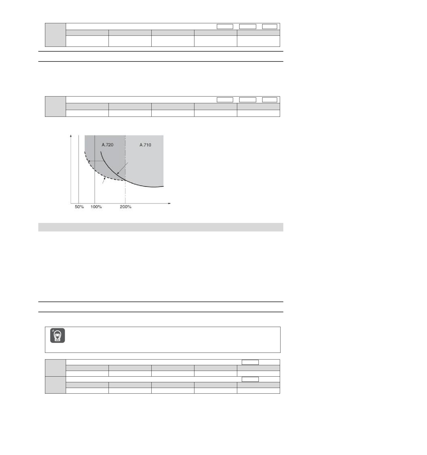
Overload (continuous maximum) alarm (A.720) can be detected in advance to prevent overload of the motor.
Overload detection time
Pn52C=100%
(factory set)
overload alarm
detection curve
Pn52C=50%
overload alarm
detection curve
Torque command [%]
(Note) The gray part of the above figure indicates the area where A.710 and A.720 occur.
5.12 Setting of Electronic Gear
"Command Unit" is the smallest unit of position data that moves the load. The command unit is to convert the
movement quantity into physical quantity units such as understandable distance (e.g. m and deg.), instead of
converting into pulses.
The electronic gear is a function of converting the movement amount specified according to the command unit
into the pulse number required for actual movement.
According to the electronic gear function, the workpiece movement amount per pulse of the input command
for servo drive is 1 command unit. That is, if servo-driven electronic gears are used, the pulses can be
converted into command units for reading.
(Note) When the upper device sets the electronic gear, the servo-driven electronic gear ratio is usually 1:1.
5.12.1 Setting of Electronic Gear Ratio
The electronic gear ratio is set by Pn20E and Pn210.
The setting range of the electronic gear ratio is as follows.
0.001≤ Electronic Gear Ratio (B/A) ≤64000
A.040 (parameter setting exception alarm) will occur when the setting range is exceeded.
Important
Electronic gear ratio (molecule)
Speed
Position
Torque
Pn20E
Setting range
Setting Unit
Factory setting
Effective time
Category
1~1073741824
1
1
Power restart
Setup
Electronic gear ratio (denominator)
Speed
Position
Torque
Pn210
Setting range
Setting Unit
Factory setting
Effective time
Category
1~1073741824
1
1
Power restart
Setup
Calculation Method for Setting Value of Electronic Gear Ratio
When the machine reduction ratio between the motor shaft and the load side is n/m (the load shaft rotates n
times when the motor rotates m times), the set value of the electronic gear ratio is obtained by the following
formula.
35
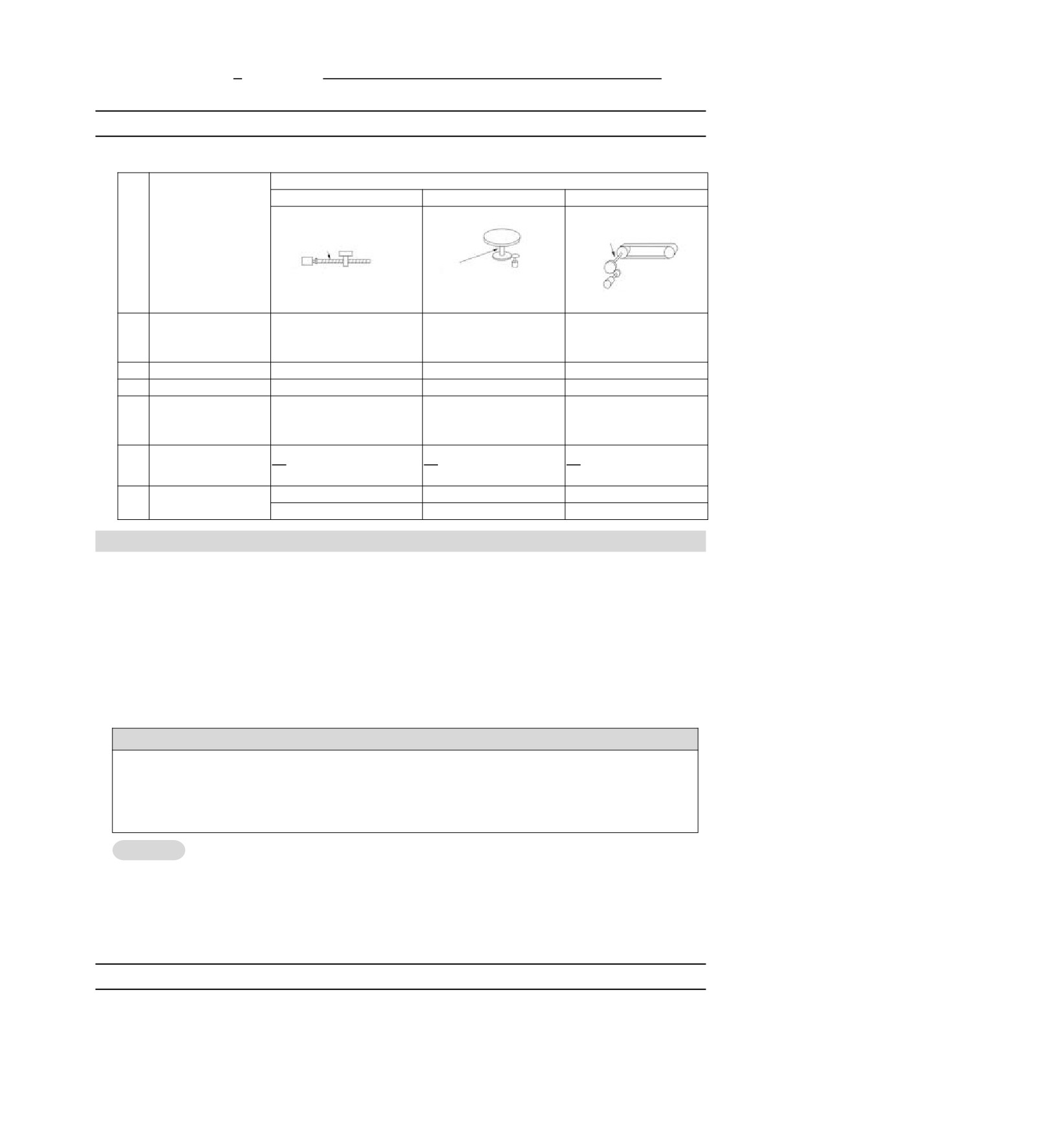
B
Encoder resolution
Electronic gear ratio
= Pn20E
=
×m
A
Pn210
The amount of movement (command unit) by which the load shaft rotates one circle
n
5.12.2 Setting Examples of Electronic Gear Ratio
Examples of settings are as follows.
Organizational structure
Ball screw
Frustum of a cone
Belt+pulley
Command unit: 0.01°
Command unit: 0.005mm
Command unit: 0.001mm
Reduction
Load shaft
Steps
Content
Load shaft
ratio 1/100
Reduction
Encoder
Pulley diameter
Load shaft Encoder 24 bits
ratio 1/50
24 bits
Lead of ball screw: 6mm
φ100mm
Encoder 24 bits
y Pulley diameter
:100mm
y Rotation angle of 1 turn:
y Lead of ball screw: 6mm
(pulley
circumference:
1
Mechanical specification
360
y Reduction ratio 1/1
314mm)
y Reduction ratio 1/100
y Reduction ratio 1/50
2
Encoder resolution
8388608(23 bits)
8388608(23 bits)
8388608(23 bits)
3
Command unit
0.001 mm (1 µm)
0.01
0.005 mm (5 µm)
The
amount
of
movement of the load
4
6 mm/0.001 mm = 6000
360°/0.01° = 36000
314 mm/0.005 mm = 62800
shaft by one revolution
(Command unit)
B
B
B
5
Electronic gear ratio
=8388608
×1
=8388608
×100
=8388608
×50
A
6000
1
A
36000
1
A
62800
1
Pn20E: 8388608
Pn20E: 838860800
Pn20E: 419430400
6
Parameter
Pn210: 6000
Pn210: 36000
Pn210: 62800
5.13 Setting of Absolute Value Encoder
When the system using absolute value encoder is put into use, the number of revolutions data should be
initialized. Therefore, when initialization needs to be performed such as the first power on, alarms related to
absolute value encoders will occur (A.810, A.820). By setting (initializing) the absolute value encoder, the
alarm related to the absolute value encoder will be cleared after the initialization of the rotation number data is
performed.
In the following situations, please set (initialize) the absolute value encoder.
• When the system is first put into use
• When A.810 (encoder backup alarm) occurs
• When A.820 (encoder and number check alarm) occurs
• When it is necessary to initialize the rotation number data of the absolute encoder
! Notes
After setting the absolute value encoder, the rotation number data is the value of-2 ~+2 coils. The reference
position of the mechanical system will change, so please locate the reference position of the upper device after
setting.
If the machine is directly operated without positioning the upper device, unexpected actions may occur, resulting
in personal injury or mechanical damage.
Supplementary
1. There is no rotation number data (usually zero) in the following situations, so it is not necessary to set
notes
(initialize) the absolute value encoder.There will be no alarm related to absolute value encoder (A.810,
A.820).
• When using a 1-turn absolute value encoder
• When the multi-turn absolute value encoder is used as one-turn absolute value encoder (Pn002 =
n.2)
2. When using a battery-free absolute value encoder, A.810 (encoder backup alarm) will occur when the
power is turned on for the first time. Perform absolute value after the encoder is set (initialized), A.810 will
not occur.
5.13.1 Precautions in Setting (Initializing)
"A.810 (Encoder Backup Alarm)" and "A.820 (Encoder and Number Verification Alarm)" cannot be released
by the servo-driven alarm reset input (/ALM-RST) signal. Therefore, it is important to set (initialize) the
absolute value encoder.
When an alarm (A.8) monitored by the encoder occurs, please remove the alarm by cutting off the power
supply.
36
5.13.2 Confirmation before execution
Before setting (initializing) the absolute value encoder, be sure to confirm the following.
The write inhibit setting for the parameter must not be set to "writeinhibited"
Must be in servo OFF state
5.13.3 Operable tool
The tools that can set (initialize) the absolute value encoder and their allocation to the setting (initialization) of
the absolute value encoder are as follows.
Operating tool
Distribution
Panel operator
Fn008
iWatch+ debugging
[Absolute value Encoder Reset]
software
5.14 Setting of Regenerative Resistance Capacity
Regenerative resistance refers to the resistance that consumes regenerative energy generated under the
conditions of servo motor deceleration, etc.
When connecting external regenerative resistor, Pn600
(regenerative resistor capacity) and Pn603
(regenerative resistor value) shall be set.
! Warning
y When connecting external regenerative resistors, be sure to set appropriate values for Pn600 and Pn603.
Otherwise, A.320 (regenerative overload alarm) will not be detected normally, which may lead to damage of
external regenerative resistor, personal injury and fire.
y When selecting an external regenerative resistor, be sure to confirm whether the capacity is appropriate.
Otherwise, injuries and fires may result.
Regenerative Resistance Capacity
Speed
Position
Torque
Setting range
Setting Unit
Factory setting
Effective time
Category
0 ~ Maximum
Pn600
applicable motor
Effective
10W
0
Setup
capacity for servo
immediately
drive
Regenerative resistor value
Speed
Position
Torque
Setting range
Setting Unit
Factory setting
Effective time
Category
Pn603
Effective
0~65535
10mΩ
0
Setup
immediately
The regenerative resistance capacity shall be set to a value matching the allowable capacity of the connected
external regenerative resistance. The set value varies depending on the cooling state of the external
regenerative resistor.
yIn the self-cooling mode (natural convection cooling), it is set to a value less than 20% of the regenerative
resistance capacity (W).
yIn forced air cooling mode, it is set to a value less than 50% of the regenerative resistance capacity (W).
Case
When the capacity of the self-cooling external regenerative resistor is 100 W, 100 W×20% =20W, so Pn600
(regenerative resistor capacity) should be set to "2" (setting unit: 10 W).
(Note) 1. If the set value is inappropriate, A.320 will be displayed.
2. Factory setting "0" is the set value when servo drive is used to drive the built-in regenerative resistor or the regenerative
resistor unit produced by our company.
yWhen the external regenerative resistor is used at the normal rated load rate, the temperature of the resistor
will reach 200 ℃
~ 300 ℃ , so please reduce the rated value before using. For the load characteristics of
resistors, please consult the manufacturer.
y To ensure safety, it is recommended to use an external regenerative resistor with a temperature control
Important
switch.
37
Chapter 6
Application function
6.1 Distribution of input and output signals
The I/O signal connector (CN1) has pre-assigned functions, but some terminals can be assigned other
functions or change polarity. Function allocation and polarity setting are performed through parameters.
The distribution of input and output signals will be described below.
6.1.1
Distribution of input signals
When the distribution of input signals is changed for use
When the polarity of each signal of the forward drive input (P-OT) and the reverse drive input (N-OT) is
changed to the factory setting, the overtravel prevention function will not operate in case of abnormality such
as signal line disconnection. When this setting has to be adopted, please be sure to make action confirmation
to ensure there is no safety problem.
When multiple signals are distributed on the same input loop, they will become exclusive OR logic, and all
Important
input signals will act. Therefore, unexpected actions may occur.
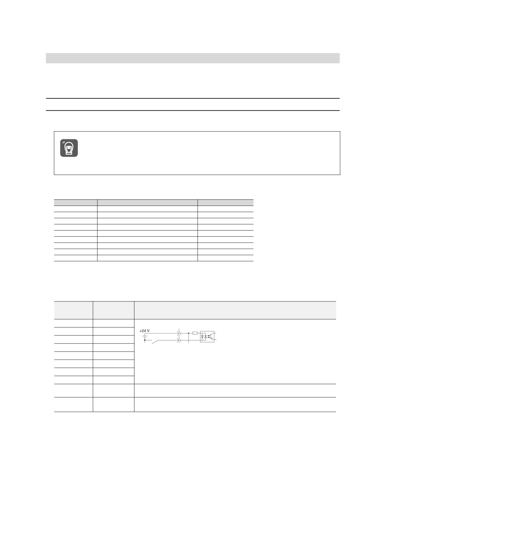
The relationship between the input signal assigned to the pin number of the input/output signal connector
(CN1) and the parameter setting is as follows.
Input signal
Name of input signal
Parameter
P-OT
Forward Drive Prohibit
Pn50A = n.X
N-OT
Reverse Drive Prohibit
Pn50B = n. X
/P-CL
Forward External Torque Limit
Pn50B = n.X
/N-CL
Reverse External Torque Limit
Pn50B = n.X
/DEC
Origin Return Deceleration Switch Input
Pn511 = n. X
/EXT1
External Latch Input 1
Pn511 = n.X
/EXT2
External Latch Input 2
Pn511 = n.X
/EXT3
External Latch Input 3
Pn511 = n.X
FSTP
Forcibly stop input
Pn516 = n. X
◆ Relationship between parameter setting value and assigned pin number and polarity
The relationship between the parameter setting value of the input signal and the pin number and polarity of the
input/output signal connector (CN1) is as follows.
The Setting
Needle
value of the
Description
number
Parameters
0
IN0
1
IN1
2
IN2
3
IN3
4
IN4
Reversal signal (signal with "/"at the beginning of the signal name: /P-CL signal, etc.)
5
IN5
takes effect via cONtact on.
6
IN6
Signals (P-OT signals, etc.) without "/"at the beginning of the signal name take effect
7
IN7
through contact OFF.
If it is not allocated to the needle, the input signal is often invalid.
8
-
When no signal is used, the set value is set to "8".
Not allocated to the needle, the input signal is always valid.
9
-
When no signal is used, the set value is set to "9".
Examples of Changes in Input Signal Distribution
An example of replacing the anti-rotation side drive input (P-OT) signal assigned to CN1-IN1 with the origin
reset deceleration switch input (/DEC) signal assigned to CN1-IN3 is as follows.
Pn50A = n.1
Pn511 = n. 3 before change
↓
↓
Pn50A = n.3
Pn511 = n. 1 after change
Confirmation of input signal
The status of the input signal can be confirmed by monitoring the input signal.
Input signal monitoring operation reference: 8.3.2 Monitoring of input and output
38
6.1.2
Distribution of output signals
The output signal can be distributed to the output port of the input/output signal connector (CN1). Allocation is
set through Pn50E, Pn50F, Pn510, Pn514.
When the distribution of output signals is changed for use
yNo detected signal is in "OFF" state. For example, during speed control, the positioning completion output
(/COIN) signal is "OFF".
yIf the polarity of the brake control output (/BK) signal is reversed and used with positive logic, the brake will
stop when the signal line is broken. When this setting has to be adopted, please be sure to make action
Important
confirmation to ensure there is no safety problem.
yWhen multiple signals are distributed on the same output loop, they will be output by XOR logic.
Examples of Changes in Output Signal Distribution
After the positioning completion output (/COIN) signal assigned to CN1-OUT3 is set to invalid, an example of
assignment of the servo ready output (/S-RDY) signal is as follows.
Pn50E = n.03
↓
Pn50E = n.30
Confirmation of Output Signal Status
The status of the output signal can be confirmed through output signal monitoring.
Output signal monitoring operation reference: 8.3.2 Monitoring of input and output
6.1.3
Servo Alarm Output (ALM) Signal
The servo alarm output (ALM) signal is the signal output when the servo drive detects a fault.
Please design an external circuit that turns OFF the power supply of the servo-driven main circuit through the
alarm output when a fault occurs.
Important
Signal
Type
Connector pin number
Signal status
Meaning
name
ON (closed)
Servo drive normal state
Output
ALM
Distribution required
OFF (OFF)
Servo drive alarm status
6.1.4
Warning output (/WARN) signal
The servo drive is provided with alarms and warnings.
The alarm indicates that there is an abnormality in the servo drive and the operation needs to be stopped
immediately.
The warning is an announcement before the alarm occurs and does not need to stop running.
The warning output (/WARN) signal refers to the warning before the alarm occurs
Signal
Type
Connector pin number
Signal status
Meaning
name
ON (closed)
Exception Warning Status (Warning Status)
Output
/WARN
Distribution required
OFF (OFF)
Normal status
(Note) /WARN signal needs to be distributed. Can be set to Pn50F = n. X (distribution of warning output (/WARN) signal) and
distributed to terminals.
6.1.5
Rotation detection output (/TGON) signal
The rotation detection output (/TGON) signal is a signal indicating that the servo motor is running.
Servo motor according to Pn502 (rotation detection value).
Signal
Type
Connector pin number
Signal status
Meaning
name
The servo motor is rotating at a speed higher than the Pn502
Output
/TGON
Distribution required
ON (closed)
set point.
Set the detection value of the speed of the output /TGON signal.
39
Rotation detection value
Speed
Position
Torque
Setting range
Setting Unit
Factory setting
Effective time
Category
Pn502
Effective
0~10000
1 min-1
20
Setup
immediately
6.1.6
Ready output (/S-RDY) signal
The servo ready output (/S-RDY) signal turns ON in a state where the servo drive can receive a servo ON
(SV_ON) command.
The /S-RDY signal is output (turned ON) under the following conditions.
y Main circuit power supply ON.
y Non-hardware base blocking state.
y No alarm has occurred.
y When the absolute value encoder is used, the sensor ON (SENS_ON) command is input.
y Magnetic Pole Detection Completed (Servo Motor Without Magnetic Pole Sensor)
y When using the absolute value encoder, in addition to the above state, the servo ready signal can be output
only under the condition that "the position data of the absolute value encoder has been output to the upper
device when the sensor ON (SENS_ON) command is input".
* This condition is excluded when the servo ON (SV_ON) command is input for the first time after the control
power is turned on. In this case, when the SV_ON command is input, the magnetic pole detection will start
synchronously with the first SV_ON command, and after the magnetic pole detection is completed, the
/S-RDY signal will be ON.
Signal
Type
Connector pin number
Signal status
Meaning
name
State in which servo ON (SV_ON) command can
ON (closed)
be received
Output
/S-RDY
Distribution required
The state in which the servo ON
(SV_ON)
OFF(OFF)
command cannot be received.
(Note) /S-RDY signal can be distributed. It can be set to Pn50E = n. X (distribution of servo ready output (/S-RDY) signal) and
distributed to terminals.
6.1.7
Speed consistent output (/V-CMP) signal
The speed coincidence output (/V-CMP) signal is a signal output when the rotational speed of the servo motor
coincides with the commanded speed. Used for interlocking with the upper device and other occasions. This
output signal can only be used for speed control.
/V-CMP signal is shown below.
Signal
Type
Connector pin number
Signal status
Meaning
name
ON (closed)
Velocity consistent state
Output
/V-CMP
Distribution required
OFF (OFF)
Speed inconsistency
(Note) /V-CMP signal needs to be distributed. It can be set to Pn50E= n.X (distribution of speed consistent output
(/V-CMP) signal) and distributed to terminals.
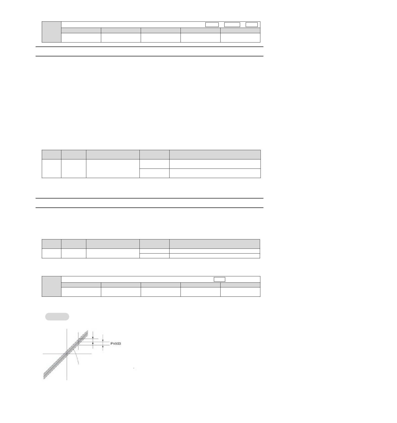
The speed detection range of the /V-CMP signal is set by Pn503.
Detection range of speed consistent signals
Speed
Setting range
Setting Unit
Factory setting
Effective time
Category
Pn503
Effective
0~100
1 min-1
10
Setup
immediately
When the difference between the motor speed and the commanded speed is lower than the set value, the
signal is output.
Pn503=100, output signal when the command speed is 2000min-1 and the motor speed is 1900 ~ 2100 min-1.
Case
Speed command
The "/V-CMP signal" is output when the motor
speed changes to the speed within the range
enclosed by the dotted line.
40
6.1.8
Positioning Completion (/COIN) Signal
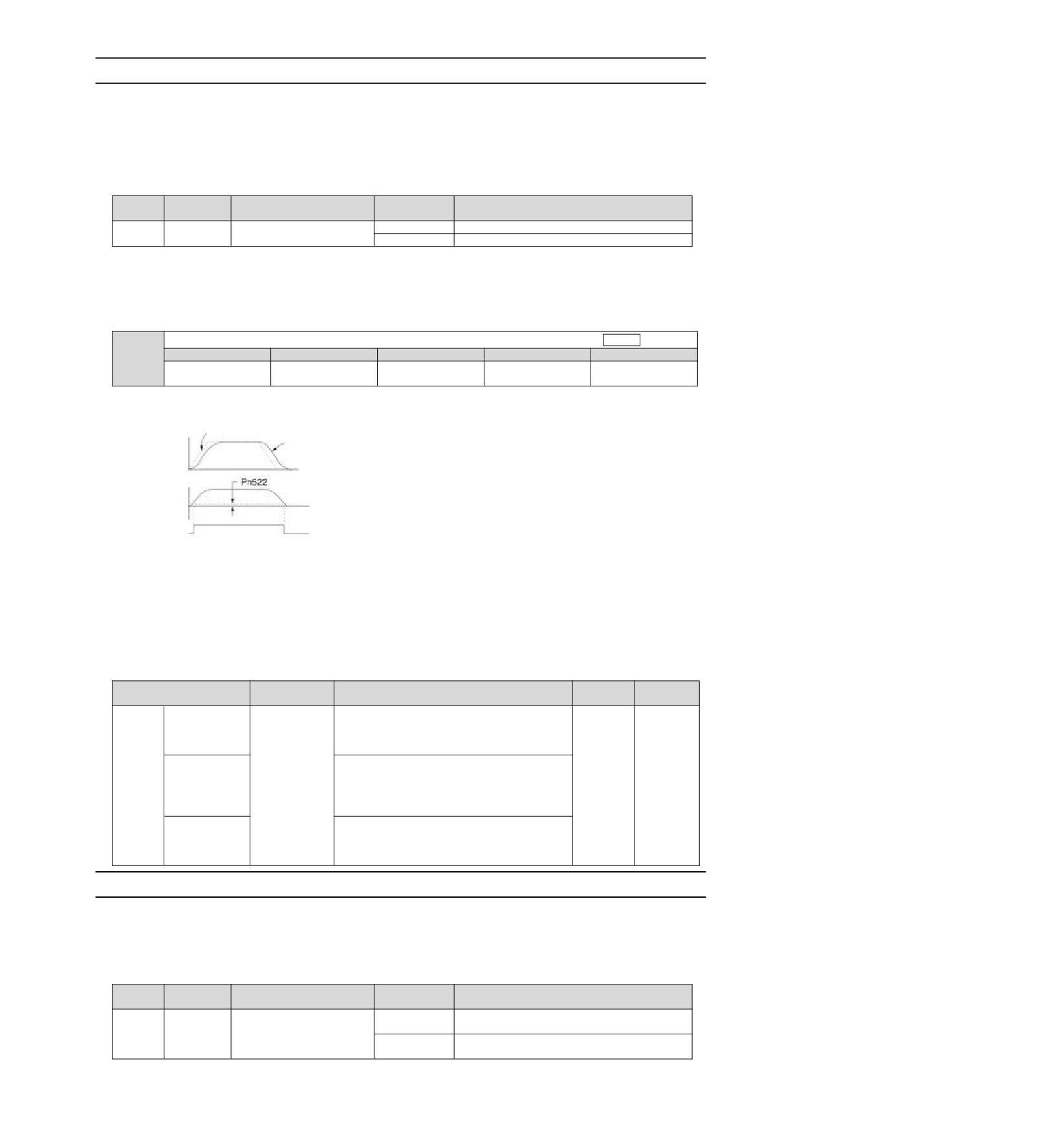
When the positioning completion output (/COIN) signal is position control, it indicates the servo motor
positioning completion signal.
When the difference between the command position from the upper device and the current position of the
servo motor (position deviation: value of deviation counter) is less than the set value of the positioning
completion amplitude (Pn522), a /COIN signal will be output.
For the upper device to confirm that the positioning has been completed.
Signal
Type
Connector pin number
Signal status
Meaning
name
ON (closed)
Positioning is completed
Output
/COIN
Distribution required
OFF (OFF)
Positioning is not completed
(Note) /COIN signal needs to be distributed. It can be set to Pn50E = n.X (distribution of positioning complete output (/coil)
signal) and distributed to terminals.
Setting of positioning completion amplitude
The positioning completion amplitude (Pn522) outputs a signal when the difference between the command
position and the current position (position deviation: value of deviation counter) is smaller than the set value.
Positioning completion amplitude
Position
Setting range
Setting Unit
Factory setting
Effective time
Category
Pn522
Effective
0~1073741824
1 Command unit
10
Setup
immediately
y This parameter setting has no influence on the final positioning accuracy.
Command
Speed
Motor speed
Time
Location deviation
Time
/COIN signal
(ON (Closed) Valid)
Time
(Note) If the set value is too large and the deviation during low-speed operation is small, a constant /COIN signal may be output.
When outputting the signal, please lower the set value until the signal is no longer output.
Setting of Output Time for Positioning Complete Output (/COIN) Signal
Command input condition can be added to the output condition of the /COIN signal to change the output time.
When used in a state where the positioning completion amplitude is small and the position deviation is
generally small, it can be set to Pn207 = n.X (positioning completion output (/COIN) signal output time)
to change the output time of the /COIN signal.
Effective
Parameter
Name
Content
Category
time
When the absolute value of the position
n.0
deviation is smaller than the positioning
[Factory
completion amplitude
(Pn522), the
/COIN
setting]
signal is output.
Positioning
When the absolute value of the position
completion
deviation is less than the positioning
output
Power
Pn207
n.1
completion amplitude (Pn522) and the filtered
Setup
(/COIN)
restart
command of the position command is 0, the
Signal Output
/COIN signal is output.
Time
When the absolute value of the position
deviation is smaller than the positioning
n.2
completion amplitude (Pn522) and the position
command input is 0, the /COIN signal is output.
6.1.9
Position nearby output (/NEAR) signal
The near positioning output (/NEAR) signal is a signal notifying the near positioning completion position.
In position control, the upper device receives the positioning approach signal before confirming the
positioning completion signal, thus preparing for the action sequence after positioning is completed. In
this way, the time required for action when positioning is completed can be shortened.
This signal is usually used in pairs with the positioning completion output (/COIN) signal.
Signal
Type
Connector pin number
Signal status
Meaning
name
Output when reaching the positioning completion
ON (closed)
approach point
Output
/NEAR
Distribution required
The positioning completion approach point has
OFF (OFF)
not been reached.
41

(Note) /NEAR signal needs to be distributed. It can be set to Pn510=n.X (distribution of positioning complete output (/NEAR)
signal) and distributed to terminals.
Position the setting of NEAR output amplitude.
In Pn524 (NEAR Signal Amplitude), the condition for outputting the positioning proximity output (/NEAR) signal
(positioning proximity amplitude) is set. The
/NEAR signal is output when the difference between the
command position and the current position (position deviation = deviation counter value) is less than the set
value of Pn524.
NEAR signal amplitude
Speed
Position
Torque
Setting range
Setting Unit
Factory setting
Effective time
Category
Pn524
Effective
0~1073741824
1 Command unit
1073741824
Setup
immediately
Speed
Command
Motor speed
Time
Location deviation
Time
/NEAR signal
(ON (Closed) Valid)
Time
/COIN signal
(ON (Closed) Valid)
Time
(Note) Generally, please set it to a value greater than Pn522 (positioning completion amplitude).
6.1.10 Speed limit function during torque control
The function of limiting the speed of a servo motor in order to protect machinery.
During torque control, the servo motor will be controlled in the form of output command torque, but the motor
speed will not be controlled. Therefore, if a command torque greater than the mechanical side torque is input,
the motor speed will be greatly increased. In this case, the speed must be limited by this function.
(Note) According to the load condition of the motor, there will be a certain gap between the limited speed of the motor and the set
value.
Unlimited speed
Limited speed
Overspeed may cause
Speed
mechanical damage!
Speed
Maximum speed
Limit the speed, you
can rest assured!
Limited speed
Time
Time
Speed limit detection output (/VLT) signal
The output signal of the motor speed after being limited is as follows.
Signal
Type
Connector pin number
Signal status
Meaning
name
ON (closed)
Motor speed limitated
Output
/VLT
Distribution required
OFF (OFF)
Motor speed is not limited
(Note) /VLT signal needs to be distributed. It can be set to Pn50F=n.X (distribution of speed limitation output (/VLT) signal) and
distributed to terminals.
Selection of Speed Limit Value
The speed limit value is set via Pn002 = n. X (torque limit option). When set to Pn.002=n. 1
(external speed limit function), the smaller of the external speed limit value and the internal speed limit value is
valid.
Effective
Parameter
Meaning
Category
time
n.0
Appointment Parameters (Do Not Set)
n. 1
The speed limit value of torque control (VLIM command) is
Power
Pn002
Setup
[Factory
used as the speed limit value.
restart
setting]
(External Speed Limit Function)
◆ Internal speed limit function
The limit value of the motor speed is set by Pn407 (speed limit during torque control).
42
In addition, through Pn408 = n X (speed limit selection), the upper speed limit value used for the speed
limit value can be selected from "motor maximum speed" and "overspeed alarm detection speed". When
limited by a speed equal to the maximum speed of the motor, select "Overspeed Alarm Detection Speed".
Effective
Parameter
Meaning
Category
time
n.0
The speed limit value uses "motor maximum speed", the smaller
[Factory setting]
of Pn407 settings.
Power
Pn408
Setup
The speed limit value uses "speed detected by overspeed
restart
n.1
alarm", the smaller of the Pn407 set values.
(Note) When using a rotary servo motor, Pn407 (speed limit during torque control) is set.
Speed limit during torque control
Spee
Torque
Setting range
Setting Unit
Factory setting
Effective time
Category
Pn407
Effective
0~10000
1 min-1
10000
Setup
immediately
(Note) Even if the set value exceeds the maximum speed of the servo motor used, the actual speed will be limited to the maximum
speed of the servo motor used or the overspeed alarm detection speed.
◆External Speed Limit Function
When selecting the external speed limit function through Pn002=n.X, the motor speed is limited by the
speed limit value (VLIM).
6.2
Operation for Momentary Power Interruptions
By setting, even if the power supply of the servo drive main circuit is turned OFF instantaneously, the motor
can cONtinue to be powered on (servo on) according to the time set by Pn509 (instantaneous power failure
holding time).
Transient outage holding time
Speed
Position
Torque
Setting range
Setting Unit
Factory setting
Effective time
Category
Pn509
Effective
20~50000
1 ms
20
Setup
immediately
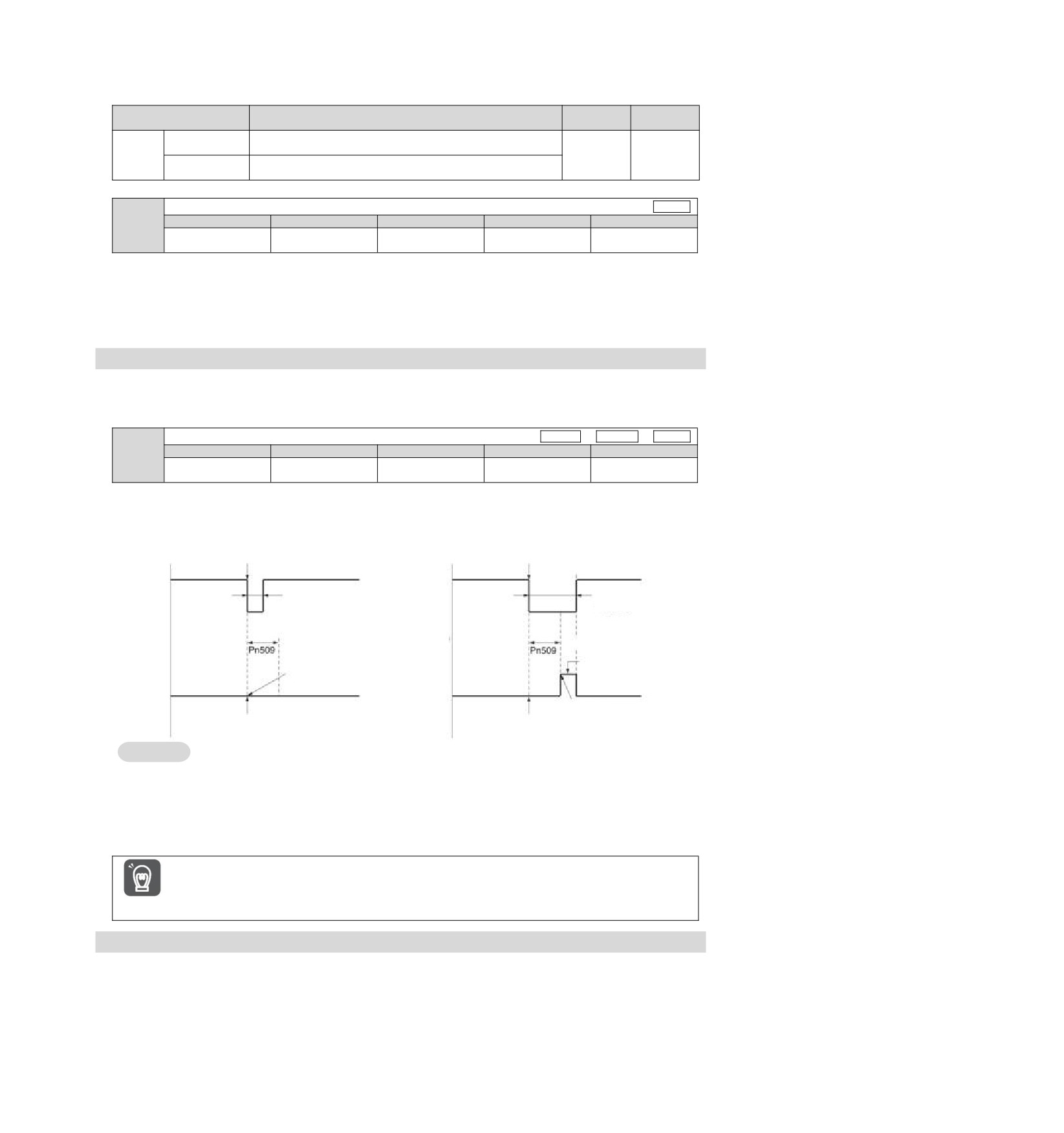
When the instantaneous power failure time is less than the set value of Pn509, the motor will continue to be
powered on, and when it is greater than the set value, the motor will no longer be powered on. When the main
circuit power supply is restored, the motor will be powered back on.
Instantaneous power failure occurs when the set
Instantaneous power failure occurs when the set
value of Pn509 is ≥ instantaneous stop time
value of Pn509 is < instantaneous stop time
Main circuit
Instant stop time
Main circuit
Instant stop time >
power supply
≤Pn509
power supply
Pn509
Pn509 set
Pn509 set
point
point
The motor is not energized
Continue to energize
The motor is
the motor
The motor is
Electrical
energized
Electrical
energized
machine
machine
energized state
energized state
Power cut off
Instantaneous power failure occurred
Instantaneous power failure occurred
Supplementary
1. When the instantaneous power failure time is greater than the set value of Pn509, the servo
notes
ready output (/S-RDY) signal is OFF and the servo is OFF.
2. The control power supply and the main circuit power supply can cope with power outages of
more than 5000ms when using non-power-off equipment.
3. The holding time of servo drive control power supply is about 100ms. The control power
supply cannot be controlled during an instantaneous power failure. When the same
processing as the normal power supply OFF operation is performed, the Pn509 setting will be
invalid.
The holding time of the main loop power supply varies depending on the output of the servo
drive. This setting is invalid when the load of servo motor is large and "A.410 (under voltage
alarm)" occurs during instantaneous power failure.
Important
6.3 SEMI F47 Specification Support Function
SEMI F47 support function refers to the function of detecting A.971 (under voltage) warning and limiting the
output current when the DC voltage of the main circuit inside the servo drive falls below the specified value
due to instantaneous power failure or temporary low power supply voltage of the main circuit.
This function supports SEMI F47 specifications required by semiconductor manufacturing devices.
This function is used in combination with the setting function of the instantaneous power failure holding time
(Pn509), and can continue to operate even when the power supply voltage is reduced, so that no shutdown is
caused due to alarm, and no recovery operation is required.
43
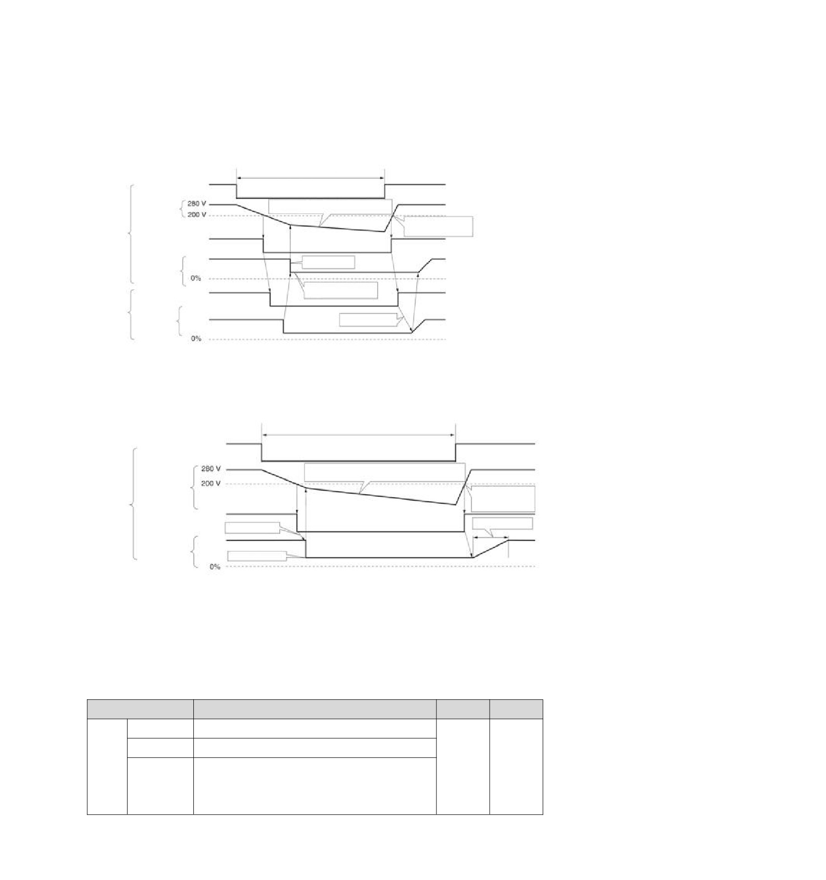
Execution sequence
This function can be executed by a command issued by an upper device or a servo drive unit. Whether it is
executed by the upper device or servo drive unit is selected by Pn008=n. X (function selection under
voltage).
◆ When executed by the upper device (Pn008=n.1)
Upper device limits the torque after receiving an under voltage (A.971) warning.
After receiving the undervoltage warning release signal, the torque limit is released.
Main circuit power cut-off time
Main circuit input
power supply
Main circuit
By limiting the output torque, the bus voltage
bus voltage
of the main circuit is gradually reduced.
The bus voltage of the main
circuit rises after the main
circuit power supply is
Servo unit
Undervoltage (A.971)
restored
Warning
Torque limit start
Torque limit
Limit torque after receiving
Undervoltage warning
undervoltage warning
status
Upper device
Torque limit
Release torque limit
command
◆ When torque limitation is performed by servo drive unit (Pn008=n.2)
According to the under-voltage warning, a torque limit is applied inside the servo drive.
After receiving the undervoltage warning release signal, the torque limit value is controlled inside the servo
drive according to the set time.
Main circuit power cut-off time
Main circuit input
power supply
By limiting the output torque, the bus voltage of the
main circuit is gradually reduced.
Main circuit bus
The bus voltage of the
voltage
main circuit rises after
the main circuit power
Servo unit
supply is restored
Undervoltage (A.971)
Warning
Pn425 set point
Torque limit start
Torque limit
Pn424 set point
Setting of Undervoltage (A.971) Warning
Set whether A.971 (undervoltage) warning is detected.
Effective
Parameter
Meaning
Category
time
n.0
Under voltage warning is not detected.
[Factory setting]
The undervoltage warning is detected, and the torque limit is
n. 1
executed by the upper device.
The undervoltage warning is detected, and torque limitation is
Power
Pn008
Setup
performed by Pn424 (torque limitation when the main circuit
restart
voltage is reduced) and Pn425 (torque limitation is performed
n. 2
according to the torque limitation release time when the main
circuit voltage is reduced).
(executed by servo drive unit)
◆ Relevant parameters
44
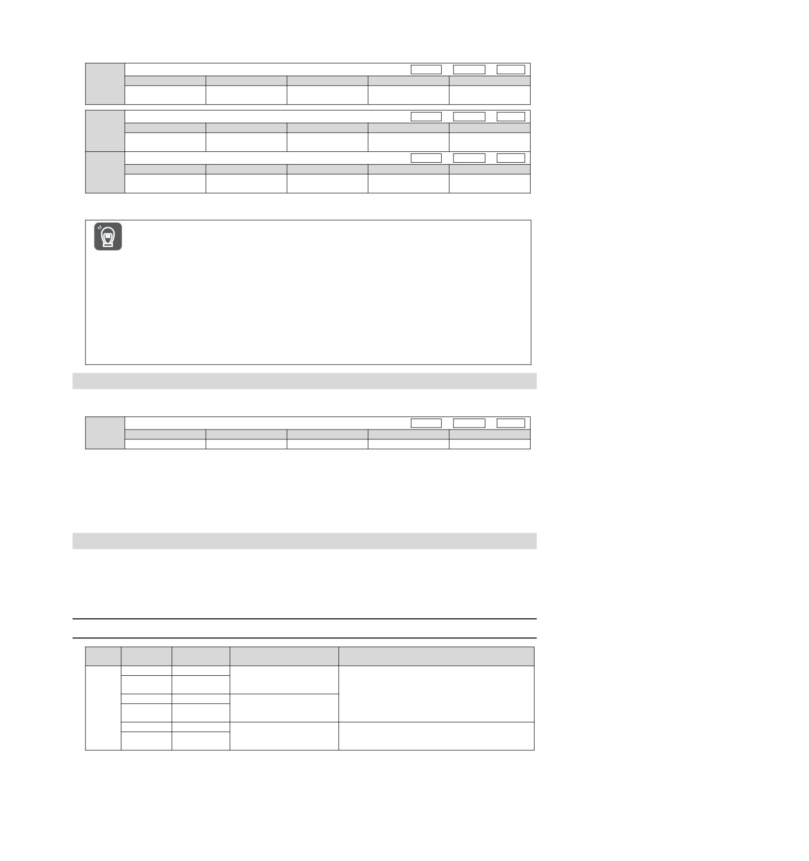
Parameters related to SEMI F47 specification support functions are as follows.
Torque limitation when main loop voltage drops
Speed
Position
Torque
Setting range
Setting Unit
Factory setting
Effective time
Category
Pn424
Effective
10~100
1% *
50
Setup
immediately
Torque limit release time when main loop voltage drops.
Speed
Position
Torque
Setting range
Setting Unit
Factory setting
Effective time
Category
Pn425
Effective
10~1000
1 ms
100
Setup
immediately
Transient outage holding time
Speed
Position
Torque
Setting range
Setting Unit
Factory setting
Effective time
Category
Pn509
Effective
20~50000
1 ms
20
Setup
immediately
* Percentage relative to rated torque of motor.
(Note) When using functions meeting SEMI F47 specifications, please set it to 1000 ms
y This function is applicable to the instantaneous power failure of voltage and time within the scope specified
in SEMI F47 specification. For the instantaneous power failure of voltage and time beyond this scope,
standby UPS is required.
Important
y When the power supply of the main circuit is restored, please use the torque limit set by the upper device
or servo drive to prevent the output torque from being greater than the commanded acceleration torque.
y When used for vertical shafts, do not limit the torque below the holding torque.
y This function is to limit the torque within the servo drive capability in the power failure state, and is not
applicable to all load conditions or operating conditions. Please be sure to set the parameters while
confirming the action through the actual device.
y After setting the holding time of instantaneous power failure, the time from power cut-off to power cut-off of
the motor will become longer. When the motor is powered off immediately, please use the servo
OFF(SV_OFF)
6.4 Setting of Maximum Speed of Motor
The maximum speed of the servo motor is set by the following parameters.
Maximum speed of motor
Speed
Position
Torque
Pn316
Setting range
Setting Unit
Factory setting
Effective time
Category
0~65535
1 min-1
10000
Power restart
Setup
By reducing the maximum speed of the servo motor, the servo drive can realize the following processing.
y A.510 (overspeed alarm) occurs when the motor speed exceeds the set value.
Valid when changing parameter settings in the following situations.
y In order to protect the machinery, it is necessary to stop the operation of the machinery through an alarm
when the set speed is exceeded.
y When the speed needs to be limited so that the motor drives the load above the allowable moment of inertia
6.5 Encoder frequency division pulse output
The encoder frequency division pulse output is a signal that is output to the outside in the form of 2-phase
pulses (phase A and phase B) with a phase difference of 90 degrees after the servo drive internally processes
the signal sent by the encoder. It is used as position feedback in the upper device.
The form of the signal and the output phase is as follows.
6.5.1
Signal output by encoder frequency division pulse
Signal
Connector
Type
Name
Remarks
name
pin number
PAO+
CN1-19
Encoder
frequency
When the encoder frequency-divided pulse is
division
pulse
output
output, the number of pulses set by the encoder
PAO-
CN1-20
phase A
frequency-divided pulse number
(Pn212) is the
PBO+
CN1-21
Encoder
frequency
number of pulses that the motor rotates once. The
Output
division
pulse
output
phase difference between phase A and phase B is
PBO-
CN1-22
phase B
90 degrees.
PCO+
CN1-23
Encoder
frequency
division
pulse
output
The motor rotates once to output one pulse.
PCO-
CN1-24
phase C
45
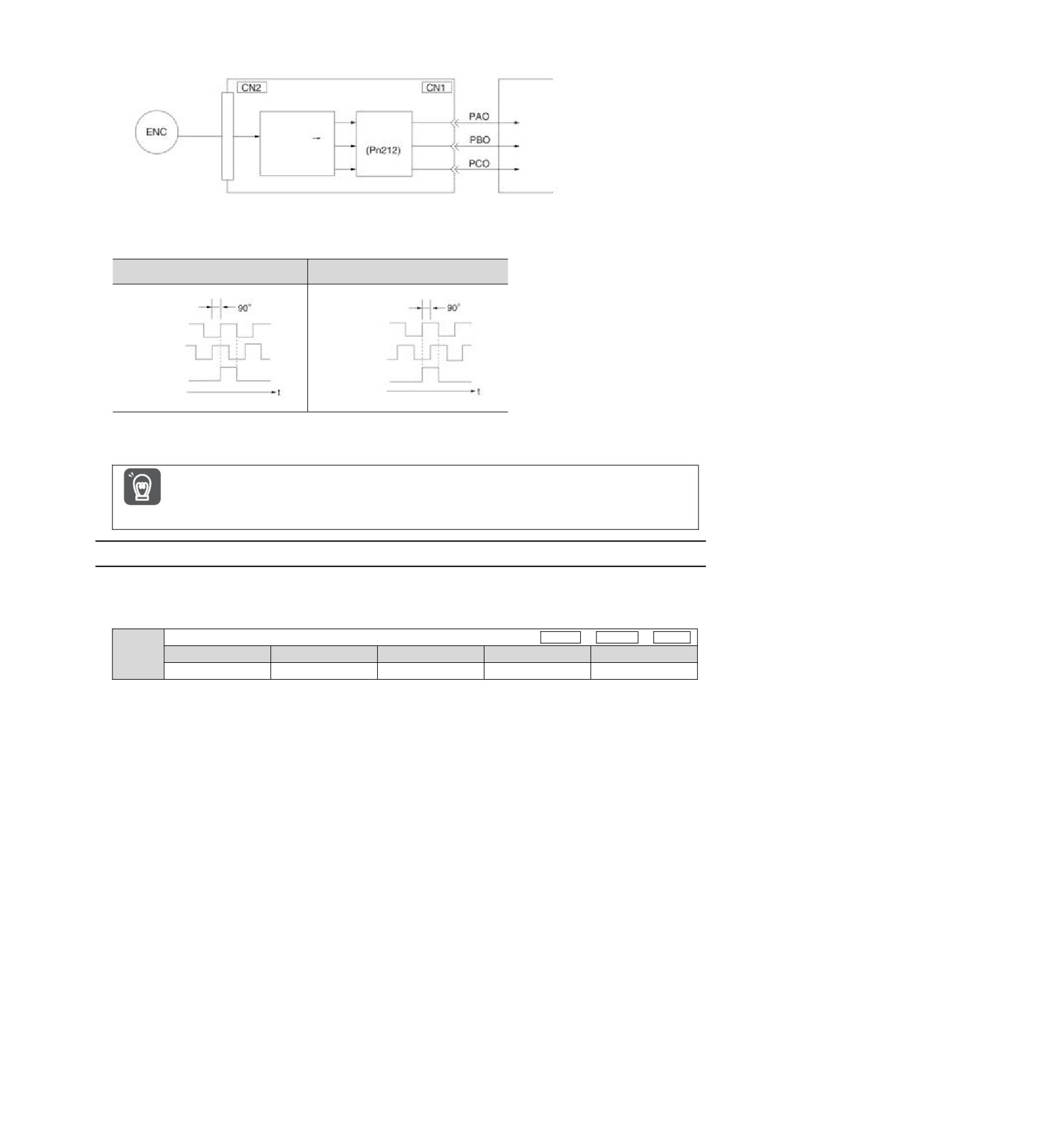
Servo unit
Upper device
Serial
data
Frequency
Serial Data
division loop
Pulse Conversion
Output phase morphology
When rotating forward (forward
When reversing (negative direction)
direction) (phase b 90 leading)
(phase a 90 leading)
A Phase
A Phase
B Phase
B Phase
C Phase
C Phase
(Note) The pulse amplitude of the origin within the encoder 1 coil varies depending on the number of encoder divided pulses (Pn212)
and the encoder output resolution (Pn281). Same amplitude as phase A.
In reverse (negative direction) mode (Pn000 = n.1), the output phase shape is the same as the above figure.
When performing mechanical origin reset operation through servo-driven C-phase pulse output, please
make the servo motor run for more than 2 turns before operating. If this operation cannot be performed,
please set the speed of the servo motor below 600 min-1, and then perform origin reset. When the speed is
Important
above 600 min-1, the C-phase pulse may not be correctly output.
6.5.2
Setting of Encoder frequency division pulse output
The following describes the setting method of encoder frequency division pulse output.
Encoder frequency division pulse count (Pn212) Settings
Encoder frequency division pulse count
Speed
Position
Torque
Pn212
Setting range
Setting Unit
Factory setting
Effective time
Category
16~1073741824
1 pitch /Rev
2500
Power restart
Setup
The number of pulses per revolution sent by the encoder is processed in the servo drive, and then is output
after frequency division according to the set value of Pn212.
Please set the output number of encoder frequency division pulses according to the system specifications of
mechanical and upper devices.
The setting of the frequency division pulse number of the encoder will be limited by the encoder resolution.
(Note) 1. The setting range of the encoder frequency division pulse number (Pn212) varies depending on the encoder resolution of
the servo motor used. If the setting conditions in the above table cannot be met, A.041 (abnormal frequency division pulse
output setting) will occur.
Example of correct setting: when Pn212 is 2500 [P/Rev]
Example of wrong setting: when Pn212 = 2501 [P/Rev] → setting scale is different from the above table, so output A.041
2. The upper limit of pulse frequency is about 1.6 Mpps. If the set value of encoder frequency division pulse number is too
high, the speed of servo motor will be limited. If the upper limit of the motor speed in the above table is exceeded, A.511
(frequency division pulse output overspeed) will occur.
Output Example: When Pn212 = 16 (16 pulses per turn), the output examples of encoder frequency-divided
pulse output phase A (PAO) signal and encoder frequency-divided pulse output phase B (PBO) signal are as
follows.
46
Setting value: 16
PAO signal
PBO signal
1 circle
47
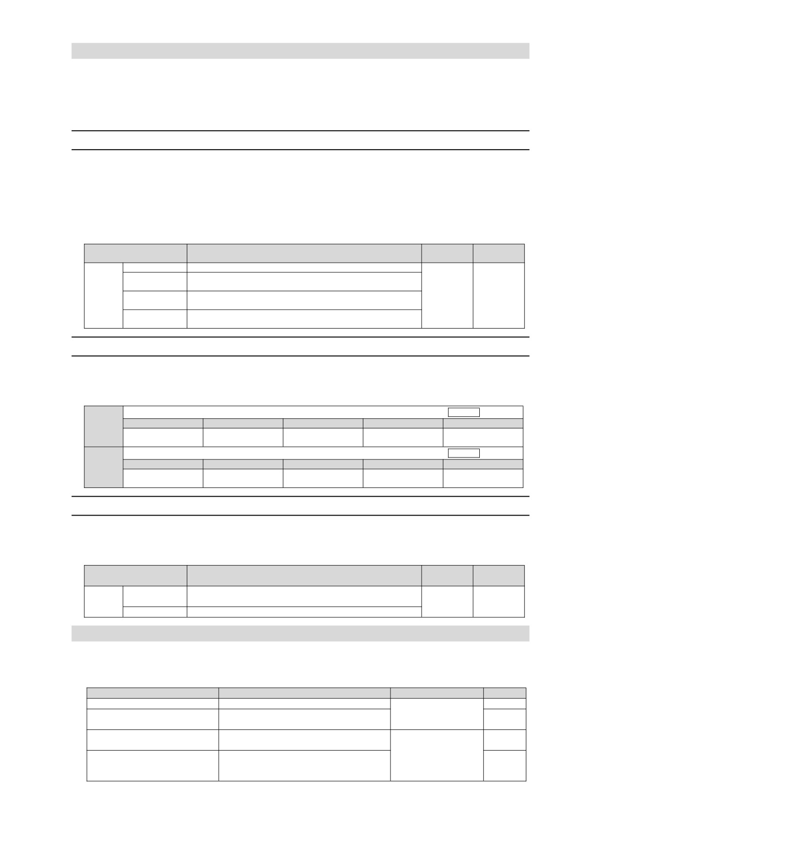
6.6 Soft limit function
The so-called soft limit refers to the function of forcibly stopping when the movable part of the machine
exceeds the soft limit when no overtravel signal (P-OT, N-OT) is used.
When using soft time limit, the following settings are required.
ySet the soft limit function to active
ySet soft limit
6.6.1
The valid/invalid choice of soft limit function
The valid/invalid soft limit function is set by Pn801 = n.X (soft limit function).
The soft limit function is effective in the following situations (determining the state of the origin of the
mechanical coordinate system). In other cases, the soft limit function does not operate even if it exceeds the
soft limit range.
y After completing the ZRET command
y After executing REFE = 1 command with POS_SET command
y When using the absolute value encoder, after completing the sensor ON (SENS_ON) command
Effective
Parameter
Meaning
Category
time
n.0
Set both soft limits to be valid
Set the forward turning side (forward direction) soft limit to be
n. 1
invalid
Effective
Pn801
The soft limit on the reverse (negative direction) side is
Setup
n. 2
immediately
invalidated.
n. 3
Set both soft limits to be invalid
[Factory setting]
6.6.2
Setting of soft limit value
Set the soft limits on the forward and reverse sides.
The area needs to be set according to the direction, so be sure to set it to "reverse side soft limit value <
forward side soft limit value".
Forward side soft limit
Speed
Position
Torque
Setting range
Setting Unit
Factory setting
Effective time
Category
Pn804
-1073741823~
Effective
1 Command unit
1073741823
Setup
1073741823
immediately
Reverse side soft limit
Speed
Position
Torque
Setting range
Setting Unit
Factory setting
Effective time
Category
Pn806
-1073741823~
Effective
1 Command unit
-1073741823
Setup
1073741824
immediately
6.6.3
Carry out soft limit check according to commands
Set whether soft limit check is carried out when commands such as POSING or INTERPOLATE are sent to the
target location. If the target position exceeds the soft limit, deceleration stop is executed at the position where
the soft limit is set.
Effective
Parameter
Meaning
Category
time
n.0
No command soft limit check
Effective
Pn801
[Factory setting]
Setup
immediately
n.1
There is command soft limit check
6.7 Selection of torque limit
Torque limitation is the function of limiting the output torque of servo motor.
There are four kinds of torque limitation modes, and the summary of each limitation mode is as follows.
Mode of restriction
Summary
Control mode
Remarks
Internal torque limit
Torque is normally limited by parameters.
Speed control
Torque is limited by an input signal from an
Position control
Exterior torque limit
upper device.
Torque control
Torque Limits for Command-Based
Through the commanded TLIM data, torque
TLIM Data *
limitation is arbitrarily performed.
Speed control
Torque limit of P_CL, N_CL based
Torque is limited by P_CL, N_CL of the servo
Position control
on servo command output signal
command output signal (SVCMD_IO).
(SVCMD_IO) *
(Note) Even if the set value exceeds the maximum torque of the servo motor used, the actual torque will be limited within the
maximum torque of the servo motor.
48
6.7.1
Internal torque limit
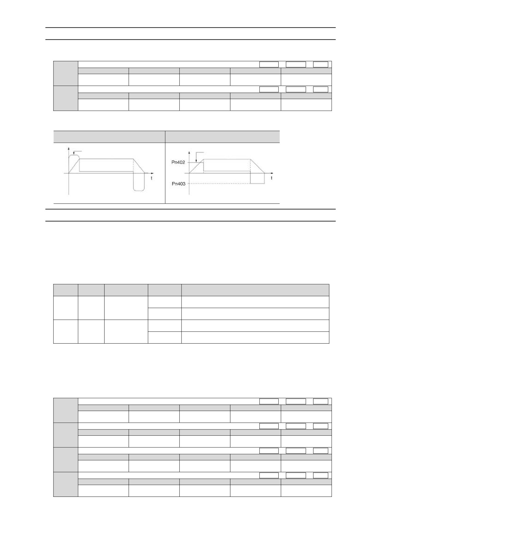
The internal torque limit limits the maximum output torque at a constant time by the torque limit values set by
the forward torque limit (Pn402) and the reverse torque limit (Pn403).
Forward rotation torque limit
Speed
Position
Torque
Setting range
Setting Unit
Factory setting
Effective time
Category
Pn402
Effective
0~800
1% *
800
Setup
immediately
Reversal torque limit
Speed
Position
Torque
Setting range
Setting Unit
Factory setting
Effective time
Category
Pn403
Effective
0~800
1% *
800
Setup
immediately
* Percentage relative to rated torque of motor.
(Note) If the set values of Pn402 and Pn403 are too small, insufficient torque may occur during acceleration and deceleration of the
servo motor.
No internal torque limit (maximum torque
There is internal torque limit
output)
Maximum torque
Limited torque
Speed
Speed
6.7.2
Exterior torque limit
When the machine needs torque limitation under certain operating conditions, the upper device sends an ON
or OFF signal to implement torque limitation.
It can be used for pushing and stopping action or holding the workpiece of the robot stably.
Command signal for external torque limitation
The command signals for external torque limitation include a forward rotation side external torque limitation
input (/P-CL) signal and a reverse rotation side external torque limitation input (/N-CL) signal. The command
signal for forward rotation side torque limitation is /P-CL signal, and the command signal for reverse rotation
side torque limitation is /N-CL signal.
Signal
Connector pin
Signal
Type
Meaning
name
number
status
The external torque ON the forward rotation side is limited to ON.
ON (closed)
Distribution
Limit value: the smaller of the set values of Pn402 and Pn404
Input
/P-CL
required
The external torque on the forward rotation side is limited to OFF.
OFF (OFF)
Limit value: Pn402
The external torque ON the reversal side is limited to ON.
ON (closed)
Distribution
Limit value: the smaller of the set values of Pn403 and Pn404
Input
/N-CL
required
The external torque on the reversal side is limited to OFF.
OFF (OFF)
Limit value: Pn403
(Note) /P- CL signal,/N- CL signal needs to be distributed. The following parameters can be used to assign to terminals.
• Pn50B = n.X (distribution of external torque limit input (/P-CL) signal on forward rotation side)
• Pn50B = n.X (distribution of reverse side external torque limit input (/N-CL) signal)
Setting of torque limit
The parameters related to the set torque limit value are as follows.
If the set values of Pn402 (forward rotation torque limit), Pn403 (reverse rotation torque limit), Pn404 (forward
rotation side external torque limit), and Pn405 (reverse rotation side external torque limit) are too small,
insufficient torque may occur during acceleration and deceleration of the servo motor.
Forward rotation torque limit
Speed
Position
Torque
Setting range
Setting Unit
Factory setting
Effective time
Category
Pn402
Effective
0~800
1% *
800
Setup
immediately
Reversal torque limit
Speed
Position
Torque
Setting range
Setting Unit
Factory setting
Effective time
Category
Pn403
Effective
0~800
1% *
800
Setup
immediately
Forward rotation torque limit
Speed
Position
Torque
Setting range
Setting Unit
Factory setting
Effective time
Category
Pn404
Effective
0~800
1% *
100
Setup
immediately
Reversal torque limit
Speed
Position
Torque
Setting range
Setting Unit
Factory setting
Effective time
Category
Pn405
Effective
0~800
1% *
100
Setup
immediately
* Percentage relative to rated torque of motor.
49
Output torque variation at external torque limit
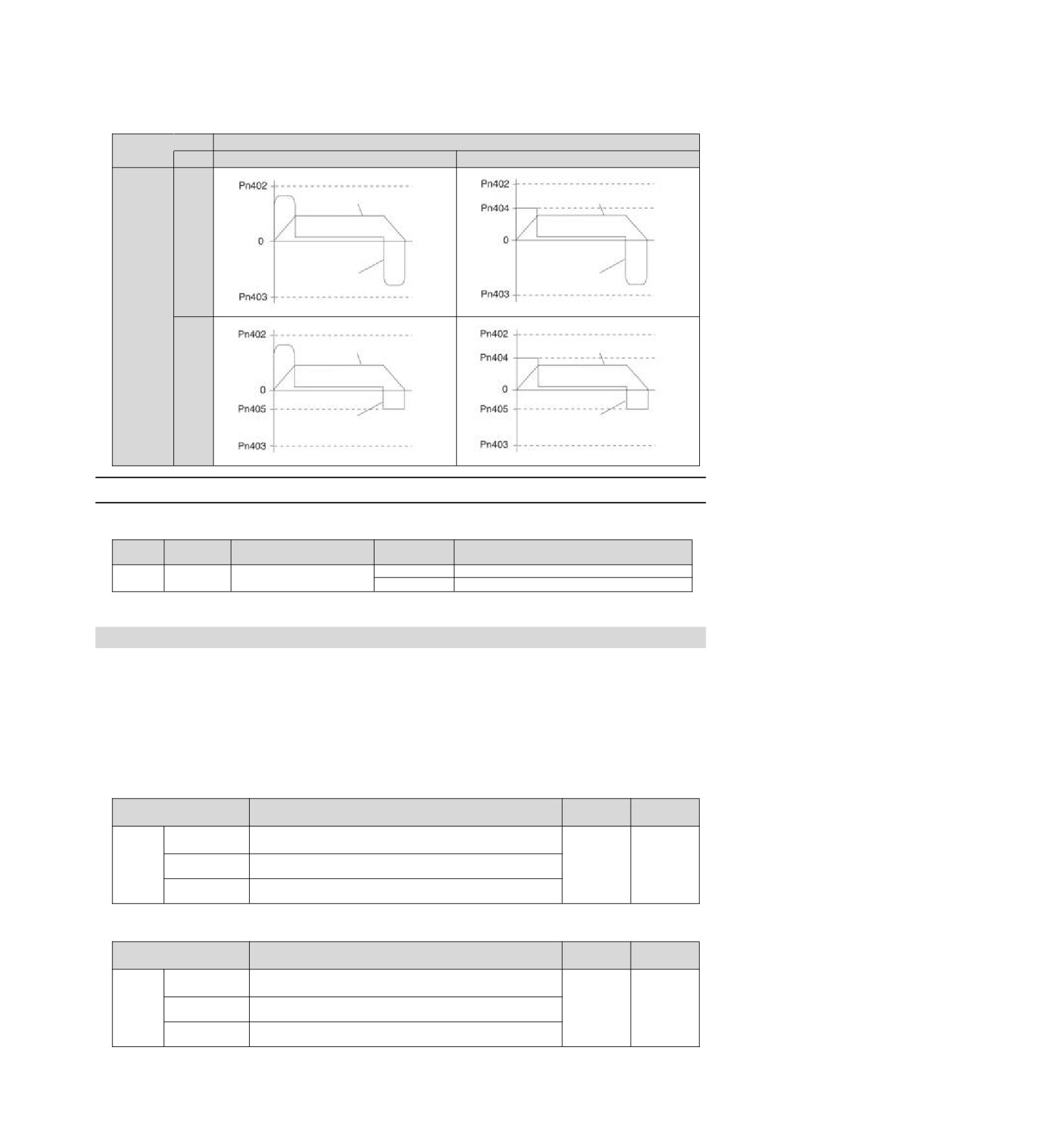
Indicates the output torque when the internal torque limit is set to 800%.
The rotation direction of the motor is set to Pn000 = n.0 (with CCW direction as forward rotation) as an
example.
/P-CL
Signal
State
OFF
ON
Speed
Speed
OFF
Torque
Torque
/N-CL
Speed
ON
Torque
Torque
6.7.3
Torque limit detection output (/CLT) signal
The /CLT signal indicating the motor output torque limit state is as follows.
Signal
Type
Connector pin number
Signal status
Meaning
name
ON (closed)
The motor output torque is limited.
Input
/CLT
Distribution required
OFF (OFF)
The motor output torque is not limited
(Note) /CLT signal needs to be distributed. It can be set to Pn50F = n.X (distribution of torque limit output (/CLT) signal) and
distributed to terminals.
6.8 Absolute position
The absolute value encoder will still remember the current position of the stop position after the power supply
is turned OFF.
In a system using an absolute value encoder, the current position can be grasped by an upper controller.
Therefore, when the system is powered on, there is no need to perform the origin reset operation.
There are three encoders for servo motors. Each encoder can be specified by setting Pn002 = n.X.
y Parameter Setting When Using Incremental Encoder
Effective
Parameter
Meaning
Category
time
n.0
Used as incremental encoder.
[Factory setting]
No battery is required.
Used as incremental encoder.
Power
Pn002
n.1
Setup
No battery is required
restart
Used as 1 coil absolute value encoder.
n.2
No battery is required.
yParameter setting when using 1-turn absolute value encoder
Effective
Parameter
Meaning
Category
time
n.0
Used as 1 coil absolute value encoder.
[Factory setting]
No battery is required.
Used as incremental encoder.
Power
Pn002
n.1
Setup
No battery is required
restart
Used as 1 coil absolute value encoder.
n.2
No battery is required.
50
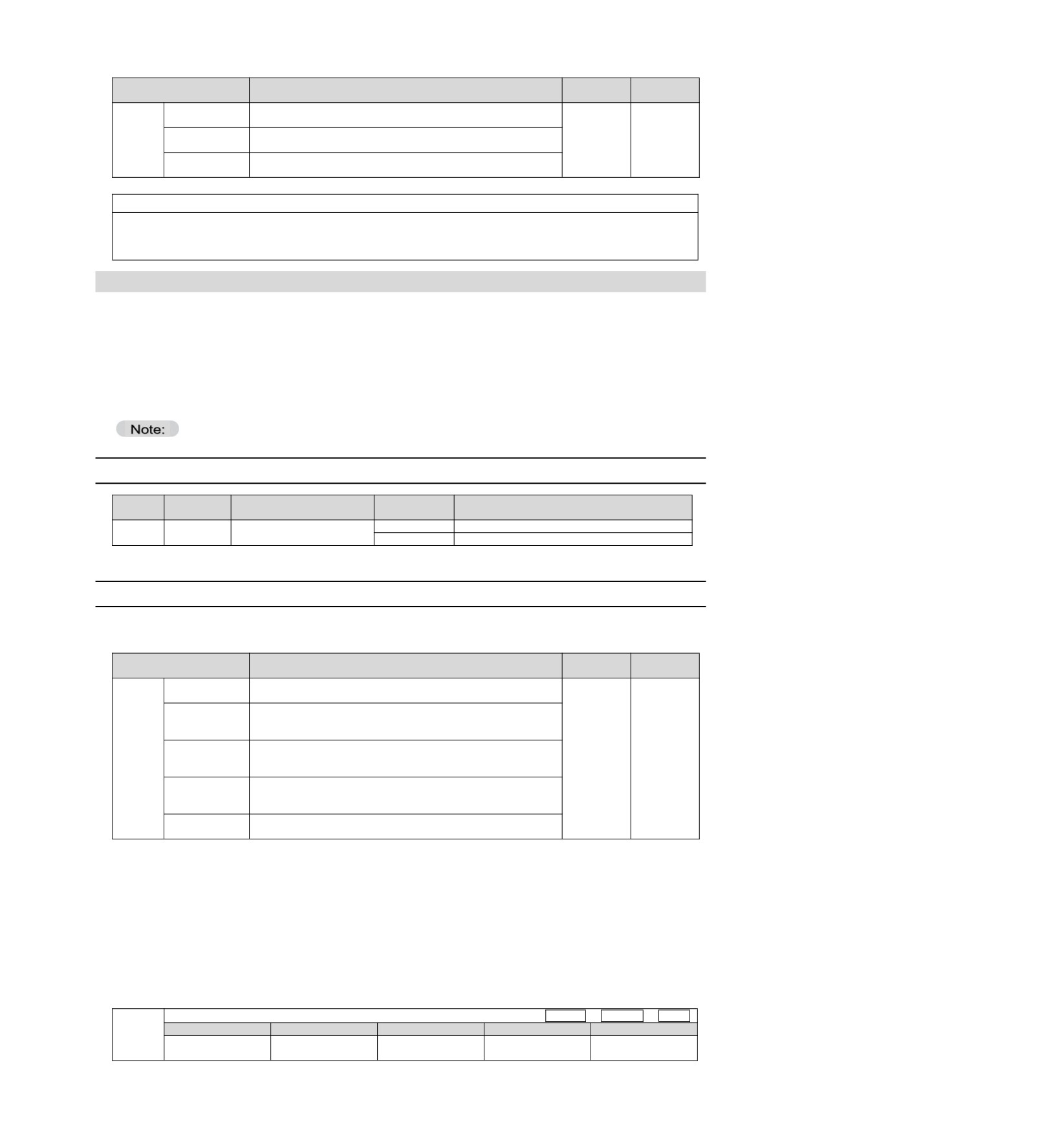
y Parameter setting when using multiple coil absolute value encoder
Effective
Parameter
Meaning
Category
time
n.0
Used as multiple coils absolute value encoder.
[Factory setting]
A battery is needed.
Used as incremental encoder.
Power
Pn002
n.1
Setup
No battery is required
restart
Used as 1 coil absolute value encoder.
n.2
No battery is required.
Notice
y Please install the battery on either side of the upper device or encoder cable.
If batteries are installed on the upper device and encoder cable at the same time, a circulation loop will be formed
between the batteries, resulting in product damage or burning.
6.9 Forced stop function
The forced stop function refers to the function of forcibly stopping the servo motor by a signal from an upper
device or an external device.
When forced stop is used, distribution of the forced stop input (FSTP) signal (Pn516 = n.X) is required.
There are three methods for stopping the motor: dynamic brake (DB) stop, free running stop and deceleration
stop.
(Note) The forced stop function is different from the hardware base blocking (HWBB) function and is not a function specified in the
safety standard. Please note.
Panel display and operator display
When forced to stop, "FSTP" will be displayed on the panel display and the digital operator.
6.9.1
Forced Stop Input (FSTP) Signal
Signal
Type
Connector pin number
Signal status
Meaning
name
ON (closed)
Driveable (normal operation)
Input
FSTP
Distribution required
OFF (OFF)
The motor stopped running.
(Note) FSTP signal needs to be distributed. It can be distributed to terminals through Pn516 = n.X (distribution of forced stop
input (FSTP) signal).
6.9.2
Selection of Stop Method for Forced Stop Function
The stop method of the forced stop function is selected through Pn00A=n. X (stop method at forced
stop).
Effective
Parameter
Meaning
Category
time
DB stop or free operation stop (stop method is the same as
n.0
Pn001 = n.X).
n.1
The set torque of Pn406 is used as the maximum torque to
[Factory
decelerate and stop the motor. The state after stopping
setting]
depends on the setting of Pn001 = n.X.
The set torque of Pn406 is taken as the maximum torque to
Power
Pn00A
n.2
decelerate and stop the motor, and then enter the free running
Setup
restart
state.
According to the deceleration time of Pn30A, the motor is
n.3
decelerated and stopped. The state after stopping depends on
the setting of Pn001 = n.X
According to the deceleration time of Pn30A, the motor will
n.4
decelerate and stop, and then enter the free running state.
(Note) During torque control, deceleration cannot be stopped. According to the setting of Pn001 = n. X (servo OFF and stop
method in case of Gr.1 alarm), the dynamic brake stops or the free operation stops.
When the emergency stop torque (Pn406) is set to stop the servo motor
When the emergency stop torque is set to stop the servo motor, Pn406 (Emergency Stop Torque) is set.
When Pn001=n.X is set to 1 or 2, the servo motor will be decelerated with the set torque of Pn406 as the
maximum value.
The factory setting is "800%". This is a large enough value to ensure that the servo motor must output
maximum torque. However, the actual effective maximum limit of emergency stop torque is the maximum
torque of the servo motor.
Emergency stop torque
Speed
Position
Torque
Setting range
Setting Unit
Factory setting
Effective time
Category
Pn406
Effective
0~800
1% *
800
Setup
immediately
51
* Percentage relative to rated torque of motor.
When the servo motor is stopped by setting the deceleration time (Pn30A) during
servo OFF and forced stop
When setting the deceleration time of the servo motor to stop the servo motor, Pn30A (deceleration time at
servo OFF and forced stop) is set.
Deceleration Time for Servo OFF and Forced Stop
Speed
Position
Torque
Setting range
Setting Unit
Factory setting
Effective time
Category
Pn30A
Effective
0~10000
1 ms
0
Setup
immediately
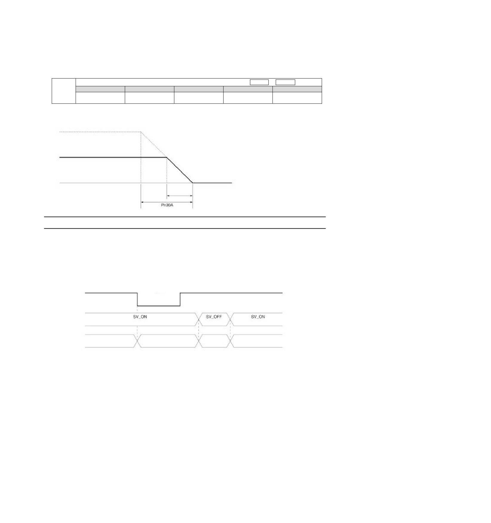
When Pn30A is set to "0", zero speed stops.
The deceleration time set by Pn30A is the time from the highest speed of the motor to the stop of the motor.
Maximum speed
Actual deceleration time =Actionspeed
x Deceleration Time (Pn30A)
Maximum speed
Action speed
Actual
deceleration
time
6.9.3
Methods of Recovery from Compulsory Stop
The recovery method when the operation is stopped by the forced stop input (FSTP) signal is as follows.
If a servo ON (SV_ON) command is received when the forced stop input (FSTP) signal is OFF, the forced stop
state will remain unchanged even if the FSTP signal is set to ON.
Enter the servo OFF (SV_OFF) command, and after entering the base blocking (BB) state, please enter the
servo ON (SV_ON) command again.
OFF (mandatory
ON (normal operation)
FSTP signal
ON (normal operation)
stop request)
M-III
command
Command
Command
Command
Status of
Force Stop Status
Running status
BB Status
Running status
servo units
FSTP Display
52
Chapter 7
Trial operation
Introduce the process and operation steps of the trial run and the functions that are convenient to use during
the trial run.
7.1 Commissioning process
7.1.1
Process of servo motor test run
The steps of the trial run are as follows.
Steps
Content
Settings and installation
Set the servo motor and servo drive according to the setting conditions. First
1
of all, confirm the action when there is no load. The servo motor is not
connected to the mechanical system here.
Wiring, connection
Connect to the servo drive.
2
Confirm the action of a single servo motor. Here, CN1 of servo drive is not
connected.
3
Confirmation before commissioning
4
Connect to the power
Setting of Absolute Value Encoder
5
This setting is made when only servo motors with absolute value encoders
are used.
7.2 Inspection and Precautions Before Commissioning
In order to carry out the trial run safely and correctly, please confirm the following items before the trial run.
y The setting, wiring and connection of servo drive and servo motor have been carried out correctly.
y The power supply voltage for servo drive is normal.
y The fastening parts of the servo motor are not loose.
y When using servo motor with oil seal, the oil seal is not damaged. And oil has been applied.
y When using servo motors stored for a long time, the maintenance and inspection of servo motors have been
completed.
y For the maintenance and inspection essentials of servo motor, please refer to the manual for using servo
motor.
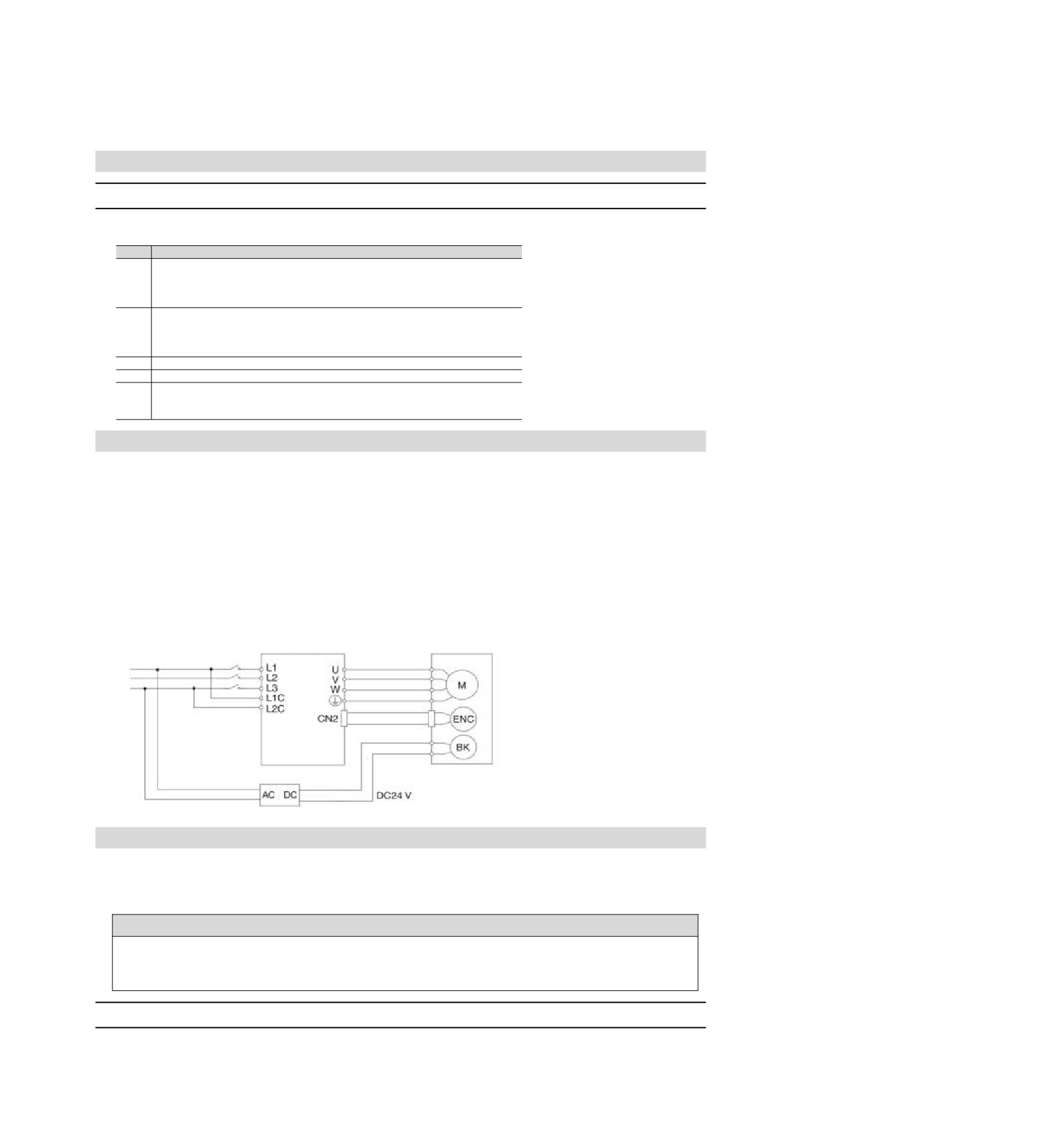
y Servo motors with brakes have previously released the brakes. When releasing the brake, the specified
voltage (DC24 V) must be applied to the brake. Examples of circuits for commissioning are as follows.
Servo motor
Servo unit
with brake
Power supply
24V power or brake power
7.3 Commissioning of Servo Motor Unit
The JOG operation function is used during the trial operation of the servo motor unit.
JOG operation refers to the function of driving the servo motor at the preset JOG speed (rotation speed)
without connecting the upper device and confirming the action of the servo motor.
! Notes
The over-travel prevention function is invalid during JOG operation. At the same time of operation, the operating
range of the machine must be considered.
7.3.1
Confirmation before execution
To run JOG, the following confirmation must be made in advance.
y The write inhibit setting of the parameter is not set to "write inhibit".
53
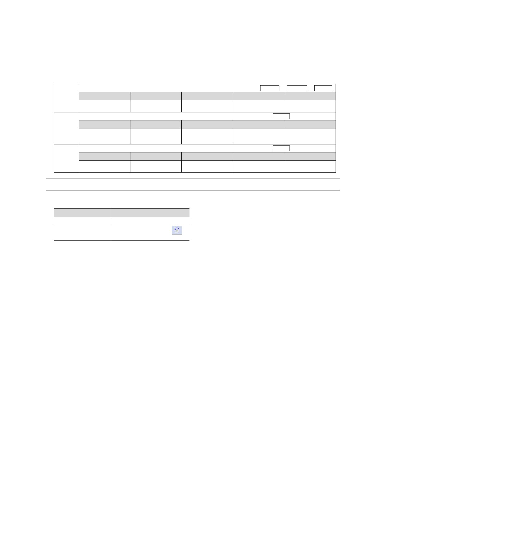
y The main circuit power supply must be ON.
y No alarm has occurred.
y Hardware Base Blocking (HWBB) function must be invalid.
y Must in servo OFF state.
y The setting of JOG speed must take into account the operating range of the machine used.
Set the JOG speed through the following parameters.
Jog (JOG) speed
Speed
Position
Torque
Setting range
Setting Unit
Factory setting
Effective time
Category
Pn304
Effective
0~10000
1 min-1
500
Setup
immediately
Soft start acceleration time
Speed
Setting range
Setting Unit
Factory setting
Effective time
Category
Pn305
Effective
0~10000
1 ms
0
Setup
immediately
Soft start deceleration time
Speed
Setting range
Setting Unit
Factory setting
Effective time
Category
Pn306
Effective
0~10000
1 ms
0
Setup
immediately
7.3.2
Operable tool
The executable operations for JOG operation are as follows
Operating tool
Distribution
Panel operator
Fn002
iWatch+ debugging
[JOG Operation]
software
54