HSD7-E Series AC Servo Drive. User's Manual (Version: V0.1) - page 1
Introduction
This manual describes the information required for the selection of HSD7 series AC servo drivers, the design
of servo drivers, trial operation, adjustment, operation and maintenance. To correctly use the HSD7 series AC
servo driver, please read this manual carefully.
Please take good care of this manual so that it can be read and referenced at any time when necessary.
How to use the manual
The basic terminology used in this manual
The terms used in this manual are described below.
Basic terms
Meaning
Servo driver
HSD7 series servo driver
Servo motor
S, SA, SC series servo motors
Servo drive
Servo driver and servo motor combination
A servo control system that includes the combination of a Servo Drive with a host
Servo system
设置格式[周]: 字体颜色: 自动设置
controller and peripheral devices.
Servo ON
Supplying power to the motor.
设置格式[周]: 字体颜色: 自动设置
Servo OFF
Not supplying power to the motor.
A state in which the motor is stopped and is in a position loop with a position
设置格式[周]: 字体颜色: 自动设置
Servo lock
reference of 0.
设置格式[周]: 字体颜色: 自动设置
Cables connected to main circuit terminals (main circuit power cable, control power
Main loop cable
cable, servo motor main circuit cable, etc.)
Labeling of icons
The following icons are designed in this book to make readers understand the distinction between the
contents of the commands. And use these icons where necessary.
Indicates precautions and restrictions that must be observed.
Meanwhile, it also indicates that an alarm will be raised, but it will not cause damage to the device.
Important
Indicates the explaining of difficult terms and explaining the terms that have not been explained in advance.
Terminology
explanation
Case
Indicates examples of operations or settings, etc.
Supplementary
Indicates additional items or information that is helpful to use after understanding.
notes
Precautions for safety
Safety-related warning signs
The following identification terms are used in this manual to explain matters to be observed in preventing
casualties and equipment damage. Distinguish the hazards and damages caused by misoperation through
identification terms. The contents are all important contents related to safety. Please observe them.
! Danger
Indicates an emergency situation that is likely to result in death, serious injury and fire if not avoided.
! Warning
Indicates a dangerous situation that may lead to death, serious injury and fire if not avoided.
! Notes
Indicates a dangerous situation that may lead to moderate, minor injuries and fire if not avoided.
Notice
Indicates a hazardous condition that may cause equipment damage if not avoided.
Table of contents
Chapter 1 Basic Information of Servo Drive
1
1.1 HSD7 Series AC Servo Driver
1
1.2 Distinguishing Method of Nameplate
1
1.3 Model Description
2
1.3.1 Servo drive model description example
2
Chapter 2 Selection of Servo Drive
3
2.1 Ratings and specifications
3
2.1.1 Rating value
3
2.1.2 Specification table
4
2.2 Overall dimensions of servo driver
5
Chapter 3 Installation of servo drive
7
3.1 Precautions for setting
7
3.2 Mounting Types and Orientation
7
3.3 Mounting hole dimensions
7
3.4 Installation interval
7
Chapter 4 Connection of Servo Unit
8
4.1 Wiring and Connecting precautions
8
4.1.1 General precautions
8
4.1.2 Anti-interference countermeasures
9
4.1.3 Grounding
13
4.2 Basic connection diagram
14
4.3 Power supply wiring for servo drive
14
4.3.1 Terminal symbol and terminal name
14
4.3.2 Wiring Operation Steps of Main Loop Connector
15
4.3.3 Power on sequence control
15
4.3.4 Power wiring diagram
16
4.3.5 Connection of Regenerative Resistance
16
4.4 Servo motor connection
17
4.4.1 Terminal symbol and terminal name
17
4.4.2 Pin Arrangement of Connector (CN2) for Encoder
17
4.4.3 Connection of Servo Drive and Encoder
17
4.4.4 Wiring of Servo Drive and Brake
18
4.5 Connection of input and output signals
19
4.5.1 Name and function of input/output signal connector (CN1)
19
4.5.2 Pin Arrangement of Input and Output Signal Connector (CN1)
19
4.5.3 Examples of wiring for input and output signals
20
4.5.4 Input-output loop
22
Chapter 5 Basic functions to be set before operation
24
5.1 Operation of Parameters (Pn)
24
5.1.1 Classification of the parameter
24
5.1.2 Writing Method of Parameters
24
5.1.3 How to Set Parameters
25
5.1.4 Write inhibit setting of parameters
25
5.1.5 Initialization of parameter settings
25
5.2 Setting of Communication Specifications for MECHATROLINK-II
25
5.2.1 Communication specification setting
25
5.2.2 Station address setting
25
5.3 Setting of Communication Specifications for MECHATROLINK-III
25
5.3.1 Communication specification setting
25
5.3.2 Station address setting
26
5.4 Setting of EtherCAT communication specifications
26
5.4.1 Setting of Communication Specifications
26
5.4.2 Station address setting
26
5.5 Setting of Power Supply Types for Main Circuit and Control Circuit
26
5.5.1 Setting of AC Power Input/DC Power Input
26
5.5.2 Setting of Single-Phase AC Power Input/Three-Phase AC Power Input
27
5.6 Function and setting of servo ON input (/S-ON) signal
27
5.6.1 Function of servo ON input (/S-ON) signal
27
5.6.2 Set to Constant Servo ON (Motor Energized)
27
5.7 Setting of Motor Rotation Direction
27
5.8 Functions and settings of over-travel prevention
28
5.8.1 Overtravel signal
28
5.8.2 Select whether the over-travel prevention function is valid/invalid
29
5.8.3 Selection of Motor Stopping Method for Over-travel Prevention Function
29
5.8.4 Overtravel warning function
30
5.9 Brake
30
5.9.1 Action sequence of brake
31
5.9.2 Brake Control Output (/BK) Signal
31
5.9.3 Output Time of Brake Control Output (/BK) Signal when Servo Motor Stopped
33
5.9.4 Output Time of Brake Control Output (/BK) Signal in Servo Motor Rotation
33
5.10 Servo OFF and Motor Stop Method in Alarm
34
5.10.1 Motor Stop Method when Servo OFF
34
5.10.2 Motor stopping method when alarm occurs
34
5.11 Motor overload detection value
35
5.11.1 Detection time of overload warning (A.910)
35
5.11.2 Detection time of overload alarm (A.720)
36
5.12 Setting of Electronic Gear
36
5.12.1 Setting of Electronic Gear Ratio
36
5.12.2 Setting Examples of Electronic Gear Ratio
37
5.13 Setting of Absolute Value Encoder
37
5.13.1 Precautions in Setting (Initializing)
37
5.13.2 Confirmation before execution
38
5.13.3 Operable tool
38
5.14 Setting of Regenerative Resistance Capacity
38
Chapter 6 Application function
39
6.1 Distribution of input and output signals
39
6.1.1 Distribution of input signals
39
6.1.2 Distribution of output signals
40
6.1.3 Servo Alarm Output (ALM) Signal
40
6.1.4 Warning output (/WARN) signal
40
6.1.5 Rotation detection output (/TGON) signal
40
6.1.6 Ready output (/S-RDY) signal
41
6.1.7 Speed consistent output (/V-CMP) signal
41
6.1.8 Positioning Completion (/COIN) Signal
42
6.1.9 Position nearby output (/NEAR) signal
42
6.1.10 Speed limit function during torque control
43
6.2 Operation for Momentary Power Interruptions
44
6.3 SEMI F47 Specification Support Function
44
6.4 Setting of Maximum Speed of Motor
46
6.5 Encoder frequency division pulse output
46
6.5.1 Signal output by encoder frequency division pulse
46
6.5.2 Setting of Encoder frequency division pulse output
47
6.6 Soft limit function
49
6.6.1 The valid/invalid choice of soft limit function
49
6.6.2 Setting of soft limit value
49
6.6.3 Carry out soft limit check according to commands
49
6.7 Selection of torque limit
49
6.7.1 Internal torque limit
50
6.7.2 Exterior torque limit
50
6.7.3 Torque limit detection output (/CLT) signal
51
6.8 Absolute position
51
6.9 Forced stop function
52
6.9.1 Forced Stop Input (FSTP) Signal
52
6.9.2 Selection of Stop Method for Forced Stop Function
52
6.9.3 Methods of Recovery from Compulsory Stop
53
Chapter 7 Trial operation
54
7.1 Commissioning process
54
7.1.1 Process of servo motor test run
54
7.2 Inspection and Precautions Before Commissioning
54
7.3 Commissioning of Servo Motor Unit
54
7.3.1 Confirmation before execution
54
7.3.2 Operable tool
55
Chapter 8 Panel Display and Use of Panel Operators
56
8.1 Panel operator
56
8.1.1 Name and function of panel operator keys
56
8.1.2 Switching of functions
56
8.1.3 Status display mode
57
8.2 Operation of Parameters (PA) in Panel Operator
58
8.2.1 Setting Method of "Numerical Setting Type"
58
8.2.2 Setting Method of "Function Selection Type"
59
8.3 The operation of the monitor display (Un) in the panel operator
59
8.3.1 Basic operation of monitoring display
60
8.3.2 Monitoring of input and output signals (Un005/ Un006)
60
8.4 Operation of Auxiliary Function (FA) in Panel Operator
61
8.4.1 Display of alarm records (FA000)
61
8.4.2 JOG operation (FA002)
61
8.4.3 Origin search (FA003)
62
8.4.4 Program JOG run (FA004)
62
8.4.5 Initialization of parameter settings (FA005)
63
8.4.6 Deletion of Alarm records (FA006)
63
8.4.7 Absolute value encoder Setup(initialization)(FA008)
63
8.4.8 Automatic Adjustment of Analog (Speed and Torque) Command Bias (FA009)
64
8.4.9 Manual Adjustment of Speed Command Bias (FA00A)
64
8.4.10 Manual Adjustment of Torque Command Bias (FA00B)
64
8.4.11 Automatic Adjustment of Offset of Motor Current Detection Signal(FA00E)
65
8.4.12 Write inhibit setting of parameters(FA010)
65
8.4.13 Displays the motor model (FA011)
65
8.4.14 Display software version (FA012)
66
8.4.15 Single parameter adjustment (FA203)
66
8.4.16 EasyFFT(Fn206)
67
8.4.17 Load Inertia/Mass Detection (FA208)
68
Chapter 9 Maintenance
69
9.1 Inspection and component replacement
69
9.1.1 Inspection
69
9.1.2 Battery Replacement
69
9.2 Alarm display
70
9.2.1 Warning list
70
9.2.2 Cause of Alarm and Treatment Measures
72
9.2.3 Alarm reset
78
9.2.4 Display of alarm records
78
9.2.5 Deletion of Alarm records
78
9.3 When warning is displayed
78
9.3.1 Warning list
78
9.3.2 Reasons for Warning and Countermeasures
80
9.4 Monitoring of communication data when alarms and warnings occur
81
9.5 The fault causes and treatment measures can be judged from the actions and states of servo motors
81
Chapter 10 List of parameter
85
10.1 List of servo parameters
85
10.1.1 Method for distinguishing the list
85
10.1.2 List of servo parameters
86
Chapter 11 Operation of Debugging Software (iWatch+)
111
11.1 Connection and login of iWath+ debugging software
111
11.2 Automatic adjustment (no upper command)
111
Motor code is written to encoder EEROM operation(FA301)
114
Motor zero position check and reset operation (FA300)
115
Chapter 1
Basic Information of Servo Drive
1.1 HSD7 Series AC Servo Driver
HSD7 series servo drive is mainly used for occasions requiring "high speed, high frequency and high
positioning accuracy". The servo drive can maximize the performance of the machine in the shortest possible
time and help to improve production efficiency.
HSD7 series servo drivers include single-axis HSD7-ES(BS) series servo drivers and double-axis HSD7-EW
(BW)series servo drivers.
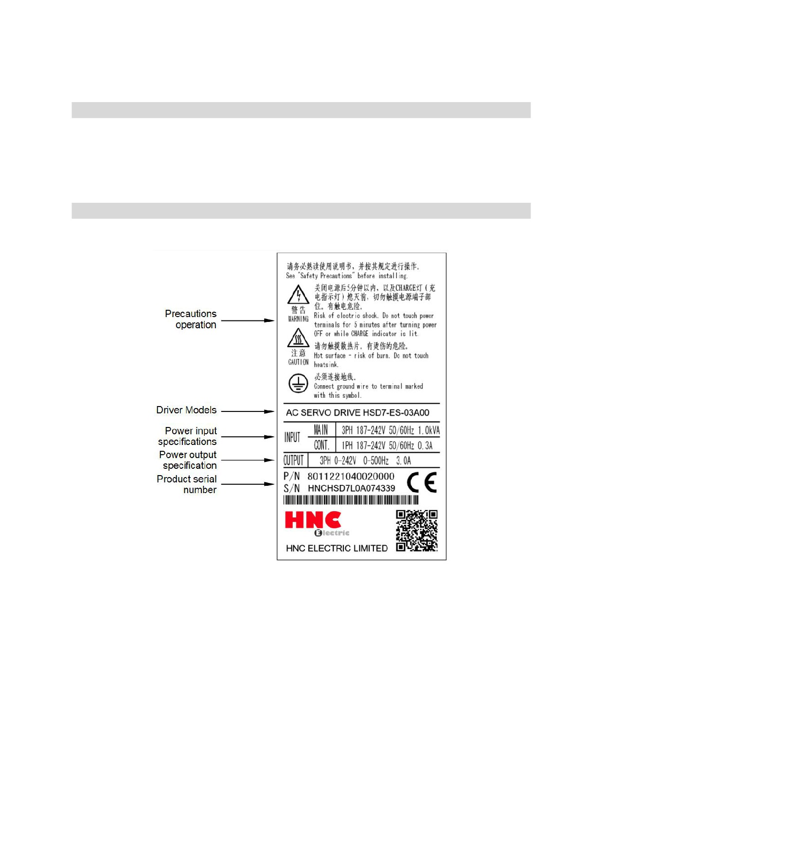
1.2 Distinguishing Method of Nameplate
The basic information marked on the drive nameplate is shown in the following figure.
1
1.3 Model Description
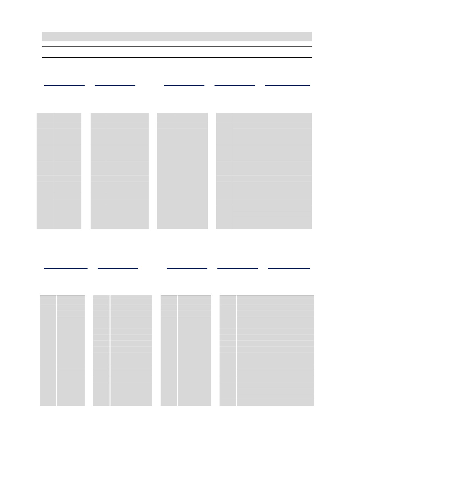
1.3.1
Servo drive model description example
■ Three-phase 220VAC
_
_
HSD7
ES
10
A
00
HSD7 Series
Axis
Continuous Output
Power
Interface
Number
Current
Supply Voltage
Type
Axis Number
Contionous Output Current
Power Supply Voltage
Interface Type
S
Single
03
3.0 A
A
220VAC
00
Analog (standard resolution)/Pulse
Axis
06
6.5 A
08
8.5 A
01
CANopen Communications
W Double
10
10.5 A
Axis
05
Analog (high resolution )/Pulse
12
12 A
10
MECHATROLINK-Ⅱ
16
16A
Communications
25
25 A
20
MECHATROLINK-Ⅲ
Communications
30
EtherCAT Communications
* The maximum specification of continuous output current for biaxial drive is 10.
■ Three-phase 380VAC
_
HSD7
--
ES
15
D
00
HSD7 Series
Axis
Continuous Output
Power
Interface
Number
Current
Supply Voltage
Type
Axis Number
Contionous Output Current
Power Supply Voltage
Interface Type
S
Single
15
15 A
D
380VAC
00
Analog (standard resolution )/Pulse
Axis
18
18 A
24
24 A
01
CANopen Communications
35
35 A
05
Analog (high resolution)/Pulse
10
MECHATROLINK-Ⅱ
Communications
20
MECHATROLINK-Ⅲ
Communications
30
EtherCAT Communications
* Servo motor model commands refer to the current product selection sample book
2
Chapter 2
Selection of Servo Drive
2.1 Ratings and specifications
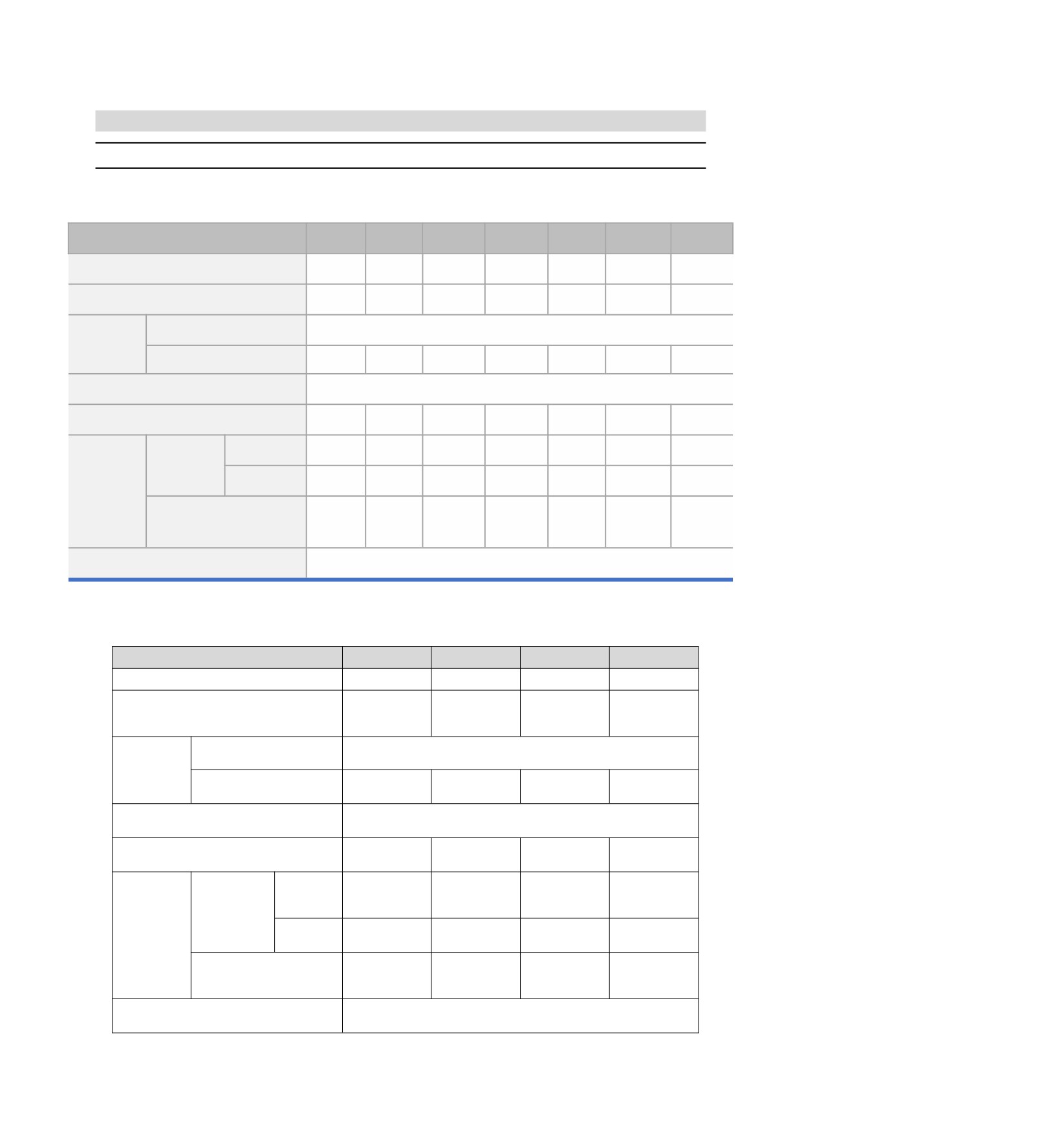
2.1.1
Rating value
■ Three-phase 220VAC
Model
03A□□
06A□□
08A□□
10A□□
12A□□
16A□□
25A□□
Continuous Output Current[Arms]
3
6.1
8.5
10
12
16.0
25.0
Instantaneous Max. Output Current [Arms]
10.6
14.1
21.2
24.8
29.7
49.5
63.6
AC220V,-15% to +10%,
Power Supply
50 Hz / 60 Hz
Main Circuit
Input Current[Arms]
1.9
3.9
5.4(14.3)
6.3(16.8)
7.6
10.1
15.7
(5.1)
(10.3)
AC220 V, -15% to +10%,
Control Power Supply
50 Hz / 60 Hz
Power Supply Capacity*[kVA]
0.9(2.1)
1.7(4.2)
2.4(5.8)
2.8(6.8)
3.4
4.0
5.9
Resistance[Ω]
Built-In
——
40
20
20
20
12
20
Regenerative
Resistor
Capacity[W]
——
80
80
80
80
150
120
Regenerative
Resistor
Minimum Allowable
External Resistance[Ω]
40
20
15
15
15
15
10
Overvoltage Category
III
■ Three-phase 380VAC
Model No.
15D
18D
24D
35D
Continuous output current [Arms]
15
18
24
35
Maximum instantaneous output current
35.3
44.1
58.9
88.3
[Arms]
AC30V,-15% ~ +10%,
Input power requirements
Main power
50 Hz / 60 Hz
supply
Input current [Arms]
8.6
14.5
21.7
31.8
Input control power requirements
DC 24V,-10% ~ +10%,
Input power capacity [kVA]
7.1
11.7
14.4
21.9
Resistance
32
23
-
-
Built-in
[Ω]
regenerative
resistor
Regenerative
Power [W]
150
150
-
-
resistor
Minimum allowable external
32
32
23
16
resistance [Ω]
Overvoltage category
III
3
2.1.2
Specification table
Item
Specifications
Control model
Position control, JOG operation, Speed contacts, etc.
Encoder feedback
Serial data encoder: 17-bit or 23-bit (single or multiple turns)
Operating ambient
temperature/storage
Operating ambient temperature: 0~+50℃, storage temperature: -20~+85℃
temperature
Conditions of use
Ambient humidity/storage
Below 90%RH (no freezing or condensation)
humidity
Vibration/impact strength
4.9m/s2/19.6m/s2
Structure
Base mounting type
1:10000 (the lower limit of the speed control range is stable operation without crawling under rated
Speed control range
load)
Speed response
3.1KHz
Speed Volatility (Load
0 ~ 100% load: Under ±0.01%(at rated speed)
Performance
Change)
Velocity fluctuation rate
Rated voltage ±10%: 0% (at rated speed)
(voltage change)
Velocity fluctuation rate
25±25℃:Below ±0.1%(at rated speed)
(temperature change)
Command voltage
DC±10V
Analog speed
Input impedance
Around 20KΩ
command input
Circuit time parameter
47μs
Command voltage
DC±10V
Analog torque
Input impedance
Around 20KΩ
command input
Circuit time parameter
47μs
Point
8 points
Servo ON (/S-ON), P action (/P-CON), prohibition of forward rotation side drive (P-OT), prohibition
Sequential control
of reverse rotation side drive (N-OT), alarm reset (/ALM-RST), forward rotation side torque limit
input signal
Function (assignable)
(/P-CL), reverse rotation side torque limit (/N-CL), position deviation reset (/CLR), internal set
speed switching, etc.
Distribution of the above signals and change of positive/negative logic can be performed
Point
6 points
Servo Alarm (ALM), Positioning Complete (/COIN), Speed Consistent Detection (/V-CMP), Servo
Sequential control
Motor Rotation Detection (/TGON), Servo Ready (/S-RDY), Torque Limit Detection (/CLT), Brake
output signal
Function (assignable)
(/BK), Encoder Zero Output (PGC)
Distribution of the above signals and change of positive/negative logic can be performed
Encoder frequency division pulse output
Phase A, phase B, phase C: linear drive output; Frequency division pulse number: can be
arbitrarily set
Communication protocol
MODBUS
RS-485
1: N communication
The maximum can be N = 127 stops.
communication
Axis address setting
Through parameter setting
Communication protocol
CANOpen (DS301+DS402 line gauge)
CAN communication
1: N communication
The maximum can be N = 127 stops.
Axis address setting
Through parameter setting
Communication protocol
MECHATROLINK-II
Set slave address
41 to 5F (hexadecimal) (maximum number of slave stations supported: 30), via parameter setting
MECHATROLINK-Ⅱ
Baud rate
10 Mbps, 4 Mbps, via parameter setting
Bus
Transmission period
250 microseconds or 0.5 milliseconds to 4.0 milliseconds (multiples of 0.5 milliseconds)
Number of bytes transferred
There are 17 or 32 bytes for each site and the same is set by parameters
Communication protocol
MECHATROLINK-III
Set slave address
03 to EF (hexadecimal) (maximum number of slave stations supported: 62), via parameter setting
MECHATROLINK-Ⅲ
Baud rate
100 Mbps
Bus
250 microseconds, 500 microseconds, 750 microseconds, or 1.0 milliseconds to 4.0 milliseconds
Transmission period
(multiples of 0.5 milliseconds)
Number of bytes transferred
There are 16, 32 or 48 bytes for each site and the same is set by parameters
Communication protocol
CoE (CANOpen over EtherCAT)
Control model
csp, pp, hm, csv, cst, pv, tq
EtherCAT bus
Zero return mode
1-14, 17-30, 33, 34, 35, 37
Synchronization mode
DC, SM2, FreeRun
Minimum command cycle
125 μs
Display function
CHARGE Indicator, 7-segment Digital Tube 5-bit
Regeneration treatment
Internal Regenerative Resistor or External Regenerative Resistor (Optional)
Overtravel (OT) prevention function
Dynamic brake (DB) stops, deceleration stops or free running stops when P-OT and N-OT input
actions are performed.
Protection function
Overcurrent, overvoltage, undervoltage, overload, overspeed, regeneration fault, encoder
feedback error, etc.
Monitoring function
Revolving speed, current position, command pulse accumulation, position deviation, motor
current, running state, input and output signals, etc.
Auxiliary function
Gain adjustment, alarm recording, JOG operation, origin search, inertia detection, etc.
Intelligent function
Built-in Gain Auto Tuning
Applicable load inertia
Less than 5 times of motor inertia
Feedforward compensation
0 ~ 100% (set unit 1%)
Symbol+pulse sequence, CW+CCW pulse sequence, 90 °phase difference two-phase pulse
Type of input pulse
(phase A+phase B)
Input pulse form
Support linear drive, open collector
y Linear drive
Position control
Symbol+pulse sequence, CW+CCW pulse sequence: 500K pps
Maximum input pulse
90° phase difference two-phase pulse (phase A+phase B): 500K pps
frequency
y Open collector
Symbol+pulse sequence, CW+CCW pulse sequence: 200K pps
90° phase difference two-phase pulse (phase A+phase B): 200K pps
4

2.2 Overall dimensions of servo driver
◆ HSD7-03A
5
2×M4
40
170
35
5
单位:毫米
安装孔图
Unit : mm
Mounting Hole Diagram
◆ HSD7-06A
6
58±0.5
3×M4
(安装间距)
(mounting pitch)
70
180
6
64
单位:毫米
安装孔图
Unit : mm
Mounting Hole Diagram
◆ HSD7-10A
6
78±0.5
3×M4
(安装间距)
(mounting pitch)
90
180
6
84
单位:毫米
安装孔图
Unit : mm
Mounting Hole Diagram
5
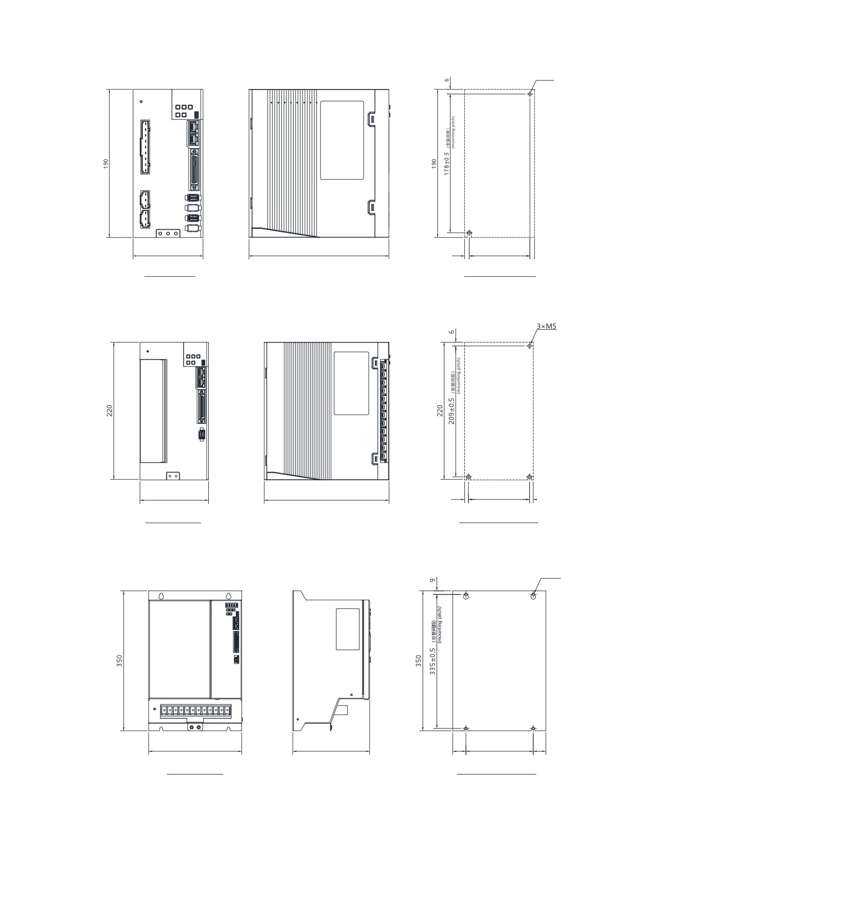
◆ HSD7-03/06/10A
2×M5
90
180
6
78±0.5
6
(安装间距)
(mounting pitch)
单位:毫米
安装孔图
Unit : mm
Mounting Hole Diagram
◆ HSD7-16A/HSD7DS-25A HSD7-15D/HSD7-18D
110
200
6
98±0.5
6
(安装间距)
(mounting pitch)
单位:毫米
安装孔图
Unit : mm
Mounting Hole Diagram
◆ HSD7-24D/HSD7-35D
4×M6
236
194
33
170
33
(安装间距)
(mounting pitch)
单位:毫米
安装孔图
Unit : mm
Mounting Hole Diagram
6
Chapter 3
Installation of servo drive
3.1 Precautions for setting
For the set environmental conditions, please refer to the following.
2.1.2 Specifications
■ When installed near the heating element
To make the temperature around the servo drive conform to the environmental conditions, please control the
temperature rise caused by the heat radiation or convection of the heating element.
■ When installed near a vibration source
Please install anti-vibration equipment on the installation surface of servo drive to prevent vibration from being
transmitted to servo drive.
■ Other
Do not set it in hot and humid places, places with water droplets or cutting oil splashing, places with more dust
or iron powder in ambient gas, places with corrosive gas and radiation fields.
3.2 Mounting Types and Orientation
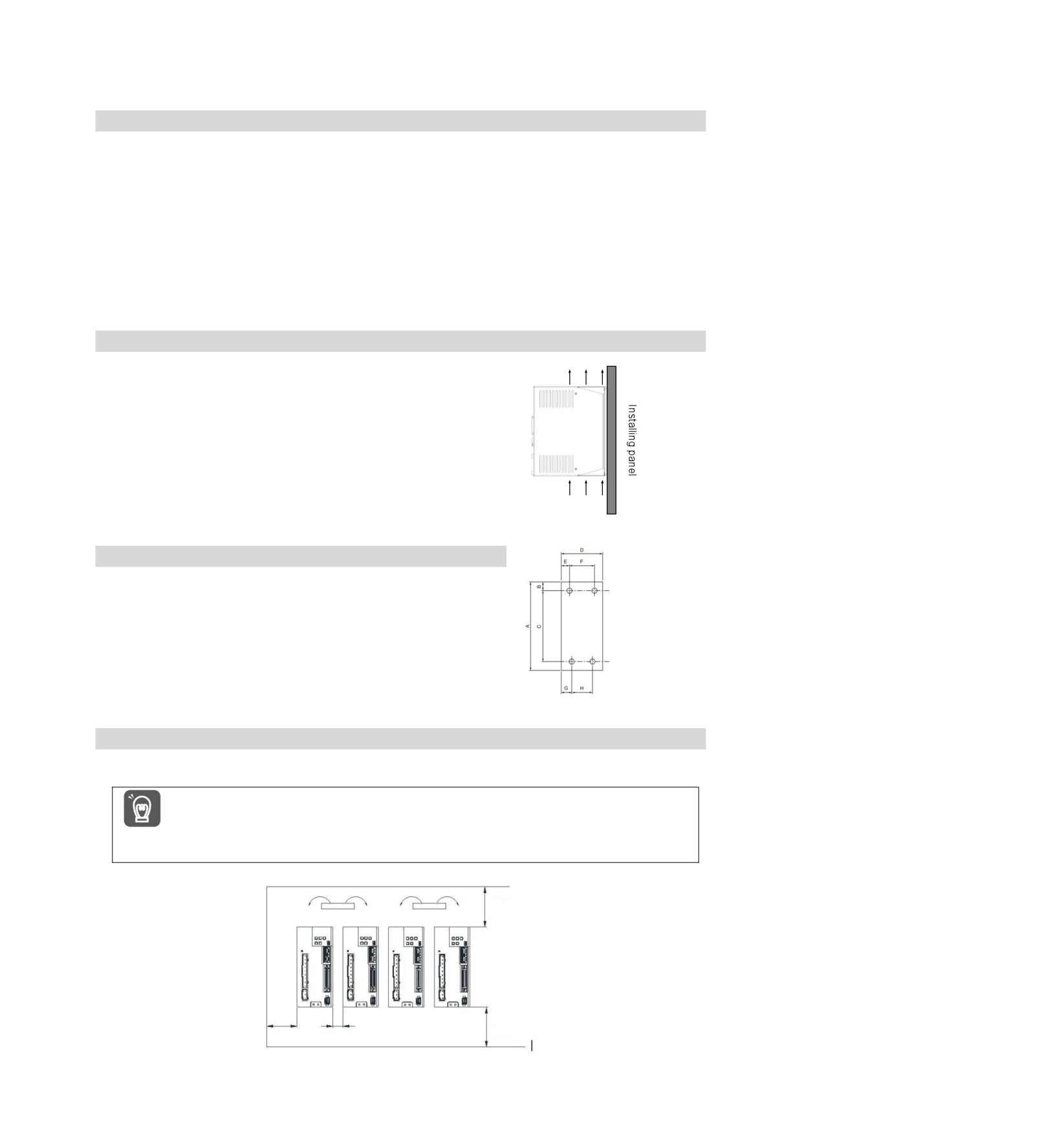
The servo driver can be installed in various ways, but in any case,
the servo driver must be installed in the vertical direction, as shown
in the right figure.
In addition, please make the front surface (panel display part) of
servo drive face the operator for installation.
(Note) Please firmly fix the servo drive on the mounting surface through 2 ~ 4
mounting holes (the number of mounting holes varies according to the
capacity).
Air convection direction
3.3 Mounting hole dimensions
Please use the mounting hole to firmly fix the servo drive on the
mounting surface.
Please refer to
2.3
outline dimensions of servo drive for specific
installation dimensions.
(Note) During installation, please prepare a screwdriver with a length greater than the
depth of servo drive.
3.4 Installation interval
Please ensure that the following intervals are left around the servo drive.
To prevent the ambient temperature of the servo drive from rising locally, please set a cooling fan on the
upper part of the servo drive. In addition, please refer to the figure below to leave enough space in order to
Important make use of fans and natural convection to cool the servo drive.
Fan
Fan
Above 40mm
Above 30mm Above 1mm
Above 40mm
7
Chapter 4
Connection of Servo Unit
4.1
Wiring and Connecting precautions
设置格式[侯]: 段落间距段前:
1
行
4.1.1
General precautions
! Danger
y Do not change the wiring during power-on.
Otherwise, it will lead to electric shock or injury.
! Warning
y Please be connected or checked by professional technicians.
Otherwise, it will lead to electric shock or product failure.
y Please carefully confirm the wiring and power supply.
The output circuit may be short-circuited due to wrong wiring and application of abnormal voltage. Mechanical
damage or casualties caused by the above failures.
y Please connect with designated terminals when AC power supply and DC power supply are connected with servo
drive.
y AC power supply should be connected to L1/L2/L3 terminal and L1C/L2C terminal of servo drive.
y Please connect DC power supply with B1/⊕ terminal and terminal of servo drive, L1C/L2C.
Failure to do so may result in failure or fire.
y Please connect the external dynamic brake resistor conforming to the specifications of machinery and devices
with the designated terminal when the servo drive uses the external dynamic brake option. Otherwise,
unexpected actions will be caused during emergency stop, causing equipment damage, burning damage and
personal injury.
! Notes
y Please confirm that the (CHARGE) lamp is off after the power supply is turned off for at least 5 minutes, and then
conduct wiring and inspection. Even if the power supply is turned off, high voltage may still remain inside the
servo drive. Therefore, do not touch the power terminal while the (CHARGE) lamp is on.
Otherwise, it will lead to electric shock.
y Please follow the precautions and procedures recorded in this manual for wiring and trial operation.
Servo drive failure caused by wrong wiring of brake circuit and application of abnormal voltage may lead to
mechanical damage or casualties.
y Please wire correctly and reliably.
The connector and the pin arrangement of the connector vary depending on the model. Please be sure to confirm
the pin arrangement through the technical data of the model used.
Otherwise, it will lead to product failure or misoperation.
y Please be sure to tighten and effectively connect the wires of the power supply terminal and the motor connection
terminal according to the specified method and torque. If it is not tightened sufficiently, the wires and terminal
blocks will heat up and cause fire due to poor contact.
y For input and output signal cables and encoder cables, please use shielded double stranded wires or multi-core
double stranded integrated shielded wires.
y When wiring the main loop terminal of servo drive, please observe the following precautions.
y After all wiring including the main loop terminals is completed, the servo drive power supply is switched on.
y When the main circuit terminal is of connector type, please remove the connector from the servo drive body and
wire again.
y Only one wire can be inserted into one wire socket of the main circuit terminal.
y When inserting wires, do not make burrs of core wires contact with adjacent wires to cause short circuit.
y Please set up safety devices such as circuit breakers for wiring to prevent external wiring from short-circuiting.
Otherwise, it will lead to fire or failure.
8
! Notice
y Please use the cables designated by our Company as far as possible when connecting.
Please confirm the rated current and operating environment of the model when using cables other than those
specified by our Company. Use the wiring materials designated by the Company or equivalent products.
y Please tighten the fixing screw and locking mechanism of cable connector.
If the fastening is not sufficient, the cable connector may fall off during operation.
y Do not use the same sleeve for high-voltage wires (main loop cables) and low-voltage wires (cables for input and
output signals and encoder cables), nor tie them together. Please keep a spacing of more than 30cm when wiring
when not placing strong and weak current wires into separate bushings.
It will cause misoperation due to interference of weak current wires if it is too close.
y Please install the battery on either side of the upper device or encoder cable.
If batteries are installed on the upper device and encoder cable at the same time, a circulation loop will be formed
between the batteries, resulting in product damage or burning.
y Pay attention to the polarity when connecting the battery.
Battery rupture can cause encoder failure.
! Important
y Please use circuit breakers or fuses for wiring to protect the main circuit.
The servo drive is directly connected to a commercial power supply without using transformers or the like for
insulation. To prevent the servo system from being mixed with the outside world, be sure to use circuit breakers
or fuses for wiring.
y Please set the leakage breaker.
Servo drive has no built-in ground short circuit protection loop. To build a safer system, please configure the earth
leakage breaker for overload and short circuit protection, or install the earth leakage breaker for short circuit
protection in combination with the circuit breaker for wiring.
y Please avoid frequently turning ON/OFF the power supply.
y Frequent ON/OFF power supply will lead to aging of internal components of servo drive, so do not frequently
ON/OFF power supply except for necessary applications.
y The power ON/OFF interval should be more than 1 hour (roughly standard) after starting the actual operation
(normal operation).
Please observe the following precautions when wiring to use the servo system safely and stably.
y Please use standard cables for each connecting cable. In addition, when designing and configuring the
system, please shorten the cable as much as possible.
y Please be careful not to bend or tighten it when the core diameter of signal cable is less than 0.3 mm2.
4.1.2
Anti-interference countermeasures
No anti-radio interference measures have been taken since the servo drive is industrial equipment.
The peripheral equipment may be affected by switching interference since the servo-driven main circuit uses
high-speed switching elements.
Please take anti-interference measures when using near residential buildings or when you are worried about
Important
radio interference.
The servo drive is internally provided with a microprocessor. Therefore, it may be affected by noise from
servo-driven peripheral equipment.
To suppress the noise interference between servo drive and peripheral equipment, the following
anti-interference countermeasures can be taken as required.
Please set the input command equipment and noise filter as close to the servo drive as possible.
Be sure to connect surge absorbers to the coils of relays, solenoid valves and electromagnetic contactors.
Please do not put the following cables into the same sleeve or tie them together. In addition, please keep an
interval of more than 30cm when wiring.
y Main loop cable and cable for input and output signals
y Main loop cable and encoder cable
Do not use the same power source as electric welding machine, electric spark machine, etc. Even if it is not
the same power supply, when there is a high frequency generator nearby, please connect the noise filter at
the input side of the main loop power cable and the control power cable.
9
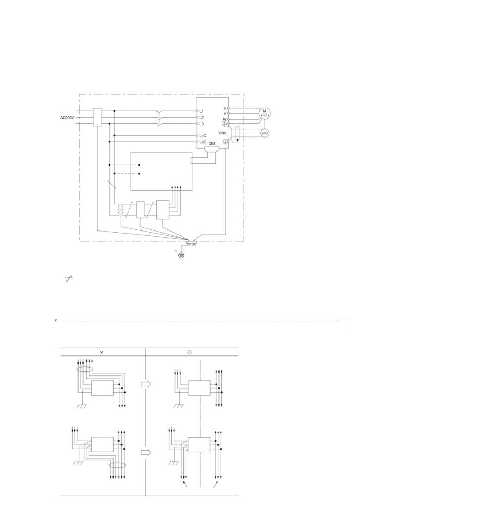
Please carry out proper grounding treatment.
Noise filter
Connect the interference filter at an appropriate place to avoid the adverse effect of interference on servo
drive.
The following is an example of wiring considering anti-interference measures.
Servo unit
Interference filter
Servo motor
Above
2.0mm2
Above
2.0mm2
Operation relay sequence
control loop
User signal generation loop
Interference filter *2
CD
power
supply
Above 2.0mm2
(Grounding plate)
Earth grounding ... must be special for grounding
*1. Please try to use a thick wire of more than 2.0 mm2 for grounding (flat braided copper wire is more suitable).
*2.
Please try to use double stranded wires for connection.
Noise Filter Wiring and Connection Precautions
Please observe the following precautions when wiring and connecting interference filters.
删除[侯]:
y Please separate the input wiring from the output wiring. In addition, do not put the input and output wires into
the same sleeve, nor bind them together.
Interference
Interference
filter
filter
Grounding plate
Grounding plate
Interference
Interference
filter
filter
Grounding plate
Grounding plate
Separate the circuit
10
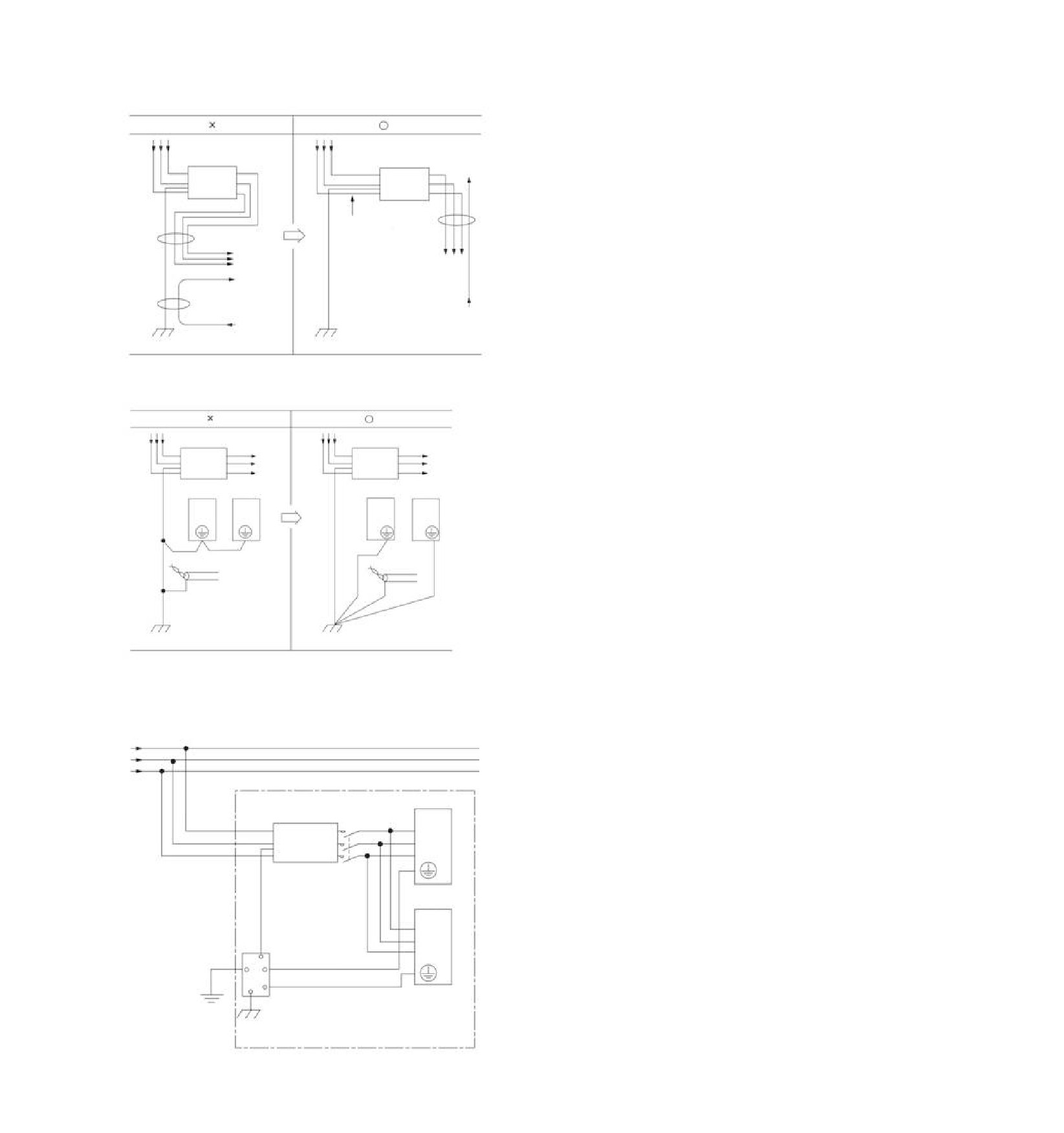
y Please set the ground wire of interference filter separately from the output wire. In addition, the ground wire
should not use the same sleeve as the output wiring of the interference filter and other signal wires, nor
should it be tied together.
Interference
Interference
filter
filter
Can be close to the
input line
Grounding plate
Grounding plate
y Connect the ground wire of the interference filter to the ground plate separately. Do not connect other ground
wires.
Interference
Interference
filter
filter
Servo unit Servo unit
Servo unit Servo unit
Shield
earthing
Grounding plate
Grounding plate
y Please connect the ground wire of this filter and the ground wire of other equipment in the control cabinet to
the ground plate of the control cabinet when there is an interference filter inside the control cabinet, and then
connect to the ground.
Control cabinet
Servo unit
Interference
filter
Servo unit
Grounding
Grounding plate
11
4.1.3
Grounding
Please follow the following for grounding treatment. If proper grounding treatment is adopted, misoperation
caused by interference can also be prevented.
When connecting the grounding cable, please pay attention to the following points:
y Please use the grounding above Class D (grounding resistance below 100Ω).
y One point must be grounded.
y When the servo motor and the machine are insulated from each other, please directly ground the servo
motor.
Grounding of motor housing or motor
The switch interference current will flow out from the servo drive main loop through the floating capacitor of the
servo motor when the servo motor is mechanically grounded. Please be sure to connect the motor housing
terminal (FG) or ground terminal (FG) of the servo motor with the ground terminal of the servo drive in order to
prevent this phenomenon. In addition, the ground terminal”
” must be grounded.
When noise occurs in cables for input and output signals
Please connect the shielded wire of the cable for input and output signals to the connector housing before
grounding when interference occurs in the cable for input and output signals. The metal sleeve and the
grounding box are grounded at a single point when the main loop cable of the servo motor is sheathed with a
metal tube.
12
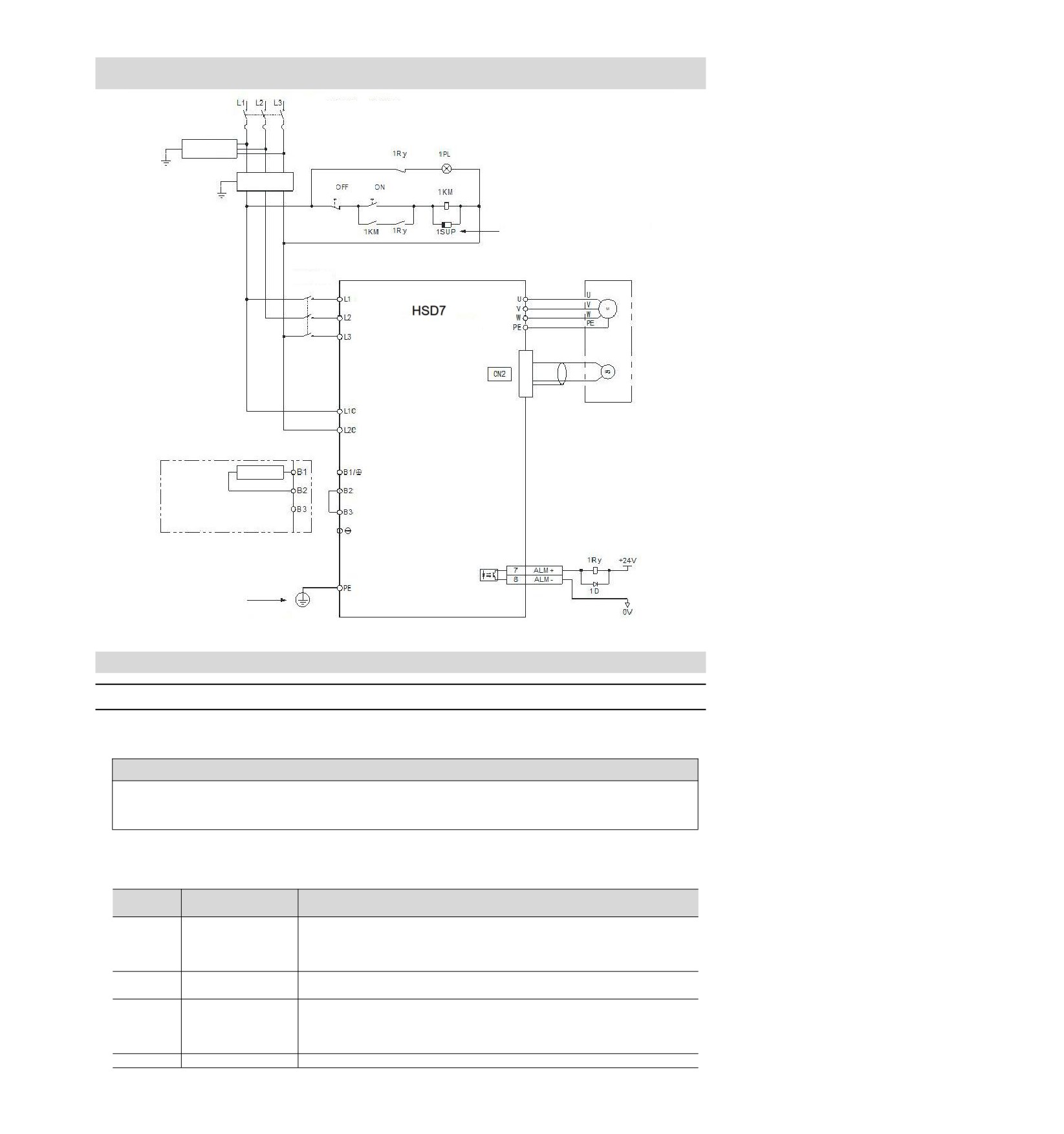
4.2 Basic connection diagram
Three-phase AC 200~230V (50/60Hz)
Non-fuse breaker
Three-phase AC 380~420V (50/60Hz)
Surge
protector
(Servo Alarm Display)
Noise filter
Power
Power
Please connect a surge arrester to the coil of the
electromagnetic contactor.
Magnetic
Servo motor
contactor
series servo driver
Encoder
Connect external regenerative
resistor
Must be grounded
4.3 Power supply wiring for servo drive
4.3.1
Terminal symbol and terminal name
The connection of servo-driven main circuit power supply and control circuit power supply uses servo-driven
main circuit connector or terminal strip.
! Warning
Please refer to the following table and the description in the reference section for correct wiring. Incorrect
wiring will lead to servo drive failure and fire.
The main loop power input specifications for servo drive are as follows:
■ Single phase/three phase AC220V power input
Terminal
Terminal name
Specifications
symbol
Main circuit power
supply input terminal
Three phase AC 200V~240V,-15%~+10%,50/60Hz
L1, L2, L3
for AC power supply
Single phase AC 200V ~ 240V,-15% ~+10%, 50/60Hz
input
Control power
Single phase AC 200V ~ 240V,-15% ~+10%, 50/60Hz
L1C, L2C
terminal
Remove the short wire or short piece between B2-B3 when the regeneration
B1/⊕、B2、
Regenerative resistor
capacity is insufficient and connect the external regeneration resistor between
B3
connection terminal
B1/⊗ and B2.
Please purchase an external regenerative resistor separately.
-
None (Do not connect it to the terminals.)
13
■ Three phase AC380V power input
Terminal
Terminal name
Specifications
symbol
Main circuit power
supply input terminal
L1, L2, L3
Three phase AC 380V~420V,-15%~+10%,50/60Hz
for AC power supply
input
Control power supply
L1C, L2C
DC 24V,-10% ~ +10%
terminal
HSD7DS-15D , HSD7DS-18D , Remove the short wire or short piece
between B2-B3 when the regeneration capacity is insufficient and connect the
external regeneration resistor between B1/⊗ and B2.
B1/⊕、B2、
Regenerative resistor
Please purchase an external regenerative resistor separately.
B3
connection terminal
HSD7DS-24D and HSD7DS-35D no built-in regenerative resistor, and
cannot be shorted between B2 and B3. External regenerative resistor shall be
connected between B1/⊗ and B2. Please purchase an external regenerative
resistor separately.
-
None (Do not connect it to the terminals.)
4.3.2
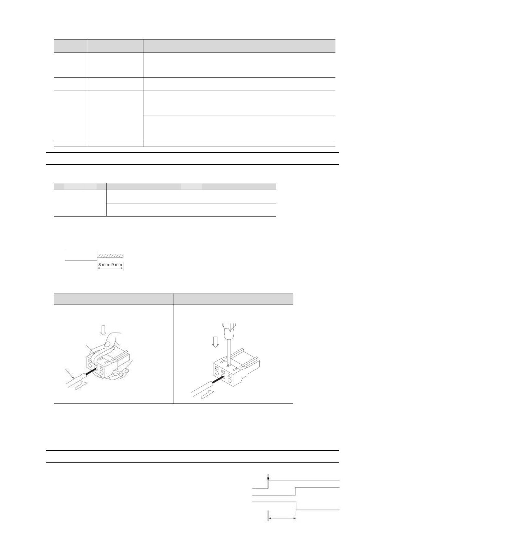
Wiring Operation Steps of Main Loop Connector
y Prepare items
Prepare items
Remarks
y Spring opener
Spring opener
Servo drive appurtenances
or
y Slotted screwdriver
Slotted screwdriver
Commercial products with cutting edge width of 3.0mm-3.5mm
1. Remove the main circuit connector and motor connector from the servo drive.
2. Peel off the cladding of the used wires.
3. Use a tool to open the wire insertion part of the terminal connector. There are two methods of opening. You
can choose any of them.
①Use method of spring opener
②Use method of flat screwdriver
The opening operation is performed using a
As shown in the figure, insert a flat-blade
spring opener as illustrated
screwdriver into the screwdriver insertion opening
to open the wire insertion part.
Spring opener
Wire
4. Insert the core wire part of the wire into the wire insertion part. After insertion, pull out the spring opener or a
slotted screwdriver.
5. Repeat the above operations and make necessary connections.
6. After wiring is completed, install the connector to the servo drive.
4.3.3
Power on sequence control
Please consider the following points when designing the
Connect to the power
power on sequence control.
After the control power is turned on, the servo alarm
Control power supply
Main circuit power
output (ALM) signal is output within a maximum of 5.0
supply
seconds. Please consider it when the power onServoAlarmOutput
(ALM) Signal Alarm status
Alarm release status
Maximum 5.0s
14
//////////////////////