HSD7-E Series AC Servo Drive. User's Manual (Version: V0.1) - page 2
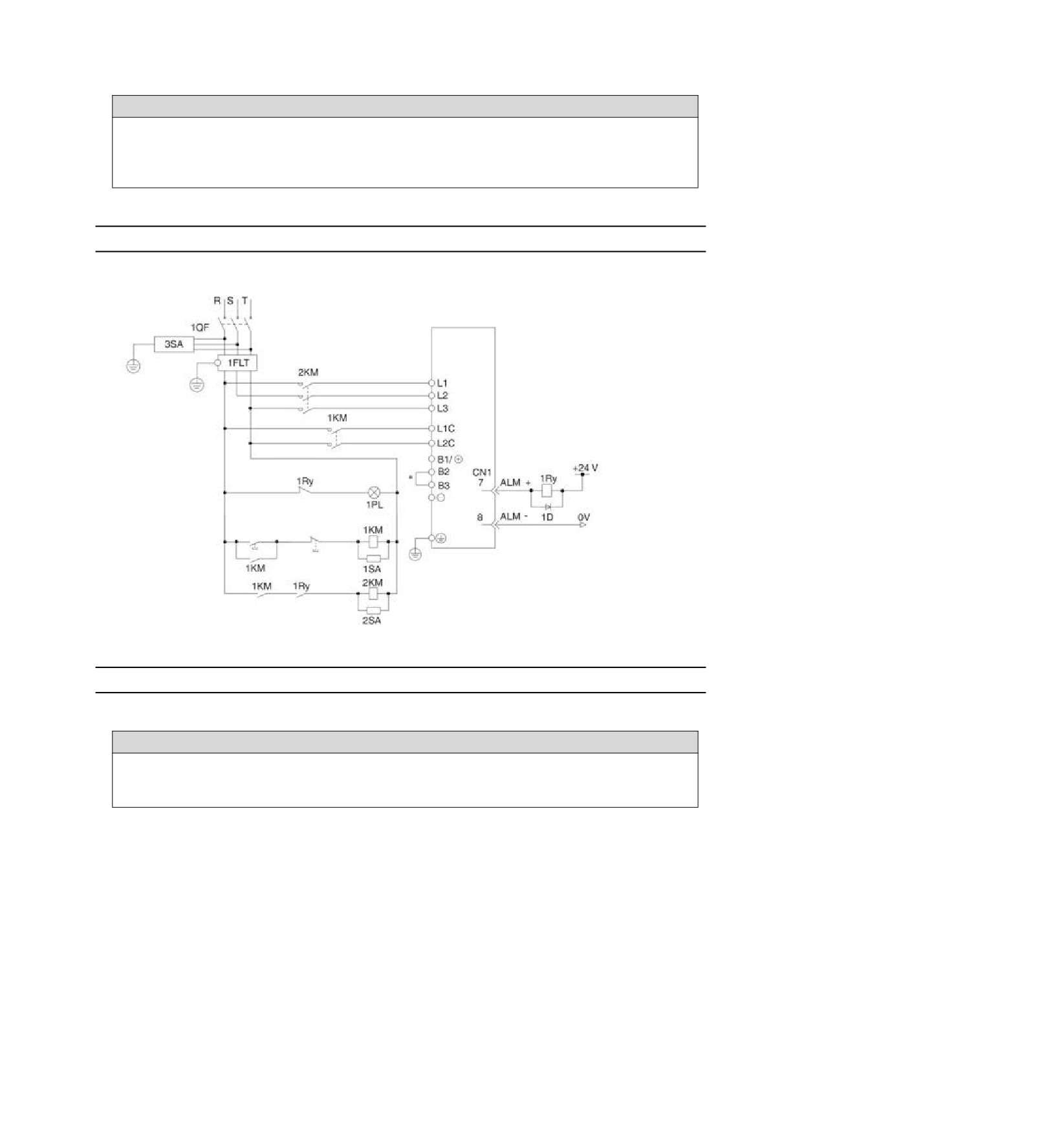
sequence control. Switch on the main circuit power
supply after ALM signal OFF (alarm cleared).
! Warning
Even if the power supply is turned off, high voltage may remain in the servo drive. To prevent electric shock, do
not touch the power terminals. After the discharge is completed, the CHARGE indicator will go out. Please
connect and check after confirming that the CHARGE indicator is off.
4.3.4
Power wiring diagram
Example of wiring for three-phase power input:
Servo unit
(For servo alarm
display)
Servo
Servo
power on
power off
1Ry: relay
1QF: circuit breaker for wiring
1PL: Indicator for Display
1FLT: noise filter
1KM: electromagnetic contactor (for
1SA: Surge Absorber
controlling power supply)
2SA: Surge absorber
2KM: electromagnetic contactor (for
3SA: Surge Absorber
main circuit power supply)
1D: Bypass Diode
* HSD7-24D, HSD7-35D No built-in resistor, no short circuit between B2 and B3. Please do not short-circuit.
4.3.5
Connection of Regenerative Resistance
The connection of the external regenerative resistor will be described below.
! Warning
Do not mistake the wiring of the regenerative resistor. In particular, do not short-circuit B1/⊕ -B2.
Otherwise, the regenerative resistor and servo drive will be damaged and fire will occur.
Connection method of regenerative resistor
1. Remove the wire between terminals B2-B3 of servo drive
2. Connect external regenerative resistor to B1/⊗ and B2 terminals.
3. Set Pn600 (regenerative resistance capacity) and Pn603 (regenerative resistance value).
(Note) HSD7-24D and HSD7-35D no built-in regenerative resistor, and cannot be shorted between B2 and B3.
External regenerative resistor shall be connected between B1/⊗ and B2.
15
4.4 Servo motor connection
4.4.1
Terminal symbol and terminal name
Servo drive terminals and connectors required for connection between servo drive and servo motor are as
follows.
Terminal/connector
Terminal/connector name
symbol
Servo motor power supply connection
U, V, W
terminal
Ground terminal
CN2
Servo motor encoder connector
4.4.2
Pin Arrangement of Connector (CN2) for Encoder
Terminal pin
Signal name
Function
number
1
PG5V
Encoder Power +5V
2
PG0V
Encoder Power 0V
3
E+*
Battery (+) for absolute value encoder
4
E-*
Battery for absolute value encoder (-)
5
SD+
Encoder serial data (+)
6
SD-
Encoder serial data (-)
Housing
Shielded
——
* Incremental encoders do not require wiring.
4.4.3
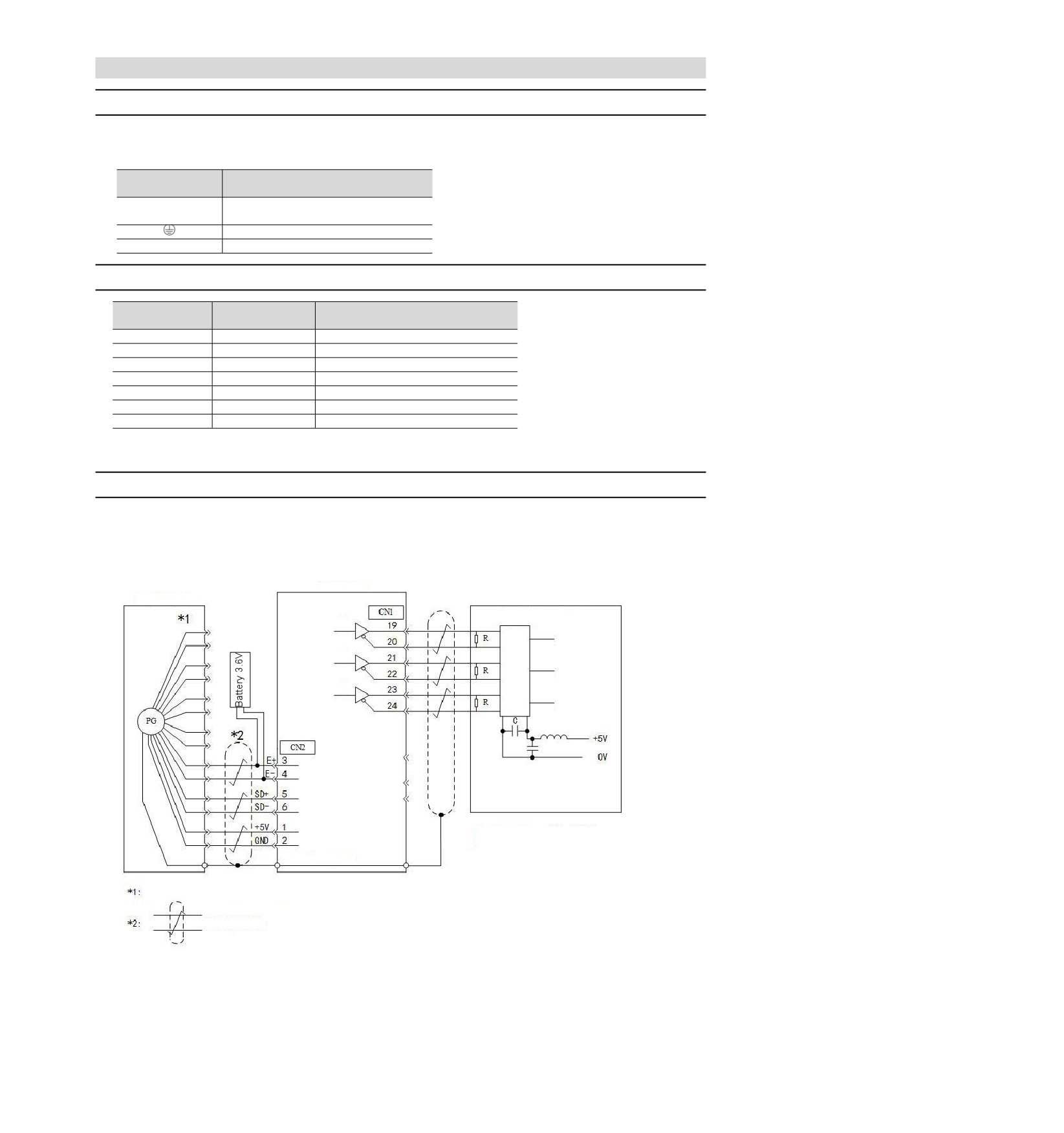
Connection of Servo Drive and Encoder
Absolute value encoder
When using absolute value encoder, please install battery on encoder cable with battery unit.
• Example of Wiring Using Encoder Cable with Battery Unit
Servo driver
Absolute position
Command Controller (Client)
Bus receiver
A Phase
A Phase
B Phase
B Phase
C Phase
C Phase
Choke
R (termination resistance): 220-470Ω
C (decoupling capacitor): 0.1μF
Connector housing (PE)
Shielded wire
The number of connector pins varies depending on the servo motor used.
Indicates a multi-stranded shielded wire.
16
4.4.4
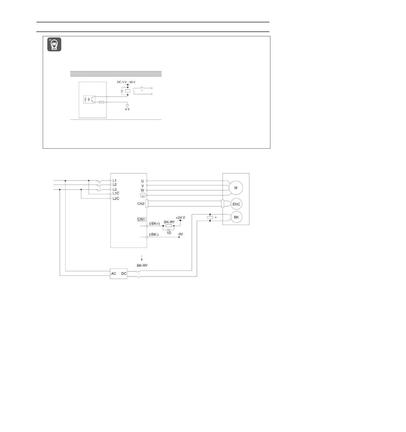
Wiring of Servo Drive and Brake
y When using a motor with a brake, please select a surge absorber according to the brake current and power
supply used.
y Please confirm the brake action time through the user equipment after connect the surge absorber.
Important
The brake action time will vary depending on the type of surge absorber.
y Please form a relay circuit to enable the brake to operate in case of emergency stop.
Example of relay circuit
Servo unit
Emergency stop
Photocoupler
y The brake control output (/BK) signal can change the distribution of the output signal.
y When using the 24V brake, the DC 24V power supply must be separated from the input and output signals
(CN1) and other power supplies separately.
Common power supply will lead to misoperation of input and output signals.
Servo motor
Servo unit
with brake
Power supply
Surge
suppressor
Direct current side
Brake power supply
BK-RY: brake control relay
1D: Bypass Diode
* Please install it near the brake terminal of servo motor.
17
4.5 Connection of input and output signals
4.5.1
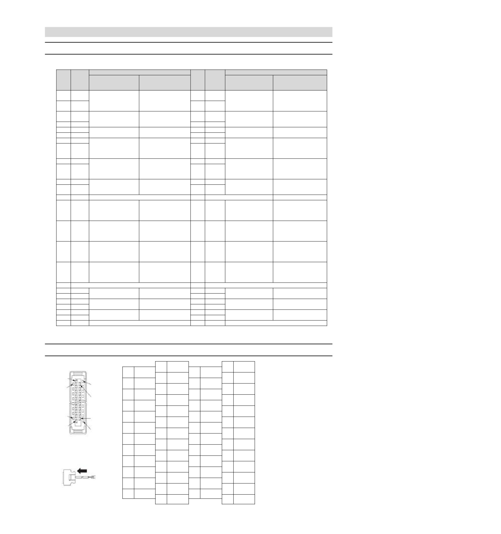
Name and function of input/output signal connector (CN1)
In factory setting, the pin number, name and function of input and output signals are as follows.
Needl
Function
Needl
Function
e
e
Name
Name
numb
Uniaxial driver
Biaxial drive
numb
Uniaxial driver
Biaxial drive
er
er
APULS
1
26
BPULS+
+
A axis command pulse
b axis command pulse
Command pulse input
Reservation
APULS
input
input
2
27
BPULS-
-
BSIGN
3
Command symbol
A axis command
28
BSIGN+
b axis command symbol
+
Reservation
input
symbol input
input
4
BSIGN-
29
BSIGN-
5
ANA1+
A axis speed command
30
ANA2+
Torque command
b axis speed command
Speed command input
6
ANA1-
input
31
ANA2-
input
input
7
OUT0+
Output outlet 0,
32
OUT3+
Output outlet 0,
Output outlet 3,
Output outlet 3,
redistributable
redistributable
redistributable
redistributable
8
OUT0-
(Ex-factory: A axis
33
OUT3-
(Factory: ALM)
(Factory Reservation)
(Ex-factory: b axis ALM)
ALM)
9
OUT1+
Output outlet 1,
34
OUT4+
Output outlet 4,
Output outlet 1,
Output outlet 4,
redistributable
redistributable
redistributable
redistributable
10
OUT1-
(Ex-factory:
35
OUT4-
(Ex-factory: b axis /
(Ex-factory:/COIN)
(Factory Reservation)
Z-axis/COIN)
COIN)
11
OUT2+
Output outlet 2,
Output outlet 2,
36
OUT5+
Output outlet 5,
Output outlet 5,
redistributable
redistributable
redistributable
redistributable
12
OUT2-
37
OUT5-
(Ex-factory:/BK)
(Ex-factory: A axis / BK)
(Factory Reservation)
(Ex-factory: b axis / BK)
13
DICOM
Input signal common terminal
38
--
Input outlet 0,
Input outlet 4,
Input outlet 0,
Input outlet 4,
redistributable
redistributable
14
IN0
redistributable
39
IN4
redistributable
(Ex-factory: A axis / S-
(Ex-factory: b axis / S-
(Ex-factory:/ S- ON)
(Factory Reservation)
ON)
ON)
Input outlet 1,
Input outlet 5,
Input outlet 1,
Input outlet 5,
redistributable
redistributable
15
IN1
redistributable
40
IN5
redistributable
(Ex-factory: A axis /P -
(Ex-factory: b axis / P-
(Ex-factory:/P- CON)
(Factory Reservation)
CON)
CON)
Input outlet 2,
Input outlet 6,
Input outlet 2,
Input outlet 6,
redistributable
redistributable
16
IN2
redistributable
41
IN6
redistributable
(Ex-factory: A axis /P -
(Ex-factory: b axis / P-
(Ex-factory:/P- OT)
(Factory Reservation)
OT)
OT)
Input outlet 3,
Input outlet 7,
Input outlet 3,
Input outlet 7,
redistributable
redistributable
17
IN3
redistributable
42
IN7
redistributable
(Ex-factory: A axis /N -
(Ex-factory: b axis /N -
(Ex-factory:/N- OT)
(Factory Reservation)
OT)
OT)
18
--
43
--
19
APAO+
PG frequency division
A Axis PG frequency
44
BPAO+
A Axis PG frequency
Reservation
20
APAO-
output phase A
division output phase A
45
BPAO-
division output phase A
21
APBO+
PG frequency division
A Axis PG frequency
46
BPBO+
b Axis frequency division
Reservation
22
APBO-
output phase B
division output phase B
47
BPBO-
output phase B
23
APCO+
PG frequency division
A Axis PG frequency
48
BPCO+
b Axis frequency division
Reservation
24
APCO-
output phase C
division output phase C
49
BPCO-
output phase C
25
GND
Signal ground
50
GND
Signal ground
(Note) 1. Do not use the vacant terminals.
2. Please connect the shielded wire of the input and output signal cable to the connector housing.
4.5.2
Pin Arrangement of Input and Output Signal Connector (CN1)
1
PULS+
26
-
2
No. 1 niddle
PULS-
27
-
3
SIGN+
28
-
No. 26 niddle
No. 2 niddle
4
SIGN-
29
-
5
VREF+
30
TREF+
No. 27 niddle
6
VREF-
31
TREF-
7
ALM+
32
OUT3+
8
ALM-
33
OUT3-
No. 24 niddle
9
OUT1+
34
OUT4+
No. 49 niddle
10
OUT1-
35
OUT4-
No. 25 niddle
11
OUT2+
36
OUT5+
No. 50 niddle
12
OUT2-
37
OUT5-
13
DICOM
38
-
14
IN0
39
IN4
The appearance when the
15
IN1
40
IN5
connector housing is not installed
as seen from the arrow direction
16
IN2
41
IN6
is as follows.
17
IN3
42
IN7
18
-
43
-
19
PAO+
44
-
20
PAO-
45
-
21
PBO+
46
-
22
PBO-
47
-
23
PCO+
48
-
24
PCO-
49
-
25
GND
50
-
18
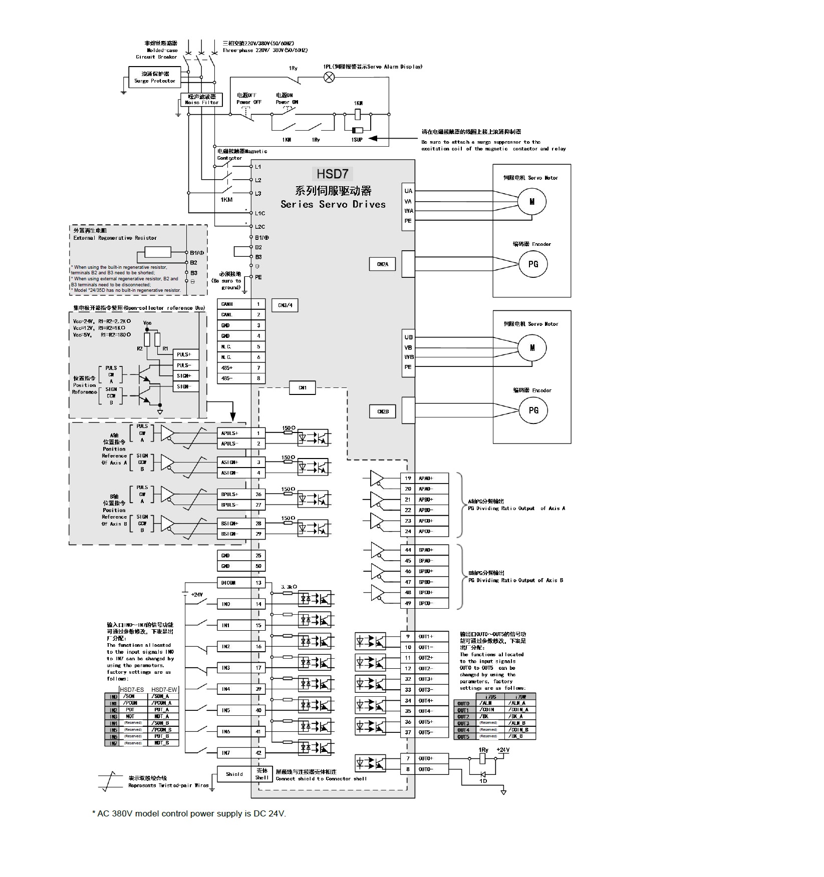
4.5.3
Examples of wiring for input and output signals
■ Position control mode
* When using the built-in regenerative resistor,
terminals B2 and B3 need to be shorted;
* When using external regenerative resistor, B2 and
B3 terminals need to be disconnected;
* Model *24/35D has no built-in regenerative resistor.
(Reserved)
(Reserved)
(Reserved)
(Reserved)
(Reserved)
(Reserved)
(Reserved)
* AC 380V model control power supply is DC 24V.
19
■ Speed/Torque Control Mode
* When using the built-in regenerative resistor,
terminals B2 and B3 need to be shorted;
* When using external regenerative resistor, B2 and
B3 terminals need to be disconnected;
* Model *24/35D has no built-in regenerative resistor.
(Reserved)
(Reserved)
(Reserved)
(Reserved)
(Reserved)
(Reserved)
(Reserved)
* AC 380V model control power supply is DC 24V.
20
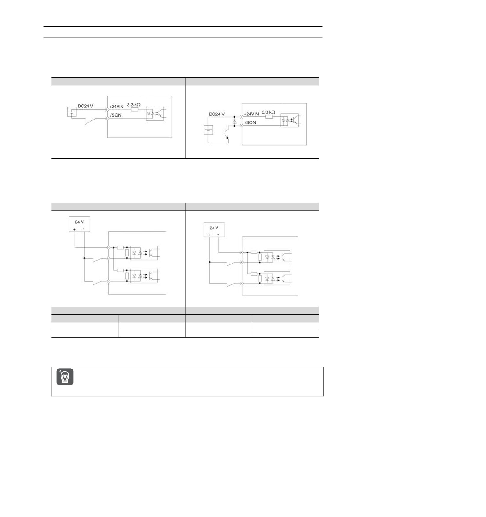
4.5.4
Input-output loop
Sequential control input loop
◆ Optocoupler Input Loop
The CN1-IN0 ~ CN1-IN7 terminals of CN1 port will be described below.
Example of relay circuit
Example of open collector Circuit
Servo unit
Servo unit
etc.
(Note) The external power supply (DC24 V) must have a capacity above 50 mA.
The servo-driven input loop uses a bidirectional optocoupler.
Please select common collector loop connection or common emitter loop connection according to mechanical
specifications.
Common collector loop
Common emitter loop
Servo unit input side
Servo unit input side
Photocoupler
Photocoupler
Internal
Internal
signal
signal
Switch
Switch
level
level
Photocoupler
Photocoupler
Internal
Internal
signal
signal
Switch
Switch
level
level
Polarity of input signal
Polarity of input signal
Photocoupler
Internal level signal
Photocoupler
Internal level signal
ON
L level
ON
L level
OFF
H level
OFF
H level
Sequential control output loop
The output circuit may be short-circuited due to wrong wiring and application of abnormal voltage.
The brake does not operate, which may lead to mechanical damage or casualties when the above-mentioned
faults occur.
Important
21
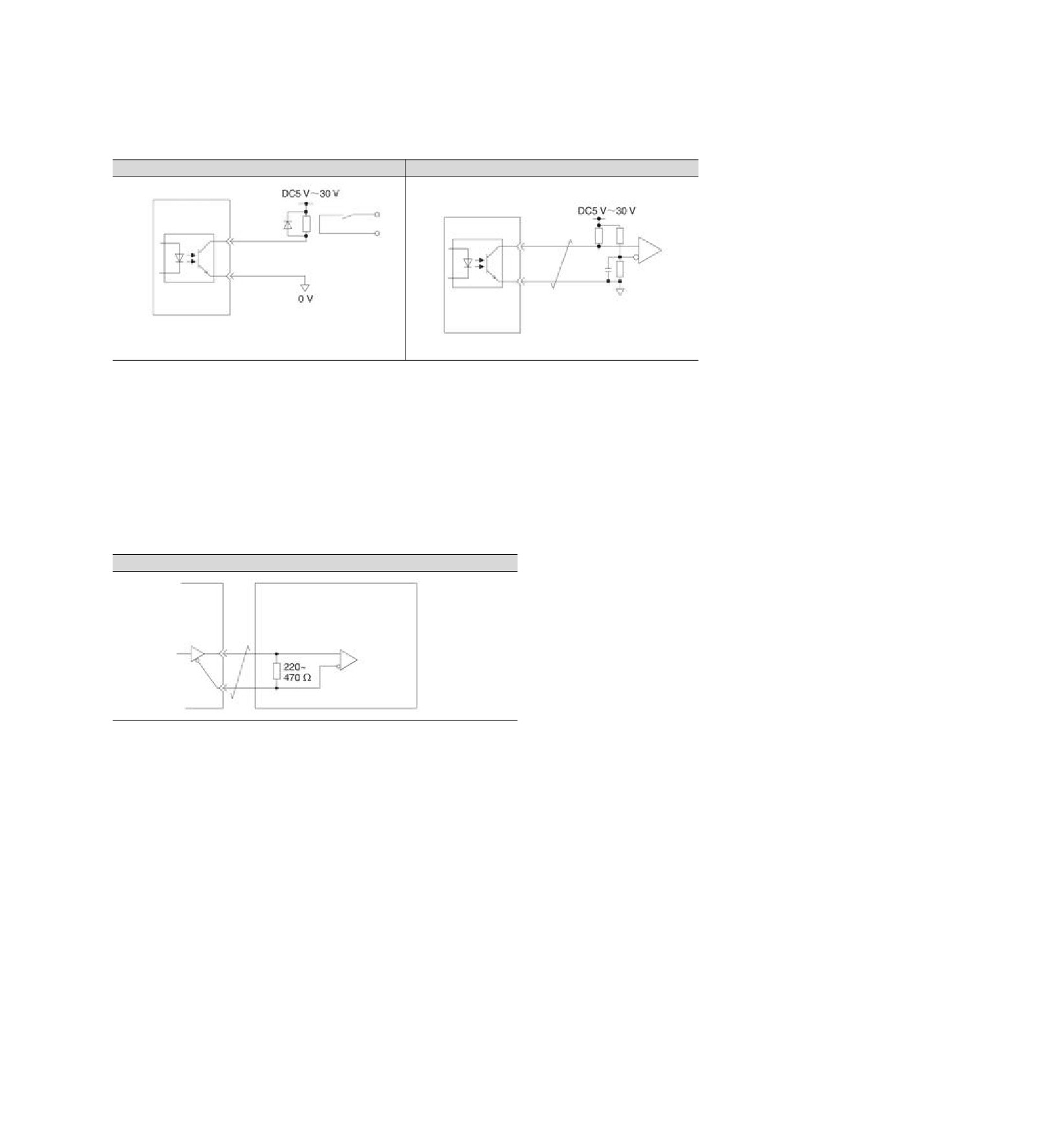
◆ Optocoupler output Loop
Servo alarm output (ALM) signal, servo ready output (/S-RDY) signal and other sequence control output
signals are optocoupler output loops. Connect via relay circuit or line receiver circuit.
Example of relay circuit
Example of open collector Circuit
Servo unit
Servo unit
Relay
(Note) The maximum allowable voltage and current ranges of the output loop of the photocoupler are as follows.
• Maximum allowable voltage: DC30 V
• Current range: DC5 ~ 50 mA
◆ Output loop of linear driver
Next, the CN1-19 ~ 24 (A, B, C phase signals) terminals of CN1 port will be described.
The serial data of the encoder is converted into output signals (PAO+, PAO-, PBO+, PBO-) of 2-phase
(A-phase, B-phase) pulses and origin signals (PCO+, PCO-) in one coil of the encoder are output through the
output loop of the linear driver. On the upper device side, please use the line receiver circuit to receive.
Example of Line Receiver Loop
Servo unit
Upper device
22
Chapter 5
Basic functions to be set before operation
5.1 Operation of Parameters (Pn)
The following describes the classification, writing method and setting method of parameters used in this
manual
5.1.1
Classification of the parameter
The servo drive parameters are divided into the following 2 categories.
Category
Meaning
Setting parameters
Basic setting parameters required for operation
Parameters for adjustment
Adjust parameters of servo performance
Supplementary
notes
When using the digital operator to display and set the adjustment parameters, the adjustment
parameters under factory setting will not be displayed.
Please set to Pn00b = n. 1 (all parameters are displayed).
Effective
Parameter
Meaning
Category
time
n.0
Only set parameters are displayed
Power
Pn00B
[Factory setting]
Setup
restart
n.1
Display all of the parameters
5.1.2
Writing Method of Parameters
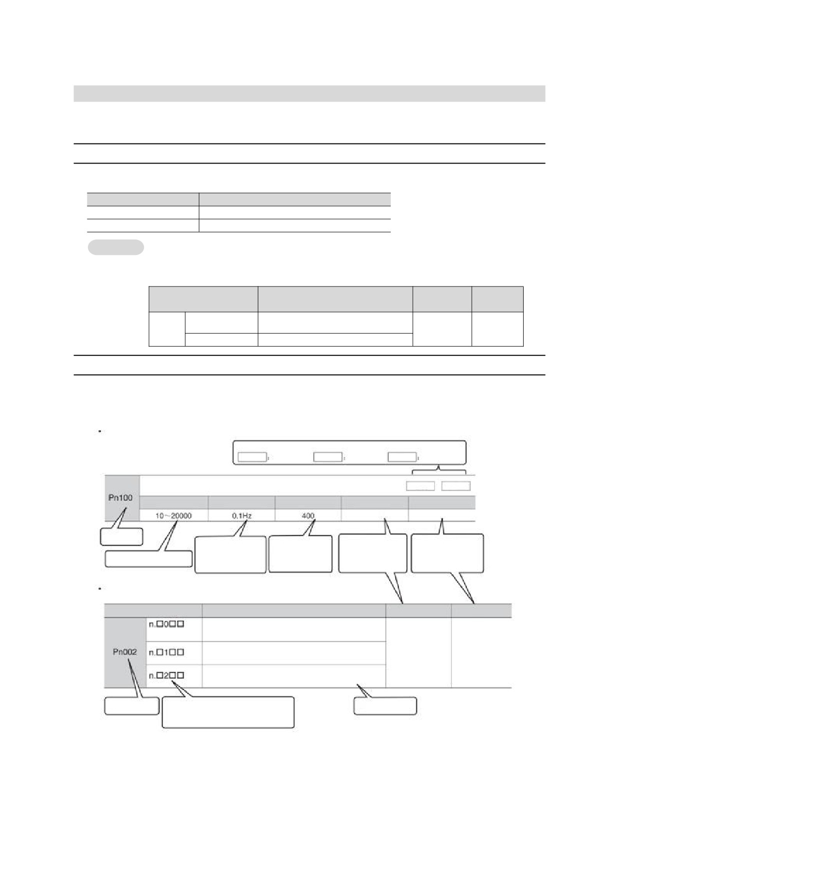
There are two writing methods for parameters: numerical setting type for setting numerical value and function
selection type for selecting function.
Numerical setting type
Indicates the control mode in which this parameter can be used.
Speed speed control
Position position control Torque
torque control
Velocity loop gain
Speed
Position
Setting range
Setting Unit
Factory setting
Effective time
Category
Effective immediately
Adjustment
Parameter
number
Indicates the "minimum"
Indicates
when the
setting unit
(scale of the
Indicates the factory
parameter changes andIndicatestheclassification
Represents a configurable
of the parameter.
setting value) that can be
parameter settings.
the change takes effect.
parameter range.
set in the parameter.
Function selection type
Parameter
Meaning
Effective time
Category
Use the encoder according to its specifications.
[Factory setting]
After switching on the
Setup
The encoder is used as an incremental encoder.
power again
The absolute value encoder is used as a 1-turn absolute value encoder.
Parameter
n. indicates that it is a function selection
Functional Selection
number
type.
Description.
The value of indicates the set value of each digit.
The third digit from the right here is "2".
23
5.1.3
How to Set Parameters
Parameters can be set using the panel operator or using iWatch+ debugging software.
5.1.4
Write inhibit setting of parameters
This function prohibits the use of panel operators to change parameters. However, iWatch+ debugging
software can be used to change parameters.
5.1.5
Initialization of parameter settings
Restore the parameters to the function used when factory setting. You can choose whether to initialize.
The values adjusted using Fn00C, Fn00D, Fn00E, Fn00F will not be initialized due to the execution of this
function.
In order for the setting to take effect, the power supply for servo drive must be switched on again after
operation.
Important
Confirmation before execution
Please confirm the following settings before initializing the parameter settings.
• The write inhibit setting of the parameter must not be set to "write inhibit"
• Must be in servo OFF state
5.2 Setting of Communication Specifications for MECHATROLINK-II
The communication specification of MECHATROLINK-II is set by servo drive parameters PA013 and PA014.
5.2.1
Communication specification setting
Effective
Parameter
Meaning
Category
time
n.0
Communication speed setting
n. 1
0: 4Mbps
[Factory setting]
1: 10Mbps
Power
Pn014
Setup
n.0
Transfer byte settings
restart
n.1
0: 17 bytes
[Factory setting]
1: 32 bytes
5.2.2
Station address setting
Address of MECHATROLINK-II station
Speed
Position
Torque
Pn013
Setting range
Setting Unit
Factory setting
Effective time
Category
0000〜00FF
--
0001
Power restart
Setup
5.3 Setting of Communication Specifications for MECHATROLINK-III
The communication specification of MECHATROLINK-III is set by servo drive parameters PA013 and PA014.
5.3.1
Communication specification setting
Effective
Parameter
Meaning
Category
time
n.0
Transfer byte settings
Power
Pn014
n.1
0: 32 bytes
Setup
restart
[Factory setting]
1: 48 bytes
24
5.3.2
Station address setting
Address of MECHATROLINK-III station
Speed
Position
Torque
Pn013
Setting range
Setting Unit
Factory setting
Effective time
Category
0000〜00FF
--
0021
Power restart
Setup
5.4 Setting of EtherCAT communication specifications
The communication specification of EtherCAT communication is set by servo drive parameters PA013 and
PA014.
5.4.1
Setting of Communication Specifications
Effective
Parameter
Meaning
Category
time
n.0
EtherCAT station address selection mode
[Factory setting]
0: set the parameter Pn013
as the station address of
Power
Pn014
EtherCAT.
Setup
restart
n.1
1: Take the value of SII area (0004h) as the station address of
EtherCAT
5.4.2
Station address setting
EtherCAT station address
Speed
Position
Torque
Pn013
Setting range
Setting Unit
Factory setting
Effective time
Category
0000〜FFFF
--
1
Power restart
Setup
5.5 Setting of Power Supply Types for Main Circuit and Control Circuit
Servo drive can also run when the main loop and control loop are AC power input or DC power input. When
selecting AC power input, the servo drive can be operated using single-phase power input or three-phase
power input. The relevant settings for the power supply are as follows.
5.5.1
Setting of AC Power Input/DC Power Input
Whether the main loop power supply for servo drive uses AC power input or DC power input is set by Pn 001 =
n.X (setting of AC/DC input for main loop power supply).
When the set value is Pn 001 = n.X, if it does not conform to the actual power input specification, A.330
(main circuit power supply wiring error) will occur.
Example of A.330 (Main Circuit Power Supply Wiring Error)
Case
When it is set to input AC power for use (Pn 001 = n. 0), DC power is input between B1/⊗ -terminals.
When the input DC power source is set to be used (Pn 001 = n. 1), AC sources are input to L1, L2 and L3
terminals.
Effective
Parameter
Meaning
Category
time
n.0
For AC power input
Power
Pn001
[Factory setting]
Setup
restart
n.1
For DC power input
! Warning
Please connect with designated terminals when AC power supply and DC power supply are connected with servo
drive.
AC power supply should be connected to L1/L2/L3 terminal and L1C/L2C terminal of servo drive.
Please connect DC power supply with B1/⊕ terminal and terminal of servo drive, L1C/L2C.
Failure to do so may result in failure or fire.
When using DC power input, be sure to set it as DC power input (Pn 001 = n.1) before inputting the main
loop power.
When DC power is input without setting it as DC power input (Pn 001 = n. 1 ), it will lead to burning of
servo-driven content components and cause fire and equipment damage.
When DC power is input, it takes a certain time to discharge after the main power is cut off. After the power supply
is cut off, high voltage will remain inside the servo drive, please pay attention to avoid electric shock.
When inputting DC power supply, please set fuse on the power supply wiring.
The servo motor returns the regenerative energy to the power supply during the regenerative action. Servo drive
does not undergo regeneration processing when using DC power input, so please conduct regeneration energy
processing on the power supply side.
25
5.5.2
Setting of Single-Phase AC Power Input/Three-Phase AC Power Input
Three-phase AC220V power supply input servo drive is of three-phase power supply input specifications, as
well as models that can be used under single-phase AC200V power supply input.
The servo drive models that can support single-phase AC220V power input are as follows.
HSD7-B(E)S-03A, HSD7-B(E)S-06A, HSD7-B(E)S-10A,
HSD7-B(E)W-03A, HSD7-B(E)W-06A, HSD7-B(E)W-10A,
When using the above servo-driven main loop power supply under single-phase AC220V power supply,
please change it to pn00b = n.1 (single-phase power input is supported).
Effective
Parameter
Meaning
Category
time
n. 0
For three-phase AC power input
Power
Pn00B
[Factory setting]
Setup
restart
n. 1
For single phase AC power input
5.6 Function and setting of servo ON input (/S-ON) signal
The servo ON input (/S-ON) signal is a signal that enables the servo motor to enter an operational state.
The function and setting of the /S-ON signal will be described below.
5.6.1
Function of servo ON input (/S-ON) signal
Signal
Type
Connector pin number
Signal status
Meaning
name
The servo motor is energized to enter a drivable
ON (closed)
state.
Output
/S-ON
Distribution required
Servo motor is not energized and cannot be
OFF (OFF)
driven.
The /S-ON signal can be set to Pn50a = n. X (servo ON input (/S-ON) signal distribution) and distributed
to terminals of other input signals.
1. Please be sure to input speed command/position command/torque command after turning on /S-ON
signal to start or stop servo motor. If a command is input first, and then the motor is started or stopped by
turning on or off the /S-ON signal and AC power supply, internal components may be aged, resulting in
motor failure.
2. Please input /S-ON signal when the servo motor is stopped. The servo cannot be turned ON when
Important
the motor rotates.
5.6.2
Set to Constant Servo ON (Motor Energized)
Pn50A = n. X (servo ON input (/S-ON) signal distribution) is set to 9 (when /S-ON signal is set to
constant servo on (motor on)), it can be set to constant servo on (motor on).
Effective
Parameter
Meaning
Category
time
n.0
[Factory
Use the /S-ON signal to turn servo ON/ servo OFF.
Power
Pn50A
setting]
Setup
restart
Set to Constant Servo ON (Motor Energized). (Fix the /S-ON
n.9
signal to always "active".)
1. If the servo ON is set to always be valid, the motor will be powered on when the power supply of the
servo drive main loop is turned on. When the speed command/position command/torque command is input,
the servo motor or mechanical system may have unexpected actions, so please take safety measures.
2. Even if an inoperable state (non-energized state) is entered due to a resettable alarm, it will
automatically return to an operable state (energized state) as long as alarm reset is performed.
Important
If the alarm reset is performed in the state of servo ON when it is set to normal, the servo motor or
mechanical system may have unexpected actions, so please pay attention.
5.7 Setting of Motor Rotation Direction
The rotation direction of the servo motor can be switched without changing the polarity of the speed
command/position command (command direction) (Pn 000 = n.X).
At this time, although the rotation direction of the motor will change, the polarity (phase relationship between
phase A and phase B) of output signals such as encoder frequency division pulse output will not change.
Please set according to the system.
26
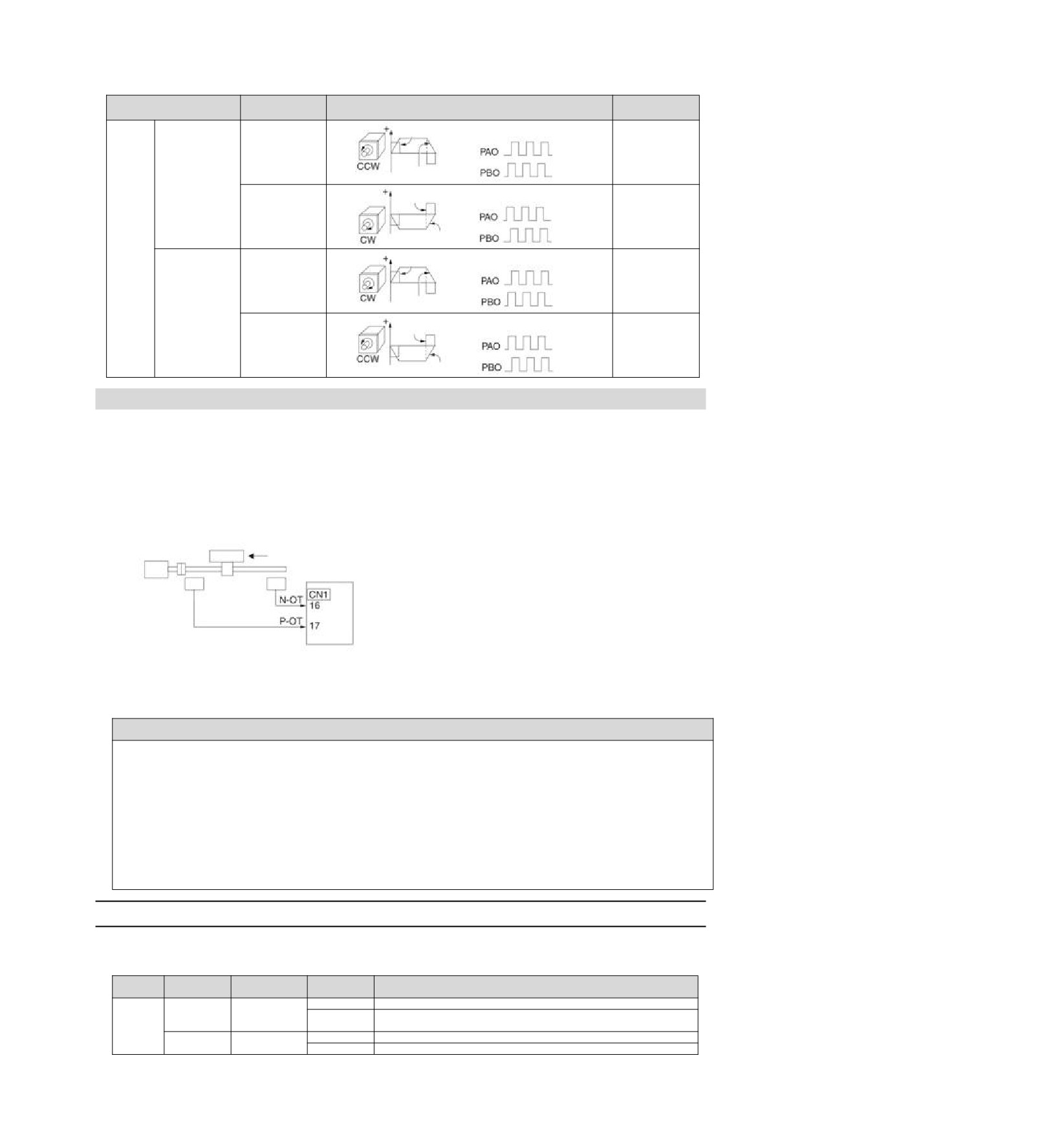
The "forward rotation direction" set by the factory is "counterclockwise rotation (CCW)" as viewed from the
load side of the servo motor.
Forward/rever
Motor rotation direction and encoder frequency division
Effective
Parameter
se command
pulse output
overtravel (OT)
Encoder frequency division
Prohibit
Torque command
pulse output
positive
n. 0 the
Forward
Time
rotation side
CCW direction
command
drive input
is the forward
Motor speed
Phase B lead
(P-OT) signal
rotation
Encoder frequency division
direction.
Torque command
pulse output
Disable
Factory
Reverse
reverse side
setting]
Time
Phase A lead
command
drive input
(N-OT) signal
Motor speed
Pn000
Encoder frequency division
Torque command
Prohibit
pulse output
positive
n. 1 the
Forward
Time
rotation side
CW direction
instruction
drive input
is the forward
Motor speed
Phase B lead
(P-OT) signal
rotation
Encoder frequency division
direction.
Torque command
pulse output
Disable
Reverse
Reverse
reverse side
Time
Phase A lead
Mode)
command
drive input
(N-OT) signal
Motor speed
5.8 Functions and settings of over-travel prevention
The over-travel prevention function of servo drive refers to the safety function of forcing the servo motor to
stop by inputting the signal of limit switch when the movable part of the machine exceeds the designed safe
movement range.
The overtravel signal includes a P-OT signal that prohibits forward rotation and an N-OT signal that prohibits
reverse rotation. The P-OT and N-OT signals are used to set a limit switch at the position to be limited when
starting the machine under the drive of the servo motor, and then stop the machine through the signals.
Examples of servo drive wiring are shown below.
Motor forward rotation direction
Servo unit
Servo
motor
Limit
Limit
switch
switch
Rotary applications such as round tables and conveyors do not require over-travel prevention function, and
there is no need to wire the over-travel prevention input signal at this time. The following is a description of the
parameter setting related to the over-travel prevention function.
! Notes
In order to prevent accidents caused by poor contact and disconnection of contact parts, please use "normally closed
contact" for limit switches.
In addition, do not change the factory setting of the polarity of over-travel signals (P-OT, N-OT).
When the servo motor is used as a vertical shaft, the brake control output (/BK) signal will remain in the ON (brake
on) state in the overtravel state, so the workpiece may fall off when overtravel occurs. In order to prevent the
workpiece from falling off, please set it to a zero fixed state after the servo motor stops (Pn 001 = n.1).
In case of overtravel, it will enter the base blocking state after stopping, but it may be dragged back when the load
shaft side receives external force. In order to prevent the servo motor from being dragged back due to external force,
please set it to a fixed zero position after the servo motor stops (Pn 001 = n.1).
5.8.1
Overtravel signal
The overtravel signal includes a P-OT signal that prohibits forward rotation and an N-OT signal that prohibits
reverse rotation.
Signal
Connector
Signal
Type
Meaning
name
pin number
status
ON
Forward-turning side can be driven (normal operation)
P-OT
CN1-IN2
It is forbidden to drive the forward rotation side (forward rotation
OFF
Input
side over travel)
ON
The reverse side can be driven (normally operated)
N-0T
CN1-IN3
OFF
Reverse side drive is prohibited (reverse side overtravel)
27
Even in the over-travel state, it is still allowed to drive in the opposite direction by inputting command.
5.8.2
Select whether the over-travel prevention function is valid/invalid
The valid/invalid over-travel prevention function can be selected by PN50A = n.X
(prohibiting the
distribution of the forward-rotation-side drive input (P-OT) signal) and PN50B = n. X (prohibiting the
distribution of the reverse-rotation-side drive input (N-OT) signal).
When the selection is invalid, there is no need to connect the input signal for over-travel prevention.
Effective
Parameter
Meaning
Category
time
n. 2
After the overtravel function takes effect, input the No Forward
[Factory setting]
Drive Input (P-OT) signal from CN1-IN2.
Power
Pn50A
Setup
Overtravel function fails. Forward rotation side drive is always
restart
n. 8
allowed.
n 3
After the overtravel function takes effect, input the drive input
Power
Pn50B
[Factory setting]
(N-OT) signal from CN1-IN3 on the reverse side.
Setup
restart
n. 8
Overtravel function fails. Reverse side drive is always allowed.
5.8.3
Selection of Motor Stopping Method for Over-travel Prevention Function
The servo mOTor stop method when the overtravel prevention function operates is selected by Pn001 = n
XX (stop method when servo OFF and Gr.1 alarm occurs, stop method when overtravel (ot)).
Effective
Parameter
Stop method of motor *
Turn state after motor stops
Category
time
n.00
[Factory setting]
Dynamic brake
Free-running operation
n. 01
n. 02
Free-running operation
Power
Pn001
Setup
n. 1
Decelerate according to
Zero position fixing
restart
n. 2
Pn406 setting
Free-running operation
n. 3
Decelerate according to
Zero position fixing
n. 4
Pn30A setting
Free-running operation
* Torque control cannot slow down to stop. According to the setting of Pn001 = n. X (servo OFF and stop method in
case of Gr.1 alarm), the dynamic brake stops or the free running stops, and enters the free running state after the servo
motor stops.
When the emergency stop torque is set to stop the servo motor
When the emergency stop torque is set to stop the servo motor, Pn406 (Emergency Stop Torque) is set.
When Pn001 = n.X is set to 1 or 2, the servo motor will be decelerated with the set torque of Pn406 as
the maximum value.
The factory setting is "800%". This is a large enough value to ensure that the servo motor must output
maximum torque. However, the actual effective maximum limit of emergency stop torque is the maximum
torque of the servo motor.
Emergency stop torque
Speed
Position
Torque
Setting range
Setting Unit
Factory setting
Effective time
Category
Pn406
Effective
0〜 800
1% *
800
Setup
immediately
* Percentage relative to rated torque of motor.
When the deceleration time is set to stop the servo motor
When setting the deceleration time of the servo motor to stop the servo motor, Pn30A (deceleration time at
servo OFF and forced stop) is set.
Deceleration Time for Servo OFF and Forced Stop
Speed
Position
Torque
Setting range
Setting Unit
Factory setting
Effective time
Category
Pn30A
Effective
0〜 10000
1ms
0
Setup
immediately
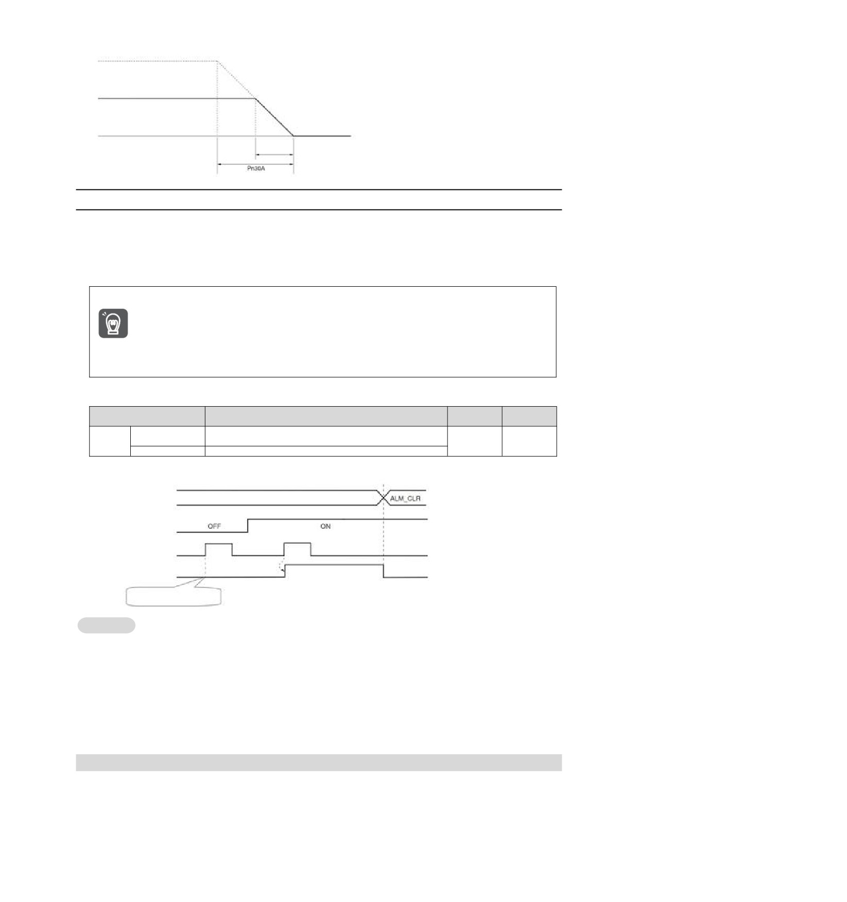
When Pn30A is set to "0", zero speed stops.
The deceleration time set by Pn30A is the time from the highest speed of the motor to the stop of the motor.
28
Maximum speed
Actual deceleration time =Actionspeed
Maximum speed
x Deceleration Time (Pn30A)
Action speed
Actual
deceleration
time
5.8.4
Overtravel warning function
The over-travel warning function refers to the function of detecting A.9A0 (over-travel warning) when entering
the over-travel state during servo ON. When using this function, even if the over-travel signal is input
instantaneously, the servo drive can notify the upper device of the occurrence of a warning. This function is
only valid when the servo is ON. When the servo is OFF, even if it enters the overtravel state, the overtravel
warning will not be detected.
y Even if A.9A0 occurs, the motor stop and the motion control action of the upper device will not be affected.
In case of over-travel warning, the next step (motion control and other commands) can still be executed.
However, according to the processing specifications and procedures of the upper-level device for warning,
the actions in case of over-travel warning may change (motion control stops or motion control does not
stop, etc.). Please confirm the specifications and procedures of the upper device.
y In case of overtravel, the servo drive will stop the overtravel, so when A.9A0 occurs, the servo motor has
Important
not reached the target position set by the upper device. Please confirm whether the shaft is stopped in a
safe position through feedback position.
This function is set by the following parameters.
Effective
Parameter
Meaning
Category
time
n.0
No over-travel warning is detected.
Power
Pn00D
[Factory setting]
Setup
restart
n.1
Check out over-travel warning.
The timing chart for detecting warnings is as follows.
Command
Motion instructions, etc
Command
Servo ON state
Over-travel signal
Invalid Effective
Invalid
Effective
Invalid
(P-OT, N-OT signal)
Overtravel Warning
Normal status
Normal status
Alarm status
(A.9A0)
Warning is not detected due to
servo OFF state.
Supplementary
1. Warnings will be detected for overtravels in the same direction as the command.
notes
2. Warning cannot be detected for overtravel in the direction opposite to the command direction.
For example, even if the N-OT signal is ON, a warning will not be issued during the movement under the
command of the positive direction.
3. In the absence of commands, warnings will be detected for overtravels in either the positive direction or
the reverse direction.
4. In the over-travel state, no warning will be detected when changing from the servo OFF state to the servo
ON state.
5. The release of the warning has nothing to do with servo ON/servo OFF and overtravel signal status. Use
the ALM_CLR command to release the warning.
6. In the over-travel state, when the warning is released by using the ALM_CLR command, the warning will
not be checked out until the over-travel state is released.
7. If soft limit is detected, over-travel warning will still be detected.
5.9 Brake
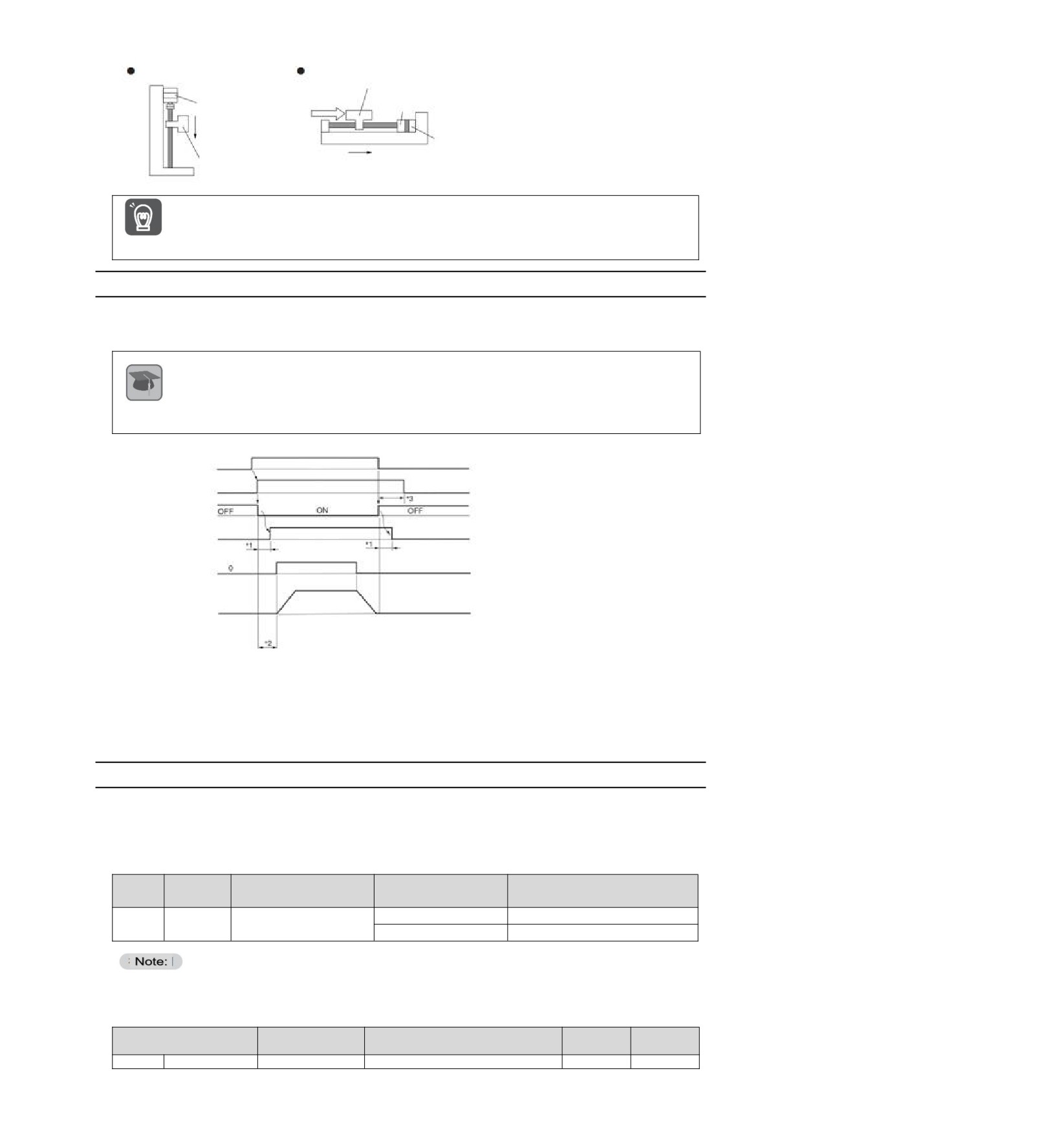
The brake is a component that maintains a fixed position when the servo-driven power supply is OFF so that
the movable part of the machine will not move due to self-weight or external force. The brake is built into the
servo motor with brake, please set it on the mechanical side.
Please use it in the situation shown below.
29
Vertical axis
Axis subject to external
Servo motor
The moving part of a
External
machine
Brake
force
Servo motor
Prevent power supply
from falling due to dead
weight when OFF
Brake
The moving part of a
The movable part of the machine is
machine
prevented from moving due to external force
The brake built in the servo motor is a fixed special brake with no excitation action and cannot be used for
braking purposes. Please only use it when the servo motor is stopped.
Important
5.9.1
Action sequence of brake
Considering the opening time and operating time of the brake, please set the operating time of the brake as
follows.
Brake opening time
The time between when the brake cONtrol output (/BK) signal is turned on and when the brake is actually
turned on.
Terminology
Brake action time
explanation
The time from when the brake control output (/BK) signal is turned OFF to when the brake actually operates.
Servo OFF
Servo OFF
Servo ON (SV_ON)
Servo NO
command
Non-
Electrical machine
energized
Energized
Non-energized
energized state
Brake Control Output
(/BK) Signal
Brake action
Brake on
Brake action
Brake contact (bushing)
Position and speed
command
Motor speed
*1. The brake action of servo motor with brake will have a delay time, which is determined by the electrical characteristics of the
brake.
*2. After SV_ON command is sent, please wait for the brake to be on for more than +50ms before outputting the commands of the
upper device to servo drive.
*3. Please use the following parameters to set the brake action and servo OFF time.
Pn506 (brake command-servo OFF delay time), Pn507 (brake command output speed value), Pn508 (servo OFF- brake
command wait time)
5.9.2
Brake Control Output (/BK) Signal
Control the output signal of the brake. The connector pin number of the allocation target can be changed.
Please refer to "Distribution of Brake Control Output (/BK) Signal" for details. When the servo is OFF or
an alarm is detected, the /BK signal is OFF (brake action). The time when the brake is operated (the time
when the /BK signal is turned OFF) is adjusted by the servo OFF delay time (Pn506).
Signal
Type
Connector pin number
Signal status
Meaning
name
ON (closed)
Release the brake
Output
/BK
Distribution required
OFF (OFF)
Make the brake action
The /BK signal remains ON in the overtravel state. At this time, the brake is released.
Distribution of brake control output (/BK) signal
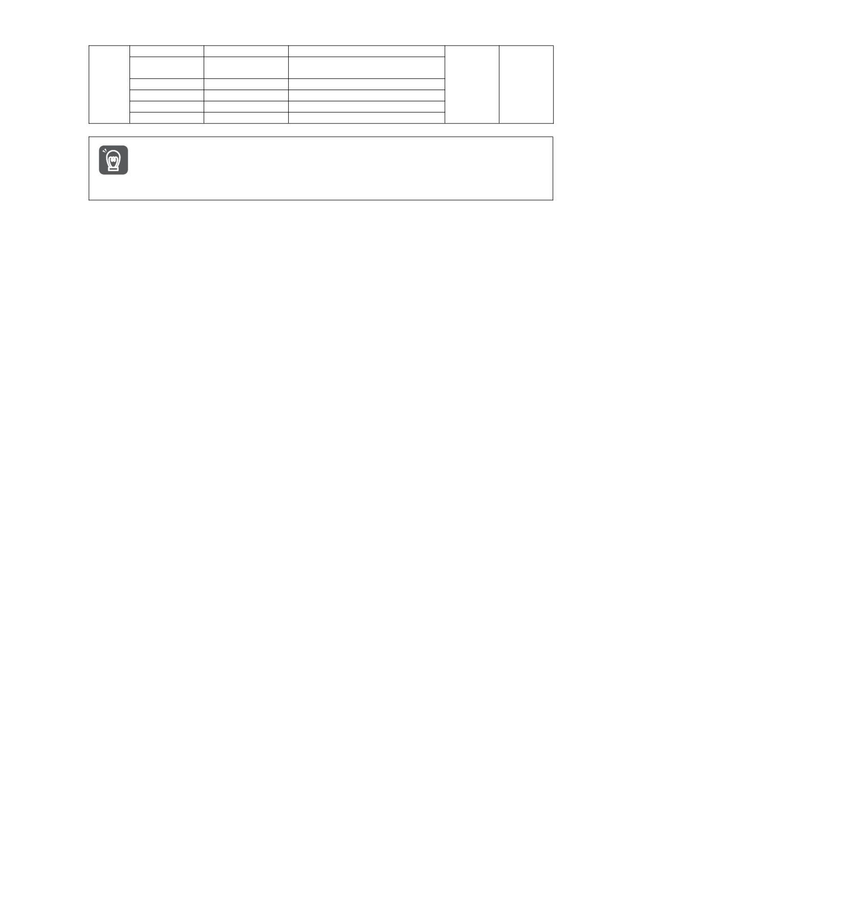
Distribution of /BK signal is set by PN50F = n.X (distribution of brake control output (/BK) signal).
Connector pin
Effective
Parameter
Meaning
Category
number
time
Pn50F
n.0
CN1-7,8
Output /BK signal from CN1-OUT0
Power
Setup
30
n.1
CN1-9,10
Output /BK signal from CN1-OUT1
restart
n.2
CN1-11,12
Output /BK signal from CN1-OUT2
[Factory setting]
n.3
CN1-32,33
Output /BK signal from CN1-OUT3
n.4
CN1-34,35
Output /BK signal from CN1-OUT4
n.5
CN1-36,37
Output /BK signal from CN1-OUT5
n.6
---
Don't use /BK signal
When multiple signals are distributed to the same output terminal, OR logic is used for signal output. Please
avoid duplication with other signals when distributing /BK signals.
In particular, please avoid distributing the rotation detection output (/TGON) signal and /BK signal to the
same output terminal. If it is distributed to the same terminal, the /TGON signal will be turned ON at the
Important
speed of falling down on the vertical axis, which may cause the brake not to operate.
31
5.9.3
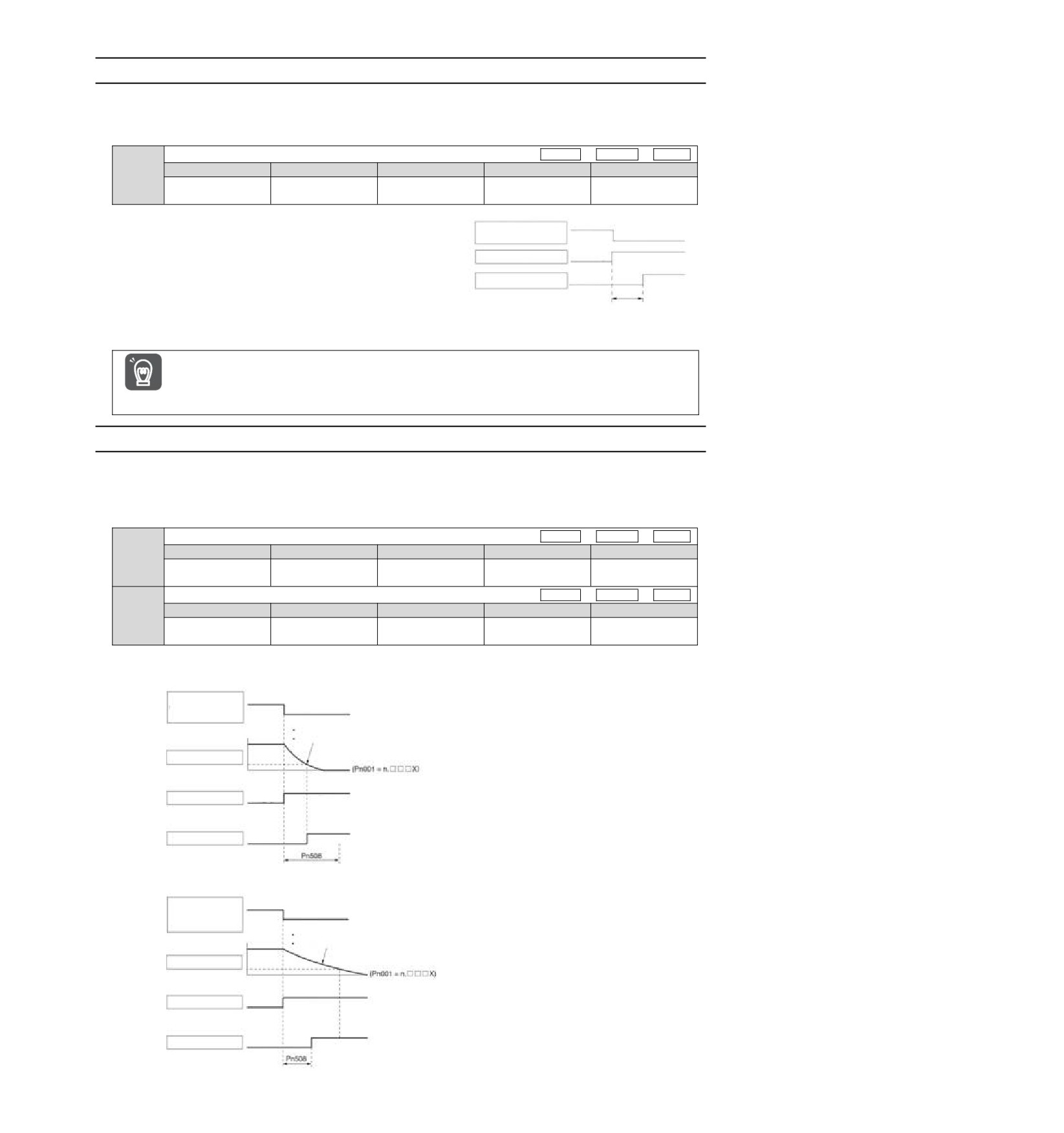
Output Time of Brake Control Output (/BK) Signal when Servo Motor Stopped
When the servo motor is stopped, the /BK signal will also be OFF when the servo OFF (SV_OFF) command is
input. By setting the servo OFF delay time (Pn506), the time when the SV_OFF command is input to the actual
motor is not energized can be changed.
Brake Command-Servo OFF Delay Time
Speed
Position
Torque
Setting range
Setting Unit
Factory setting
Effective time
Category
Pn506
Effective
0〜 10000
1ms
0
Setup
immediately
When used for vertical shafts and the like, the dead
Servo OFF (SV_OFF)
Servo ON
Servo OFF
weight or external force of the mechanical moving
command input
ON (brake
part may cause the machine to move slightly. By
/BK signal
released)
OFF (brake action)
setting the servo OFF delay time (Pn506), the motor
The motor is
can be in an energized state after the brake is
Electrical machine
energized
The motor is
energized state
not energized
activated. To eliminate slight movement of the
machine.
This parameter is used to set the time when the servo
motor is not energized when it is stopped.
When an alarm occurs, regardless of this setting, the servo motor immediately enters a non-energized state.
At this time, the machine sometimes moves before the brake is activated due to the
dead weight or external force of the movable part of the machine.
Important
5.9.4
Output Time of Brake Control Output (/BK) Signal in Servo Motor Rotation
When an alarm occurs during the rotation of the servo motor, the servo motor stops and the /BK signal is OFF.
At this time, the output time of the /BK signal can be adjusted by setting the brake command output speed
value (Pn507) and the servo OFF-brake command waiting time (Pn508).
(Note) When the stop method for alarm occurs is zero speed stop, the setting of Pn506 (brake command-servo OFF delay time)
shall be followed after the motor stops.
Brake command output speed value
Speed
Position
Torque
Setting range
Setting Unit
Factory setting
Effective time
Category
Pn507
Effective
0〜10000
1min-1
100
Setup
immediately
Servo OFF- Brake Command Wait Time
Speed
Position
Torque
Setting range
Setting Unit
Factory setting
Effective time
Category
Pn508
Effective
10〜100
10ms
50
Setup
immediately
When any of the following conditions is met, the brake will act.
When the motor speed is less than the set value of Pn507 after the motor is not energized
Servo OFF
(SV_OFF) command
input or alarm power
Servo ON
Servo OFF
OFF
Rotating servo motor: Pn507
Linear servo motor: Pn583
Motor speed
DB stop or free running stop
Electrical machine
Energized
energized state
Not energized
ON (brake
/BK signal
released)
OFF (brake action)
When the set time of Pn508 elapses after the motor enters the non-energized state
Servo OFF
(SV_OFF) command
input or alarm power
Servo ON Servo OFF
OFF
Rotating servo motor: Pn507
Linear servo motor: Pn583
Motor speed
DB stop or free running stop
Electrical machine
Energized
Not energized
energized state
ON (brake
/BK signal
released)
OFF (brake action)
32
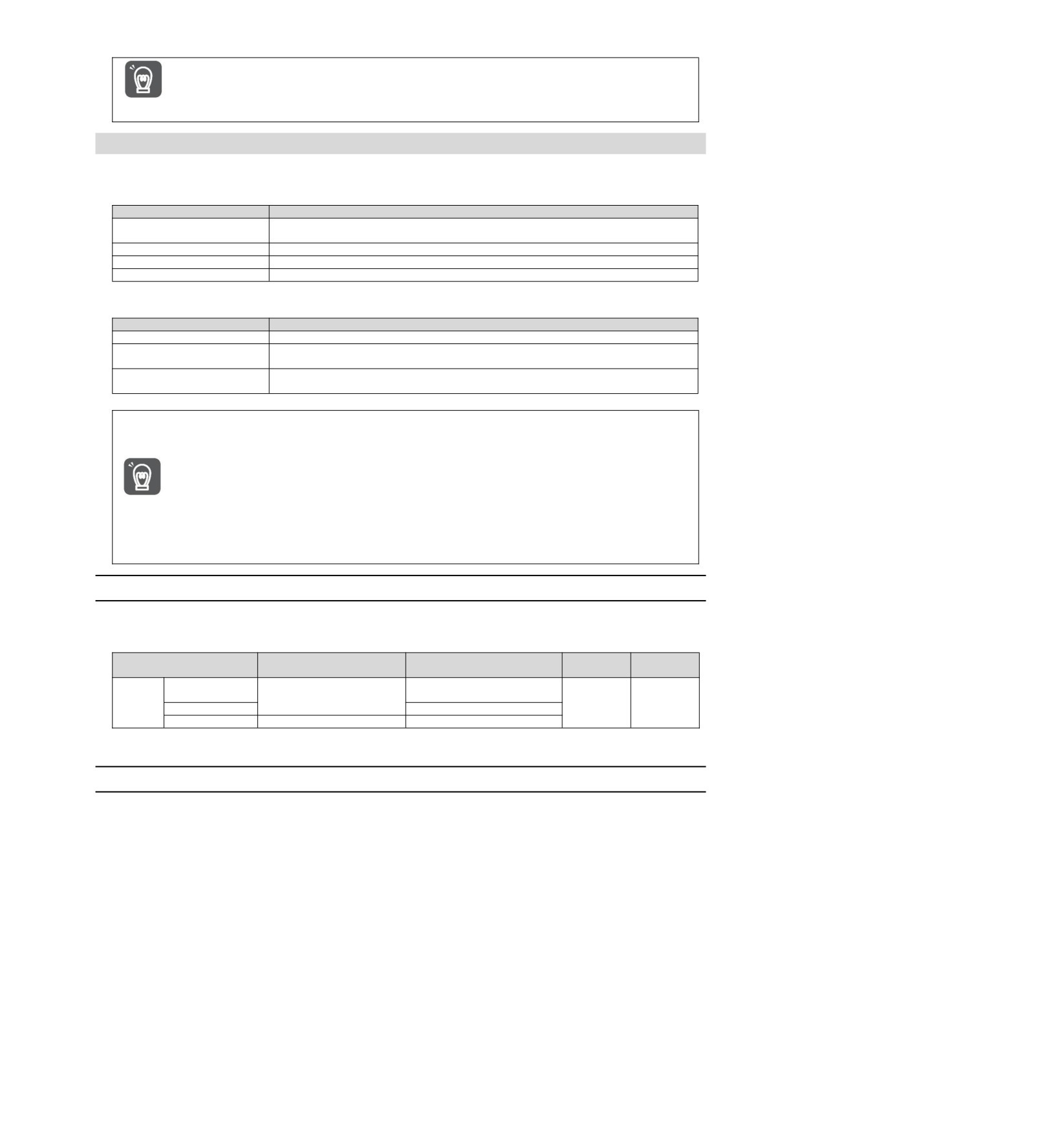
Even if the brake command output speed value (Pn507) is set to a value greater than the maximum speed of
the servo motor used, it will still be limited to the maximum speed of the servo motor.
Important
5.10 Servo OFF and Motor Stop Method in Alarm
Servo OFF and motor stop method when alarm occurs are as follows.
There are four ways to stop the motor.
Stop method of motor
Meaning
The dynamic brake (DB)
By short-circuiting the electrical circuit of the servo motor, the servo motor can be
stops
stopped urgently.
Free running stop
It stops naturally due to friction when the motor rotates.
Zero speed stop
Set the speed command to "0" to make the servo motor stop urgently.
Slow down and stop
According to the emergency stop torque deceleration stop.
There are three states after the motor stops.
Turn state after motor stops
Meaning
Turn state after motor stops
The state in which the servo motor stops after short-circuiting the electrical circuit.
The state in which the servo drive does not control the servo motor (the machine will act
Free running state
when applying force from the load side)
A position ring is formed, and the position command is a stop state of "0" (the current
Zero position fixed state
stop position is maintained)
y Dynamic brake (DB) is a function of emergency stop. If starting and stopping are performed by power
supply ON/OFF or servo ON in the state where the command is input, the DB loop will operate frequently,
resulting in aging of internal components of servo drive. Please start and stop the servo motor by speed
input command or position command.
y During operation, when the servo is not OFF and the main circuit power supply is OFF or the control power
supply is OFF, DB stop is not adopted, but when free operation stop must be adopted, please use the
servo drive applicable to the dynamic brake option.
Important
y Regarding the stopping method during alarm, in order to try to shorten the inertial moving distance when
the alarm occurs, the factory settings are all zero-speed stop for alarms that allow the selection of
zero-speed stop. However, depending on the application, sometimes DB stop is more suitable than zero
speed stop.
5.10.1 Motor Stop Method when Servo OFF
The motor stop method for servo OFF is selected through Pn 001 = n.X (servo OFF and stop method for
Gr.1 alarm).
State after the servo motor
Effective
Parameter
Stop method Servo motor
Category
stops
time
n.0
Dynamic brake
[Factory setting]
Dynamic brake
Power
Pn001
Setup
n. 1
Free-running operation
restart
n. 2
Free-running operation
Free-running operation
(Note) When Pn 001 = n.0 is set (the motor is stopped by the dynamic brake), when the servo motor stops or rotates at an
extremely low speed, no braking force will be generated as in the free running state.
5.10.2 Motor stopping method when alarm occurs
Alarms are divided into Gr.1 alarm and Gr.2 alarm. Parameters for setting the motor stop method when an
alarm occurs vary depending on the alarm type.
Motor Stop Method in Case of Gr.1 Alarm
When Gr.1 alarm occurs, the servo motor stops according to Pn 001 = n.X. Factory set to dynamic brake
stop.
Motor Stop Method in Case of Gr.2 Alarm
When Gr.2 alarm occurs, the servo motor stops according to the settings of the following 3 parameter
combinations. Factory set for zero speed stop.
• Pn001=n.X(Servo OFF and stop method when Gr.1 alarm occurs)
• Pn00A= n.X (stop method in case of Gr.2 alarm)
• Pn00B= n.X (stop method in case of Gr.2 alarm)
However, in torque control, Gr.1 stopping method is generally used. When set to Pn00B = n.1 (db stop
or free running stop), the same stop method as Gr.1 can be adopted. When using multiple servo motors in
coordination, this stopping method can be used to prevent the machine from being damaged due to different
stopping methods during alarm.
33
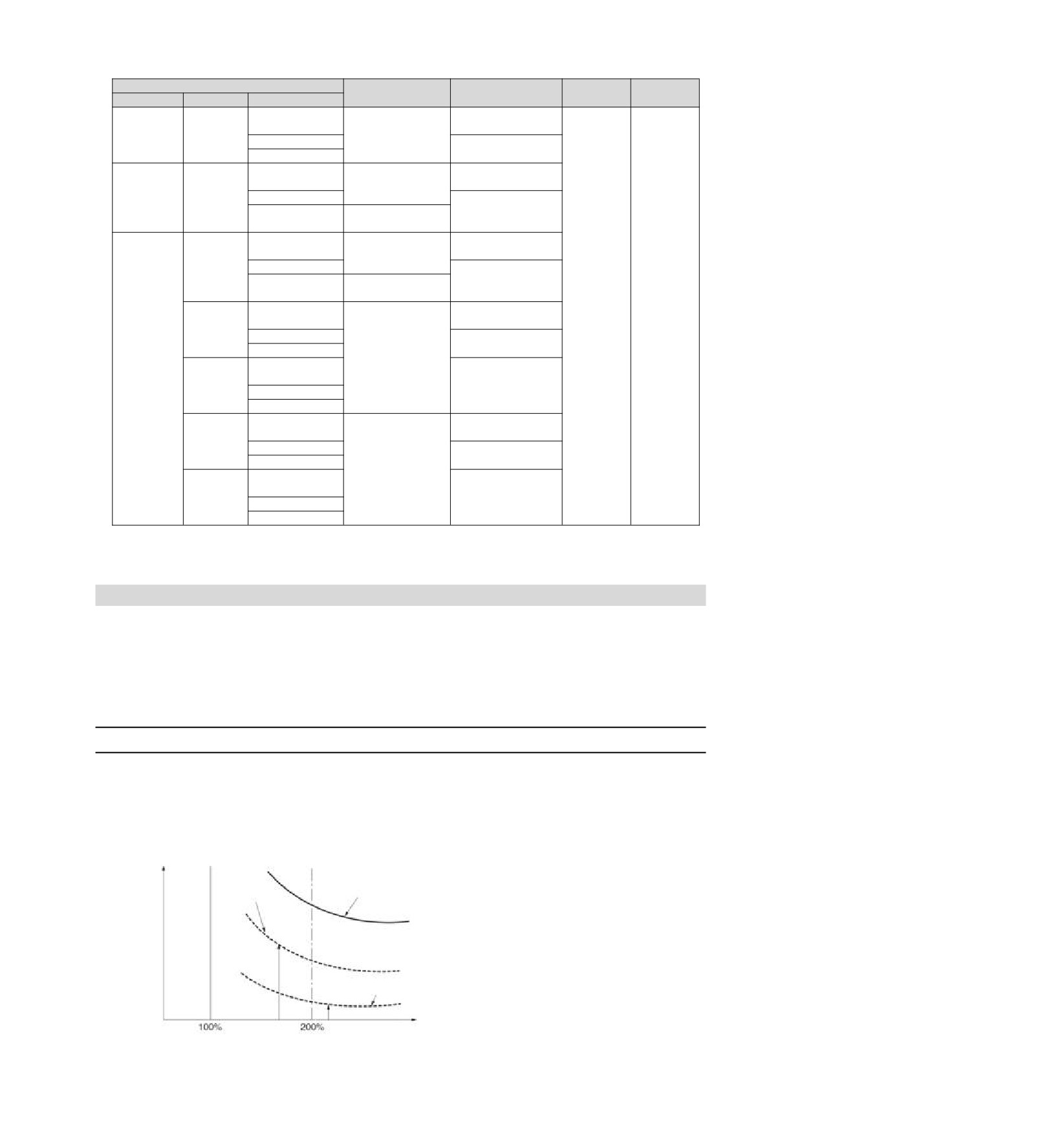
The combination and stopping method of parameter setting contents are described in the following table.
Parameter
Stop method Servo
State after the servo
Effective
Category
Pn00B
Pn00A
Pn001
motor
motor stops
time
n.0
n.0
Dynamic brake
[Factory setting]
[Factory
---
Zero speed
n. 1
Free-running
setting]
n. 2
operation
n. 0
Dynamic brake
[Factory setting]
Dynamic brake
n. 1
n. 1
Free-running
Free-running
n. 2
operation
operation
n. 0
Dynamic brake
n. 0
[Factory setting]
Dynamic brake
[Factory
n. 1
Free-running
setting]
Free-running
n. 2
operation
operation
n. 0
Power
Dynamic brake
Setup
[Factory setting]
restart
n. 1
Taking the set
n. 1
Free-running
torque of Pn406 as
n. 2
operation
the maximum
n. 0
value to decelerate
n. 2
[Factory setting]
Free-running
n. 2
the motor
n. 1
operation
n. 2
n. 0
Dynamic brake
[Factory setting]
n. 3
n. 1
Decelerate the
Free-running
n. 2
motor according to
operation
n. 0
the setting of
[Factory setting]
Pn30A
Free-running
n. 4
n. 1
operation
n. 2
(Note) 1. When Pn001 = n.0 or n.1, the setting of Pn00A will be ignored.
2. The setting of PN00A = n.X is only valid for position control and speed control. The setting of Pn00A=n.X will
be ignored during torque control, and the setting of Pn001 = n.X will be followed.
5.11 Motor overload detection value
Motor overload detection value refers to the value (threshold) of detecting overload warning and overload
alarm when continuous load exceeding the rated value of servo motor is applied. Which can prevent the servo
motor from overheating.
Servo drive can change the detection time of A.910 (overload warning) and A.720 (overload (continuous
maximum) alarm). However, the detected value of A.710 (overload characteristic and overload (instantaneous
maximum) alarm) cannot be changed.
5.11.1 Detection time of overload warning (A.910)
The overload warning detection time at the factory is 20% of the overload warning detection time. By changing
the overload warning value (Pn52B), the overload warning detection time can be changed. This function can
be used as overload protection function of the used system to improve safety.
For example, as shown in the following figure, when the overload warning value (Pn52B) is changed from 20%
to 50%, the overload warning detection time will become half (50%) of the overload warning detection time.
Overload detection time
Overload alarm
Pn52B=50%
detection curve
overload warning
detection curve
Pn52B=20% (factory set) overload
warning detection curve
Torque command [%]
34