HSD7-E Series AC Servo Drive. User's Manual (Version: V0.1) - page 4
Chapter 8
Panel Display and Use of Panel Operators
8.1 Panel operator
8.1.1
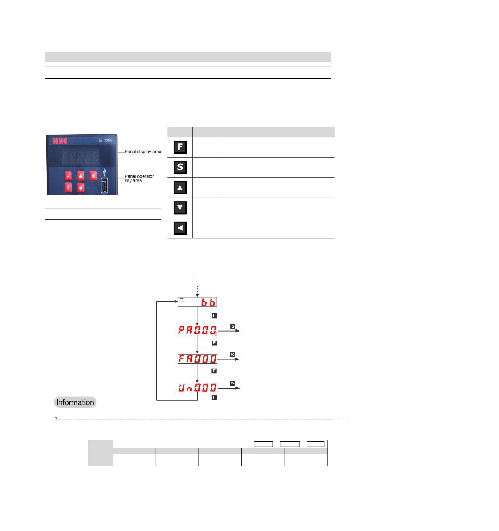
Name and function of panel operator keys
The panel operator consists of a panel display part and panel operator keys.
The panel operator can display the status, perform auxiliary functions, set parameters and monitor the action
of servo drive.
The name and function of the panel operator keys are as follows.
Key
Name
Function
Toggle basic mode:
Function
Status display, auxiliary functions, parameter
key
setting and monitoring
Press this key to display the settings and set
Settings
values of each parameter, enter the parameter
key
setting state and clear the alarm.
Press the UP key to increase the set value
UP key
When the auxiliary function mode JOG is
running, it acts as a forward rotation start key.
Press the DOWN key to decrease the set value
DOWN
When the auxiliary function mode JOG is
8.1.2
Switching of functions
key
running, it acts as a reverse start key.
Press this key to move the selected bit (the
By switching the functions of the panel
Shift key
decimal point of the bit flashes) one bit to the
left.
operator, it is possible to display the
operation status, set parameters, switch
operation commands and other functions.
Functions include status display mode, parameter setting mode, monitoring mode and auxiliary function mode.
After pressing the F key, the modes are switched in the order shown in the following figure.
Power ON
Status display mode
Press
down
Press
User parameter mode
Press
Repeat
down
Press
Auxiliary function mode
Press
down
Press
Monitoring mode
Press
down
After setting Pn52F (monitoring display when power is turned on), the display content after power is turned on
删除[侯]: <sp>
can be set in monitoring display (non-state display).
Please set the un number to be displayed when the power is turned on in Pn52F.
Monitoring display when power is turned on
Speed
Position
Torque
Setting range
Setting Unit
Factory setting
Effective time
Category
Pn52F
Effective
0000 ~ 0FFF
-
0FFF
Setup
immediately
When set to 0FFF [factory setting], the status will be displayed when the power is turned on.
55
8.1.3
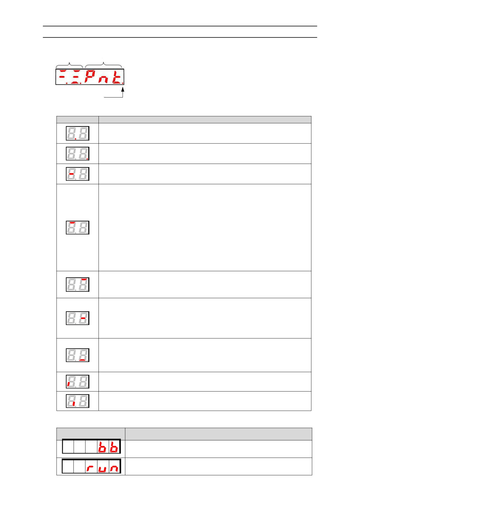
Status display mode
The status is shown below.
Position Data Abbreviation symbol
Off: The current display
is Axis A.
Illumination: the current
display is axis b
■ Display Contents of Bit Data
Display
Meaning
Control power supply ON Display
When the servo control power supply is on, it lights up.
When the servo control power supply is OFF, it goes out.
Power ready display
The main circuit lights up when the power supply is ON. Goes out when the main
circuit power supply OFF.
Base blocking display
Lights when servo is OFF.
Goes out when servo ON.
Speed Consistent Output (/V-CMP) Signal Display (During Speed Control)
If the difference between the speed of the servo motor and the commanded speed is
within the specified value (set by Pn503 or Pn582 and factory set value is 10min-1 or
10mm/s), it will be on and off if it exceeds the specified value. However, the light is
always on during torque control.
Add:
When the command voltage is affected by noise, the "-"symbol on the upper digit on
the left side of the panel operator will flash. Please refer to the following to take
anti-interference measures.
Positioning Complete (/COIN) Display (When Position Control)
If the deviation between the position command and the actual position of the motor is
within the specified value (set by Pn522 and factory setting value is 7 command units),
it will go out if it exceeds the specified value.
Displays the rotation detection output (/TGON) signal
When the rotation speed of the servo motor is higher than the specified value (set by
Pn502 or Pn581, and the factory setting value is 20min-1 or 20mm/s), it will be turned
on, and when it is lower than the specified value, it will be turned off.
Displayed in speed command input (during speed control)
The input speed command lights up when it is higher than the specified value (set by
Pn502 or Pn581, factory setting is 20min-1 or 20mm/s), and goes out when it is lower
than the specified value.
Displayed in command pulse input (during position control)
Lights when command pulse is input. Off when no clear signal is input.
Displayed in torque command input (during torque control)
The input torque command lights up when it is greater than the specified value (10%
of the rated torque), and goes out when it is less than the specified value.
Clear the display in the signal input (during position control)
Lights when a clear signal is input. Off when no clear signal is input.
During high speed bus control
CN3 terminal input status.
During high speed bus control
CN4 terminal input status.
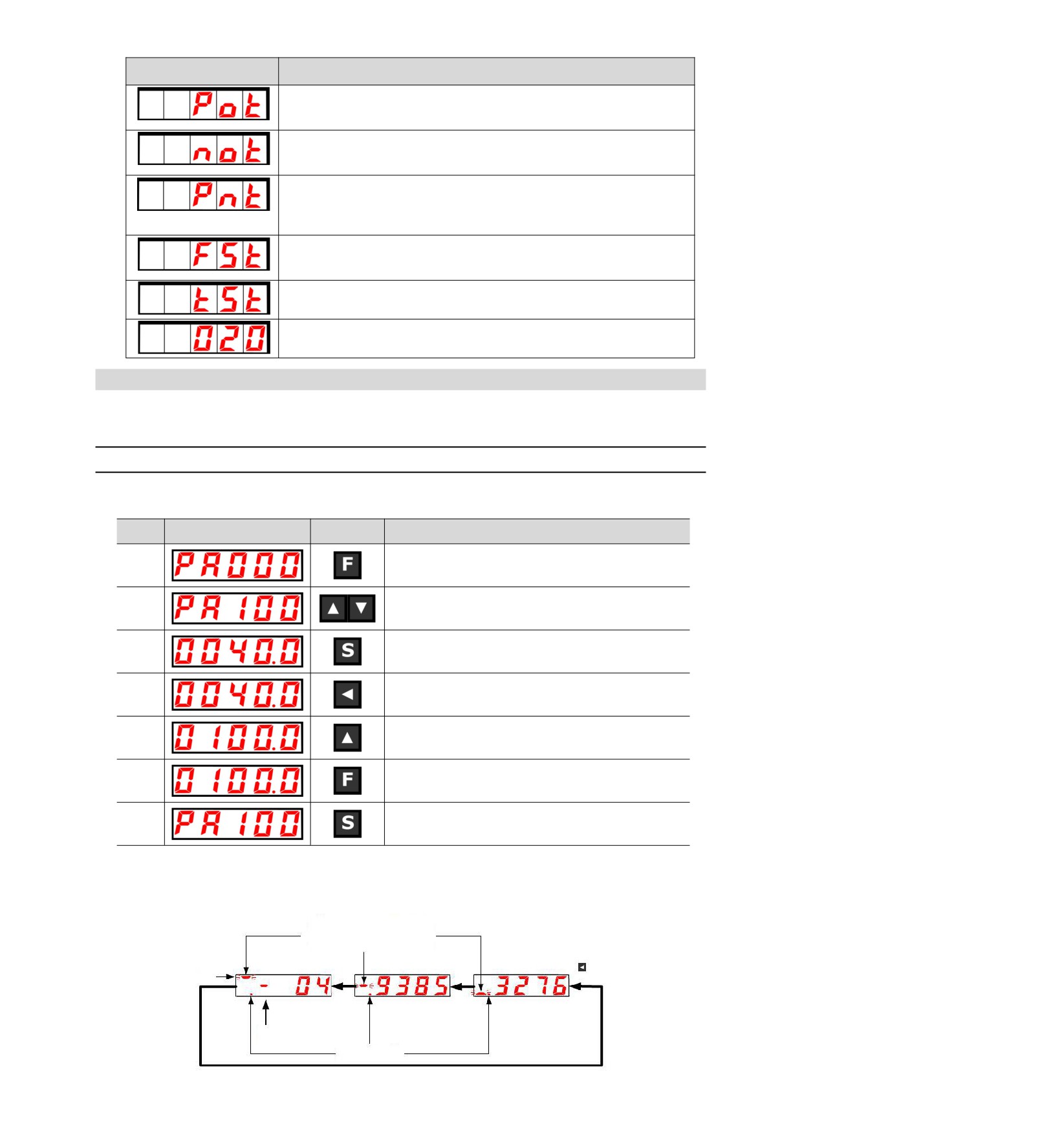
■ Display Contents of Thumbnail Symbols
Abbreviation symbol
Meaning of the contents
Base blockade
Display servo OFF state.
Running
Display servo ON status
56
Abbreviation symbol
Meaning of the contents
Prohibit forward-turning side drive state
Indicates that the inhibit forward drive input (P-OT) signal is in an open
circuit state.
It is forbidden to reverse the side drive state.
Indicates that the inhibit reverse side drive input (N-OT) signal is in an open
circuit state.
The forward and reverse side drive states are prohibited
Indicates that the forward-rotation-prohibited side drive input (P-OT) signal
and the reverse-rotation-prohibited side drive input (N-OT) signal are in an
open circuit state.
Force Stop Status
Indicates that the servo drive is in a forced stop state after receiving a
forced stop input (FSTP) signal.
No motor test function in progress
Indicates a state in which no motor test function is being performed.
Alarm status
Blinking display Alarm number
8.2 Operation of Parameters (PA) in Panel Operator
Displays the number beginning with PA on the panel operator.
The following describes how to set the parameters used in this manual.
8.2.1
Setting Method of "Numerical Setting Type"
The following describes the setting method of numerical setting type, taking the setting value of speed loop
gain (Pn100) from 40.0 to 100.0 as an example.
Operation
Steps
Display after operation
Operation
key
Press the F key to select the parameter mode.
1
In case of dual-axis drive, long press F key more than 3
seconds, and Axis A and Axis B will be switched alternately.
2
Press UP or DOWN to display "Pn100".
3
Press S key to display the current set value of Pn100.
Press the left key to move the flashing digits to make 4
4
flashing. (You can change the number of digits displayed by
blinking.)
5
Press the UP key 6 times to change the set value to "100.0".
After pressing the F key, the value display will flash. In this
6
way, the set value changes from 40.0 to 100.0.
7
Press S key to return to the display of "Pn100".
◆ When the setting range is above 6 bits
Since the panel operator can only display 5 digits, the settings above 6 digits are shown as follows.
The flashing display on the left
indicates the position of the digit
(front bit ● middle bit ● rear bit).
The digit display plus the digit
indicates the parameter value
First 2 digits
Middle 4 digits
Last 4 digits
Press
Press
Press
First 2 digits
"-"is displayed only if it is
with symbol and negative
When the number
is negative, the
decimal is lit up
57
8.2.2
Setting Method of "Function Selection Type"
The function selection type sets various functions by selecting from the functions assigned to each digit of the
display number of the panel operator.
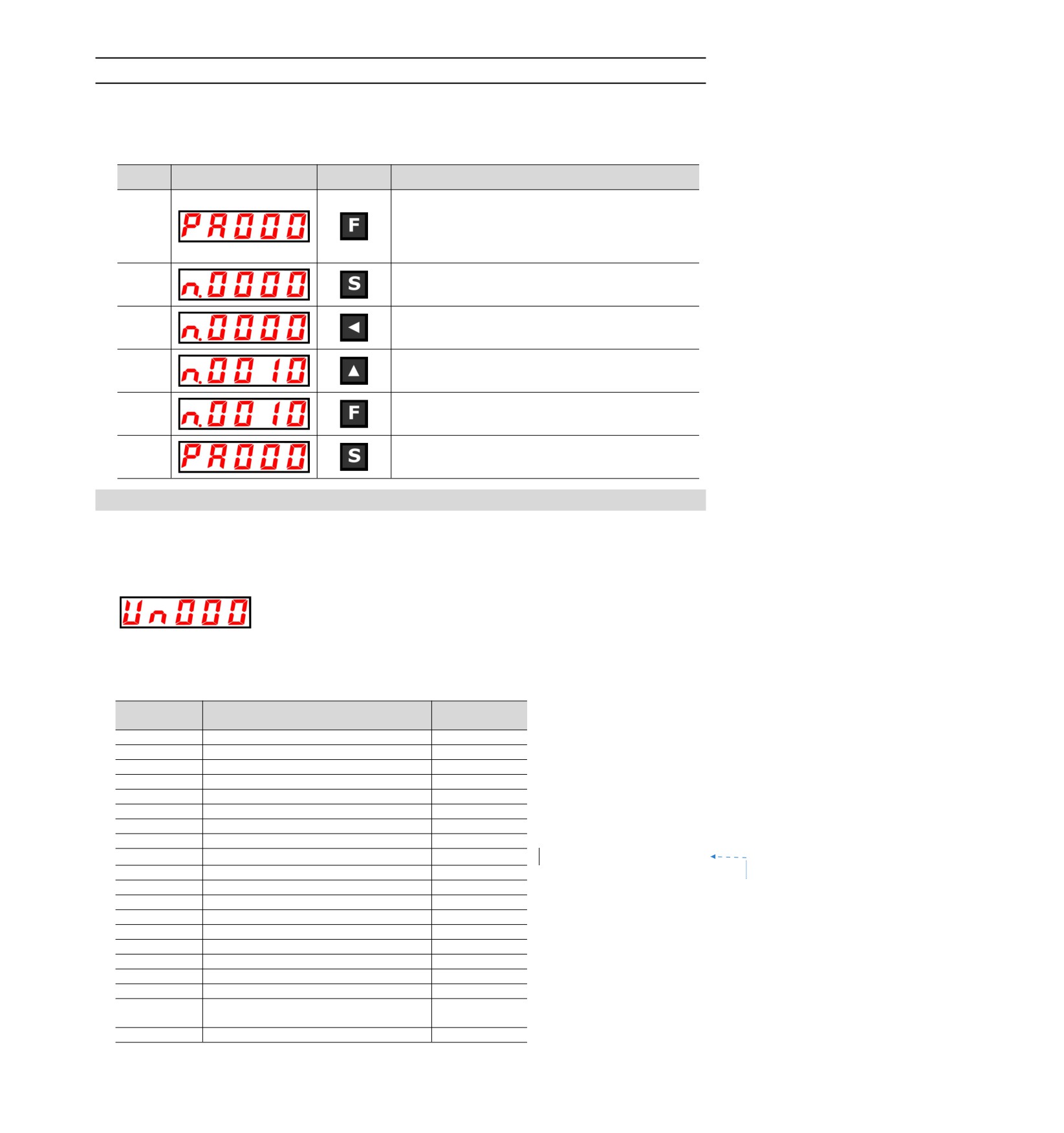
The following describes the setting method of the function selection type, taking the control mode selection
(Pn000.1) of the function selection basic switch (PA000) from speed control to position control as an example.
Operation
Steps
Display after operation
Operation
key
Press the F key to select the parameter mode. If the
parameter number does not show Pn000, press the UP or
DOWN key to show "Pn000".
1
In case of dual-axis drive, long press F key will be used for
more than 3 seconds, and Axis A and Axis B will be switched
alternately.
3
Press S key to display the current set value of Pn000.
Press the left key to move the flashing digits. (You can change
4
the number of digits displayed by blinking. )
Press the UP key once to change the setting value to
5
"n.0010".
(Change speed control to position control.)
After pressing the F key, the value display will flash. In this
6
way, the control mode becomes position control.
7
Press S key to return to the display of "Pn000".
8.3 The operation of the monitor display (Un) in the panel operator
A function of monitoring (displaying) the command value set in the servo drive, the state of input and output
signals, and the internal state of the servo drive.
Displays the number beginning with UA on the panel operator.
Display Example (Motor Speed)
The following describes the basic operation of monitoring display and the discrimination method of display as
a special monitoring number.
■ List of Monitoring and Display Functions
Surveillance
Displaying contents
Unit
number
Un000
Revolving speed of motor
1r/min
Un001
Speed reference
1r/min
Un002
Torque reference
1%
Un003
Rotation angle 1
Encoder pulse
Un004
Rotation angle 2
deg
Un005
Input signal monitoring
Un006
Monitoring of the output signal
Un007
Input Reference pulse speed
1r/min
Un008
Position Error Amount
Command unit
设置格式[侯]: 行距: 固定值 12 磅
Un009
Accumulated load rate
1%
Un00A
Regeneration load ratio
1%
Un00B
DB resistor power consumption
1%
Un00C
Input reference pulse counter
Command unit
Un00D
Feedback pulse counter
Encoder pulse
Un013
Feedback pulse counter
Command unit
Un020
Rated speed of motor
1r/min
Un021
Maximum speed of motor
1r/min
Un040
Absolute encoder Multiturn Data
Coil
Position within 1 coil of absolute value
Un041
Encoder pulse
encoder
Un140
DC BUS voltage
1V
58
8.3.1
Basic operation of monitoring display
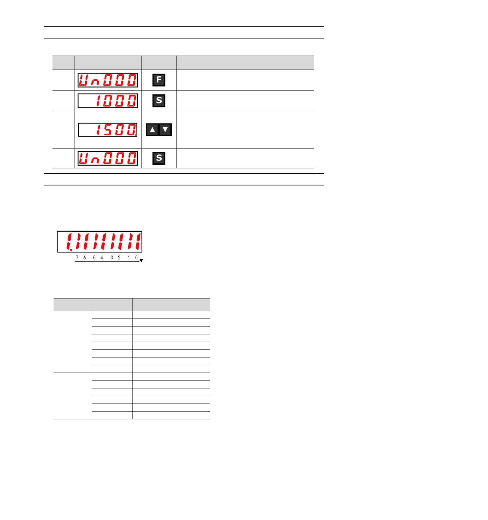
The following description will take Un000 (motor rotation speed) as an example.
Operation
Steps
Display after operation
Operation
key
Press the F key to select the auxiliary function. If the
1
parameter number does not show UA000, press the
UP or DOWN key to show "UA000".
Press S key to display the current motor speed.
2
When there is no red dot in the lower right corner of
the dual-axis drive, the A-axis data is displayed.
When there is a red dot in the lower right corner of
the dual-axis drive, the B-axis data will be displayed.
3
Press the UP or DOWN key to switch the A axis and
the B axis alternately.
3
Press the S key to return to the display of step 1.
8.3.2
Monitoring of input and output signals (Un005/ Un006)
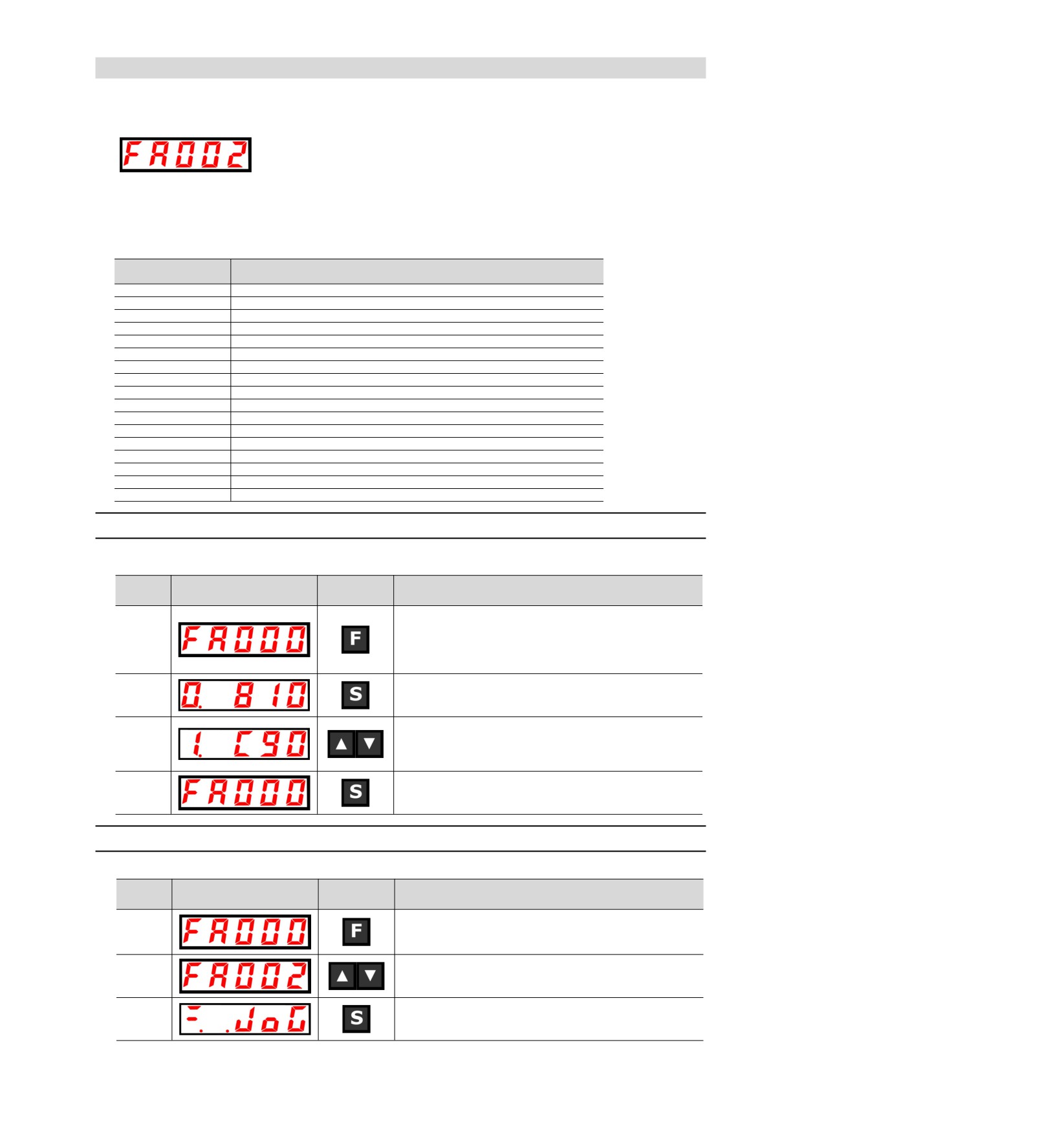
Use Un005/ Un006 to display the assigned signal status in the segment (LED) of the panel operator.
◆ Display discrimination method
< segment (led) >
Up: OFF
Down: ON
Show LED number
The input signal OFF corresponding to the LED number is displayed: the upper segment lights up
The input signal ON corresponding to the LED number is displayed: the lower segment lights up
The distribution table is as follows.
Surveillance
Show LED
Needle number
number
number
0
IN0(CN1-14)
1
IN1(CN1-15)
2
IN2(CN1-16)
3
IN3(CN1-17)
Un005
4
IN4(CN1-39)
5
IN5(CN1-40)
6
IN6(CN1-41)
7
IN7(CN1-42)
0
OUT0(CN1-7, -8)
1
OUT1(CN1-9, -10)
2
OUT2(CN1-11, -12)
Un006
3
OUT3(CN1-32, -33)
4
OUT4(CN1-34, -35)
5
OUT5(CN1-36, -37)
59
8.4 Operation of Auxiliary Function (FA) in Panel Operator
The auxiliary function is used to perform functions related to setting and adjusting the servo drive.
Displays the number beginning with FA on the panel operator.
Display Example (JOG Run)
The following describes the operation steps when using the panel operator. Please refer to the contents of
each function for confirmation items and relevant parameters before execution.
■ List of auxiliary function execution modes
Auxiliary function
Function
number
FA000
Display Alarm History
FA002
JOG
FA003
Origin search
FA004
JOG run
FA005
Initialization parameter
FA006
Clear Alarm History
FA008
Reset Absolute Encode
FA009
Autotune Analog (Speed/ Torque) Reference Offset
FA00A
Manually adjust the speed reference offset
FA00B
Manually adjust torque reference offset
FA00E
Autotune Motor Current Detection Signal Offset
FA010
Write inhibit setting of parameters
FA011
Displays the motor model information.
FA012
Displays the servo software version
FA203
One-parameter tuning.
FA206
Easy FFT
FA208
Load inertia/mass detection
8.4.1
Display of alarm records (FA000)
Please refer to the following contents besides the operation steps
Operation
Steps
Display after operation
Operation
key
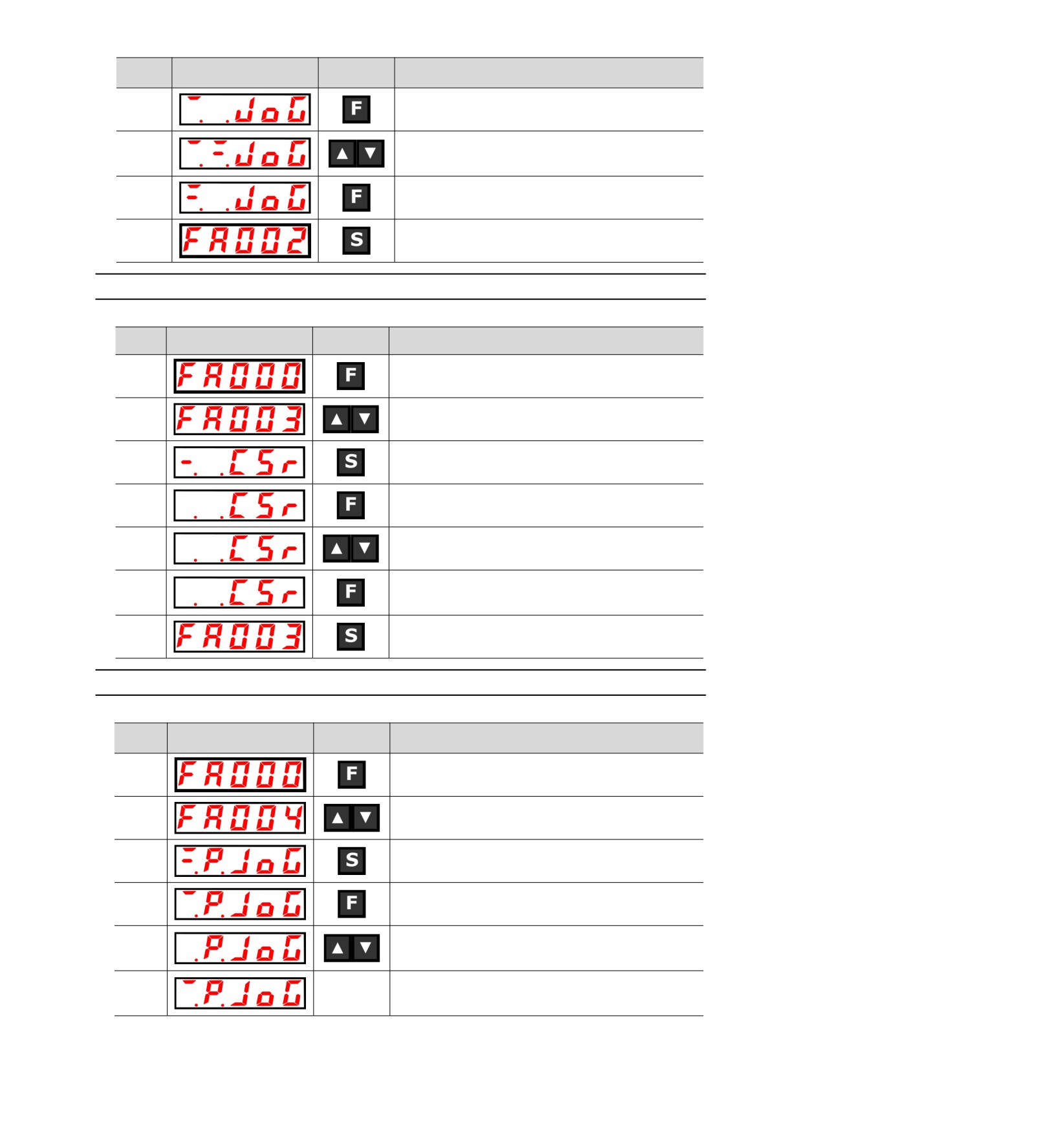
Press the F key to select the auxiliary function. If the
parameter number does not show FA000, press the UP or
1
DOWN key to show "FA000".
In case of dual-axis drive, long press F key more than 3
seconds, and Axis A and Axis B will be switched alternately.
2
Press S key to display the latest alarm.
Every time the DOWN key is pressed, an old alarm is
displayed back. Each time the UP key is pressed, a new alarm
3
will be displayed in the future. The larger the number in the left
digit, the older the alarm displayed.
4
Press the S key again to return to the display of "FA000".
8.4.2
JOG operation (FA002)
Please refer to the following contents besides the operation steps
Operation
Steps
Display after operation
Operation
key
Press the F key to select the auxiliary function.
1
In case of dual-axis drive, long press F key more than 3
seconds, and Axis A and Axis B will be switched alternately.
2
UP or DOWN key display "FA002".
Press S key, and the display content is shown in the left
3
figure.
60
Operation
Steps
Display after operation
Operation
key
4
Press F key to enter servo ON state.
Press the UP key
(forward rotation) or the DOWN key
5
(reverse rotation), during which the servo motor rotates at the
speed set by Pn304 or Pn383.
6
Press MODE/SET key to enter servo OFF state.
7
Press the S key again to return to the display of "FA002".
8.4.3
Origin search (FA003)
Please refer to the following contents besides the operation steps
Operation
Steps
Display after operation
Operation
key
1
Press the F key to select the auxiliary function.
2
UP or DOWN key display "FA003".
3
Press S key, and the display content is shown in the left figure.
4
Press F key to enter servo ON state.
Press the UP key and the servo motor will rotate forward.
5
Press the DOWN key and the servo motor will reverse.
After the origin search of the servo motor is completed, it will
6
change to flashing display. At this time, the servo motor enters
the servo lock state at the origin within 1 coil of the encoder.
7
Press the S key again to return to the display of "FA003".
8.4.4
Program JOG run (FA004)
Please refer to the following contents besides the operation steps
Operation
Steps
Display after operation
Operation
key
1
Press the F key to select the auxiliary function.
2
UP or DOWN key display "FA004".
3
Press S key, and the display content is shown in the left figure.
4
Press F key to enter servo ON state.
Press the UP key or DOWN key that conforms to the initial
5
operation direction of the operation mode, and the operation
will start after the set waiting time.
If the program JOG runs to an End, it will flash "End" and return
6
-
to the display in the left Figure.
If you press the S key, return to step 2.
61
8.4.5
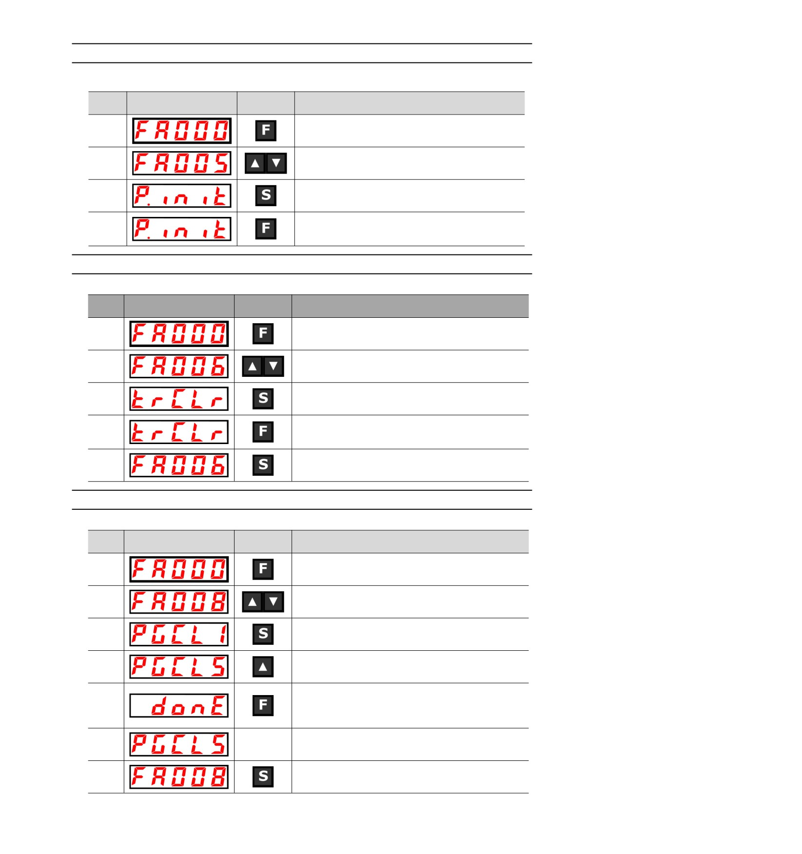
Initialization of parameter settings (FA005)
Please refer to the following contents besides the operation steps
Operation
Steps
Display after operation
Operation
key
1
Press the F key to select the auxiliary function.
2
UP or DOWN key display "FA005".
Press S key, and the display content is shown in the
left
3
figure.
Press F key to initialize parameters.
4
After initialization is completed, flash "donE" and return to the
display on the left.
8.4.6
Deletion of Alarm records (FA006)
Please refer to the following contents besides the operation steps
Operation
Steps
Display after operation
Operation
key
1
Press the F key to select the auxiliary function.
2
UP or DOWN key display "FA006".
3
Press S key, and the display content is shown in the left figure.
Press F to delete the alarm record.
4
"donE" will flash and return to the display on the left after the
deletion is completed.
5
Press the S key again to return to the display of "FA006".
8.4.7
Absolute value encoder Setup(initialization)(FA008)
Please refer to the following contents besides the operation steps
Operation
Steps
Display after operation
Operation
key
1
Press the F key to select the auxiliary function.
2
UP or DOWN key display "FA008".
Press S key, and the display content is as shown in the left
3
figure, and "PGCL1” is displayed.
4
Press and hold the UP key until PGCL5 is displayed.
Press F key to start setting (initializing) the absolute value
encoder.
5
"donE" flashes for about
1
second after the setting
(initialization) is completed.
6
-
Return to the display of "PGCL5” after "donE" is displayed.
7
Press the S key again to return to the display of "FA008".
62
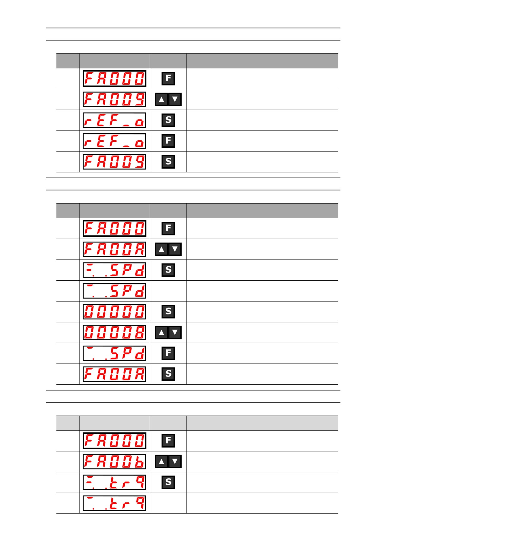
8.4.8
Automatic Adjustment of Analog (Speed and Torque) Command Bias (FA009)
Please refer to the following contents besides the operation steps
Operation
Steps
Display after operation
Operation
key
1
Press the F key to select the auxiliary function.
2
UP or DOWN key display "FA009".
Press S key, and the display content is as shown in the left
3
figure, and "rEF_o” is displayed.
"donE" will flash and then switch to the display on the left when
4
the f key is pressed.
5
Press the S key again to return to the display of "FA009".
8.4.9
Manual Adjustment of Speed Command Bias (FA00A)
Please refer to the following contents besides the operation steps
Operation
Steps
Display after operation
Operation
key
1
Press the F key to select the auxiliary function.
2
UP or DOWN key display "FA00A".
3
Press S key, and the display content is shown in the left figure.
Turn ON the servo from the outside to display the content on
4
-
the left.
5
Press the S key to display the current offset.
Press the UP or DOWN key to adjust and stop the servo motor.
6
This value is the offset.
"donE" will flash and then switch to the display on the left when
7
the f key is pressed.
8
Press the S key again to return to the display of "FA00A".
8.4.10 Manual Adjustment of Torque Command Bias (FA00B)
Please refer to the following contents besides the operation steps
Operation
Steps
Display after operation
Operation
key
1
Press the F key to select the auxiliary function.
2
UP or DOWN key display "FA00b".
3
Press S key, and the display content is shown in the left figure.
Turn ON the servo from the outside to display the content on
4
-
the left.
63
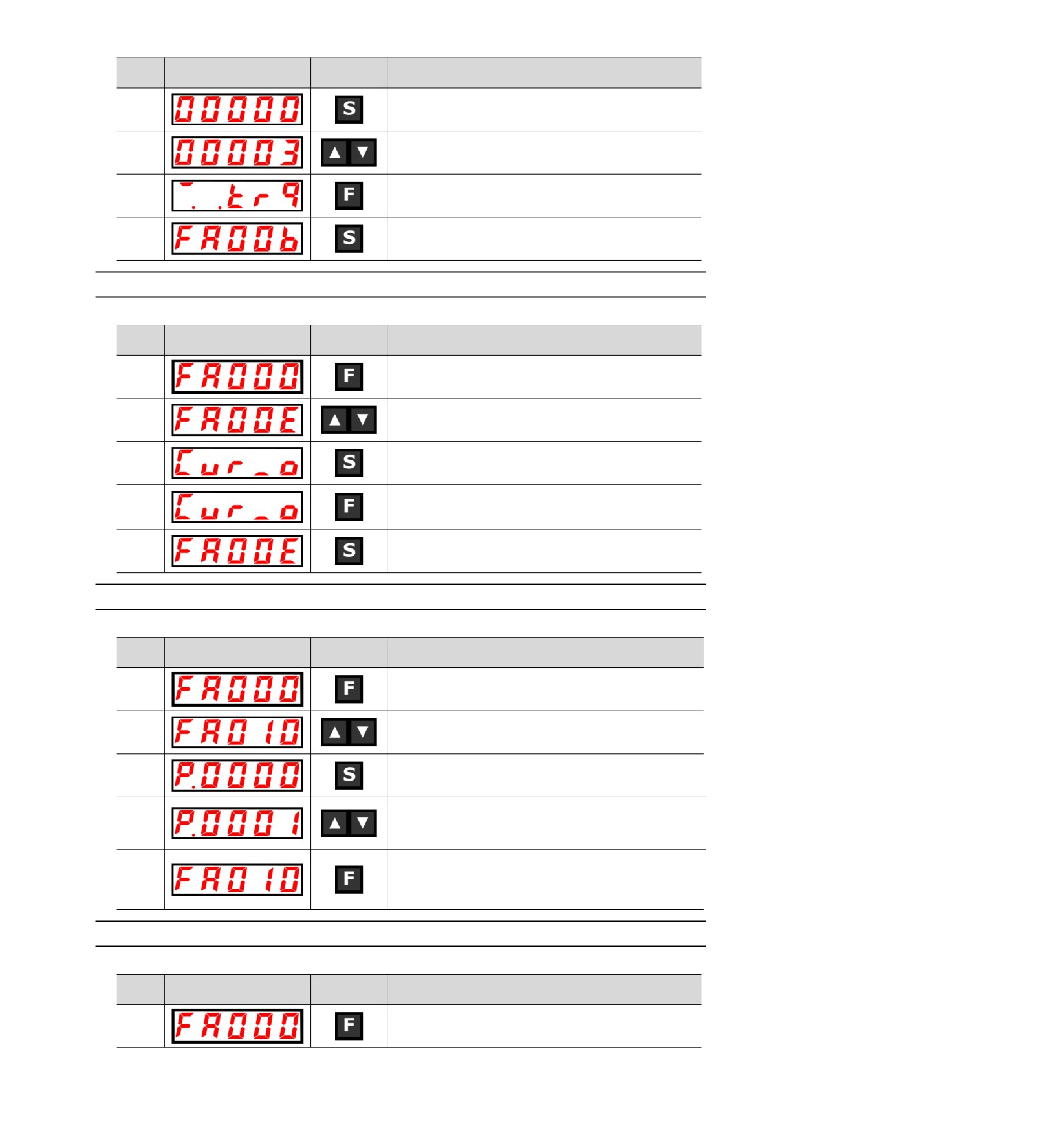
Operation
Steps
Display after operation
Operation
key
5
Press the S key to display the current offset.
Press the UP or DOWN key to adjust and stop the servo motor.
6
This value is the offset.
"donE" will flash and then switch to the display on the left when
7
the f key is pressed.
8
Press the S key again to return to the display of "FA00b".
8.4.11 Automatic Adjustment of Offset of Motor Current Detection Signal(FA00E)
Please refer to the following contents besides the operation steps
Operation
Steps
Display after operation
Operation
key
1
Press the F key to select the auxiliary function.
2
UP or DOWN key display "FA00E".
3
Press S key, and the display content is shown in the left figure.
When the F key is pressed, the offset is automatically adjusted.
4
After the adjustment is completed, the left display will be
returned after flashing "donE".
5
Press the S key again to return to the display of "FA00E".
8.4.12 Write inhibit setting of parameters(FA010)
Please refer to the following contents besides the operation steps
Operation
Steps
Display after operation
Operation
key
1
Press the F key to select the auxiliary function.
2
UP or DOWN key display "FA010".
3
Press S key, and the display content is shown in the left figure.
Press the UP or DOWN key to set to any of the following values.
4
"P.0000": Allowed to Change [Factory Settings]
"P.0001": no change
Press F to confirm the setting. After the setting is completed,
flash "donE" and return to the display on the left.
5
(Note) "Error" is displayed if it is set to a value other than
"P.0000" and "P.0001".
8.4.13 Displays the motor model (FA011)
Please refer to the following contents besides the operation steps
Operation
Steps
Display after operation
Operation
key
1
Press the F key to select the auxiliary function.
64
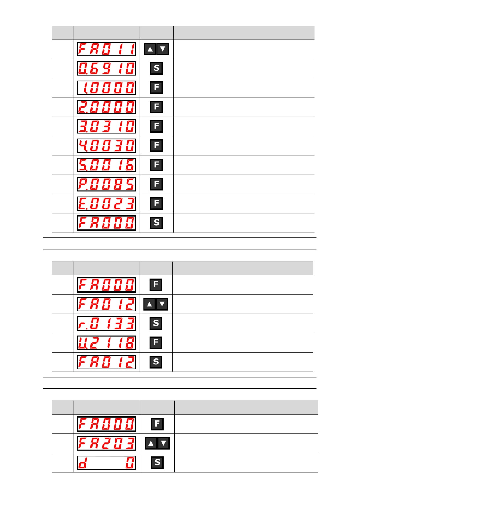
Operation
Steps
Display after operation
Operation
key
2
UP or DOWN key display "FA011".
Press the S key to display the current motor code. The display
3
content will be shown in the left figure.
4
Press F key to display the current servo internal parameter 1.
5
Press F key to display the current servo internal parameter 2.
6
Press F key to display the current servo internal parameter 3.
7
Press F key to display the current servo internal parameter 4.
8
Press F key to display the current servo internal parameter 5.
Press F key, the current motor capacity is 850W,and the unit is
9
10W.
10
Press F key, the encoder resolution.
11
Press the S key again to return to the display of "FA011".
8.4.14 Display software version (FA012)
Please refer to the following contents besides the operation steps
Operation
Steps
Display after operation
Operation
key
1
Press the F key to select the auxiliary function.
2
UP or DOWN key display "FA012".
Press S to display the servo-driven software version, as shown
3
in the left figure.
4
Press the F key to display the FPGA version.
5
Press the S key again to return to the display of "FA012".
8.4.15 Single parameter adjustment (FA203)
Please refer to the following contents besides the operation steps
Operation
Steps
Display after operation
Operation
key
1
Press the F key to select the auxiliary function.
2
UP or DOWN key display "FA203".
3
Press S key, and the display content is shown in the left figure.
65
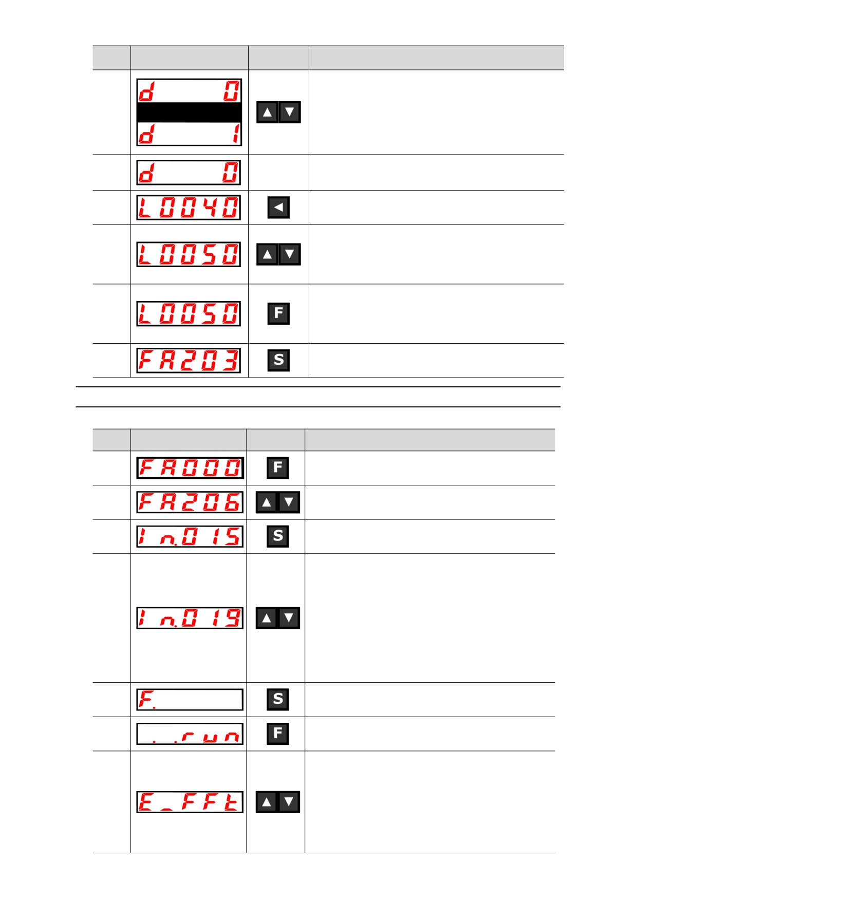
Operation
Steps
Display after operation
Operation
key
Press the UP or DOWN key to set the adjustment mode.
TUNING MODE(Adjust the strength of the setting)
4
0: Pay attention to the adjustment of stability.
1. Pay attention to responsive adjustment.
(Note) TYPE (Rigid type) is fixed as "2".
In the non-servo ON state, a servo ON (/S-ON) signal is input
5
-
from the upper device.
In the servo ON state, proceed to step 6.
Press S key to display single parameter gain data as shown on
6
the left.
When the UP key or DOWN key is operated to change the single
parameter gain value, the actual servo gains (Pn100, Pn101,
7
Pn102, Pn401) also change simultaneously.
This function judges the response result by the customer, and
the adjustment ends when the customer is satisfied.
Press F key to save the calculated 4 gains into the parameters.
After the adjustment is normally completed, the left display will
8
be returned after flashing "donE".
(Note) Please enter Step 9 when the calculated gain is directly
ended without saving.
9
Press the S key again to return to the display of "FA203".
8.4.16 EasyFFT(Fn206)
Please refer to the following contents besides the operation steps
Operation
Steps
Display after operation
Operation
key
1
Press the F key to select the auxiliary function.
2
UP or DOWN key display "FA206".
Press S key, the display content is as shown in the left figure,
3
and enter the command amplitude setting mode.
Press the UP or DOWN key to set the command amplitude.
Command amplitude setting range: 1-800
(Note) 1. When setting EasyFFT for the first time, do not change
the setting of command amplitude, and start from the
initial setting of "15".If the command amplitude is
increased, the detection accuracy will be improved, but
4
the vibration and noise generated by the machine will
become larger in a short time. Please gradually
increase the amplitude value and make changes while
observing the situation when changing the command
amplitude.
2. The set command amplitude is stored in Pn456.
Press and hold the S key to enter the operation preparation
5
state.
Press F key to enter servo ON state. At this time, if you want to
6
turn OFF the servo, press F key. Return to step 5.
In the servo ON state, press the UP or DOWN key, and the
servo motor will rotate forward and reverse several times with a
maximum amplitude of 1/4 rotation (within 10mm in the case of
linear servo motor). The running time is about 2 seconds. During
operation, the display on the left will flash.
7
(Note) 1. Press the F key to return to step 5 when stopping the
action.
2. The servo motor moves slightly and makes a sound at
the same time. For safety, please do not approach the
machine.
66
Operation
Steps
Display after operation
Operation
key
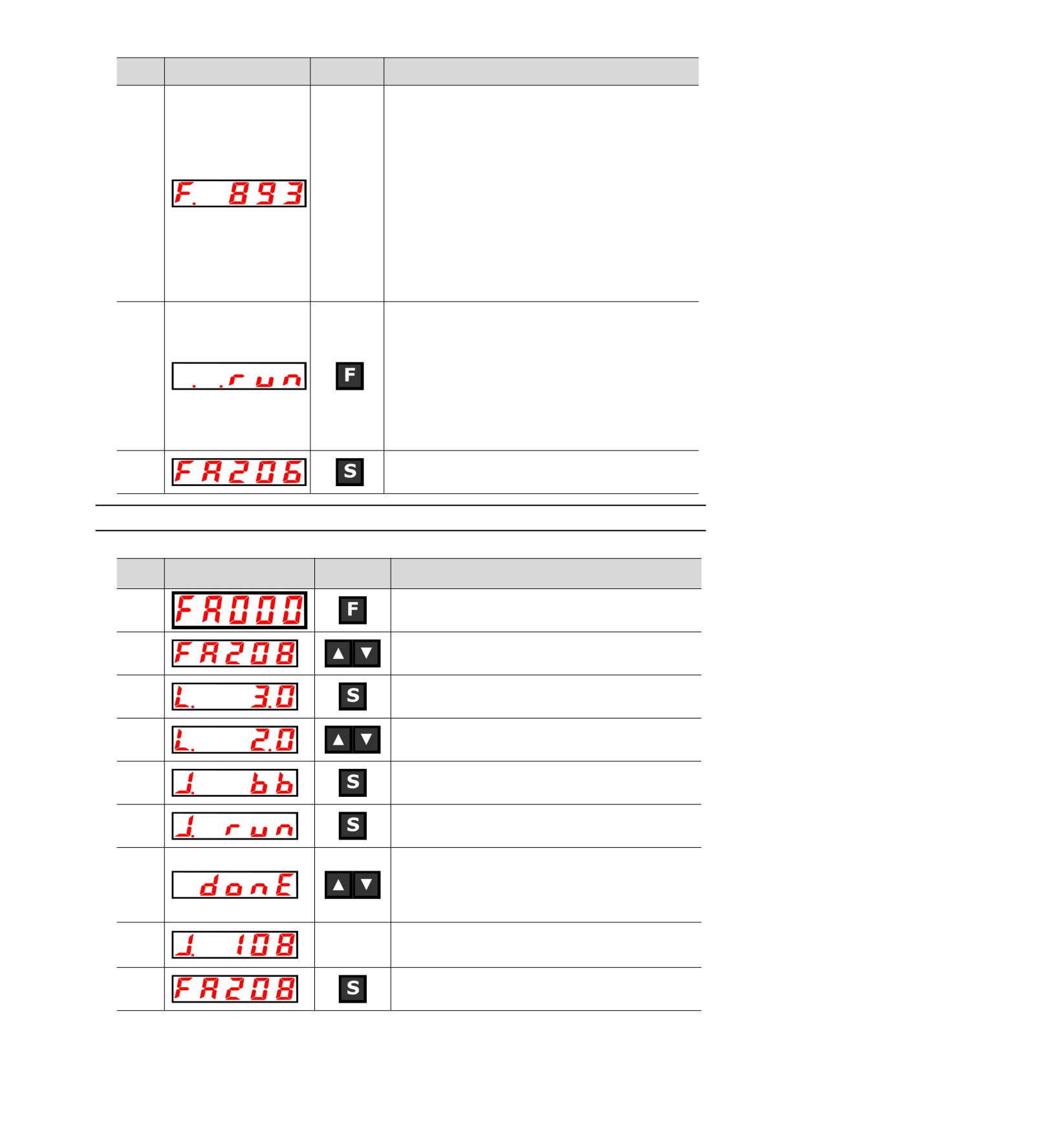
After the detection process is normally completed, the "E_FFt"
display stops blinking and shows the detected resonance
frequency. If the check-out fails, "F----" is displayed.
When setting the check-out result, you must proceed to step 9.
If only the resonance frequency is confirmed without setting the
detection result, press the S key to return to step 2.
<Important>
Even if the detection ends normally, if the running time exceeds
8
--
2 seconds, the detection accuracy may be insufficient. If the
command amplitude is increased to slightly greater than "15"
and then executed again, the detection accuracy may be
improved. However, after the command amplitude is increased,
the vibration and noise generated by the machine will become
larger in a short time. Please gradually increase the amplitude
value and make changes while observing the situation when
changing the command amplitude.
Press F key and it will be automatically set as the best notch
filter corresponding to the detected resonant frequency. After the
notch filter is normally set, "donE" flashes and returns to the left
display. When the 1st notch filter frequency has been set, the
2nd notch filter frequency (Pn40C) will be automatically set in
9
(PN 408.0 = 1).Press F again to return to step 5.
(Note) 1. When the notch filters of section 1 and section 2 have
been set, it is not possible to set the notch filter at
(Pn408= n.□1□1).
2. When the notch filter frequency detected by this
function is not used, Pn408.0= 00 is set.
10
Press the S key again to return to the display of "FA206".
8.4.17 Load Inertia/Mass Detection (FA208)
Please refer to the following contents besides the operation steps
Operation
Steps
Display after operation
Operation
key
1
Press the F key to select the auxiliary function.
2
UP or DOWN key display "FA208".
Press S key, and the display content is as shown in the left
3
figure. Enter the load inertia/mass pushing distance setting.
Press the UP or DOWN key to set the moving distance.
4
Unit: coil (rotating motor) mm (linear motor)
Press and hold the S key to enter the operation preparation
5
state.
Press S key to enter servo ON state. At this time, if you want to
6
turn OFF the servo, press S key. Return to step 5.
Press the UP or DOWN key in the servo ON state, and the
servo motor will rotate forward and reverse several times
7
within the set moving distance (within 10mm in the case of
linear servo motor). The running time is about 8 seconds.
During operation, the display on the left will flash.
The flicker is stopped and the detected load inertia/mass
8
--
percentage is displayed after the detection process is normally
completed. If the check-out fails, "J.----" is displayed.
9
Press the S key again to return to the display of "FA208".
67
Chapter 9
Maintenance
9.1 Inspection and component replacement
The inspection of servo drive and component replacement will be described below.
9.1.1
Inspection
Servo drive does not need routine inspection, but the following items need to be inspected at least once a
year.
Inspection
Check interval
Maintenance essentials
Handling in case of failure
item
Appearance
Please wipe with cloth or clean with air
No garbage, dust, oil stains, etc.
inspection
At least once a
gun.
Looseness of
year
Terminal blocks, connector mounting
Please tighten it further.
screws
screws, etc. shall not be loosened.
9.1.2
Battery Replacement
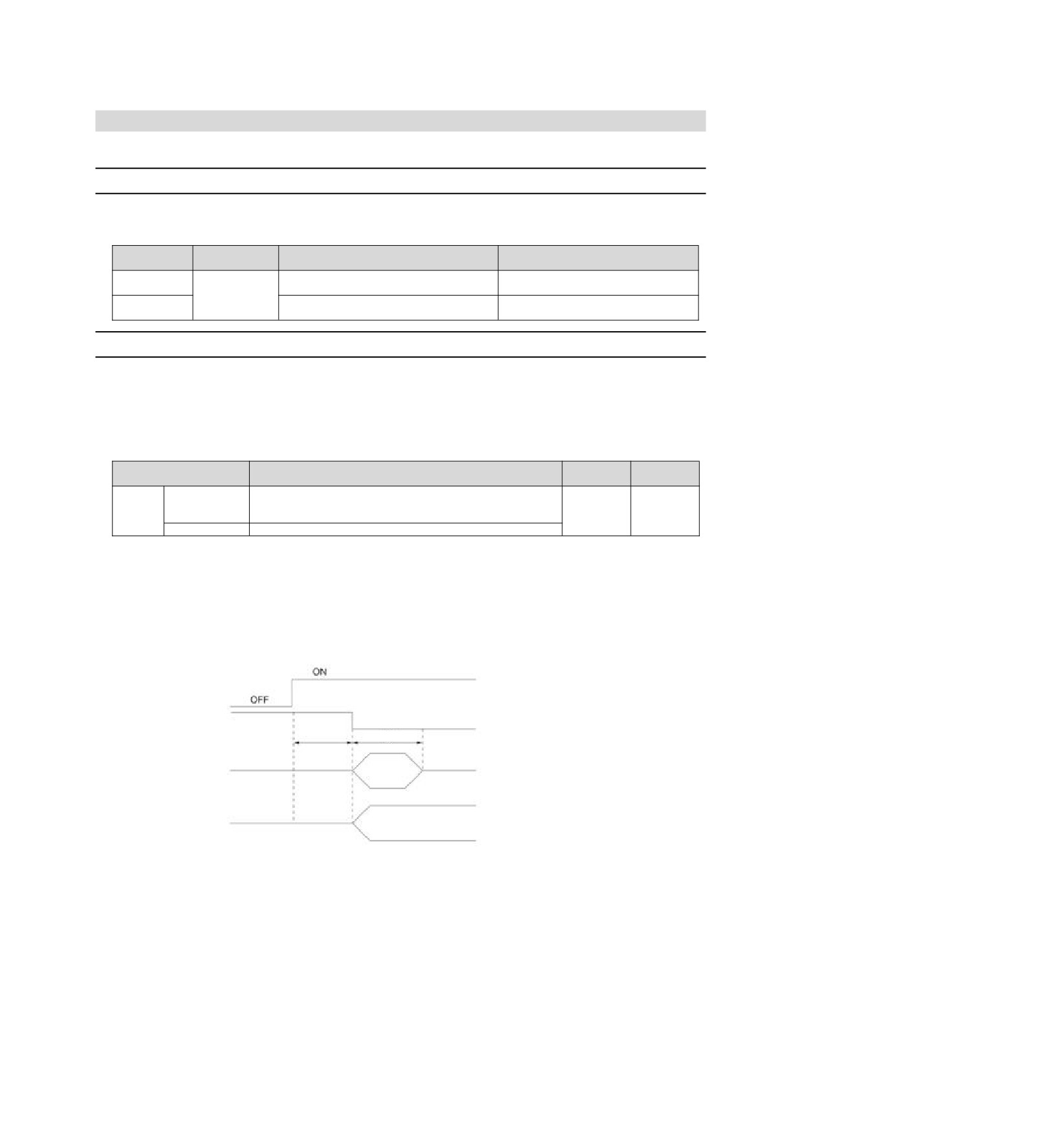
When the battery voltage is below about 3V, "encoder battery alarm (A.830)" or "absolute encoder battery
abnormality alarm (A.930)" will be displayed.
When this alarm or warning is displayed, the battery needs to be replaced.
Battery Alarm/Warning Settings
Whether to display alarm or warning is set by alarm/warning of battery undervoltage (Pn 008 = n. X).
Effective
Parameter
Meaning
Category
time
n.0
[Factory
An alarm is displayed when the battery voltage drops (A.830).
Power
Pn008
Setup
setting]
restart
n.1
An alarm is displayed when the battery voltage drops (A.930).
yWhen Pn008=n.0 is set
yAfter switching on the power supply and outputting a servo alarm (ALM) signal for up to 5 seconds, monitor
the battery voltage for 4 seconds.
Even if the battery voltage drops below the specified value after 4 seconds, no alarm will be displayed.
yWhen Pn008 = n. 1 is set
After the power supply is turned on and the servo alarm (ALM) signal is output for up to 5 seconds, the
battery voltage will always be monitored.
Control power
ALM signal
Alarm status
Normal status
Maximum 5
seconds
4 seconds
When the alarm
shows Pn008 = n.
0
When the alarm
shows Pn008 = n.
1
Battery voltage monitoring
Battery Replacement Steps
◆ When installing the battery on the upper device
1. Only connect to the servo drive control power supply.
2. Remove the used battery and install the new battery.
3. Please turn off the servo drive control power supply to cancel the "A.830 (Encoder Battery Alarm)" display.
4. Connect to the servo drive control power supply again.
5. Confirm that the alarm display disappears and the servo drive can operate normally.
68
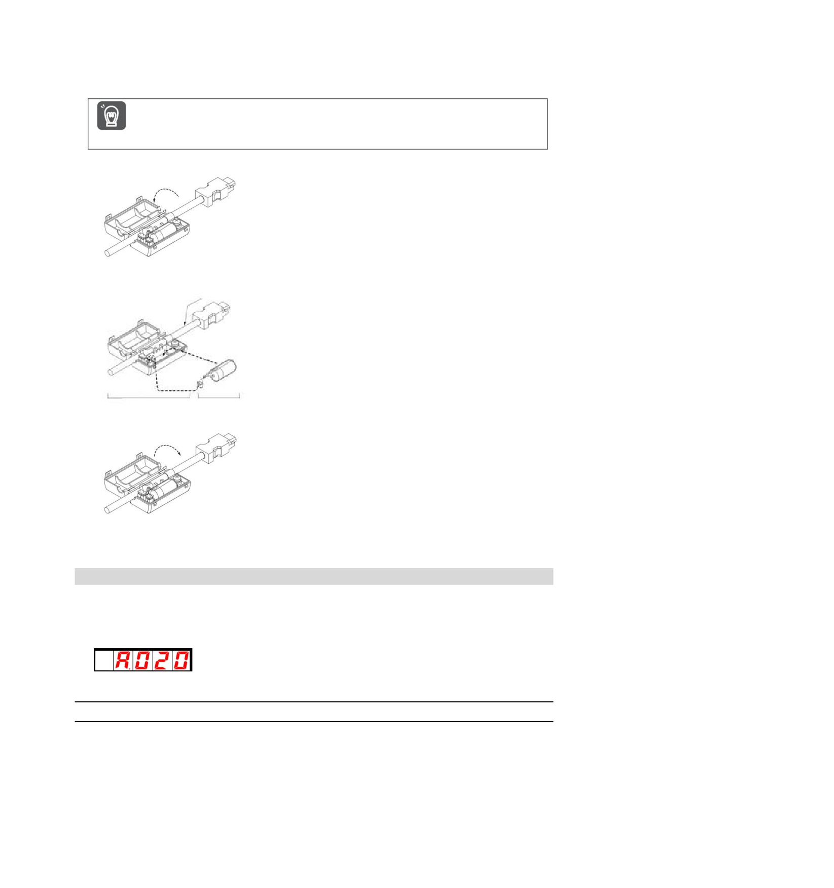
◆ When using encoder cable with battery unit
1. Only connect to the servo drive control power supply.
If the battery is removed after the servo drive control power supply is OFF (including when the encoder
cable is removed), the memory data in the absolute value encoder will be lost.
Important
2. Open the outer cover of the battery unit
3. Remove the used battery and install the new battery.
Encoder cable for absolute value encoder
Servo unit side connector
Installation of lithium battery
Battery unit
Lithium battery
4. Cover the outer cover of the battery unit.
5. Please turn off the servo drive power supply to cancel the "A.830 (Encoder Battery Alarm)" display.
6. Connect to the servo drive power supply again.
7. Confirm that the alarm display disappears and the servo drive can operate normally.
9.2 Alarm display
When the servo drive is abnormal, the LED of the panel display unit displays the Alarm number.
The Alarm number that is occurring is shown below and is displayed in the panel display area.
Example: When "A.20" alarm occurs, it will display:
9.2.1
Warning list
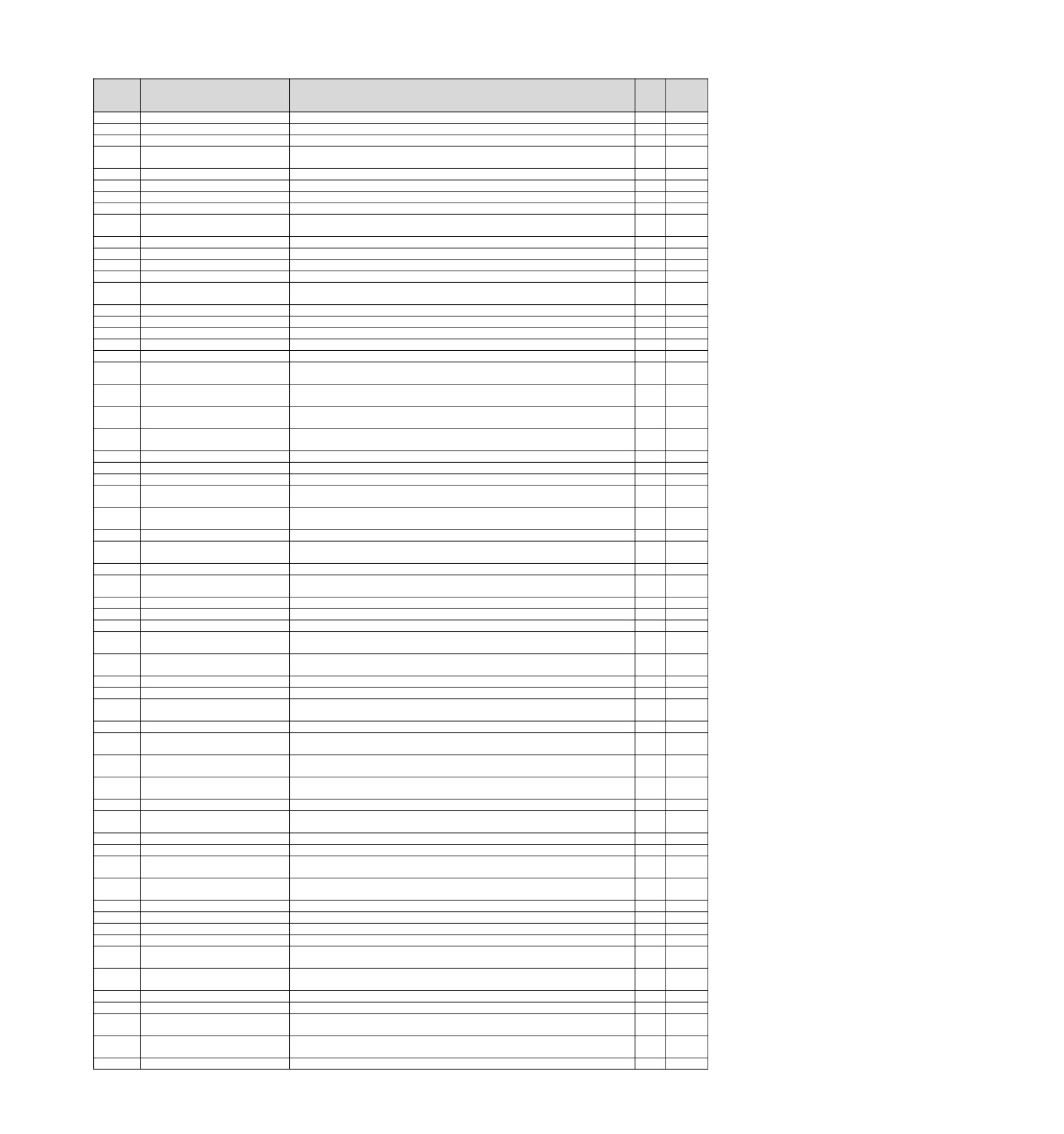
The Alarm name, Alarm content, stop method when alarm occurs and whether alarm reset is possible
according to the order of Alarm numbers are listed in the alarm list lists.
Whether the alarm can be reset
Yes: the alarm can be released through alarm reset. However, if the alarm factor still exists, it cannot be
released.
No: The alarm cannot be released.
69
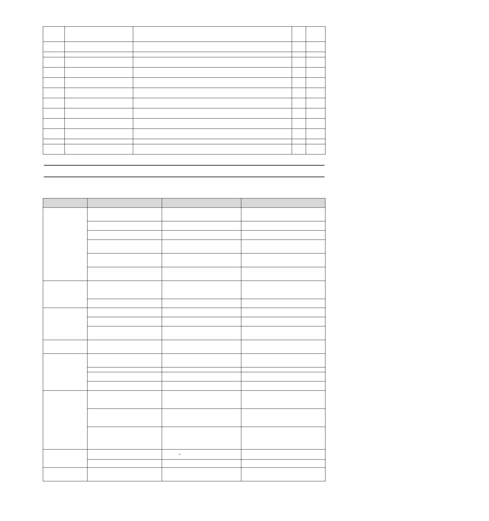
Alarm list
Alarm
Alarm
Alarm
Alarm name
Alarm content
stop
reset
number
mode
Whether
A.020
Parameter and check exceptions
The data of internal parameters of servo drive is abnormal.
Gr.1
No
A.021
Parameter format exception
The data format of internal parameters of servo drive is abnormal.
Gr.1
No
A.022
System and check exceptions
The data of internal parameters of servo drive is abnormal.
Gr.1
No
The main circuit detection unit is
A.030
Various detected data of the main circuit are abnormal.
Gr.1
May
abnormal.
A.040
Parameter setting exception
Out of set range.
Gr.1
No
A.042
Parameter combination exception
The combination of multiple parameters is out of the set range.
Gr.1
No
A.050
Combination error
Outside the combinable motor capacity range.
Gr.1
May
A.051
The product does not support Alarms
Unsupported products are connected.
Gr.1
No
A servo ON command is sent from the upper device after performing the auxiliary
A.0b0
Servo ON command invalid alarm
Gr.1
May
function of energizing the motor.
A.100
Overcurrent detection
Power transistor overcurrent or heat sink overheating.
Gr.1
No
A.101
Motor overcurrent detection
A current exceeding the allowable current flows through the motor.
Gr.1
No
A.300
Regeneration anomaly
Regenerative faults.
Gr.1
May
A.320
Regeneration overload
Regeneration overload occurred.
Gr.2
May
The setting of AC power input/DC power input is incorrect. The power cord is wired
A.330
Main circuit power supply wiring error
Gr.1
May
incorrectly.
A.400
Overvoltage
The main circuit DC voltage is abnormally high.
Gr.1
May
A.410
Under voltage
The DC voltage of the main circuit is insufficient.
Gr.2
May
A.510
Over speed
The motor speed exceeds the maximum speed.
Gr.1
May
A.520
Vibration alarm
Abnormal vibration of motor speed is detected.
Gr.1
May
A.521
Automatically adjust alarm
Vibration is detected in the automatic adjustment of the adjustment-free function.
Gr.1
May
Incorrect ESM requires exception
A.600
A state transition request that cannot be converted from the current state was received.
Gr.1
May
protection
Undefined ESM requires exception
A.601
An undefined state transition request was received.
Gr.1
May
protection
Boot state requires exception
A.602
Bootstrap state transition request received.
Gr.1
May
protection
PLL has not completed exception
The phase combination of communication and servo is still unable to be completed after
A.603
Gr.1
May
protection
synchronization is started for 1s.
A.604
PDO watchdog exception protection
When SP or OP, bit10 of ESC register 0200h is not ON within the specified time.
Gr.1
May
A.605
ESC hardware initialization error
ESC hardware initialization error.
Gr.1
May
A.606
PLL exception protection
ESM status is SP or OP, and the communication and servo phases do not match.
Gr.1
May
Abnormal protection of synchronous
SYNC0 or IRQ interrupt processing timed out after synchronization processing was
A.607
Gr.1
May
signals
completed.
The same period set abnormal
A.610
Unsupported synchronization period (SYNC0) is set.
Gr.1
May
protection
A.611
Mailbox Set Exception Protection
SM0/1 of mailbox is set incorrectly.
Gr.1
May
PDO Watchdog Sets Abnormal
A.614
PDO watchdog setting error.
Gr.1
May
Protection
A.615
DC set exception protection
DC setting error.
Gr.1
May
SM event mode setting exception
A.616
Unsupported SM events are set.
Gr.1
May
protection
A.617
SM2/3 Set Abnormal Protection
SM2/3 is set to an incorrect value.
Gr.1
May
A.620
CAN controller hardware error
CAN transceiver hardware error
Gr.1
May
A.621
CANopen heartbeat timed out
Monitor heartbeat time loss or timeout
Gr.1
May
CANopen synchronization frame
A.622
Synchronization frame lost or timed out
Gr.1
May
timed out
TxPDO
allocates
exception
A.650
The data size of the TxPDO map exceeds 32 bytes.
Gr.1
May
protection.
A.651
RxPDO assigns exception protection.
The data size of the RxPDO map exceeds 32 bytes.
Gr.1
May
A.652
Lost link exception protection
After ESM leaves Init state, Port0 or 1 appears lost link state.
Gr.1
May
Overload
(instantaneous maximum
It runs for several seconds to tens of seconds with a torque greatly exceeding the rated
A.710
Gr.2
May
load)
value.
A.720
Overload (continuous maximum load)
Continuous operation is carried out with torque exceeding the rated value.
Gr.1
May
Due to the action of DB (dynamic brake), the operating energy exceeds the capacity of
A.730/1
DB overload
Gr.1
May
DB resistor.
Impulse current limiting resistor
A.740
The main circuit power on frequency is too high.
Gr.1
May
overload
The power supply of the encoder is completely exhausted and the position data is
A.810
Encoder backup alarm
Gr.1
No
cleared.
A.820
Encoder and check alarm
The sum check result of encoder memory is abnormal.
Gr.1
No
The voltage of the battery drops below the specified value after switching on the control
A.830
Encoder battery alarm
Gr.1
May
power supply.
A.840
Encoder data alarm
Data inside encoder is abnormal.
Gr.1
No
A.850
Encoder overspeed
When the power supply is ON, the encoder rotates at high speed.
Gr.1
No
MECHATROLINK communication
A.b6A
MECHATROLINK Communication ASIC Failure 1 Occurred
Gr.1
No
ASIC fault 1
MECHATROLINK communication
A.b6b
MECHATROLINK Communication ASIC Failure 2 Occurred.
Gr.2
No
ASIC fault 2
A.C10
Out of control detection
Servo motor out of control.
Gr.1
May
A.C20
Phase error detection
Error detecting phase.
Gr.1
No
A.C22
Phase information is inconsistent
Phase information is inconsistent.
Gr.1
No
A.C90
Encoder communication failure
There is no communication between encoder and servo drive.
Gr.1
No
Abnormal acceleration of encoder
A.C91
A failure occurred in the calculation of encoder position data.
Gr.1
No
communication position data
Encoder communication timer
A.C92
The communication timer between encoder and servo drive has failed.
Gr.1
No
exception
A.CA0
Encoder parameter exception
Parameters of encoder are corrupted.
Gr.1
No
A.Cb0
Encoder loopback check exception
The communication content with encoder is incorrect.
Gr.1
No
In the servo ON state, the position deviation exceeds the excessive position deviation
A.d00
Position deviation is too large
Gr.1
May
warning value (Pn520).
Alarm for excessive position
Servo ON is maintained when the position deviation in servo OFF exceeds the set value
A.d01
Gr.1
May
deviation when servo ON
of the excessive position deviation warning value (Pn526) when servo ON.
A.d02
Alarm for excessive positi ON
When the servo is ON in the position deviation accumulation state, the speed limit is
Gr.2
May
70
deviation caused by speed limit when
executed by the speed limit value (Pn529 or Pn584) when the servo is ON. When a
servo is on
position command is input in this state, the limit is not released and the set value of the
warning value (Pn520) for excessive position deviation is exceeded.
Excessive deviation between motor
A.d10
In full closed loop control, the deviation between motor and load position is too large.
Gr.2
May
and load positions
A.d30
Location data is too large
The position feedback data exceeds 1879048192.
Gr.1
No
MECHATROLINK
Internal
A.E02
MECHATROLINK communication and servo drive synchronization are abnormal.
Gr.1
May
Synchronization Exception 1
MECHATROLINK transmission cycle
A.E40
The transmission period of MECHATROLINK communication is set incorrectly.
Gr.2
May
setting error
The
address
setting
of
A.E42
The address of MECHATROLINK Station is set incorrectly.
Gr.2
No
MECHATROLINK station is abnormal
MECHATROLINK synchronization
A.E50*
Synchronization exception occurred in MECHATROLINK communication.
Gr.2
May
exception
MECHATROLINK synchronization
A.E51
Synchronization failure occurred in MECHATROLINK communication.
Gr.2
May
failed
MECHATROLINK communication
A.E60*
MECHATROLINK Communication failure occurs continuously during communication.
Gr.2
May
failure (receiving error)
MECHATROLINK transmission cycle
A.E61
Abnormal transmission period occurred in MECHATROLINK communication.
Gr.2
May
is abnormal
MECHATROLINK did not receive
Unreceived synchronization frames occur continuously in MECHATROLINK
A.E63
Gr.2
May
synchronization frames
communication.
A.Ed1
Command execution timed out
MECHATROLINK command timeout error occurred.
Gr.2
May
When the main loop power supply is ON, the low voltage state of one of the three phases
A.F10
Power cord phase loss
Gr.2
May
lasts for more than 1 second.
* This Alarm will not be saved in the Alarm record. Only on the panel display.
9.2.2
Cause of Alarm and Treatment Measures
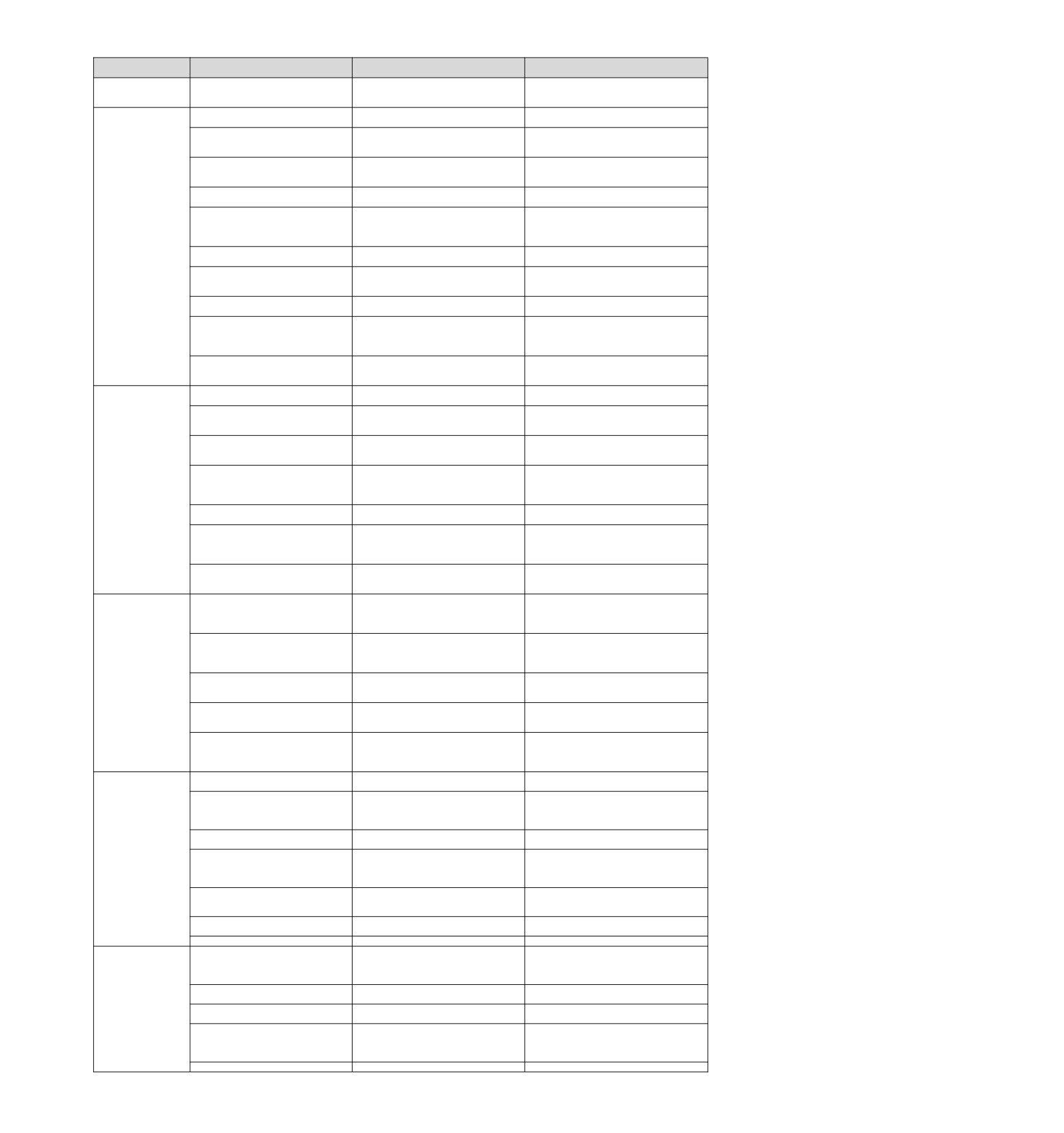
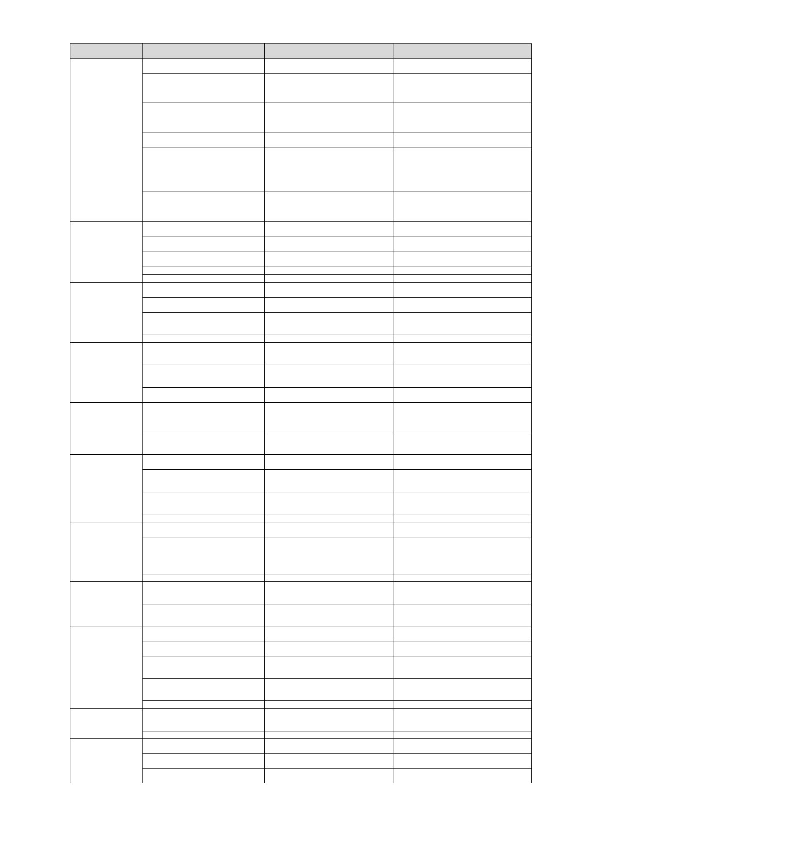
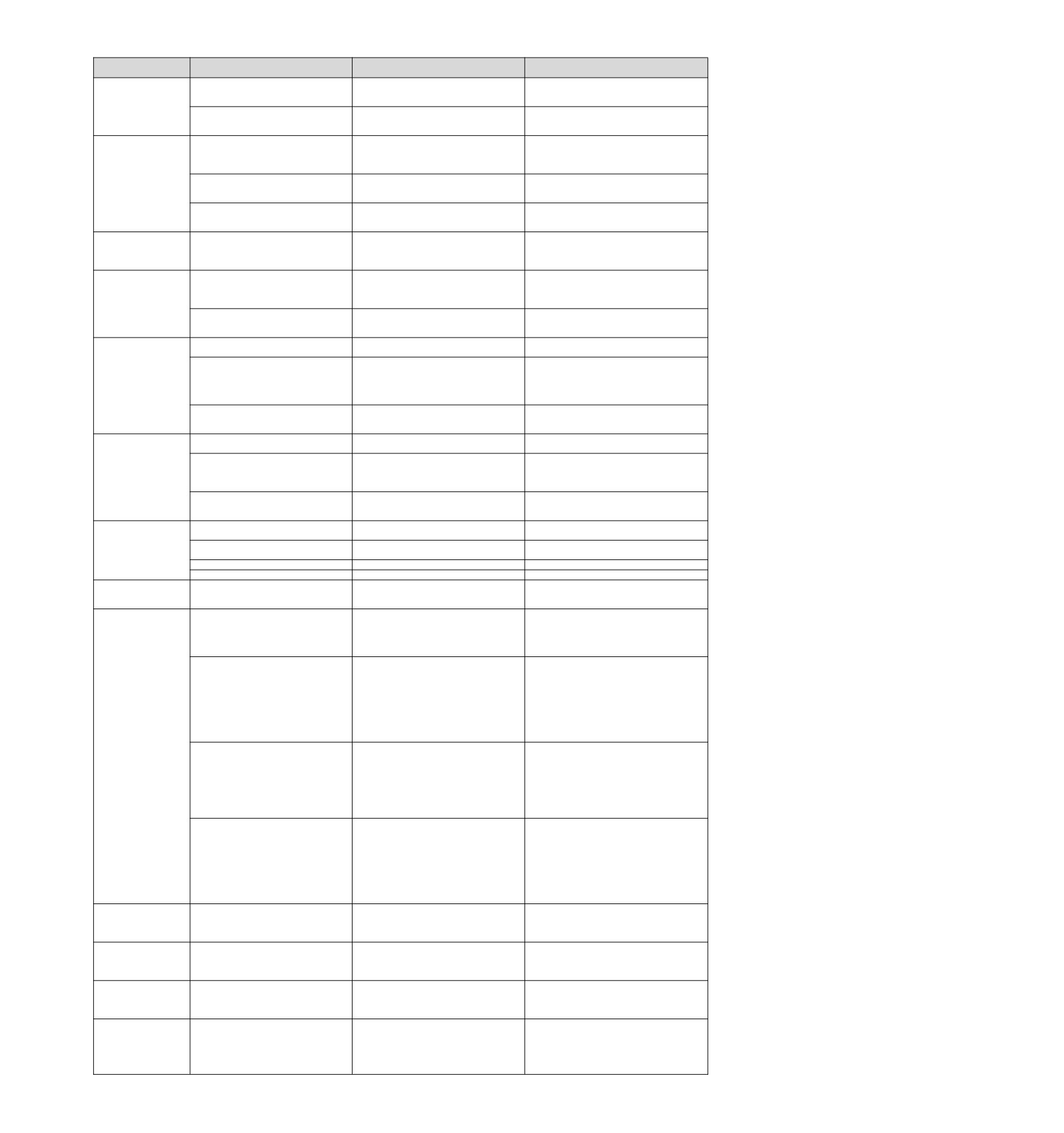
The following table lists the cause of the alarm and the treatment measures. If the fault cannot be cleared after
processing according to the following table, please contact our agency or the nearest branch.
Alarm number:
Reason
Confirmation method
The treatment measures
Alarm name
Set the power supply voltage within the
The
supply
voltage
drops
Measure the supply voltage.
specification range, and perform initialization
instantaneously.
of the parameter setting value.
Re-enter parameters after initialization of
Power off when writing parameters
Confirm the time of power failure.
parameter settings.
A.020:
The number of writes to the parameter
Confirm whether parameter changes are
Replace the servo drive. Change the
Parameter and check
exceeded the maximum
frequently made from the upper device.
parameter writing method.
exceptions
Misoperation occurs due to interference
Connect to the servo drive power supply
The data of internal
from AC power supply, grounding, static
again. When the alarm still occurs, it may
Take measures to prevent mutual interference.
parameters of servo
electricity, etc.
be disturbed.
drive is abnormal.
Due to gas, water droplets or cutting oil,
etc., the components inside the servo
Confirm the setting environment.
Replace the servo drive.
drive have failed.
Connect to the servo drive power supply
Servo drive failure
again. When the alarm still occurs, it may
Replace the servo drive.
be a fault.
A.021:
The software version of the write
Read the product information and confirm
Write the parameters of other servo drives
Parameter
format
parameter is updated as compared to
whether the software versions are the
with the same software version and model,
exception
the software version of the servo drive
same. If the versions are different, an alarm
and then switch on the power supply.
(The data of internal
where the alarm occurred.
may occur.
parameters of servo
Servo drive failure
-
Replace the servo drive.
drive is abnormal.)
The
supply
voltage
drops
A.022:
Measure the power supply voltage
Replace the servo drive.
instantaneously.
System parameters and
The power supply was turned off in the
check exceptions
Confirm the time of power failure.
Replace the servo drive.
process of setting the auxiliary function.
(The data of internal
Connect to the servo drive power supply
parameters of servo
Servo drive failure
again. When the alarm still occurs, it may
Replace the servo drive.
drive is abnormal)
be a fault.
A.030:
Main circuit detection
Servo drive failure
-
Replace the servo drive.
unit failure
Confirm the capacity of servo drive and
Servo capacity does not match servo
Capacity of servo drive and servo motor
servo motor
motor capacity
Match each other.
A.040:
Quantity and combination.
Parameter
setting
Servo drive failure
-
Replace the servo drive.
exception
Confirm the setting range of the changed
Set the changed parameters to values within
Outside the parameter setting range
(beyond the set range)
parameters.
the set range.
The electronic gear ratio setting value is
Verify that the electronic gear ratio is
Set the electronic gear ratio to
outside the set range
0.001<(Pn20E/Pn210)< 64000.
0.001< (Pn20E/Pn210) < 64000.
Since the electronic gear ratio (Pn20E
/Pn210) or servo motor is changed, the
Confirm whether the detection condition
Reduce the value of the electronic gear ratio
running speed of the program JOG does
formula*1 is true.
(Pn20E/Pn210).
not conform to the set range.
Since the program JOG moving speed
A.042:
(Pn533) has been changed, the running
Confirm whether the detection condition
Increase the value of Pn533.
Parameter combination
speed of the program JOG does not
formula*1 is true.
exception
conform to the set range.
Due to the change of electronic gear
ratio (Pn20E/Pn210) or servo motor, the
Confirm whether the detection condition
Reduce the value of the electronic gear ratio
moving speed of advanced automatic
formula*2 is true.
(Pn20E/Pn210).
adjustment does not conform to the set
range.
A.050:
Servo drive capacity does not match
Capacity of servo drive and servo motor
Confirm1≤≤Motorcapacity
4
Combination error
servo motor capacity
4
Servo drive capacity
Match each other.
(outside the combinable
Servo drive failure
-
Replace the servo drive.
motor capacity range)
A.051:
The motor parameter file is not written
Verify that the motor parameter file is
Write the motor parameter file into the
The product does not
into the encoder
(only when serial
written into the encoder.
encoder.
support Alarms
conversion unit is not used)
71
Alarm number:
Reason
Confirmation method
The treatment measures
Alarm name
A.0b0:
After performing the auxiliary function of
Connect to the servo drive power supply
Servo ON command is
energizing the motor, servo is sent from
-
again. Or perform a software reset.
invalid alarm
the upper device ON(SV_ON) command
The main loop cable is incorrectly wired
Verify that the wiring is correct.
Modify the wiring.
or has poor contact.
Verify that there is a short circuit between
Internal short circuit of main loop cable or
The cable may be short-circuited. Replace the
UVW phases of the cable and between
short circuit to ground occurred.
cable.
UVW and ground.
Verify that there is a short circuit between
Short circuit or short circuit to ground
It is possible that the servo motor is faulty.
UVW phases of the motor terminals and
occurs inside servo motor
Replace the servo motor.
between UVW and ground.
Incorrect wiring or poor contact of
Verify that the wiring is correct.
Modify the wiring.
regenerative resistor
Use frequency of DB is confirmed by power
The dynamic brake (emergency stop due
Change the type selection, operation method
A.100:
consumption of DB resistor. Or use alarm
to DB and servo drive) is used frequently
and mechanism of servo drive to reduce the
Overcurrent detection
display to confirm whether DB overload
or DB overload alarm occurs.
use frequency of DB.
(overcurrent flows
alarm has occurred (A.730 or A.731).
through the power
Regenerative resistance value is too
Confirm the frequency of use of the
Discuss the operating conditions and loads
transistor or heat sink to
high
regenerative resistor.
again.
overheat)
The regenerative resistance value is changed
The regenerative resistance value of
Confirm the frequency of use of the
to a value above the minimum allowable
servo drive is too small
regenerative resistor.
resistance value for servo drive.
When the servo motor stops or runs at
Verify that the operating conditions are
Reduce the load borne by the servo motor. Or
low speed, it bears high load
outside the specifications of the servo drive.
at a higher operating speed.
Take measures to prevent interference, such
Improve the interference environment such
as correctly wiring FG. In addition, the wire
Misoperation due to interference
as wiring and confirm whether there is any
size of FG should be the same as that of servo
effect.
drive main loop.
Connect to the servo drive power supply
Servo drive failure
-
again. When an alarm still occurs, replace the
servo drive.
The main loop cable is incorrectly wired
Verify that the wiring is correct
Modify the wiring.
or has poor contact
Verify that there is a short circuit between
Internal short circuit of main loop cable or
The cable may be short-circuited. Replace the
UVW phases of the cable and between
short circuit to ground occurred
cable.
UVW and ground.
Verify that there is a short circuit between
Short circuit or short circuit to ground
It is possible that the servo motor is faulty.
UVW phases of the motor terminals and
occurs inside servo motor
Replace the servo motor.
A.101:
between UVW and ground.
Motor overcurrent
Verify that there is a short circuit between
detection
Short circuit or short circuit to ground
UVW phases and between UVW and
Replace the servo drive.
(The motor flows
occurred inside servo drive
ground at the servo motor connection
through excess
terminal of servo drive.
capacity
When the servo motor stops or runs at
Verify that the operating conditions are
Reduce the load borne by the servo motor. Or
Allowable current)
low speed, it bears high load
outside the specifications of the servo drive.
at a higher operating speed.
Take anti-interference measures, such as
Improve the noise environment such as
correctly wiring FG, etc. In addition, the wire
Misoperation due to noise
wiring and setting, and confirm whether
size of FG should be the same as that of servo
there is any effect.
drive main loop.
Connect to the servo drive power supply
Servo drive failure
-
again. When an alarm still occurs, replace the
servo drive
The regenerative resistance capacity
Confirm the connection of external
Connect external regenerative resistor or set
(Pn600) is set to a value other than "0",
regenerative resistor and the value of
Pn600 (regenerative resistor capacity) to
0
and no regenerative resistance is
Pn600.
when regenerative resistor is not needed.
installed
Set the appropriate value for Pn600
after
Confirm external regenerative resistor or
connecting the external regenerative resistor,
No external regenerative resistance
regenerative power resistance device
or set Pn600
to
0
after connecting the
connection and Pn600 value.
regenerative resistor device.
A.300:
The jumper wire of the regenerative
Confirm the wiring of the power terminal
Regenerative faults
resistor connection terminal B2-B3 falls
Correct wiring of jumper wires.
jumper.
off
Poor connection, falling off or
Confirm the wiring of the external
Correct wiring of external regenerative
disconnection of external regenerative
regeneration resistor.
resistor.
resistor
In the state that the main loop power supply is
not turned on, the servo drive control power
Servo drive failure
-
supply is turned on again. When an alarm still
occurs, replace the servo drive.
Power supply voltage
exceeds
Set the power supply voltage within the
Measure the supply voltage.
specification range
specification.
External regenerative resistance value or
Change the regenerative resistance value and
regenerative resistance capacity is
Reconfirm operating conditions and
regenerative resistance capacity. Adjust the
insufficient or in continuous regenerative
capacity.
operating conditions again.
state
Continuously bears negative load and is
Confirm the load applied to the running
Discuss the system including servo,
in continuous regeneration state
servo motor.
mechanical and operating conditions again.
A.320:
The capacity set in Pn600 (regenerative
Regeneration overload
resistance capacity) is smaller than the
Confirm the connection of regenerative
Correct the Pn600 setting.
capacity of external regenerative
resistor and the value of Pn600.
resistance
The value set in Pn603
(regenerative
Confirm the connection of regenerative
resistance value) is smaller than the
Correct the Pn603 setting.
resistor and the value of Pn603.
external regenerative resistance value
Excessive
external
regenerative
Verify that the regenerative resistance
Change it to the correct resistance value and
resistance
value is correct.
capacity
Servo drive failure
-
Replace the servo drive.
Replace the servo drive when using the
The power supply voltage inside the
Measure the resistance value of the
regenerative resistor built into the servo drive.
servo drive is too high, and the
regenerative resistor with a measuring
When using an external regenerative resistor,
regenerative resistor is disconnected.
instrument.
replace the regenerative resistor.
A.330:
When setting AC power input, DC power
Make the set value of the power supply
Main circuit power
Verify that the power supply is DC.
is input
consistent with the power supply used.
supply wiring error
When setting DC power input, AC power
Make the set value of the power supply
(detected when main
Verify that the power supply is AC.
is input
consistent with the power supply used.
circuit power is turned
The regenerative resistance capacity
on)
Confirm the connection of external
Connect an external regenerative resistor or
(Pn600) is set to a value other than "0"
regenerative resistor and the value of
set Pn600 to 0 when no external regenerative
and no regenerative resistance is
Pn600.
resistor is required.
installed
Servo drive failure
-
Replace the servo drive.
72
Alarm number:
Reason
Confirmation method
The treatment measures
Alarm name
Power supply voltage
exceeds
Adjust the AC/DC power supply voltage to the
Measure the supply voltage.
specification range
product specifications.
Improve the power supply condition and
The power supply is in an unstable state
switch on the servo drive power again after
Measure the supply voltage.
or is affected by lightning strike
installing surge suppressor. When an alarm
still occurs, replace the servo drive.
When the AC power supply voltage
exceeds the specification range,
Confirm the power supply voltage, speed
Adjust the AC power supply voltage to the
acceleration and deceleration are carried
and torque in operation.
product specifications.
A.400:
out
Overvoltage
External regenerative resistance value is
Confirm the operating conditions and
Confirm that the rotational inertia ratio or mass
(Overvoltage Detected
larger than operating conditions
regenerative resistance value.
ratio is within the allowable range.
by Main Circuit Power
Operate in a state where the allowable
Supply in Servo Drive)
moment of inertia ratio or mass ratio is
above the allowable moment of inertia
Confirm that the rotational inertia ratio or
Extend deceleration time or reduce load.
ratio or mass ratio to confirm that the
mass ratio is within the allowable range.
moment of inertia ratio or mass ratio is
within the tolerance
In the state that the main loop power supply is
not turned on, the servo drive control power
Servo drive failure
-
supply is turned on again. When an alarm still
occurs, replace the servo drive.
Adjust the power supply voltage to the normal
Supply voltage below specification
Measure the power supply voltage.
A.410:
range
Under voltage
Power supply voltage drops during
Measure the power supply voltage.
Increase power supply capacity.
(The power supply part
operation
of the main loop inside
If the instantaneous stop holding time (Pn509)
Instantaneous power failure occurred
Measure the power supply voltage.
the servo drive detects
is changed, it is set to a smaller value.
the undervoltage)
Servo drive fuse blown
-
Replace the servo drive
Servo drive failure
-
Replace the servo drive.
U, V, W phase sequence error of motor
Confirm whether there is any problem with the
Confirm the connection of servo motor.
wiring
motor wiring.
A.510:
The command input value exceeds the
Confirm the input command.
Lower the command value. Or adjust the gain.
Over speed
overspeed value
(Motor speed is above
Reduce the speed command input gain and
The motor speed exceeds the maximum
the highest speed)
Confirm the waveform of motor speed.
adjust the servo gain. Or adjust operating
speed
conditions.
Servo drive failure
-
Replace the servo drive.
Confirm the abnormal sound of the motor
Abnormal vibration of motor speed is
Reduce motor speed. Or reduce the speed
and the speed and torque waveforms
detected
loop gain (Pn100).
during operation.
A.520:
The value of the moment of inertia ratio
Confirm the moment of inertia ratio or mass
Correctly set the moment of inertia ratio
Vibration alarm
(Pn103) is larger than the actual value or
ratio.
(Pn103).
varies greatly
Vibration detection value
(Pn312) is
Verify that the vibration detection value
Set the vibration detection value appropriately
inappropriate
(Pn312) is appropriate.
(Pn312).
A.521:
Reduce the load below the allowable moment
Automatically
adjust
The motor vibrates greatly when using
of inertia ratio, or increase the load value set
Confirm the waveform of motor speed.
alarm
the adjustment-free function
by the adjustment-free value to reduce the
(Custom adjustments,
rigidity value.
EasyFFT,
no
The processing method described in the
The motor vibrates greatly when custom
adjustment
Vibration
Confirm the waveform of motor speed.
operation steps for implementing each
adjustment and EasyFFT are performed.
detected in function)
function.
Motor wiring, encoder wiring or poor
Confirm whether there is any problem with
Confirm wiring.
A.710:
connection
motor wiring and encoder wiring.
Overload
Discuss load conditions and operating
The operation of the motor exceeds the
Confirm the overload characteristics and
(instantaneous
conditions again. Or reconsider the motor
overload protection characteristic
operation commands of the motor.
maximum load)
capacity.
A.720:
The motor is not driven due to
Confirm the operation command and motor
Overload
(continuous
mechanical factors,
resulting
in
Improve mechanical factors.
speed.
maximum load)
excessive load during operation
Servo drive failure
-
Replace the servo drive.
The motor is being driven by external
A.730:
Confirm operation status.
Do not drive the motor by external force.
force
A.731:
Try the following measures.
DB overload
The rotating or operating energy when
• Reduce the command speed of servo motor.
(Excessive
power
The usage frequency of DB is confirmed by
DB stops exceeds the capacity of DB
• Reduce the rotational inertia ratio or mass
consumption
of
the power consumption of DB resistor.
resistor
ratio.
dynamic
brake
• Reduce the number of DB stops.
detected)
Servo drive failure
-
Replace the servo drive.
A.740: Impulse Current
The allowable number of inrush current
Lower the ON/OFF frequency of the main loop
Limiting
Resistance
limiting resistors when the main loop
-
power supply.
Overload
power supply is ON/OFF is exceeded
(The main circuit power
on frequency is too
Servo drive failure
-
Replace the servo drive.
high)
Turn on the power supply of absolute
Confirm whether the power is switched on
Setting operation of encoder is carried out
value encoder for the first time
for the first time.
A.810:
The encoder cable was removed and
Confirm whether the power is switched on
Confirm the connection of the encoder and set
Encoder backup alarm
then connected
for the first time.
the encoder.
(only detected when
The servo drive control power supply
After power supply to the encoder is restored
Verify that the encoder connector battery
absolute value encoder
(+5V) and battery power supply have
(battery replacement, etc.), the encoder is set
and connector status are correct.
is connected
both failed
up.
(Detected on encoder
When the alarm cannot be released even if
side
Absolute value coder fault
-
the setting operation is performed again,
replace the servo motor.
Servo drive failure
-
Replace the servo drive.
A.820:
Reset encoder. When it still occurs frequently,
Encoder and check
Encoder failure
-
it is possible that the servo motor fails.
alarm
(Detected on
Replace the servo motor.
encoder side)
Servo drive failure
-
Replace the servo drive.
A.830:
The battery is not well connected and not
Confirm battery connection.
Connect the battery correctly.
Encoder battery alarm
connected
(The absolute value
The battery voltage is lower than the
Measure the battery voltage.
Replace the battery.
encoder battery voltage
specified value (2.7 V)
is below the specified
Servo drive failure
-
Replace the servo drive.
value)
73
Alarm number:
Reason
Confirmation method
The treatment measures
Alarm name
Connect to the servo drive power supply
A.840:
Encoder malfunction
-
again. When an alarm still occurs, replace the
Encoder data alarm
servo motor or encoder.
(Detected on encoder
Correct wiring of encoder periphery
Incorrect operation of encoder due to
side)
-
(separating encoder cable from servo motor
interference, etc
main loop cable, grounding treatment, etc.).
When the control power supply is turned
Confirm the motor speed when the power
Adjust the rotation speed of servo motor to
on, the motor rotates at a speed of 200
A.850:
supply is turned on through the motor
less than 200min-1, and then switch on the
min-1 or more (when rotating the servo
Encoder overspeed
rotation speed.
control power supply.
motor)
(detected when the
Connect to the servo drive power supply
control power is turned
Encoder failure
-
again. When an alarm still occurs, replace the
on)
servo motor or encoder.
(Detected on encoder
Connect to the servo drive power supply
side)
Servo drive failure
-
again. When an alarm still occurs, replace the
servo drive.
A.b6A:
Connect to the servo drive power supply
MECHATROLINK
Servo
drive
MECHATROLINK
-
again. When an alarm still occurs, replace the
Communication ASIC
communication failure
servo drive.
fault 1
Take the following anti-interference measures.
Due to interference, MECHATROLINK
Correct the connection of communication
A.b6b:
-
communication caused misoperation.
cable or FG.
MECHATROLINK
Install ferrite cores on communication cables.
Communication ASIC
Connect to the servo drive power supply
fault 2
Servo
drive
MECHATROLINK
-
again. When an alarm still occurs, replace the
communication failure
servo drive.
U, V, W phase sequence error of motor
Confirm whether there is any problem with the
Confirm the wiring of motor.
wiring
motor wiring.
Whether there is no problem with the wiring of
A.C10:
the motor, if the alarm still occurs after the
Out of control detection
Encoder failure
-
power is switched on again, it may be the fault
(detected when servo is
of the servo motor or encoder. Replace the
ON)
servo motor or encoder.
Connect to the servo drive power supply
Servo drive failure
-
again. When an alarm still occurs, replace the
servo drive.
Confirm the voltage of the linear encoder
Installation of reading head of fine grating
Linear encoder signal level low
signal
ruler. Or replace the linear encoder.
Confirm the setting of Pn080=n. X
The positive counting direction of the
Change
the
setting
of
(motor phase sequence selection) and the
A.C20:
linear encoder does not match the
Pn080=n.X.Reinstall the linear encoder
installation direction of linear encoder and
Phase error detection
positive direction of the motor rotor
and motor rotor.
motor rotor.
Correct FG wiring. Implement anti-interference
The magnetic pole sensor signal is
-
countermeasures for magnetic pole sensor
disturbed
wiring.
Linear encoder grating scale pitch
Confirm linear encoder grating pitch
Confirm the specifications of linear encoder
(Pn282) setting error
(Pn282).
and set the value correctly.
A.C21:
The magnetic pole sensor is exposed
Magnetic pole sensor
Confirm magnetic pole sensor.
Reinstall the motor rotor or stator.
outside the motor stator
failure
Incorrect wiring of magnetic pole sensor
Confirm the wiring of magnetic pole sensor.
Correct the wiring of magnetic pole sensor.
Magnetic pole sensor failure
-
Replace the magnetic pole sensor.
A.C22:
Servo unit and linear encoder
Phase information is
-
Perform magnetic pole detection.
Phase information is different
inconsistent
The settings of linear encoder grating pitch
Confirm the specifications of the linear
(Pn282) and motor phase sequence selection
Parameter setting incorrect
encoder and the status of the feedback
(Pn080 = n. X ) may not be consistent
signal.
with the state of the device.Set parameters
correctly.
Confirm that the serial conversion unit, FG
of servo motor and FG of servo unit are
connected, and FG of servo unit is
connected with FG of power supply. In
Take appropriate anti-interference measures
The grating scale signal is disturbed
addition, it is confirmed that the cable of the
for cables used for linear encoders.
linear encoder is indeed shielded. Confirm
whether the detection command is
repeatedly output in the same direction for
many times.
A.C50:
Even if the detection command is 0 and the
Magnetic pole detection
speed feedback is not 0 when external force
failed
such as cable tension is applied to the motor
The motor rotor is subjected to external
rotor, and it cannot be detected smoothly.
-
force
Reduce the external force so that the speed
feedback is
0. Increase the magnetic pole
detection speed loop gain (Pn481) when the
external force cannot be reduced.
When the pitch of linear encoder grating scale
is more than
100m, the servo unit cannot
detect the correct speed feedback. Use high
precision linear encoder grating scale pitch
Confirm whether the pitch of linear encoder
Linear encoders have low resolution
(within 40m is recommended). Or increase the
grating ruler is within 100 m.
magnetic pole detection command speed
(Pn485). However, the motor operation range
when magnetic poles are detected becomes
larger.
A.C51:
Connect the over-travel signal. Magnetic pole
Over-travel
detection
Over-travel signal is detected when
Confirm the overtravel position.
detection is carried out at the position where
when magnetic pole is
magnetic pole is detected
the over-travel signal cannot be detected.
detected
Servo ON in the following states
A.C52:
• When magnetic pole detection is not
Magnetic pole detection
-
Input /P-DET signal.
completed
is not complete
• When/p-det is not entered
A.C53:
The detection moving distance exceeds
Expand the range of magnetic pole detection
The magnetic pole
the magnetic pole detection moving
-
activities
(Pn48E). Or increase the pole
detection is beyond the
range.(Pn48E)
detection speed loop gain (Pn481).
active range
Increase the value of the magnetic pole
detection confirmation thrust command
A.C54:
(Pn495). Increase the allowable range of
Magnetic pole detection
Under external force
-
magnetic pole detection error
(Pn498).
failed 2
However, once the error tolerance range is
expanded, the motor temperature will rise.
74