WT9 Dynamic LSA. AIRCRAFT MAINTENANCE MANUAL (AS-AMM-01-000, 22. 05. 2017) - page 46
 

  Index      Manuals     WT9 Dynamic LSA. AIRCRAFT MAINTENANCE MANUAL (AS-AMM-01-000, 22. 05. 2017)


Search            copyright infringement  


Content      ..     44      45      46      47     ..


WT9 Dynamic LSA. AIRCRAFT MAINTENANCE MANUAL (AS-AMM-01-000, 22. 05. 2017) - page 46


TOWING EQUIPMENT 


OPTIONAL EQUIPMENT 

95-10  TOWING EQUIPMENT 

1.  DESCRIPTION 

Aircraft  without  towing  equipment  is  prepared  for  future  installation  of  tow  release 
mechanism in the aft section of fuselage under the rudder. Until the towing equipment 
is not installed, the tow release mechanism holder has blended holes for bolts and tow 
release mechanism. 

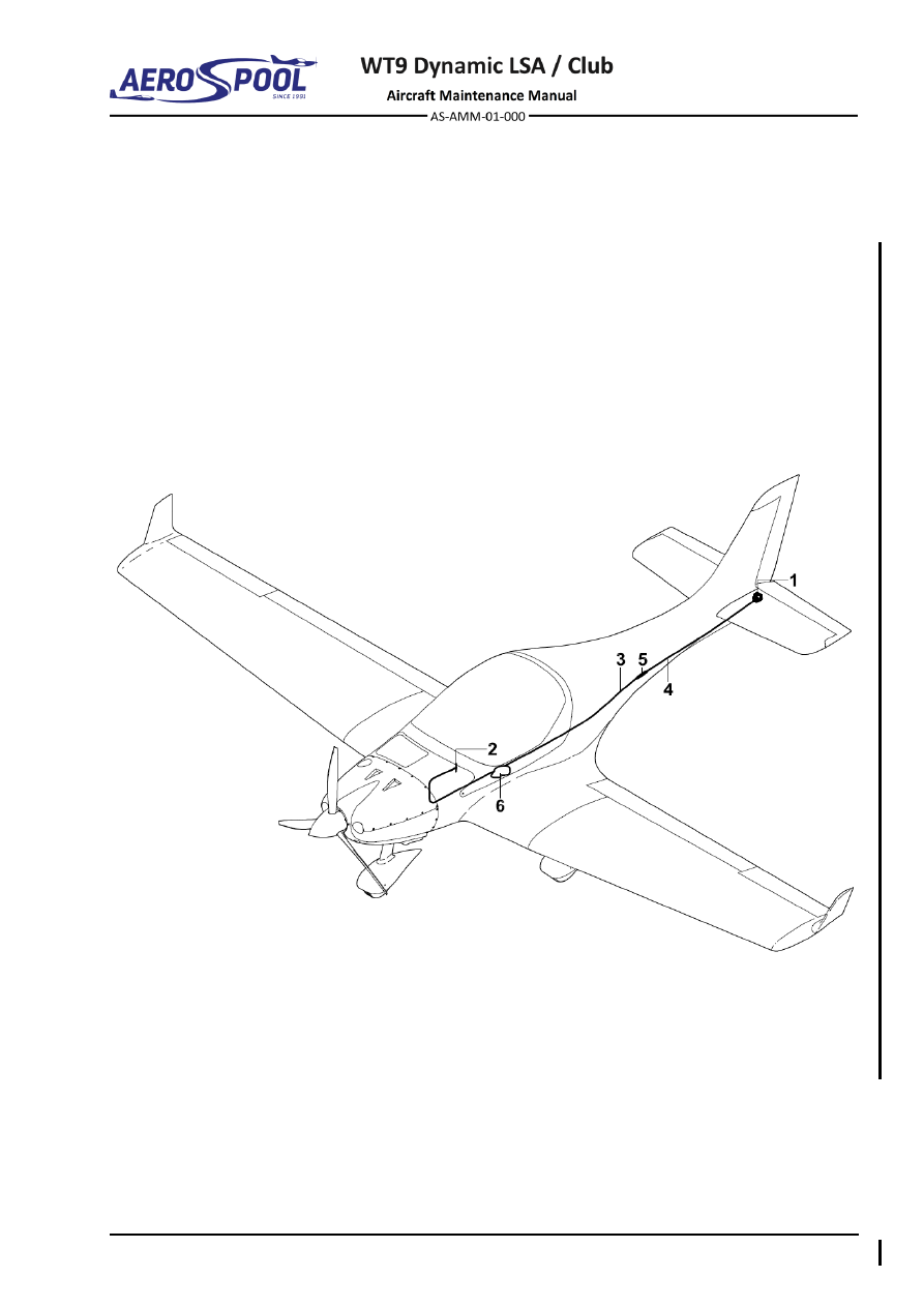
Aircraft  with  towing  equipment  has  installed  tow  release  mechanism  (1,  Fig.  95-1).  
It is operated by a tow release handle (2) installed on the left side of central tunnel. 
Tow  release  handle  is  connected  with  the  tow  release  mechanism  by  steel  ropes  
(3, 4) that are connected by means of turnbuckle (5). Rear-view mirror (6) is installed 
on the left side of canopy frame. 


–  Tow release mechanism and rear-view camera  5 –  Turnbuckle 

–  Tow release handle 

–  Steel rope 

–  Steel rope 

–  Rear-view mirror 

Fig.  95-1  Towing Equipment Installation 


Effectivity:

 ALL 

04. 07. 2019


OPTIONAL EQUIPMENT 

2.  MAINTENANCE PRACTICES 

A. 

Towing equipment preparation 

NOTE 

Towing equipment preparation is used for that aircraft in which the towing 
equipment is not installed. 

Type of maintenance: 

Line 

Personnel qualification: 

Independent certifying staff qualified in accordance 


with Part-66 or higher. 

Recommended tools, materials, persons and documentation: 

ITEM 

QUANTITY 

Wrench 10 

1 pc 

Socket 10 

1 pc 

Phillips screwdriver 

1 pc 

Persons 

Tab. 95-1 Recommended tools, materials, persons and documentation 

(1)  Towing equipment preparation removal: 

(a)  Remove the covering sticker (7, Fig. 95-2). 

(b)  Remove the nuts (6), washers (5), tubes (1), bolts (3) from the 

fuselage. 

(c)  Remove the bolts (4) and protective plate (2). 

(2)  Towing equipment preparation installation: 

(a)  Mount the protective plate (2, Fig. 95-2) using bolts (4) to the 

fuselage. 

(b)  Mount the bolts (3), tubes (1), washers (5) and nuts (6) to the 

fuselage. 

(c)  Apply covering sticker (7). 


TOWING EQUIPMENT 


OPTIONAL EQUIPMENT 


–  Distance tube 

–  Washer ø6 x 12 x 0.5 

–  Protective plate 

–  Nut M6 Flat 

–  Bolt M6 x 50 

–  Sticker 

–  Screw M3 x 10 


Fig.  95-2  Towing Equipment Preparation Removal / Installation 


Effectivity:

 ALL 

04. 07. 2019


OPTIONAL EQUIPMENT 

B. 

Tow release handle 

Type of maintenance: 

Line 

Personnel qualification: 

Independent certifying staff qualified in accordance 


with Part-66 or higher. 

Recommended tools, materials, persons and documentation 

ITEM 

QUANTITY 

Wrench 9 

1 pc 

Wrench 10 

2 pcs 

Combination pliers 

1 pc 

Nicopress tool 

1 pc 

Vaseline 

AR 

Persons 

Tab. 95-2 Recommended tools, materials, persons and documentation 

(1)  Tow release handle removal: 

(a)  Release the front control cable (6, Fig. 95-3) by removing the nut (4), 

washers (2, 3), distance tube (5) and bolt (1). 

(b)  Release the short control cable (11) by removing the nut (4), washers 

(2, 3, 10), distance tubes (8, 9) and bolt (7). 

(c)  Remove the nuts (4), washers (10), ground wire (14), levers (15 and 

19), bolts (12) and remove the tow release handle (13) from  
the central tunnel left side; cut short control cable (11) and pull it out. 

(d)  Disassemble the levers assembly (15, 19) by removing cotter pin 

(18), nut (17), washers (2, 3) and bolt (16). 

(2)  Tow release handle installation: 

(a)  Make an eye on one end of new control cables (6, 11, Fig. 95-3) 

according to 2.C.(2)(c). 

NOTE 

Lubricate steel control cables with vaseline on entire length. 

(b)  Assemble the control handle console (13) with handle (20), washer 

(21), sleeve (22) and short control cable (11) before the installation  
to the aircraft. Press the sleeve with Nicopress tool at 3 points. 

NOTE 

At fully opened tow release there must be a 5 mm reserve prior 
to end position of short control cable. 

(c)  Assemble the levers (15, 19) with the bolt (16), washers (2, 3), nut 

(17), and secure with cotter pin (18) before the installation to the 
aircraft. 


TOWING EQUIPMENT 


OPTIONAL EQUIPMENT 

(d)  Slide free end of front control cable (6) through a plastic tube  

to the aft section of fuselage. 

NOTE 

Plastic tube is located in central tunnel. 

(e)  Install the assembled levers (15, 19) with control handle console (13) 

on the central tunnel left side using bolts (12), ground wire (14), 
washers (10) and nuts (4). 

(f) 

Connect the short control cable (11) to lever 2 (19) using bolt (7), 
distance tubes (8, 9), washers (2, 3, 10) and nut (4). 

(g)  Connect the front control cable (6) to lever 2 (19) using bolt (1), 

distance tube (5), washers (2, 3) and nut (4). 


Effectivity:

 ALL 

04. 07. 2019


OPTIONAL EQUIPMENT 


–  Bolt M6 x 22 

12 

–  Bolt M6 x 25 

–  Washer ø6 x 18 x 1.6 

13 

–  Control handle console 

–  Washer ø6 x 12 x 0.5 

14 

–  Ground wire 

–  Self-locking nut M6 

15 

–  Lever 1 

–  Distance tube 8 x 1 

16 

–  Bolt M6 x 22 

–  Front control cable 

17 

–  Castle nut M6 

–  Bolt M6 x 32 

18 

–  Cotter pin ø1.6 x 12 

–  Distance tube 10 x 1 

19 

–  Lever 2 

–  Distance tube 

20 

–  Handle 

10 

–  Washer ø6 x 12 x 1.6 

21 

–  Washer ø4 x 12 x 1 

11 

–  Short control cable 

22 

–  Sleeve 2.4 - 2.6 

Fig.  95-3  Tow Release Handle Removal / Installation 


TOWING EQUIPMENT 


OPTIONAL EQUIPMENT 

C. 

Tow release equipment 

Type of maintenance: 

Line 

Personnel qualification: 

Independent certifying staff qualified in accordance 


with Part-66 or higher. 

Recommended tools, materials, persons and documentation 

ITEM 

QUANTITY 

Wrench 8 

1 pc 

Socket 10 

1 pc 

Pliers 

1 pc 

Screwdriver 

1 pc 

Steel wire cutter 

1 pc 

Nicopress tool 

1 pc 

Lockwire ø0.8 mm 

AR 

Vaseline 

AR 

Persons 

Tab. 95-3 Recommended tools, materials, persons and documentation 

(1)  Tow release mechanism removal: 

(a)  Remove the baggage bulkhead cover (13, Fig. 06-4, Chapter 06). 

(b)  Remove the ground wire (9, Fig. 95-4) by removing the nuts (11), 

washers (12), clamps (13) and bolts (10). 

(c)  Remove the lockwire (1) from turnbuckle (2) and release the 

turnbuckle. 

(d)  Remove the nuts (4), washers (5), bolts (3) and distance tubes (6) 

from turnbuckle (2) to release the control cables (7, 8). 

(e)  Disconnect the camera wire (25) from the voltage converter (26) 

(f) 

Remove the nuts (16), washers (17), bolts (14, 15), rear-view camera 
(19) and tow release mechanism (20). 

(g)  Remove the nut (4), washer (5), spacer (21) and bolt (3) from tow 

release mechanism lever (20) to release the rear control cable (8). 

(2)  Tow release mechanism installation: 

(a)  Check condition of the tow release mechanism and control cables. 

(b)  Install the front control cable (7, Fig. 95-4) to fuselage (see 2.B.(2)). 

(c)  Make an eye on the end of front control cable (7) with thimble (22), 

sleeve (23). Press sleeve (23) closely to thimble with Nicopress tool 
at 3 points. Cut unnecessary end of steel cable. 

(d)  Make an eye on end of rear control cable (8) with thimble (22), 

sleeve (23). Press sleeve (23) closely to thimble with Nicopress tool 
at 3 points. Cut unnecessary end of steel cable. 

(e)  Lubricate entire length of rear control cable (8) with vaseline. 


Effectivity:

 ALL 

04. 07. 2019


OPTIONAL EQUIPMENT 

(f) 

Slide free end of rear control cable (8) through plastic tube to 
fuselage from the rear. 

NOTE 

Plastic tube is located in the aft section of fuselage. 

(g)  Connect the rear control cable to the tow release mechanism (20) 

using bolt (3), spacer (21) washer (5) and nut (4). 

(h)  Put the tow release mechanism (20) into the fuselage, slip the 

camera

’s wiring into installation tube in the rear section of fuselage, 

place the rear-view camera (19) to correct position and attach the 
tow release mechanism and rear-view camera using bolts (14, 15), 
washers (17), spacers (18) and nuts (16). 

(i) 

Connect the camera wires (25) to voltage converter (26) according  
to Aircraft Wiring Manual (Doc. NO. AS-AWM-01-000) 

(j) 

Make an eye on the other end of rear control cable (8) with thimble 
(22), sleeve (23). Press sleeve (23) closely to thimble with Nicopress 
tool at 3 points. Cut unnecessary end of steel cable. 

(k)  Connect the control cables (7, 8) to the turnbuckle (2) using bolts (3), 

distance tubes (6), washers (5) and nuts (4). 

(l) 

Stretch the control cables by turnbuckle (2) to eliminate dead travel, 
but the tow release mechanism cannot start to open. 

NOTE 

Distance the axle of  turnbuckle first bolt must be 320 mm from 
the baggage bulkhead. 

(m)  Lock the turnbuckle (2) by locking wire (1). 

(n)  Install the ground wire on control cables using bolts (10), clamps 

(13), washers (12) and nuts (11). 

(o)  Install the baggage bulkhead cover (13, Fig. 06-4). 

(p)  Carry out test and check: 

  If all bolt connections are tight 

  Plays 

  Tension of control cable (no dead travel) 

  That no foreign objects remain in the aircraft 

  5 mm reserve of short control cable of tow release handle at fully 

opened tow release mechanism 

  Check if tow release mechanism is fully closed when the control 

handle is released 

  Operation of tow release mechanism 


TOWING EQUIPMENT 


OPTIONAL EQUIPMENT 

(3)  Rear-view camera visibility test:  

(a)  Level the aircraft (Chapter 08-10). 

(b)  Place the template (Fig 95-6) behind the aircraft in the required 

position (Fig 95-5). 

(c)  Set the template reference point (1, Fig 95-6) exactly in relation to 

the tow release mechanism center line (3, Fig. 95-5). The template 
must be set in lateral and vertical direction perpendicular to the tow 
release mechanism centerline (3, Fig. 95-5). 

(d)  Display the rear-view camera on RH SV-D1000 and check that entire 

visibility area is displayed. 

NOTE 

The rear-view camera must be set that the entire visibility area is 
displayed  on  RH  SV-D1000.  This  ensure  unrestricted  view  of 
towed glider in the required range. 

(e)  If the visibility area is not fully displayed on the RH SV-D1000, 

screen, release the nuts (16, Fig. 95-4) of bolts (15). Adjust the rear-
view camera position until entire visibility area is displayed on the RH 
SV-D1000. 

(f) 

Check the min. 4 mm gap between the rear-view camera and rudder. 
Tighten the nuts (16) on the bolts (15). 

(g)  After adjusting of rear-view camera check: 

  If all bolt connections are tight. 

  That no foreign objects remain in the aircraft. 

  Gap between the rear-view camera and rudder 

  Rear-view camera visibility check 


Effectivity:

 ALL 

04. 07. 2019


OPTIONAL EQUIPMENT 


Fig.  95-4  Tow Release Mechanism Removal / Installation (page 1 of 2) 


TOWING EQUIPMENT 


OPTIONAL EQUIPMENT 


–  Lockwire 

14 

–  Bolt M6 x 50 

–  Turnbuckle 

15 

–  Bolt M6 x 54 

–  Bolt M5 x 20 

16 

–  Self-locking nut M6 

–  Self-locking nut M5 

17 

–  Washer ø6 x 12 x 0.5 

–  Washer ø5.3 x 10 x 1 

18 

–  N/A 

–  Distance tube 8 x 1 

19 

–  Rear-view camera 

–  Front control cable 

20 

–  Tow release mechanism 

–  Rear control cable 

21 

–  Spacer 

–  Ground wire 

22 

–  Thimble 2.1 - 3.0 

10 

–  Bolt M4 x 10 

23 

–  Sleeve 2.4 - 2.6 

11 

–  Self-locking nut M4 

24 

– Installation tube  

12 

–  Washer ø4 x 12 x 1 

25 

– Camera wire 

13 

–  Clamp 

26 

– Voltage converter 

Fig.  95-4   Tow Release Mechanism Removal / Installation (page 2 of 2) 


Effectivity:

 ALL 

04. 07. 2019


OPTIONAL EQUIPMENT 


–  Camera visibility area 

– 

Tow release mechanism center line 

–  Template 


Fig.  95-5   Rear-View Camera Visibility Test 


TOWING EQUIPMENT 


OPTIONAL EQUIPMENT 


–  Visibility area (template border) 

– 

Reference point 

Fig.  95-6   Camera Visibility Template 


Effectivity:

 ALL 

04. 07. 2019


OPTIONAL EQUIPMENT 

D. 

Rear-view mirror 

Type of maintenance: 

Line 

Personnel qualification: 

Independent certifying staff qualified in accordance 


with Part-66 or higher. 

Recommended tools, materials, persons and documentation 

ITEM 

QUANTITY 

Screwdriver 

1 pc 

Hex key 3 

1 pc 

Loctite 243 

AR 

Persons 

Tab. 95-4 Recommended tools, materials, persons and documentation 

(1)  Rear-view mirror removal: 

(a)  Remove the bolt (5, Fig. 95-7) and pull out the rear-view mirror (1) 

with washer (4). 

(b)  Unscrew the bolts (6) and remove the mirror base (2) with seal (3). 

(2)  Rear-view mirror installation: 

(a)  Install the mirror base (2, Fig. 95-7) and seal (3) on canopy frame; 

apply Loctite 243 on the bolts (6) and attach the base. 

(b)  Put the rear-view mirror (1) with washer (4) to mirror base (2); apply 

Loctite 243 on the bolt (5) and attach the mirror. 


TOWING EQUIPMENT 


OPTIONAL EQUIPMENT 


–  Rear-view mirror 

–  Washer 

–  Mirror base 

–  Bolt M4 x 40 

–  Seal 

–  Bolt M5 x 12 

Fig.  95-7  Rear-View Mirror Removal / Installation 


Effectivity:

 ALL 

04. 07. 2019


OPTIONAL EQUIPMENT 

E. 

Voltage converter 

Type of maintenance: 

Line 

Personnel qualification: 

Independent certifying staff qualified in accordance 


with Part-66 or higher. 

Recommended tools, materials, persons and documentation 

ITEM 

QUANTITY 

Soldering iron 

1 pc 

Flathead screwdriver 

1 pc 

Soldering tin 

AR 

Persons 

Tab. 95-5 Recommended tools, materials, persons and documentation 

(1)  Voltage converter removal: 

(a)  Set 

MASTER SWITCH

 to 

OFF

 position. 

(b)  Remove the baggage bulkhead cover (13, Fig. 06-4, Chapter 06). 

(c)  Cut the cable ties to release the voltage converter (1, Fig. 95-6). 

(d)  Open the voltage converter covering (1). 

(e)  Loose screws on terminal and disconnect the camera wires (2). 

(f) 

Unsolder wires (3) and remove the voltage converter (1). 

(2)  Voltage converter installation: 

(g)  Set 

MASTER SWITCH

 to 

OFF

 position. 

(a)  Before assembling check the condition of wires (2; 3, Fig. 95-6). 

(b)  Solder wires (3) to voltage converter (1) according to Aircraft Wiring 

Manual (Doc. NO. AS-AWM-01-000). 

(c)  Connect the camera wires (2) to the terminal of voltage converter (1) 

according to Aircraft Wiring Manual (Doc. NO. AS-AWM-01-000). 

(d)  Install the cover of voltage converter (1). 

(e)  Attach the voltage converter (1) to the aircraft by means of cable ties. 

(f) 

Install the baggage bulkhead cover (13, Fig. 06-4, Chapter 06). 

(g)  Set 

MASTER SWITCH

 to 

ON

 position and carry out an operational 

test. 


Content      ..     44      45      46      47     ..