WT9 Dynamic LSA. AIRCRAFT MAINTENANCE MANUAL (AS-AMM-01-000, 22. 05. 2017) - page 45
 

  Index      Manuals     WT9 Dynamic LSA. AIRCRAFT MAINTENANCE MANUAL (AS-AMM-01-000, 22. 05. 2017)


Search            copyright infringement  


Content      ..     43      44      45      46     ..


WT9 Dynamic LSA. AIRCRAFT MAINTENANCE MANUAL (AS-AMM-01-000, 22. 05. 2017) - page 45


Effectivity:

 ALL 

04. 07. 2019


EXHAUST 


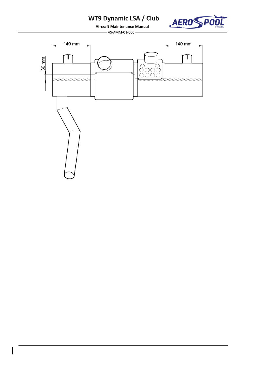
Fig.  78-3  Correctly assembled exchangers 


CONTENTS 


OIL 

79  OIL 

CONTENTS 

GENERAL ......................................................................... 3


1.


INTRODUCTION ....................................................................... 3


2.


TROUBLESHOOTING ............................................................... 4


79-20


OIL SYSTEM ..................................................................... 5


1.


DESCRIPTION .......................................................................... 5


2.


MAINTENANCE PRACTICES ................................................... 6


A.


Oil tank .............................................................................. 6


B.


Oil cooler ........................................................................... 8


C.


Oil thermostat .................................................................. 12


79-30


INDICATING ................................................................... 13


1.


DESCRIPTION ........................................................................ 13


2.


MAINTENANCE PRACTICES ................................................. 14


A.


SV-D1000 display ............................................................ 14


B.


SV-EMS-220 module ....................................................... 14


C.


Low value warning unit .................................................... 14


D.


Oil pressure sensor ......................................................... 14


E.


Oil temperature sensor .................................................... 14


GENERAL 


OIL 

79-00


GENERAL


1.  INTRODUCTION 

The engine Rotax 912 ULS2 has a dry sump forced lubrication system. The oil pump 
(3,  Fig.  79-1)  is  driven  by  means  of  camshaft.  The  oil  accumulates  at  the  bottom  
of  crankcase  and  it  is  forced  back  to  the  oil  tank  (4)  by  energy  of  gassed  
in the crankcase. The oil pump sucks the engine oil from the oil tank, through the oil 
thermostat  (9)  and  oil  filter  (6)  and  ensures  the  engine  lubrication.  In  dependence  
of  temperature,  the  oil  thermostat  opens  the  circuit  of  oil  cooler  (5).  The  oil  tank  is 
equipped with a venting hose (7). 

NOTE 

Refer  to  the  Maintenance  Manual  (Line  Maintenance)  for  Engine  Type  
912 Series, Ref. No.: MML-912 for additional information. 


  Pressure relief valve 

  Oil filter 

  Oil pressure sensor 

  Oil tank venting 

  Oil pump 

  Oil temperature sensor 

  Oil tank 

  Oil thermostat 

  Oil cooler 


Fig. 79-1  Oil System 


Effectivity:

 ALL 

28. 04. 2021


OIL 

2.  TROUBLESHOOTING 


TROUBLE 

POSSIBLE CAUSE 

REMEDY 

High oil temperature 
indication. 

Thermostat damaged or 
held open by solid matter. 

Replace thermostat. 

Oil viscosity too high. 

Drain and refill with 
correct oil grade  
(Chapter 12-00). 

Prolonged ground 
operation. 

Limit ground operation  
to a minimum. 

High power, low airspeed.  Adjust power - flight 

altitude. 

Low oil supply. 

Replenish oil supply. 

Cooler air passages 
clogged. 

Clean cooler thoroughly. 

Malfunctioning sensor. 

Check sensor. Replace  
if required. 

Low oil pressure 
indication. 

Low oil supply. 

Replenish oil supply. 
(Chapter 12-10) 

Oil viscosity too low 

Drain and refill with 
correct oil grade  
(Chapter 12-00). 

Pump producing low 
pressure. 

Replace pump. 

Malfunctioning sensor. 

Check sensor. Replace  
if required. 


OIL SYSTEM 


OIL 

79-20


OIL SYSTEM


1.  DESCRIPTION 

This  chapter  describes  storage  of  oil  and  portion  of  the  oil  system  that  is  used  
to conduct oil from and to the engine. These items include the oil tank, oil cooler and 
oil thermostat. 
Oil  tank  is  attached  at  firewall  on  the  right  side  and  for  oil  level  check  is  available 
through the door on the upper engine cowling. 
Max. oil system capacity:   

Approx. 3.5 liters 

Oil consumption:  


Max. 0.06 l/h 

Maintenance practices and procedures concerning oil volume check/replenishing and 
oil change are mentioned in Chapter 12-10. 

NOTE 

Recommended  oils  are  mentioned  in  the  Rotax  Service  Instruction  
No. SI-912-016 

 the latest issue. 

Oil cooler (5, Fig. 79-1) is attached in the ram air tunnel on the right side of lower engine 
cowling. For oil temperature regulation the oil thermostat (9) is installed. Depending  
on oil temperature oil flows to the oil pump (3) directly or through the oil cooler (5). Oil 
thermostat is installed between the oil tank (4), oil cooler (5) and oil pump (3). 


Effectivity:

 ALL 

28. 04. 2021


OIL 

2.  MAINTENANCE PRACTICES 

A.  Oil tank 

Type of maintenance: 

Line 

Personnel qualification: 

Independent  certifying  staff  qualified  in  accordance 


with Part-66 or higher. 

Recommended tools, materials, persons and documentation:  

ITEM 

QUANTITY 

Wrench 4 

1 pc 

Screwdriver 5 

1 pc 

Pliers 

1 pc 

Oetiker pliers 

1 pc 

Lockwire 

ø

0.8 mm 

AR 

Maintenance Manual (Line Maintenance) for Rotax Engine 
Type 912 Series, Ref. No.: MML-912 

Persons 

Tab. 79-1 Recommended tools, materials, persons and documentation 

WARNING 

ENGINE IGNITION MUST BE SWITCHED OFF. 
CARELESS  DRAINING  OF  HOT  ENGINE  OIL  MAY  CAUSE 
SCALDS.  DISPOSE  OF  USED  OIL  AND  FILTERS  RESPECTING 
THE ENVIRONMENTAL AND SAFETY REGULATIONS. 

(1)  Oil tank removal: 

(a)  Make sure that the 

IGNITION

 switches are set 

OFF

.  

(b)  Remove the engine cowlings (Chapter 71-10). 
(c)  Drain the oil from the oil system (Chapter 12-10). 
(d)  Disconnect hoses (7; 8; 9, Fig. 79-2) from tank (1) by removing safety 

clamps (10; 11). 

(e)  Remove lockwire (6), release universal clamps (2) and remove tank 

(1). 

(f) 

Install protective plugs on the hoses and oil tank elbows. 


OIL SYSTEM 


OIL 


  Oil tank 

  Distance tube 

  Venting hose 

  Universal clamp 

ø

136  6 

  Lockwire 

10 

  Safety clamp 20.7 

  Screw of lock 

  Inlet hose 

11 

  Safety clamp 17.5 

  Nut M4 

  Outlet hose 


Fig. 79-2  Oil Tank Removal / Installation 


Effectivity:

 ALL 

28. 04. 2021


OIL 

(2)  Oil tank installation: 

(a)  Make sure that the 

IGNITION

 switches are set 

OFF

.  

(b)  Put  oil  tank  (1,  Fig.  79-2)  to  the  appropriate  position  in  the  holder  

and secure it with universal clamps (2); secure universal clamps (2) 
with lockwire (6) (see Chapter 20-20). 

(c)  Remove protective plugs from the hoses and oil tank elbows. 
(d)  Slide  hoses  (7;  8;  9)  on  the  appropriate  elbows  on  the  oil  tank  (1); 

secure them with safety clamps (10; 11). 

(e)  Check if hoses are firmly secured and sealed. 
(f) 

Replenish the oil system (Chapter 12-10). 

(g)  Carry out engine ground test; check oil system for leaks and oil system 

indication. 

(h)  Install the engine cowlings (Chapter 71-10). 

B.  Oil cooler 

Type of maintenance: 

Line 

Personnel qualification: 

Independent  certifying  staff  qualified  in  accordance 


with Part-66 or higher. 

Recommended tools, materials, persons and documentation: 

ITEM 

QUANTITY 

Wrench 12 

1 pc 

Wrench 14 

1 pc 

Wrench 18 

1 pc 

Screwdriver 5 

1 pc 

Pliers 

1 pc 

Oetiker pliers 

1 pc 

Lockwire ø0

.8 mm 

AR 

Cooper gasket ring 

ø14

.2 x 20 x 2 

2 pcs 

Maintenance Manual (Line Maintenance) for Rotax Engine 
Type 912 Series, Ref. No.: MML-912 

Persons 

Tab. 79-2 Recommended tools, materials, persons and documentation 

WARNING 

ENGINE IGNITION MUST BE SWITCHED OFF. 
CARELESS  DRAINING  OF  HOT  ENGINE  OIL  MAY  CAUSE 
SCALDS.  DISPOSE  OF  USED  OIL  AND  FILTERS  RESPECTING 
THE ENVIRONMENTAL AND SAFETY REGULATIONS. 


OIL SYSTEM 


OIL 

(1)  Oil cooler removal: 

(a)  Make sure that the 

IGNITION

 switches are set 

OFF

(b)  Remove the engine cowlings (Chapter 71-10). 
(c)  Drain the oil from the oil system (Chapter 12-10). 
(d)  As necessary, disconnect hose (7, Fig. 79-2) from the nipple on the oil 

tank. 

(e)  Disconnect  hoses  (9;  10,  Fig.  79-3)  from  oil  cooler  (1)  by  removing 

safety clamps (14). 

(f) 

Suck oil from oil thermostat (2). 

(g)  Loose nuts (7) and remove the oil cooler (1). 
(h)  As necessary, unscrew and remove elbows (3), reducers (4), gasket 

rings (5), nuts (7) and washers (6). 

(i) 

Install protective plugs on the hoses and oil cooler screw couplings. 

(2)  Oil cooler installation: 

(a)  Make sure that the 

IGNITION

 switches are set 

OFF

.  

(b)  Remove  protective  plugs  from  the  hoses  and  oil  cooler  screw 

couplings. 

(c)  As  necessary,  on  the  oil  cooler  screw  couplings  install  washers  

(6, Fig. 79-3), slightly screw nuts (7), install new gasket rings (5), screw 
and tighten reducers (4) and slightly screw elbows (3).  

(d)  Put oil cooler (1) to the tunnel and tighten nuts (7). 
(e)  Slide  hoses  (9;  10)  on  the  appropriate  elbows  on  the  oil  cooler  (1); 

secure them with safety clamps (14); tighten elbows (3). 

(f) 

Check if hoses are firmly secured and sealed. 

(g)  Replenish the oil system (Chapter 12-10). 
(h)  Carry out engine ground test; check oil system for leaks and oil system 

indication. 

(i) 

Install the engine cowlings (Chapter 71-10). 


Effectivity:

 ALL 

28. 04. 2021


OIL 


Fig. 79-3  Oil Cooler and Thermostat Removal / Installation (page 1 of 2) 


OIL SYSTEM 


OIL 


  Oil cooler 

  Ram air tunnel 

  Oil thermostat 

  Oil hose 

  Elbow 

10 

  Oil hose 

  Reducer 

11 

  Oil hose 

  Cooper gasket ring 

ø14

.2 x 18 x 2 

12 

  Oil hose 

  Washer 

ø22

.5 x 40 x 6 

13 

  Hose clamp 

ø

19 - 12 

  Nut 

14 

  Safety clamp 20.7 

Fig. 79-3  Oil Cooler and Oil Thermostat Removal / Installation (page 2 of 2) 


Effectivity:

 ALL 

28. 04. 2021


OIL 

C.  Oil thermostat 

Type of maintenance: 

Line 

Personnel qualification: 

Independent  certifying  staff  qualified  in  accordance 


with Part-66 or higher. 

Recommended tools, materials, persons and documentation: 

ITEM 

QUANTITY 

Pliers 

1 pc 

Lockwire ø0

.8 mm 

AR 

Maintenance Manual (Line Maintenance) for Rotax Engine 
Type 912 Series, Ref. No.: MML-912 

Persons 

Tab. 79-3 Recommended tools, materials, persons and documentation 

WARNING 

ENGINE IGNITION MUST BE SWITCHED OFF. 
CARELESS  DRAINING  OF  HOT  ENGINE  OIL  MAY  CAUSE 
SCALDS.  DISPOSE  OF  USED  OIL  AND  FILTERS  RESPECTING 
THE ENVIRONMENTAL AND SAFETY REGULATIONS. 

(1)  Oil thermostat removal: 

(a)  Make sure that the 

IGNITION

 switches are set 

OFF

.  

(b)  Remove the engine cowlings (Chapter 71-10). 
(c)  Drain the oil from the oil system (Chapter 12-10). 
(d)  Disconnect  hoses  (9;  10;  11;  12,  Fig.  79-3)  from  thermostat  (2)  

by removing safety clamps (13) and remove thermostat (2). 

(e)  Install protective plugs on the hoses and oil thermostat necks. 

(2)  Oil thermostat installation: 

(a)  Make sure that the 

IGNITION

 switches are set 

OFF

.  

(b)  Remove protective plugs from the hoses and oil thermostat necks. 
(c)  Slide  hoses  (9;  10;  11;  12,  Fig.  79-3)  on  the  appropriate  necks  

on the oil thermostat (2); secure them with safety clamps (13). 

(d)  Check if hoses are firmly secured and sealed. 
(e)  Replenish the oil system (Chapter 12-10). 
(f) 

Carry out engine ground test; check oil system for leaks and oil system 
indication. 

(g)  Install the engine cowlings (Chapter 71-10).


INDICATING 


OIL 

79-30


INDICATING


1.  DESCRIPTION 

The  oil  temperature  sensor  (8,  Fig.  79-1)  for  reading  of  the  oil  inlet  temperature  
is screwed into the oil pump housing. Signal from the sensor is carried to the engine 
monitoring system unit Dynon EMS 220 (Chapter 77-40) and from there to the Dynon 
SkyView SV-D1000 (Chapter 39-10). 
The oil pressure sensor (2) is screwed into the crankcase on the right side of engine. 
Signal from the sensor is carried to the engine monitoring system unit Dynon EMS 220 
(Chapter  77-40)  via  low  value  warning  unit  (Chapter  31-50)  and  from  there  
to  the  Dynon  SkyView  SV-D1000.  Low  oil  pressure  (less  than  2  bar  /  29  psi)  
is  signalized  with  the 

OIL  PRESS 

warning  lamp  (Chapter  39-10)  controlled  by  low 

value warning unit. 
Wiring  diagram  of  sensors  connection  is  described  in  the  Aircraft  Wiring  Manual  
(Doc. No. AS-AWM-01-000).


Effectivity:

 ALL 

28. 04. 2021


OIL 

2.  MAINTENANCE PRACTICES 

A.  SV-D1000 display 

For removal / installation procedures refer to Chapter 39-10. 

B.  SV-EMS-220 module 

For removal / installation procedures refer to Chapter 77-40. 

C.  Low value warning unit 

For removal / installation procedures refer to Chapter 31-50. 

D.  Oil pressure sensor 

For removal / installation procedures refer to Chapter 77-40. 

E. 

Oil temperature sensor 

For removal / installation procedures refer to Chapter 77-40. 


GENERAL 


OPTIONAL EQUIPMENT 

95-00  GENERAL 

1.  INTRODUCTION 

This chapter describes preparation for future installation of towing equipment  
and contains information about installation of towing equipment (towing version). 


Content      ..     43      44      45      46     ..