WT9 Dynamic LSA. AIRCRAFT MAINTENANCE MANUAL (AS-AMM-01-000, 22. 05. 2017) - page 33
 

  Index      Manuals     WT9 Dynamic LSA. AIRCRAFT MAINTENANCE MANUAL (AS-AMM-01-000, 22. 05. 2017)


Search            copyright infringement  


Content      ..     31      32      33      34     ..


WT9 Dynamic LSA. AIRCRAFT MAINTENANCE MANUAL (AS-AMM-01-000, 22. 05. 2017) - page 33


Effectivity:

 ALL 

12. 06. 2020


INSTRUMENT AND 
CONTROL PANELS 


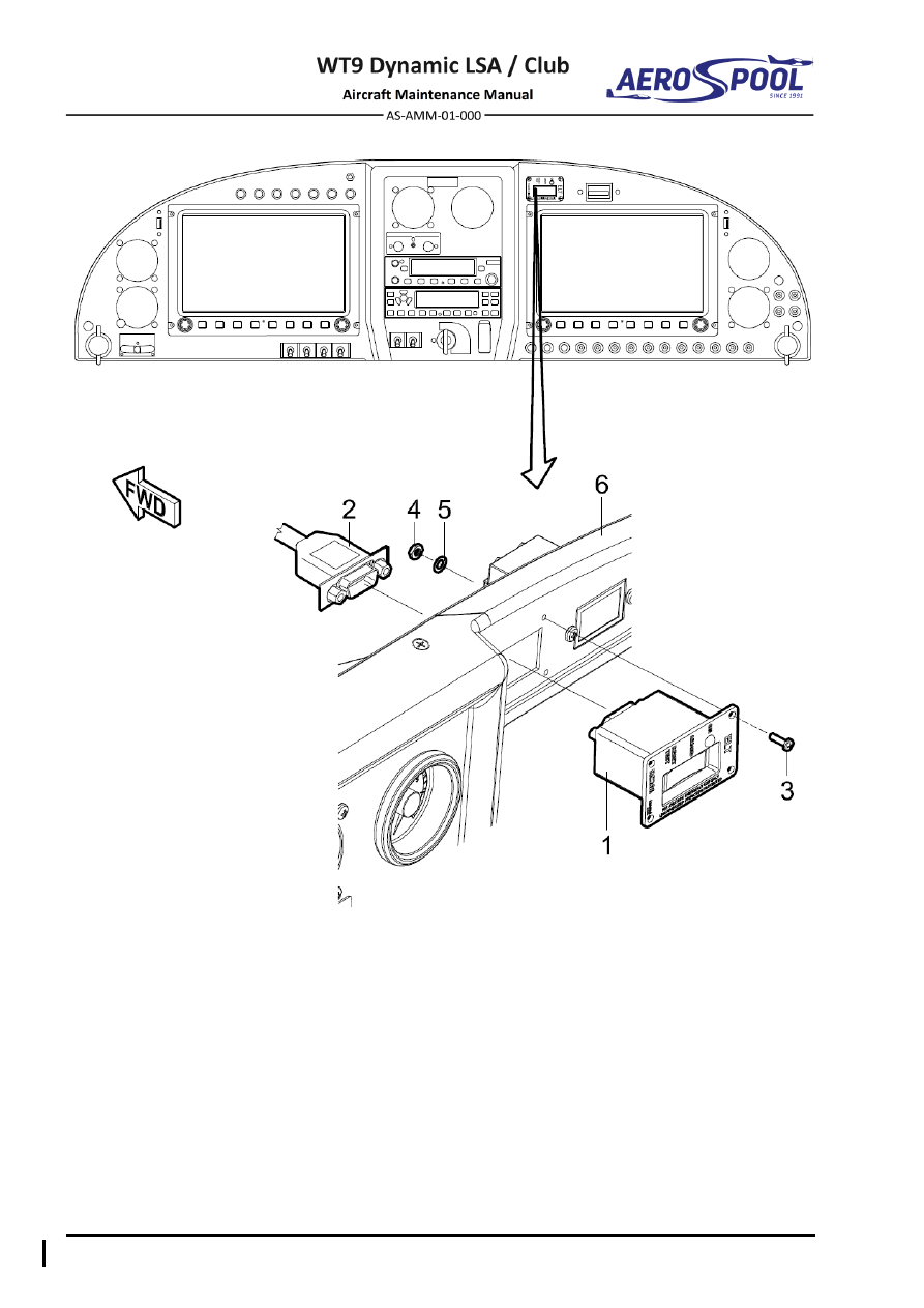
– ELT remote unit 

– Washer 

ø

3.2 x 7 x 0.5 

– Connector 

For information: 

– Screw M3 x 10 

– Instrument panel 

– Self-locking nut M3 


Fig. 39-23  ELT Remote Control Unit Removal / Installation 


INSTRUMENT AND CONTROL PANELS  


INSTRUMENT AND 

CONTROL PANELS 


W.  Standby fuel pressure indicator 

Type of maintenance: 

Line 

Personnel qualification: 

Independent  certifying  staff  qualified  in  accordance 


with Part-66 or higher. 

Recommended tools, materials, persons and documentation: 

ITEM 

QUANTITY 

Wrench 9 

1 pc 

Oetiker pliers- Crimping pliers 

1 pc 

Persons 

Tab. 39-22 Recommended tools, materials, persons and documentation 

(1)  Standby fuel pressure indicator removal: 

(a)  Remove the instrument panel cover (Chapter 39-10, 2.A.(1)). 

(b)  Remove  the  clamp  (5,  Fig.  39-24)  and  disconnect  the  hose  (4)  

from the port of the instrument. 

(c)  Hold the instrument and remove the nut (3) and holder (2). 

(d)  Remove the instrument (1) from the panel. 

(e)  Put the caps on the hose and instrument port. 

(2)  Standby fuel pressure indicator installation: 

(a)  Remove the caps from the instrument port and hose. 

(b)  Put the instrument (1, Fig. 39-24) in position on the panel (6).  

(c)  Install the holder (2) and nut (3). 

(d)  Connect  the  hose  (4) to  the port  of  the  instrument  (1)  and  secure it  

with clamp (5). 

(e)  Install the instrument panel cover (Chapter 39-10, 2.A.(2)). 

(f) 

Carry out an operational test. 


Effectivity:

 ALL 

12. 06. 2020


INSTRUMENT AND 
CONTROL PANELS 


–  Standby fuel pressure indicator 

–  Spring clamp ø9 

–  Holder 

For information: 

–  Special nut NPT1/8 

–  Right instrument panel 

–  Hose 


Fig. 39-24  Standby Fuel Pressure Indicator Removal / Installation 


CONTENTS 


STANDARD PRACTICES 

 AND STRUCTURES- 

GENERAL 


51  STANDARD 

PRACTICES AND 

STRUCTURES - GENERAL 

CONTENTS 

GENERAL ......................................................................... 3


1.


INTRODUCTION ....................................................................... 3


A.


General safety information ................................................ 3


B.


Aircraft description ............................................................. 4


C.


Spare parts source ............................................................ 4


51-10


REPAIRS .......................................................................... 5


1.


GENERAL .................................................................................. 5


2.


REPAIR CLASSIFICATION ....................................................... 6


A.


Repair Class 1 ................................................................... 6


B.


Repair Class 2 ................................................................... 6


C.


Repair Class 3 ................................................................... 6


D.


Repair Class 4 ................................................................... 6


3.


CONSTRUCTION ...................................................................... 6


4.


MATERIALS .............................................................................. 7


A.


Epoxy system .................................................................... 7


B.


Reinforcements ................................................................. 8


C.


Rovings ............................................................................. 8


D.


Foams and fillers ............................................................... 9


E.


Paints ................................................................................ 9 


Effectivity:

 ALL 

04. 07. 2019


STANDAR PRACTICES  
AND STRUCTURES- 
GENERAL 


5.


REPAIR PREPARATION ........................................................ 10


A.


Repair Class 4 ................................................................ 10


B.


Repair Class 3 ................................................................ 10


C.


Repair Class 2 ................................................................ 11


D.


Repair Class 1 ................................................................ 12


6.


PLY LAY-UP SCHEME ........................................................... 13


7.


REPAIRS OF METAL PARTS ................................................. 17


8.


REPAIRS OF PLEXIGLASS ................................................... 17


9.


TEST FLIGHT AFTER REPAIR .............................................. 17


A.


Test flight flying time: ...................................................... 18


B.


Aircraft inspection before a Test flight: ............................ 18


C.


Test crew: ....................................................................... 18


51-20


EXTERIOR FINISH REPAIR ........................................... 19


1.


REPAIR SURFACES .............................................................. 19


A.


Puttying ........................................................................... 19


B.


Painting ........................................................................... 20


GENERAL 


STANDARD PRACTICES 

 AND STRUCTURES- 

GENERAL 


51-00  GENERAL 

1.  INTRODUCTION 

This chapter contains information and procedures applicable to all composite repairs 
as well as information and procedures for aircraft painting and priming. The basic 
elements of successful repair are; preparation of the laminate and repair material, 
proper mixing of resin, technique, and a complete cure cycle. If any element is not 
properly executed the repair will be substandard. 

A. 

General safety information 

In the production of composite parts worker is exposed to various hazardous 
chemicals. All used types of resins, hardeners, separators, paints, solvents are 
hazardous when in direct contact with skin and mucous membranes. Equally 
dangerous is the inhalation of the vapours. Another adverse health factor for 
working on composite parts is dust environment. Therefore, it is the duty to 
protect your health and the health of their employees. When working with 
chemicals, it is necessary to follow this safety information: 

CAUTION 

IN  ALL  PRODUCTION  SPACES  IS  FORBIDDEN  TO  EAT,  DRINK, 
SMOKE AND MANIPULATE WITH FIRE! 

  Working clothes must not be torn and must be appropriately tight to the body. 

It is recommended to use long trousers and a shirt or T-shirt with long 
sleeves. After contact with skin chemicals threaten burns and allergies. 
Dangerous are stubborn stains from epoxy mixture on your clothes, they can 
cause scratches; 

  When laminating use undamaged latex gloves, which go for wristbands. 

Damaged gloves immediately replace with new ones; 

  When working with the materials or products that are grounded, cut or drilled, 

a large quantity of dust creates. Therefore, protect the airway with a 
respiratory protective equipment; 

  When spraying, use protective clothing, respiratory protective equipment and 

goggles; 

  Any injuries must be treated and report it to your supervisor. Do not 

underestimate any injury! 


Effectivity:

 ALL 

22. 05. 2017


STANDAR PRACTICES  
AND STRUCTURES- 
GENERAL 


B. 

Aircraft description 

The WT9 Dynamic LSA is a single engine, two seat, cantilever low wing aircraft 
with a cruciform tail. The primary structures consist of glass and carbon fibre 
composite. The aircraft is equipped with fixed tricycle undercarriage with 
steerable nose wheel and emergency parachute system. This aircraft is 
intended for sporting, recreation and tourist flying in accordance with VFR day. 

C. 

Spare parts source 

Spare parts can be ordered from 

www.aerospool.sk

 under 

“Products / Dynamic 

WT9 / Spare Parts

” or writing by an e-mail 

spareparts@aerospool.sk


E-mail must contain the following information: 


Aircraft S/N 


Billing address 


Shipping address (if is not the same as the billing address) 


VAT (if is registered) 


Contact person name 


Contact person phone 


List of required spare parts (part number and quantity, see current 
Illustrated Parts Catalogue) 

NOTE 

The resins can only be distributed by the personal collection. 


REPAIRS 


STANDARD PRACTICES 

 AND STRUCTURES- 

GENERAL 


51-10  REPAIRS 

1.  GENERAL 

Type of maintenance: 

Heavy 

Personnel qualification: 

Independent certifying staff qualified in accordance 


with Part-66 or higher. 

Recommended tools, materials, persons and documentation: 

ITEM 

QUANTITY 

See Chapter 51-10, par. 4. 

AR 

Persons 

Tab. 51-1 Recommended tools, materials, persons and documentation 

The described procedures concern only to relatively minor damage. Large-scale 
repairs may be performed only by the manufacturer or authorized repair station. 
Sandwich shells, from which the aircraft comprises, are difficult to repair. The 
disclosed methods are applicable only to minor repairs of coatings sandwich shells. 

Every material used for repairs must be suitable for the appropriate repair. 

Before repairs provide a needed fabrics reserve in sufficient quantity. Fabrics are 
sensitive to moisture; therefore they need to be properly stored in a cool, dry, dark 
place. For proper storage, resin and fabric is necessary to follow the manufacturer's 
recommendations. 

Abrupt changes in the thickness of the laminate should be avoided in order to 
prevent stress concentration. If possible, cut pieces of fabric to be oval or circular 
instead of rectangular shape. The transition between the repaired and undamaged 
area should be gradual and as smooth as possible. 

Chamfering of the coarse fabric has to be in the range 1:50 to 1:100, the fine fabric 
has the no chamfering and must be folded. 

Epoxy resins, hardeners and all kinds of fabrics are hygroscopic. In the event of 
increase of water content in the resin or the hardener, the epoxy composition will be 
cloudy and milky appearance. This composition is unusable. 

A relative atmospheric humidity for lamination should be in the range of 20 to 50 %. 
At the relative humidity is higher than 50 %, the time to start gelation of the mixture 
reduces. Also increases the weight of the product due to moisture absorption of the 
epoxy mixture. Increased moisture during production has no significant effect on the 
mechanical properties of the cured product. 


Effectivity:

 ALL 

04. 07. 2019


STANDAR PRACTICES  
AND STRUCTURES- 
GENERAL 


When the elevator, rudder, aileron and wing flaps were repaired, the static moments 
and weights must be checked, whether they are within the permissible range 
according to Tab. 51-2. 

CONTROL SURFACE 

(PAINTED) 

PERMISSIBLE 

WEIGHT (kg) 

PERMISSIBLE STATIC 

MOMENT (N.cm) 

Aileron LH 

1.530 

– 1.690 

17.298 

– 30.298 

Aileron RH (including trim 
tab) 

2.042 

– 2.200 

17.298 

– 30.298 

Wing flap 

1.950 

– 2.450 

160.0 

– 195.0 

Elevator 

1.132 

– 1.338 

9.198 

– 20.398


Rudder 

1.611 

– 1.969 

(-38.5) 

– (-31.5) 

Tab. 51-2 Control Surfaces Weight and Moment Limits 

2.  REPAIR CLASSIFICATION 

The repairs are divided according to the influence to the airworthiness of all aircraft 
into following classes: 

A. 

Repair Class 1 

Large damages required a partial replacement of the airframe, large repairs or 
repair of main structure can be carried out only by the aircraft manufacturer or a 
repair workshop approved by local Civil Aviation Authority. The repair procedure 
is not provided and must be prepared individually after damage examination. 

B. 

Repair Class 2 

Destruction of the whole shell (also the inner laminate is destroyed), however 
small size only. 

C. 

Repair Class 3 

Simple surface damage (only the outer laminate is damaged) and small 
damage of the foam filling. 

D. 

Repair Class 4 

The damages caused by the scores and the scrapes without the outer laminate 
damage and without the breakage of the element. 

3.  CONSTRUCTION 

WT9 Dynamic LSA airframe consists of a sandwich shells from composite material. 
The shell is of three-layer construction. The external and internal shell layers are 
made of a glass and carbon fibre fabrics, which are saturated with a resin. Between 
them there is a filling from a hard foam panels (polyurethane foam HEREX from 3 to 
15 mm thick).


REPAIRS 


STANDARD PRACTICES 

 AND STRUCTURES- 

GENERAL 


4.  MATERIALS 

A. 

Epoxy system 

The laminates are made using following epoxy system type: 

ITEM 

TYPE 

MANUFACTURER 

Resin 

L 285 

Hexion Inc. 

Hardener 

H 287 

Hexion Inc. 


Mixing ratio of resin and hardener: 

ITEM 

RESIN : HARDENER 

Parts by weight 

100 : 40

±2 

Parts by volume 

100 : 50

±2 


The given mixing proportion of components must be observed as exactly as 
possible. Mixture of a resin and a hardener must be stirred thoroughly until there are 
no cloudiness and no bubbles in a vessel. 

The thickeners and the resin-fillers are added after stirring. 

Gel time is approximately 5-6 hours at 20-25 

°C. Initial curing is 24 hours at 20-25 °C. 

The mixture reaches final properties after 15 hours curing at a temperature 55 

°C. 


Effectivity:

 ALL 

22. 05. 2017


STANDAR PRACTICES  
AND STRUCTURES- 
GENERAL 


B. 

Reinforcements 

MARKING  WEAVE 

WEIGHT 

PER AREA


(g/m

2

APPLICATION 

GLASS FABRICS 

91111 

Cross twill 1/3 

106 

Outer skin, inner skin, 
aileron, wing, fuselage, 
wheel cover, canopy 
frame, fin 

92110 

Cross twill 2/2 

163 

Outer skin, inner skin, 
aileron, wing, fuselage, 
stabilizer, engine 
cowling, fin, rudder, 
landing gear leg cover 

92125 

Cross twill 2/2 

280 

Inner skin, fuselage, 
wheel cover, landing 
gear leg cover 

92145 

Unidirectional 

220 

Wing, fuselage 

90070 

Fibre cloth 

81 

Inner skin, stabilizer 

02037 

Fibre cloth 

49 

Outer skin, inner skin, 
winglets, elevator, rudder 

CARBON FABRICS 

CF 80 

Fibre cloth 

80 

Outer skin, inner skin, 
winglet, stabilizer, 
elevator 

CF 200 

Fibre cloth 

200 

Outer skin, fuselage, 
wing, engine cowling, 
canopy frame 

CF 140 

Unidirectional 

140 

Outer skin, winglet, 
stabilizer, canopy frame, 
fuselage 

HYBRID FABRICS 

CF/AR 160  Fibre cloth 

165 

Inner skin, fuselage, 
cockpit 


C. 

Rovings 

Carbon:


TORAYCA T700S 24K 1650 g /1000 m


Glass:


STARROV 908 2400 g / 1000 m


REPAIRS 


STANDARD PRACTICES 

 AND STRUCTURES- 

GENERAL 


D. 

Foams and fillers 

Rigid Foam:


HEREX C70.55


Resin Fillers:


Aerosil 

Cotton flakes 

Microballoons white (brown)


E. 

Paints 

ITEM 

Mipa 4+1 2K HS -Filler 

MIPA OC MISCHLACK-KONZENTRAT-Paint 

MIPA 2K-

HÄRTER H5- Hardener 

Mipa 2K- Thinner 

Mipa C85 2K-HS-Clearcoat 


Effectivity:

 ALL 

04. 07. 2019


STANDAR PRACTICES  
AND STRUCTURES- 
GENERAL 


5.  REPAIR PREPARATION 

For all repairs, it is important to know the number of layers of the laminate, density  
of weave and directional fabrics fibers orientation relative to the main part 
dimensions. 
The first step is removing all damage parts and all portion of the shell that has 
become delaminated from a damage area. Repair area wash with soap and dry up. 
Then degrease a repair area. Repaired surface roughen with the sandpaper  
No. 60 to 80. Areas that could be damaged and dirty during work protect with a foil. 
Fabrics must not have high relative air humidity, as necessary they dry up, for 
example by a hot air gun. 

Prepare clean vessels for stirring the mixtures of a resin and a hardener. 

A. 

Repair Class 4 

The erosion damages caused by the rain, the scores, the scrapes without  
the outer laminate damage require the lacquer works only. 

See Chapter 51-20 Exterior finish repair. 

In case of first cloth layer damage, then whole repair area cleans well and 
sands smooth with a sand paper. Prepare cloth on the foil, saturate with resin 
and lay on the repair area. If the resin is dry, the repair area can be puttied 
and repainted with lacquer. 

B. 

Repair Class 3 

On the damaged area of the outer shell cut a circular or rounded hole with 
sufficiently size. Make sure that all delaminated parts of the shell have been 
removed. If the foam is also damaged, remove it too, eventually to the internal 
shell layer. Tap the surroundings of the damage area to determine the extent  
of delamination from the foam. Remove the lacquer from the edge of the cut 
hole at least 4 cm by means sandpaper. 

Around the edge of the damaged area where the shell is still firmly bonded, 
chamfer the shell. For top thin cloth layer the chamfer about 15 mm is 
necessary. 

After chamfering the shell, blow out thoroughly the whole repair area including 
the pores of the foam. Now fill the hole in the foam with microballoons and 
simultaneously fill the pores of the exposed foam. Then lay necessary layer  
of patches with diagonal weave direction (stepwise largest patch first) over  
the damaged area. After hardening (app. 24 hours at 20-25 

°C) the damaged 

area should be smoothed, filled and painted. In smoothing take care that only 
the edges of the patches are sanded. 


Fig.  51-1  Repair Class 3


REPAIRS 


STANDARD PRACTICES 

 AND STRUCTURES- 

GENERAL 


C. 

Repair Class 2 

If there is a through hole in the sandwich shell, then remove all delaminated 
parts and sand the edge of the hole. Enlarge the hole until good bonding to the 
foam is evidenced. Then remove the foam next 20 mm around the hole while 
the inner fabric remains undamaged. On thus exposed inner fabric make 
chamfer around the circumference. Outer fabric layer chamfer about 20 mm. 


Fig.  51-2  Repair Class 2 

– Step 1 

If the hole is not greater than 10 cm, then glue with Super Glue a thin laminate 
plate from bottom of the hole. Glued laminate can be supported by means of the 
nail or wire. Then lay inner layer of patches. Allow the inner layer harden before 
doing further work. Prepare the foam plug that will be inserted according the 
hole. If necessary warm the foam with hairdryer and bend. Scratch the previous 
layered patches with sandpaper 80 to ensure good glued contact. Glue the 
foam plug in the hole with thickened resin (microballoons) to close the pores. 
Make sure no air bubbles occur especially in inner corners.  If necessary add 
weight to ensure better contact. Let the epoxy accomplish (app. 24 hours at 
room temperature). 


Fig.  51-3  Repair Class 2 

– Step 2 

Once the epoxy is accomplished it can be smoothed, puttied with epoxy 
thickened with microballoons to close the pores and the outer laminate layers 
applied. 


Fig.  51-4  Repair Class 2 

– Step 3


Effectivity:

 ALL 

22. 05. 2017


STANDAR PRACTICES  
AND STRUCTURES- 
GENERAL 


D. 

Repair Class 1 

These repairs have serious character and can be carried out only by the aircraft 
manufacturer or a repair workshop approved by local Civil Aviation Authority 
(CAA). In any case contact the aircraft manufacturer.


REPAIRS 


STANDARD PRACTICES 

 AND STRUCTURES- 

GENERAL 


6.  PLY LAY-UP SCHEME 


Fig.  51-5  Ply Lay-up (page 1 of 2) 


Content      ..     31      32      33      34     ..