WT9 Dynamic LSA. AIRCRAFT MAINTENANCE MANUAL (AS-AMM-01-000, 22. 05. 2017) - page 32
 

  Index      Manuals     WT9 Dynamic LSA. AIRCRAFT MAINTENANCE MANUAL (AS-AMM-01-000, 22. 05. 2017)


Search            copyright infringement  


Content      ..     30      31      32      33     ..


WT9 Dynamic LSA. AIRCRAFT MAINTENANCE MANUAL (AS-AMM-01-000, 22. 05. 2017) - page 32


Effectivity:

 ALL 

12. 06. 2020


INSTRUMENT AND 
CONTROL PANELS 


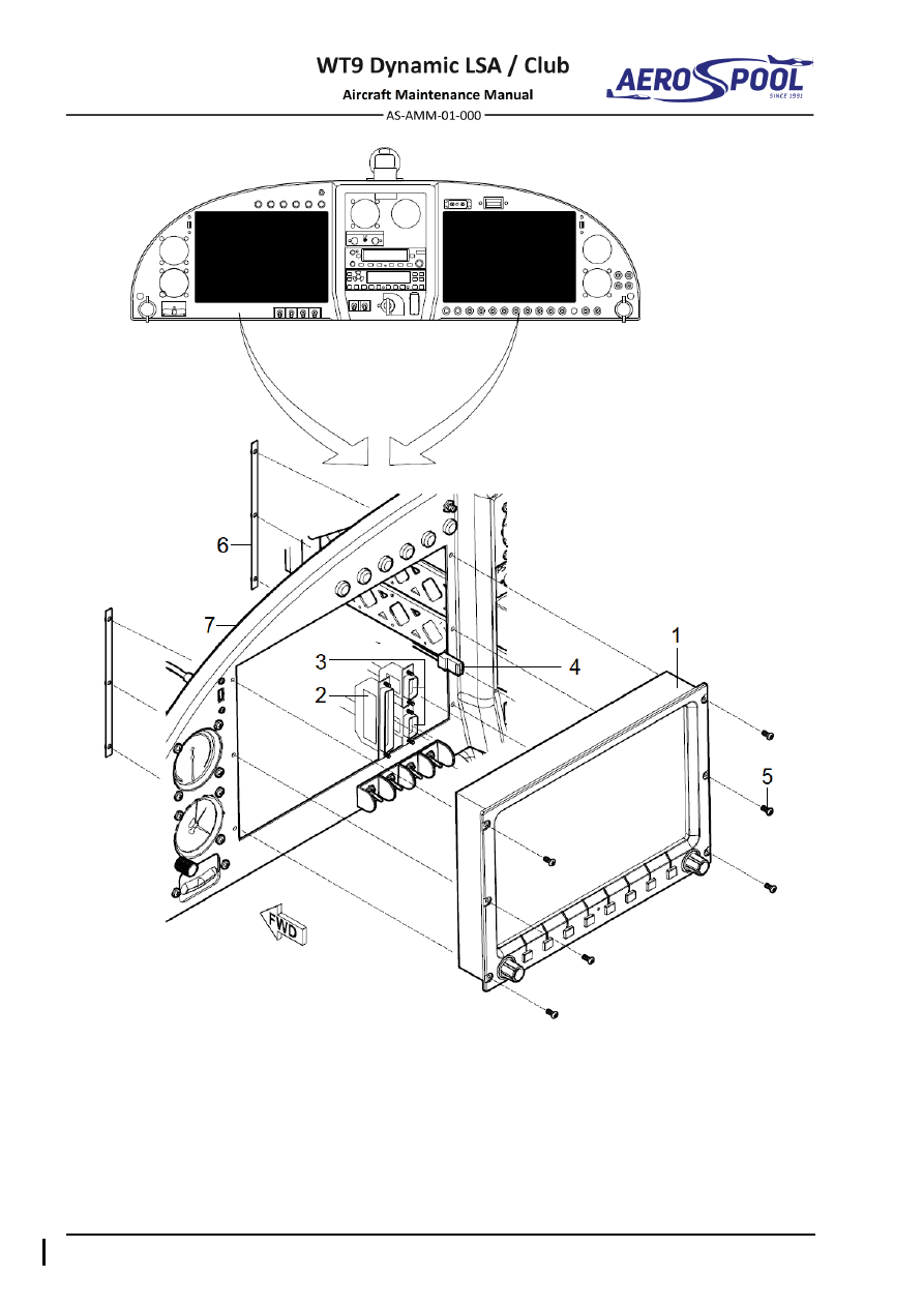
– SV-D1000 display 

– Screw M3 x 16 

– DB37 display connector 

– Skyview console 

– SkyView network connector 

For information: 

– Ethernet connector 

– Instrument panel 

Fig. 39-16  SV-D1000 Display Removal / Installation 


INSTRUMENT AND CONTROL PANELS  


INSTRUMENT AND 

CONTROL PANELS 


P. 

PM3000 intercom 

Type of maintenance: 

Line 

Personnel qualification: 

Independent  certifying  staff  qualified  in  accordance 


with Part-66 or higher. 

Recommended tools, materials, persons and documentation: 

ITEM 

QUANTITY 

Philips screwdriver 

1 pc 

Persons 

Tab. 39-15 Recommended tools, materials, persons and documentation 

(1)  PM-3000 intercom removal: 

(a)  Set 

MASTER SWITCH

 to 

OFF

 position. 

(b)  Remove the instrument panel cover (Chapter 39-10, 2.A.(1)).  

(c)  Disconnect the connector (5, Fig. 39-17) from the unit (1). 

(d)  Remove the mounting screws (4), knobs (2) and face plate (3); hold 

the unit. 

(e)  Remove the unit (1) from the instrument panel (6). 

(2)  PM-3000 intercom installation: 

(a)  Insert  the  unit  (1,  Fig.  39-17)  from  behind  the  instrument  panel  (6), 

aligning the holes for knobs, LED, and switch; hold the unit. 

(b)  Place  the  faceplate  (3)  over  the  knob  shafts  and  install  attaching 

screws (4). 

(c)  Install knobs (2) over the volume and squelch control shafts. 

(d)  Connect the connector (5) to the unit.  

(e)  Install the instrument panel cover (Chapter 39-10, 2.A.(2)).  

(f) 

Set 

MASTER SWITCH

 to 

ON

 position.  

(g)  Carry out a function test. 

(3)  PM-3000 intercom adjustment / function test: 

(a)  Apply power to the aircraft and avionics. 

(b)  Plug headsets into the pilot and co-pilot positions. 

(c)  Verify that the pilot position can transmit and receive with the intercom 

in  the  OFF  position  (left  hand  knob  controls  on/off  by  push  on-push 
off). 

(d)  Push the volume knob to switch the PM3000 on. Rotate the volume 

clockwise,  about  half  way.  Verify  that  the 

Pwr/Xmt

  light  comes  on 

green.  If  the  LED  is  blue  (or  red,  depending  upon  serial  number), 
immediately  switch  off  the  avionics,  and  troubleshoot  the  PTT 
installation. 

(e)  Verify that the pilot can transmit and receive on the communications 

transceivers. 

(f) 

Verify proper intercom operation for pilot and co-pilot. 


Effectivity:

 ALL 

12. 06. 2020


INSTRUMENT AND 
CONTROL PANELS 
 

(g)  Verify proper transmit and receive operation on the co-pilot position, 

noting that the co-pilot PTT switch allows proper transmission. 

(h)  Verify proper Intercom system operation in the ALL, ISO modes. 

(i) 

Verify  that  the  intercom  system  does  not  adversely  affect  any  other 
aircraft  system by systematically switching the unit on and off,  while 
monitoring the other avionics and electrical equipment on the aircraft. 


– Intercom 

– Electrical connector 

– Knob, outer and inner 

For information: 

– Face plate 

– Central instrument panel 

– Screw of intercom 


Fig. 39-17  PM3000 Intercom Removal / Installation 


INSTRUMENT AND CONTROL PANELS  


INSTRUMENT AND 

CONTROL PANELS 


Q. 

Radio Garmin GNC 255A NAV/COMM 

Type of maintenance: 

Line 

Personnel qualification: 

Independent  certifying  staff  qualified  in  accordance 


with Part-66 or higher. 

Recommended tools, materials, persons and documentation: 

ITEM 

QUANTITY 

Allen wrench 3/32” 

1 pc 

Persons 

Tab. 39-16 Recommended tools, materials, persons and documentation 

(1)  Radio Garmin GNC 255A NAV/COMM removal: 

(a)  Set 

MASTER SWITCH

 to 

OFF

 position. 

(b)  Put  a  3/32  Allen  wrench  into  the  access  hole  (2,  Fig.  39-18)  

for the locking screw; engage the screw. 

(c)  Turn  the  screw  anticlockwise  until  the  unit  (1)  disengages  

from the mounting rack. 

CAUTION 

DO  NOT  PULL  ON  THE  KNOBS.  DO  NOT  PRY  THE  FACE-
PLATE. YOU CAN DAMAGE THE UNIT. 

DO NOT TOUCH THE CONNECTOR CARD AT THE REAR OF 
THE UNIT. THE ELECTROSTATIC CHARGE ON YOUR BODY 
CAN DAMAGE THE UNIT. 

(d)  Pull gently on the sides of the unit (1) to remove it from the mounting 

rack (3). 

(e)  Install the protective covers on the rear connectors of the unit. 

(2)  Radio Garmin GNC 255A NAV/COMM installation: 

(a)  Remove  the  protective  covers  from  the  connectors  on  the  unit 

(1, Fig. 39-18).  

(b)  Looking  at  the  bottom  of  the  unit,  make  sure  the  front  lobe  

of the locking mechanism is in vertical position. 

(c)  Slide the unit (1) into the rack (3). Engage the locking screw so that 

the latch front lobe touches the rack. 

(d)  Turn  the  locking  screw  clockwise  so  that  the  rear  lobe  engages  

the mounting rack. 

(e)  Continue to turn the screw until the unit is fully installed in the mounting 

rack. 

CAUTION 

DO NOT OVER-TIGHTEN THE LOCKING SCREW. YOU CAN 
DAMAGE THE LOCKING MECHANISM. 


Effectivity:

 ALL 

12. 06. 2020


INSTRUMENT AND 
CONTROL PANELS 
 

(f) 

Set 

MASTER  SWITCH

  to 

ON

  position  and  carry  out  setting  (as 

necessary)  and  operational  test  -  refer  to  the  Garmin  GTR  225  /  
GNC  255  TSO  Installation  Manual,  P/N  190-01182-02  (revision  B  
or later). 


– GNC 255A NAV/COMM unit 

For information: 

– Access hole for locking screw 

– Mounting rack 

Fig. 39-18  Garmin GNC 255A NAV/COMM Removal / Installation 


INSTRUMENT AND CONTROL PANELS  


INSTRUMENT AND 

CONTROL PANELS 


R. 

Transponder Garmin GTX 328 / GTX 335 

Type of maintenance: 

Line 

Personnel qualification: 

Independent  certifying  staff  qualified  in  accordance 


with Part-66 or higher. 

Recommended tools, materials, persons and documentation: 

ITEM 

QUANTITY 

Allen wrench 3/32” 

1 pc 

Persons 

Tab. 39-17 Recommended tools, materials, persons and documentation 

(1)  Transponder Garmin GTX 328 / GTX 335 removal: 

(a)  Set 

MASTER SWITCH

 to 

OFF

 position. 

(b)  Put  a  3/32  Allen  wrench  into  the  access  hole  (2,  Fig.  39-19)  

for the locking screw; engage the screw. 

(c)  Turn  the  screw  counter-clockwise  until  the  unit  (1)  disengages  

from the mounting rack. 

CAUTION 

DO  NOT  PULL  ON  THE  KNOBS.  DO  NOT  PRY  THE  FACE-
PLATE. YOU CAN DAMAGE THE UNIT. 

DO  NOT  TOUCH  THE  CONNECTOR  CARD  AT  THE  REAR  
OF  THE  UNIT.  THE  ELECTROSTATIC  CHARGE  ON  YOUR 
BODY CAN DAMAGE THE UNIT. 

(d)  Pull gently on the sides of the unit (1) to remove it from the mounting 

rack (3). 

(e)  Install the protective covers on the rear connectors of the unit. 

(2)  Transponder Garmin GTX 328 / GTX 335 installation: 

(a)  Remove  the  protective  covers  from  the  connectors  on  the  unit  

(1, Fig. 39-19). 

(b)  Looking  at  the  bottom  of  the  unit,  make  sure  the  front  lobe  

of the locking mechanism is in a vertical position. 

(c)  Slide the unit (1) into the rack (3). Engage the locking screw so that 

the latch front lobe touches the rack. Turn the locking screw clockwise 
so  that  the  rear  lobe  engages  the  mounting  rack.  Continue  to  turn  
the screw until the unit is fully installed in the mounting rack. 

CAUTION 

DO NOT OVER-TIGHTEN THE LOCKING SCREW. YOU CAN 
DAMAGE THE LOCKING MECHANISM. 

(d)  Set 

MASTER  SWITCH

  to 

ON

  position  and  carry  out  setting  

(as  necessary)  and  operational  test  -  refer  to  the  Garmin  GTX  328 
Transponder  Installation  Manual,  P/N  190-00420-04  (revision  C  
or  later)  /  Garmin  GTX  335  Transponder  Inst.  Manual,  
P/N 190-01499-02 (revision 14 or later).


Effectivity:

 ALL 

12. 06. 2020


INSTRUMENT AND 
CONTROL PANELS 


– Transponder GTX 328 / GTX 335 (unit) 

For information: 

– Access hole for locking screw 

– Mounting rack 

Fig. 39-19  Transponder Garmin GTX 328 / GTX 335 Removal / Installation 


INSTRUMENT AND CONTROL PANELS  


INSTRUMENT AND 

CONTROL PANELS 


S. 

Magnetic compass 

Type of maintenance: 

Line 

Personnel qualification: 

Independent  certifying  staff  qualified  in  accordance 


with Part-66 or higher. 

Recommended tools, materials, persons and documentation: 

ITEM 

QUANTITY 

Non-magnetic Philips screwdriver 

1 pc 

Non-magnetic wrench 7 

1 pc 

Persons 

Tab. 39-18 Recommended tools, materials, persons and documentation 

WARNING 

WHEN 

PERFORMING 

MAINTENANCE 

PRACTICES 

ON  

THE  MAGNETIC  COMPASS,  USE  A  NON-MAGNETIC  OR  PLASTIC 
SCREWDRIVER. 

(1)  Magnetic compass removal: 

(a)  Remove  screws  and  carefully  lift  the  instrument  panel  cover 

(Chapter 39-10, 2.A.(1)).  

(b)  Remove  the  mounting  nuts  (3,  Fig.  39-20),  washers  (4)  and  screws 

(2). 

(c)  Remove compass (1). 

(2)  Magnetic compass installation: 

(a)  Place the compass (1, Fig. 39-20) on the instrument panel cover (5); 

hold the compass and attach it with screws (2), washers (4) and nuts 
(3). 

(b)  Install the instrument panel cover (Chapter 39-10, 2.A.(2)). 

(3)  Magnetic compass adjustment / test: 

Carry out a test for correct operation of the compass (compass swing): 


After replacing a major component  


After replacing the compass 


After modification to the aircraft. 

Compass swing must be performed on the approved compass swing area, 
which is at least 100 m (300 ft) from steel structures, electric leading or other 
over ground or underground steel equipment or objects. 

Compass  swing  is  carried  out  twice.  During  the  individual  test  different 
aircraft  electrical  equipment  are  switched  on  as  mentioned  in  the  form 
(Fig. 39-21). 


Effectivity:

 ALL 

12. 06. 2020


INSTRUMENT AND 
CONTROL PANELS 
 

If  the  compass  north  is  westward  from  magnetic  north,  the  deviation  is 
westward,  i.e.  negative.  If  the  compass  north  is  eastward  from  magnetic 
north, the deviation is eastward, i.e. positive. 


CAUTION 

USE ONLY NON-MAGNETIC TOOLS TO ADJUST THE COMPASS. 

DO  NOT  WEAR  OR  CARRY  METALLIC  MATERIAL  (WATCHES, 
BRACELETS  ETC.)  WHEN  YOU  ADJUST  THE  COMPENSATING 
MAGNETS  OR  OPERATE  THE  LAND  COMPASS.  METALLIC 
MATERIAL CAN CAUSE ERRORS. 

(4)  Magnetic compass swing procedure: 

(a)  Place the aircraft on the approved compass swing area. 

(b)  Set appropriate electrical equipment to ON (see form Fig. 39-21). 

(c)  Align the aircraft to magnetic north 

“N”. Adjust the N-S compensator 

so that the compass indicates a heading of 0 degrees. 

(d)  Align  the  aircraft  to  magnetic  east 

“E”. Adjust the E-W compensator  

so that the compass indicates a heading of 90 degrees. 

(e)  Align the aircraft to magnetic south 

“S”. Reduce the found out deviation 

to the half value by the N-S compensator. 

(f) 

Align the aircraft to magnetic west 

“W”. Reduce the found out deviation 

to the half value by E-W compensator. 

(g)  Turn the aircraft through 360 degrees by grades in magnetic compass 

compensation  record.  Record  the  deviation  at  each  30  degrees. 
Prepare  a  deviation  table  that  shows  the  corrections  that  must  
be applied to each heading. If large deviations occur when you operate 
electrical  equipment/systems,  the  deviation  table  must  also  show  
the  corrections  to  apply  at  each  30  degrees  heading  when  
the system is operated. 

(h)  Install  the  deviation  table  in  the  compass  card  holder  below  

the compass. 


INSTRUMENT AND CONTROL PANELS  


INSTRUMENT AND 

CONTROL PANELS 


– Magnetic compass 

– Washer 4.3 x 9 x 0.8 brass 

– Screw M4x10 aluminum 

For information: 

– Low nut M4 (brass) 

– Instrument panel cover 

Fig. 39-20  Magnetic compass Removal / Installation 


Effectivity:

 ALL 

12. 06. 2020


INSTRUMENT AND 
CONTROL PANELS 


MAGNETIC COMPASS COMPENSATION RECORD 

Aircraft


Type/Model:

  WT9 Dynamic LSA / Club 

Serial number:


Compass


Type:


Serial number:


Conditions:


Measurement 1 

Measurement 2 

A. 

Aircraft stands on landing gear. 

B. 

All electrical equipment ON and 
operating. 

C. 

XPDR ON, COMM receiving.


A. 

Aircraft stands on landing gear. 

B. 

Switched ON only those 
instruments, which are 
necessary for VFR flight. 
COMM, NAV, XPDR, lights 
switched OFF.


Heading 

Measured


Deviation 

Measured


Deviation 

N   000 


  030 


  060 


E  090 


  120 


  150 


S  180 


  210 


  240 


W  270 


  300 


  330 


Notes: 
Maximum allowed deviation ± 5°


General evaluation:


  Passed 

  Failed 


Performed by:


Name, date, signature


Fig. 39-21  Compass Compensation Record 


INSTRUMENT AND CONTROL PANELS  


INSTRUMENT AND 

CONTROL PANELS 


T. 

Ignition switches 

Type of maintenance: 

Line 

Personnel qualification: 

Independent  certifying  staff  qualified  in  accordance 


with Part-66 or higher. 

Recommended tools, materials, persons and documentation: 

ITEM 

QUANTITY 

Socket wrench 10 

1 pc 

Soldering gun 

1 pc 

Shrink tube ø3.2 x 1.6 mm 

AR 

Knife 

1 pc 

Pliers 

1 pc 

Aircraft Wiring Manual (Doc. No. AS-AWM-01-000) 

Persons 

Tab. 39-19 Recommended tools, materials, persons and documentation 

NOTE 

Removal / installation are the same for both switches. 

(1)  Ignition switch removal: 

(a)  Remove the engine cowlings (Chapter 71-10). 

(b)  Disconnect the battery. 

(c)  Remove the instrument panel cover (Chapter 39-10, 2.A.(1)).  

(d)  Unscrew the nut (10, Fig. 39-22), remove the washers (8; 9) and pull 

out the switch (7). 

(e)  Remove shrink tubes and unsolder the el. wires (11). 

(2)  Ignition switch installation: 

(a)  Make sure that the battery is disconnected. 

(b)  Put  on  the  wires  (11,  Fig.  39-22)  shrink  tube,  using  soldering  gun 

connect wires to the switch (7); pull the shrink tube over join. 

(c)  Place the switch (7) on the back of the instrument panel. 

(d)  Insert the washers (8; 9), screw and tighten the nut (10). 

(e)  Connect the battery. 

(f) 

Install the engine cowlings (Chapter 71-10). 

(g)  Install the instrument panel cover (Chapter 39-10, 2.A.(2)).  

(h)  Carry out an operational test. 


Effectivity:

 ALL 

12. 06. 2020


INSTRUMENT AND 
CONTROL PANELS 


Fig. 39-22  Ignition Switches Removal / Installation (page 1 of 2) 


INSTRUMENT AND CONTROL PANELS  


INSTRUMENT AND 

CONTROL PANELS 


–  Keyed ignition switch 

–  Switch 

–  Nut 

–  Washer of switch 

–  Washer of ignition switch 

–  Serrated washer 

–  Knurled ring 

10 

–  Nut 

–  Screw M3 x 10 

11 

–  Wires 

–  El. wires 


Fig. 39-22  Ignition Switches Removal / Installation (page 2 of 2) 


Effectivity:

 ALL 

12. 06. 2020


INSTRUMENT AND 
CONTROL PANELS 
 

U. 

Keyed ignition switch 

Type of maintenance: 

Line 

Personnel qualification: 

Independent  certifying  staff  qualified  in  accordance 


with Part-66 or higher. 

Recommended tools, materials, persons and documentation: 

ITEM 

QUANTITY 

Wrench 22 

1 pc 

Pliers 

1 pc 

Philips screwdriver 2 

1 pc 

Aircraft Wiring Manual (Doc. No. AS-AWM-01-000) 

Persons 

Tab. 39-20 Recommended tools, materials, persons and documentation 

(1)  Keyed ignition switch removal: 

(a)  Remove the engine cowlings (Chapter 71-10). 

(b)  Disconnect the battery. 

(c)  Remove the instrument panel cover (Chapter 39-10, 2.A.(1)).  

(d)  Remove key from the switch (1, Fig. 39-22) and disconnect the wires 

(6) from the switch. 

(e)  Remove the screw (5) and knurled ring (4). 

(f) 

Pull out the switch (1) with washer (3). 

(2)  Keyed ignition switch installation: 

(a)  Make sure that the battery is disconnected. 

(b)  Connect the wires (6, Fig. 39-22) to the switch (1).  

(c)  Put the switch (1) with washer (3) in position in the instrument panel. 

(d)  Hold the switch and attach it with and knurled ring (4) and screw (5). 

(e)  Connect the battery. 

(f) 

Install the engine cowlings (Chapter 71-10). 

(g)  Install the instrument panel cover (Chapter 39-10, 2.A.(2)).  

(h)  Carry out an operational test. 

(3)  Keyed ignition switch test: 

(a)  Disconnect connector of ignition switch. Use the multimeter to check  

if  ignition  switches  are  in 

OFF

  position,  wires  B1-MAG1,  B1-MAG2 

with negative terminal, circuit is closed. When the ignition switches are 
switched 

ON

,  wires  B1-MAG1,  B1-MAG2  with  negative  terminal, 

circuit is open. 


INSTRUMENT AND CONTROL PANELS  


INSTRUMENT AND 

CONTROL PANELS 


V. 

ELT remote control unit 

Type of maintenance: 

Line 

Personnel qualification: 

Independent  certifying  staff  qualified  in  accordance 


with Part-66 or higher. 

Recommended tools, materials, persons and documentation: 

ITEM 

QUANTITY 

Philips screwdriver 

1 pc 

Wrench 7 

1 pc 

Persons 

Tab. 39-21 Recommended tools, materials, persons and documentation 

(1)  ELT remote control unit removal: 

(a)  Remove the instrument panel cover (Chapter 39-10, 2.A.(1)). 

(b)  Disconnect the connector (2, Fig. 39-23) from the unit (1). 

(c)  Remove mounting nuts (4), washers (5) and screws (3). 

(d)  Remove the unit (1) from the instrument panel (6). 

(2)  ELT remote control unit installation: 

(a)  Put the unit (1, Fig. 39-23) in the instrument panel (6). 

(b)  Hold the unit and attach it with screws (3), washers (5) and nuts (4). 

(c)  Connect the connector (2) to the unit. 

(d)  Install the instrument panel cover (Chapter 39-10, 2.A.(2)). 

(e)  Carry out an operational test - refer to the Installation and Operation 

Manual  ELT  KANNAD  406  AF-COMPACT,  Doc.  No.  DOC08038F 
(Revision  05  or  later)  /  Initial  Installation  Manual  KANNAD  
AF  INTEGRA,  Doc.  No  DOC09081E  (Revision  04  or  later)  and 
Operation  Manual  KANNAD  AF  INTEGRA  Doc.  No  DOC09078E 
(Revision 04 or later). 


Content      ..     30      31      32      33     ..