WT9 Dynamic LSA. AIRCRAFT MAINTENANCE MANUAL (AS-AMM-01-000, 22. 05. 2017) - page 34
 

  Index      Manuals     WT9 Dynamic LSA. AIRCRAFT MAINTENANCE MANUAL (AS-AMM-01-000, 22. 05. 2017)


Search            copyright infringement  


Content      ..     32      33      34      35     ..


WT9 Dynamic LSA. AIRCRAFT MAINTENANCE MANUAL (AS-AMM-01-000, 22. 05. 2017) - page 34


Effectivity:

 ALL 

22. 05. 2017


STANDAR PRACTICES  
AND STRUCTURES- 
GENERAL 


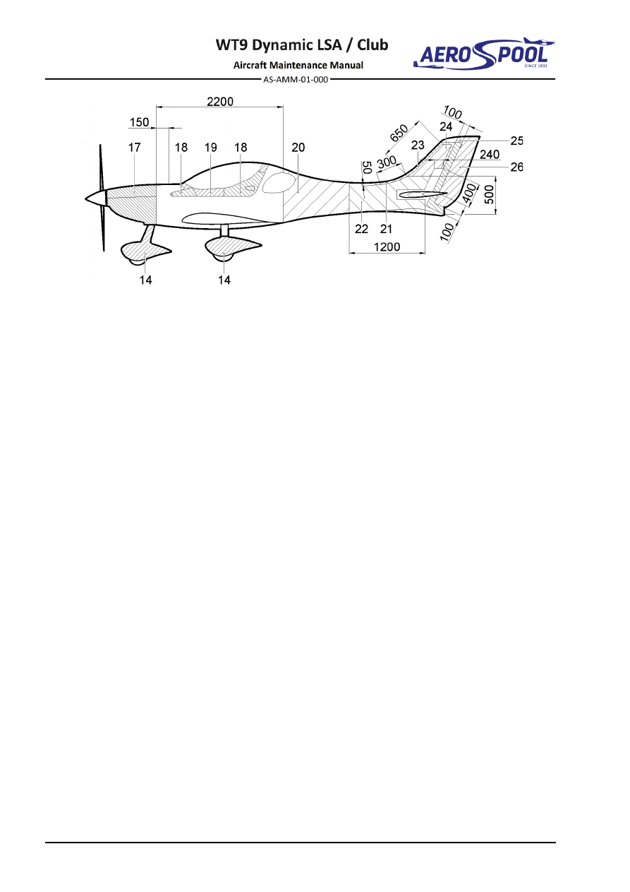
Fig.  51-5  Ply Lay-up (page 2 of 2) 

Each fabric must be properly oriented with respect to the long side of the aircraft. The 
patch must be composed of an equal number of layers as a repair area plus one 
technology layer that prevents damage of the top layer due to finishing. 

The table shows the layers necessary for repairs in order from the outer to the inner. 

Repair the damage are allowed only 5 cm from the spar, rib or bulkhead. If there was 
also damage the spar, bulkhead, contact the manufacturer. 

If the collar on the leading edges of the wings and horizontal stabilizer is damaged, it 
is necessary to laminate new ones. 


REPAIRS 


STANDARD PRACTICES 

 AND STRUCTURES- 

GENERAL 


ITEM 

LAYER 

POSITION 

LAYER 

WEAVE 

DIRECTION 

NOTE 

Outer 

02037 

Technological 

layer 

Outer 

02037 


Outer 

CF80 


Outer 

CF140 


Herex 


3 mm 

Inner 

CF80 


Outer 

92110 

Technological 

layer 

Outer 

92110 


Herex 


6 mm 

Inner 

92110 


Outer 

92110 

Technological 

layer 

Outer 

92110 


Herex 


3 mm 

Inner 

91111 


92110 

Technological 

layer 

92110 


92110 

Only for the 

leading edge 

collar 

92110 

Only for the 

leading edge 

collar 

91111 


Outer 

92110 

Technological 

layer 

Outer 

92110 


Outer 

92110 


Herex 


6 mm 

Inner 

91111 


Outer 

92110 

Technological 

layer 

Outer 

92110 


Outer 

CF200 


Herex 


8 mm 

Inner 

92110 


Outer 

92110 

Technological 

layer 

Outer 

92110 


Outer 

CF200 


Outer 

CF200 


Herex 


8 mm 

Inner 

92110 


ITEM 

LAYER 

POSITION 

LAYER 

WEAVE 

DIRECTION 

NOTE 

Outer 

CF80 

Technological 

layer 

Outer 

CF80 


Herex 


5 mm 

Inner 

90070 


Outer 

CF80 

Technological 

layer 

Outer 

CF80 


Outer 

CF140 


Herex 


5 mm 

Inner 

90070 


10 

92110 

Technological 

layer 

92110 


92110 


92110 


90070 


3x92110 

Splicing collar 

11 

Outer 

CF80 

Technological 

layer 

Outer 

CF80 


Herex 


3 mm 

Inner 

02037 


12 

Outer 

92110 

Technological 

layer 

Outer 

92110 


Outer 

92110 


Herex 


5 a 8 mm 

Inner 

91111 


Inner 

92125 


13 

Outer 

92110 

Technological 

layer 

Outer 

92110 


Outer 

92110 


Herex 


5 a 8 mm 

Inner 

91111 


14 

91111 

Technological 

layer 

91111 


92125 


92125 

Only 70 mm 

around the 

cutout of the 

wheel and its 

attachment 

92125 


Effectivity:

 ALL 

22. 05. 2017


STANDAR PRACTICES  
AND STRUCTURES- 
GENERAL 


ITEM 

LAYER 

POSITION 

LAYER 

WEAVE 

DIRECTION 

NOTE 

15 

92110 

Technological 

layer 

92110 


92110 


92110 


92110 


16 

92110 

Technological 

layer 

92110 


CF200 


91111 


17 

92110 

Technological 

layer 

92110 


CF200 


CF200 


18* 

91111 

Technological 

layer 

91111 


CF200 


CF200 


CF140 


19* 

91111 

Technological 

layer 

91111 


CF200 


CF140 


20 

Outer 

92110 

Technological 

layer 

Outer 

92110 


Outer 

CF140 


Herex 


5 mm 

Inner 

91111 


21 

92110 

Technological 

layer 

92110 


92110 


92110 


91111 


CF140 


CF200 


91111 


ITEM 

LAYER 

POSITION 

LAYER 

WEAVE 

DIRECTION 

NOTE 

22 

Outer 

92110 

Technological 

layer 

Outer 

92110 


Outer 

91111 


Outer 

CF140 


Herex 


5 mm 

Inner 

91111 


23 

92110 

Technological 

layer 

92110 


92110 


92110 


91111 


24 

Outer 

92110 

Technological 

layer 

Outer 

92110 


Herex 


5 mm 

Inner 

91111 


25 

Outer 

92110 

Technological 

layer 

Outer 

92110 


Outer 

92110 


Herex 


3 mm 

Inner 

02037 


26 

Outer 

92110 

Technological 

layer 

Outer 

92110 


Herex 


3 mm 

Inner 

02037 


27 

92110 

Technological 

layer 

92110 


92125 


* valid for the outer and as well as inner 
shell 


Tab. 51-3 Ply Lay-up 


REPAIRS 


STANDARD PRACTICES 

 AND STRUCTURES- 

GENERAL 


7.  REPAIRS OF METAL PARTS 

In case of a damage of any fittings, if a damage reason was not designate 
immediately, contact the aircraft manufacturer. It is necessary take account to an 
element function, a material composition, a processing technology and etc. The 
aircraft manufacturer can evaluate all these factors only. 

Welding should be carried out only by an approved aircraft welder. All welds made by 
the aircraft manufacturer are by the Argon-arc welding method. 

8.  REPAIRS OF PLEXIGLASS 

Type of maintenance: 

Line 

Personnel qualification: 

Independent certifying staff qualified in accordance 


with Part-66 or higher. 

Recommended tools, materials, persons and documentation: 

ITEM 

QUANTITY 

Driller 

Ø

1.5 

– 2.0 

AR 

Persons 

Tab. 51-4 Recommended tools, materials, persons and documentation 

Most  common  damage  which  occurs  on  plexiglass  are  cracks,  which  usually  start 
around  vent  windows  rails  as  result of  using  of  these  windows  to open or  close  the 
canopy. 

When  the  crack  occurs,  it  is  important  to  stop  its  propagation  immediately  after 
discovering  it.  This  can  be  done  by  drilling  a  hole  in  direction  of  crack  trajectory. 
The  hole  has  to  be  drilled  perpendicular  to  surface,  on  farthermost  visible  point  
of  the crack (crack tip).  This has to be done for each  crack tip, except  the end is in 
hole, or on edge. Diameter of the hole should not be less than 1 mm, and not greater 
than 2 mm. 

9.  TEST FLIGHT AFTER REPAIR 

WARNING 

ONLY QUALIFIED PILOT MAY PERFORM A TEST FLIGHT! 

The test flight should be performed above all in following cases: 

After repair or replace of fixed surfaces 

– wing, fin, stabilizer, or control surfaces – 

elevator, aileron and wing flap. Flight characteristics and aircraft stability can be 
affected when above mentioned part is replaced or adjusted. Therefore a test flight 
should be performed to check aircraft flight characteristics, control surfaces setting, 
manoeuvrability, stability, and stall characteristics. The characteristics are check 
during taxiing, takeoff, climbing, cruise, descent, approach and landing. The extend 
of flight test necessary to perform depends on the extend of repair. 


Effectivity:

 ALL 

04. 07. 2019


STANDAR PRACTICES  
AND STRUCTURES- 
GENERAL 


A. 

Test flight flying time: 

Test flight flying time depends on the extend of the tests necessary to perform 
after a repair. 

B. 

Aircraft inspection before a Test flight: 

Prior to the test flight the aircraft shall be thoroughly inspected, weighed, found 
faults debugged and the aircraft shall be prepared for the flight (replenishing 
etc.). 

C. 

Test crew: 

Only qualified persons (test pilots) are permitted to perform a test flight. In-flight 
found faults should be debugged forthwith the test flight 


.


EXTERIOR FINISH REPAIR 


STANDARD PRACTICES 

 AND STRUCTURES- 

GENERAL 


51-20  EXTERIOR FINISH REPAIR 

1.  REPAIR SURFACES 

During the operational life of the aircraft, small scratches and dents may appear on 
the composite surfaces. This damage needs to be repaired. Refinishing of the 
damage is permitted as long as there is no damage to the fiber fabrics. 

When control surfaces are painted, they must comply with weight and static moment 
range according to Tab. 51-2. 

A. 

Puttying 

Type of maintenance: 

Heavy 

Personnel qualification: 

Independent certifying staff qualified in accordance 


with Part-66 or higher. 

Recommended tools, materials, persons and documentation: 

ITEM 

QUANTITY 

Sandpapers to density 240 

Polyester putty 

Benzine 

Persons 

Tab. 51-5 Recommended tools, materials, persons and documentation 


(1)  Instructions: 

(a)  Localize and mark every dent. 

(b)  Sand the paint on the dent and the surrounding area using 

sandpaper 240. 

(c)  Degrease surface with Benzine. 

(d)  Mix required amount of putty, refer their manual. 

(e)  Apply required amount of putty on dent. 

(f) 

Let putty harden. 

(g)  Sand the repaired area with sandpaper 240. 

(h)  Any imperfections putty again and then re-sand. 

(i) 

Visually inspect and touch check. If surface is smooth without dents 
continue with painting. 


Effectivity:

 ALL 

22. 05. 2017


STANDAR PRACTICES  
AND STRUCTURES- 
GENERAL 


B. 

Painting 

Type of maintenance: 

Heavy 

Personnel qualification: 

Independent certifying staff qualified in accordance 


with Part-66 or higher. 

Recommended tools, materials, persons and documentation: 

ITEM 

QUANTITY 

Airbrush 

1 pc 

Brush 

1 pc 

Polishing pad 

AR 

Sandpapers 400-2000 

AR 

Mipa 4+1 2K HS -Filler 

AR 

MIPA OC MISCHLACK-KONZENTRAT-Paint 

AR 

MIPA 2K-

HÄRTER H5- Hardener 

AR 

Mipa 2K- Thinner 

AR 

Mipa C85 2K-HS-Clearcoat 

AR 

Grinding paste 

AR 

Polish  

AR 

Benzine 

AR 

Persons 

Tab. 51-6 Recommended tools, materials, persons and documentation 


(1)  Instructions: 

(a)  Localize and mark every dent. 

(b)  Sand surface with sandpapers to 400. 

(c)  Degrease surface with Benzine. 

(d)  Mix required amount of Filler, refer their manual. 

(e)  Apply required amount of layers of Filler on surface to smooth 

indentations.  

(f) 

Let filler harden. 

(g)  Smooth indentations with sandpapers to 1200. 

(h)  Any imperfections fill again and then smooth. 

(i) 

For small repairs use a brush, for bigger repairs use an airbrush. 
Apply paint in thin layers. Allow to harden.  

(j) 

Polish surface with a grinding paste. 

(k)  Visually inspect and touch check that surface is smooth without 

dents. 

(l) 

After painting on control surfaces their weight and inertia moment 
must be checked. 


GENERAL 


DOORS 

52-00  GENERAL 

1.  INTRODUCTION 

The aircraft is equipped with the canopy which enables the access into the cockpit. 


CANOPY FRAME 


DOORS 

52-10  CANOPY FRAME 

1.  DESCRIPTION 

The  aircraft  has  a  one-piece  tilting  canopy  (Fig.  52-1).  Canopy  frame  is  attached  
in front section to the fuselage using two hinges (2) and supported by two gas springs. 
It is opened in upside-forward direction. Guide pins located on both sides of the canopy 
frame ensures centering of the canopy during the closing. Canopy is equipped with 3 
mm  thick  Plexiglas  windshield  and  sliding  windows  on  both  sides.  The  frame  (1)  
is  a  hollow  laminate  structure,  through  which  flows  venting  air.  Canopy  is  fitted  
with  eyeball  vents  on  both  sides  and  holes  for  blowing  of  windshield  (see  
Chapter 21-20). Closing mechanism of canopy frame (3; 4) with handle (6) is situated 
in the middle of the frame in rear part of the canopy frame and is accessible from both 
- pilot and co-pilot seats. The canopy frame is also equipped with a canopy lock (5). 
Closing  mechanism  is  secured  only  when  the  lock  lever  is  fully  plugged  backwards 
(red ring indicates correct locking).  

The towing version and aircraft from S/N 21001 are equipped with rear mirror fitting (7) 
installed inside of canopy frame (1). 


Fig.  52-1  Canopy Frame (page 1 of 2) 


Effectivity:

 ALL 

24. 11. 2020


DOORS 


–  Canopy frame 

–  Canopy lock 

–  Canopy hinge 

–  Handle 

–  Canopy closing mechanism handle (exterior)  7 –  Mirror fitting 

–  Canopy closing mechanism handle (interior)   

Fig.  52-1  Canopy Frame (page 2 of 2)


CANOPY FRAME 


DOORS 

2.  MAINTENANCE PRACTICES 

A. 

Canopy frame 

Type of maintenance: 

Line 

Personnel qualification: 

Independent  certifying  staff  qualified  in  accordance 


with Part-66 or higher. 

Recommended tools, materials, persons and documentation: 

ITEM 

QUANTITY 

Screwdriver 

1 pc 

Pliers 

1 pc 

Wrench 10 

1 pc 

Blinder 

ø30 mm 

2 pcs 

Persons 

Tab. 52-1 Recommended tools, materials, persons and documentation 

(1)  Canopy frame removal: 

CAUTION 

DURING  CANOPY  FRAME  REMOVAL,  PAY  ATTENTION  NOT  
TO SCRATCH THE WINDSHIELD! 

(a)  Remove blinders (10, Fig. 52-2). 

(b)  Open the canopy frame (1). 

(c)  Disconnect upper end of gas springs (2) on both sides of the canopy 

frame (1) (see par. 2. B (1)). 

(d)  Remove safety pins (6), unscrew nuts (4) and remove washers (5). 

(e)  Remove the canopy frame hinge bolts (3). 

(f) 

Carefully remove the canopy frame (1). 

(2)  Canopy frame installation: 

CAUTION 

DURING CANOPY FRAME INSTALLATION, PAY ATTENTION NOT  
TO SCRATCH THE WINDSHIELD! 

(a)  Place the canopy frame (1, Fig. 52-2) on the fuselage. 

(b)  Insert bolts (3) into hinges. 

(c)  Open the canopy frame (1) and support it. 

(d)  Install washers (5), screws and tighten nuts (4); install safety pins (6) 

(e)  Connect  upper  end  of  gas  springs  (2)  on  both  sides  of  the  canopy 

frame (1) (see par. 2. B (2)). 

(f) 

Stick new blinders (10).


Effectivity:

 ALL 

24. 11. 2020


DOORS 


–   Canopy 

–   Ball socket 

–   Gas spring 

–   Safety clip 

–   Bolt M6 x 47 

–   Ball stud 

–   Castle nut M6 

10 

–  Blinder ø30 mm 

–   Washer 6.4 x 16 x 1.6 

11 

–  Blinder ø25 mm (if rear mirror not installed) 

–   Safety pin 1.4 x 20 

Fig.  52-2  Canopy Frame Removal / Installation


CANOPY FRAME 


DOORS 

B. 

Gas spring 

Type of maintenance: 

Line 

Personnel qualification: 

Independent  certifying  staff  qualified  in  accordance 


with Part-66 or higher. 

Recommended tools, materials, persons and documentation: 

ITEM 

QUANTITY 

Screwdriver 

1 pc 

Pliers 

1 pc 

Persons 

Tab. 52-1 Recommended tools, materials, persons and documentation 

(1)  Gas spring removal: 

(a)  Open the canopy frame (1, Fig. 52-2) and support it. 

(b)  Remove safety clips (8) from both ball sockets (7) of the gas spring. 

(c)  Remove the gas spring (2). 

(2)  Gas spring installation: 

(a)  Inspect the gas spring (2, Fig. 52-2) whether it is not damaged. 

(b)  Insert  ball  socket  (7)  on  the  ball  stud  (9)  in  the  canopy  frame  and 

bottom ball socket (7) on the ball stud (9) in the fuselage. 

Pay attention to proper gas spring orientation - cylinder part of the gas 
spring has to be connected to the canopy frame (1), piston part has  
to be connected to the fuselage. 

(c)  Secure sockets with safety clips (8). 


GENERAL 


FUSELAGE 

53-00  GENERAL 

1.  INTRODUCTION 

The fuselage is a monocoque structure made primarily of glass and carbon fibre 
composite materials. 

Chapter 53-10 gives the data for the fuselage structure. 


Content      ..     32      33      34      35     ..