WT9 Dynamic LSA. AIRCRAFT MAINTENANCE MANUAL (AS-AMM-01-000, 22. 05. 2017) - page 29
 

  Index      Manuals     WT9 Dynamic LSA. AIRCRAFT MAINTENANCE MANUAL (AS-AMM-01-000, 22. 05. 2017)


Search            copyright infringement  


Content      ..     27      28      29      30     ..


WT9 Dynamic LSA. AIRCRAFT MAINTENANCE MANUAL (AS-AMM-01-000, 22. 05. 2017) - page 29


Effectivity:

 ALL 

12 06. 2020


NAVIGATION 


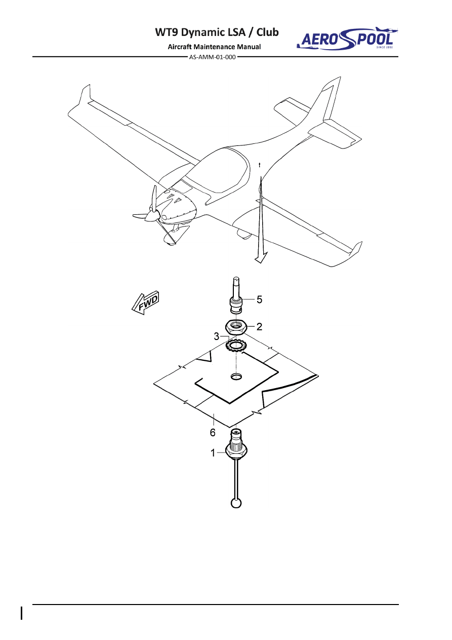
–  Transponder antenna 

–  Coaxial cable 

–  Antenna nut 

For information: 

–  Serrated locking washer 

–  Fuselage bottom part 

Fig. 34-13  XPDR Antenna Removal / Installation 


DEPENDENT POSITION DETERMINING   


NAVIGATION 

E. 

SV-GPS-250 antenna 

Type of maintenance: 

Line 

Personnel qualification: 

Independent  certifying  staff  qualified  in  accordance 


with Part-66 or higher. 

Recommended tools, materials, persons and documentation: 

ITEM 

QUANTITY 

Philips screwdriver 

1 pc 

Cable ties 2.6 

AR 

Persons 

Tab. 34-11 Recommended tools, materials, persons and documentation 

(1)  SV-GPS-250 antenna removal: 

a) 

Set 

MASTER SWITCH

 to 

OFF

 position. 

b) 

Remove the instrument panel cover (Chapter 39-10). 

c) 

Disconnect the connector of cable (2, Fig. 34-14) from the display. 

d) 

Remove all cable ties on length of cable (2). 

e) 

Unscrew  the  bolts  (3),  remove  washers  (6),  nuts  (7)  and  remove  
the antenna (1). 

(2)  SV-GPS-250 antenna installation: 

a) 

Put  the  antenna  (1,  Fig.  34-14)  to  the  bracket  (8)  and  fasten  it  
by means of the bolts (3), washers (6) and nuts (7). 

b) 

Attach cable (2) by using cable ties. 

c) 

Connect the connector of cable (2) to the display. 

d) 

Install the instrument panel cover (Chapter 39-10). 

e) 

Set 

MASTER  SWITCH

  to

  ON

  position  and  carry  out  an  operational 

test.


Effectivity:

 ALL 

12. 06 2020


NAVIGATION 


–  SV-GPS-250 antenna 

–  Washer 6 x 12 x 0.5 

–  Cable 

–  Nut M4 

–  Bolt M4 x 25 (4 pcs) 

For information: 

–  TRX / AT-1 GPS antenna 

–  Bracket 

–  Cable 

–  Bracket 

Fig. 34-14  SV-GPS-250 and TRX / AT-1 GPS Antennas Removal / Installation 


DEPENDENT POSITION DETERMINING   


NAVIGATION 

F. 

TRX / AT-1 GPS antenna 

Type of maintenance: 

Line 

Personnel qualification: 

Independent  certifying  staff  qualified  in  accordance 


with Part-66 or higher. 

Recommended tools, materials, persons and documentation: 

ITEM 

QUANTITY 

Knife 

1 pc 

Double side tape 

AR 

Cable ties 2.6 

AR 

Persons 

Tab. 34-12 Recommended tools, materials, persons and documentation 

(1)  TRX / AT-1 GPS antenna removal: 

a) 

Set 

MASTER SWITCH

 to 

OFF

 position. 

b) 

Remove the instrument panel cover (Chapter 39-10). 

c) 

Disconnect the connector of cable (5, Fig. 34-14) from the TRX unit. 

d) 

Remove all cable ties on length of cable (5). 

e) 

Using knife, carefully remove the antenna (4). 

(2)  TRX / AT-1 GPS antenna installation: 

a) 

Remove all remains of tape from antenna (4, Fig. 34-14) and bracket 
(7). 

b) 

Glue new tape on the antenna (4) and put it on the bracket (7). 

c) 

Attach cable (5) by using cable ties. 

d) 

Connect the connector (5) to the TRX unit. 

e) 

Install the instrument panel cover (Chapter 39-10). 

f) 

Set 

MASTER  SWITCH 

to 

ON 

position  and  carry  out  an  operational 

test. 


Effectivity:

 ALL 

12. 06. 2020


NAVIGATION 


G. 

GA 35 GPS antenna 

Type of maintenance: 

Line 

Personnel qualification: 

Independent certifying staff qualified in accordance 


with Part-66 or higher. 

Recommended tools, materials, persons and documentation: 

ITEM 

QUANTITY 

Philips screwdriver 

1 pc 

Wrench 7 

1 pc 

Knife 

1 pc 

Persons 

Tab. 34-13 Recommended tools, materials, persons and documentation 

(1)  GA 35 GPS antenna removal: 

a) 

Set 

MASTER SWITCH

 to 

OFF

 position. 

b) 

Remove the instrument panel cover (Chapter 39-10). 

c) 

Remove the EPS cover (Chapter 06-00). 

d) 

Disconnect the connector (5, Fig. 34-15) from the GPS antenna. 

e) 

Unscrew the nuts (4), remove washers (7, 8), remove the ground 
wire (2) and remove the screws (3). 

f) 

Pull out the metal plate (6) and carefully pull out GPS antenna (1) 
from the fuselage using a knife. 

g) 

Install the protective cover on the antenna connector. 

(2)  GA 35 GPS antenna installation: 

a) 

Put the antenna (1, Fig. 34-15) to correct position on top of fuselage. 

b) 

Attach the antenna using the screws (3), metal plate (6), washers  
(7, 8), ground wire (2) and nuts (4). 

c) 

Connect the connector (5) to the GPS antenna. 

d) 

Apply the white silicone around the antenna to seal it. 

e) 

Install the EPS cover (Chapter 06-00). 

f) 

Install the instrument panel cover (Chapter 39-10). 

g) 

Set 

MASTER SWITCH 

to 

ON 

position and carry out an operational 

test. 


DEPENDENT POSITION DETERMINING   


NAVIGATION 


–  GPS GA 35 antenna 

–  Connector 

–  Ground wire 

–  Metal plate 

–  Bolt M4 x 30 

–  Washer 4 x 12 x 1 

–  Nut M4 

–  Washer 4 x 9 x 0.7 

Fig. 34-15  GPS GA 35 Antenna Removal / Installation 


CONTENTS 


INSTRUMENT AND 

CONTROL PANELS 


39  INSTRUMENT AND 

CONTROL PANELS 

CONTENTS 

GENERAL ......................................................................... 3


1.


INTRODUCTION ....................................................................... 3


39-10


INSTRUMENT AND CONTROL PANELS......................... 5


1.


DESCRIPTION .......................................................................... 5


A.


WT9 Dynamic LSA / Club Instrument panel ...................... 6


B.


WT9 Dynamic LSA / Club Instrument panel (towing version)
 .......................................................................................... 9


2.


MAINTENANCE PRACTICES ................................................. 13


A.


Instrument panel cover .................................................... 13


B.


Instrument panel .............................................................. 15


C.


12 V socket ...................................................................... 17


D.


Circuit breakers KLIXON ................................................. 19


E.


Circuit breakers ETA 106-P10 ......................................... 21


F.


Switches .......................................................................... 23


G.


Control / warning lamp .................................................... 25


H.


Test button ...................................................................... 27


I.


Airspeed indicator, altimeter ............................................ 28


J.


Vertical speed indicator ................................................... 31


K.


Standby RPM indicator .................................................... 33


L.


Propeller regulator PR1-P ............................................... 35


M.


Flight hours counter ......................................................... 37


N.


Standby bank indicator .................................................... 39


O.


SV-D1000 display ............................................................ 41


P.


PM3000 intercom ............................................................ 45


Q.


Radio Garmin GNC 255A NAV/COMM ........................... 47


GENERAL 


INSTRUMENT AND 

CONTROL PANELS 


39-00  GENERAL 

1.  INTRODUCTION 

The instrument panel is arranged primarily for use by the pilot in the left seat; however, 
it can be viewed from the co-pilot in the right seat. Primary flight display and warning 
and  control  lamps  are  located  on  the  left  side  of  the  panel  and  engine  monitoring 
system is located on the right side of the instrument panel. 


INSTRUMENT AND CONTROL PANELS  


INSTRUMENT AND 

CONTROL PANELS 


39-10  INSTRUMENT AND CONTROL PANELS 

1.  DESCRIPTION 

Instrument panel is made of glass/carbon fabric laminate and is attached to the central 
tunnel and  both  sides of  fuselage.  In the middle  of  top  edge  is  the panel  supported  
with composite stiffener. The instrument panel is covered with glass laminate cover. 
The  cover  overlaps  the  instrument  panel  to  limits  undesirable  reflections  
on instruments displays. The panel is divided into three sections: left, centre and right. 
Under the instrument panels, on both left and right side, are located remote controls 
for position adjustment of rudder pedals.  

Depending on the  installed equipment, there are available two layouts of instrument 
panel.  For  basic  instrument  panel  layouts  see  1.A.  (Fig.  39-1),  for  instrument  panel 
layout with installed towing equipment see 1.(Fig. 39-2)


Effectivity:

 ALL 

12. 06. 2020


INSTRUMENT AND 
CONTROL PANELS 
 

A. 

WT9 Dynamic LSA / Club Instrument panel 


Layout valid from S/N 17001 to 20005 inclusive 


Layout valid from S/N 21001 

Fig. 39-1  Instrument Panel Layout (page 1 of 2) 


INSTRUMENT AND CONTROL PANELS  


INSTRUMENT AND 

CONTROL PANELS 


–  PFD Dynon SkyView SV-D1000 

22 

–  USB Connector (RH-D1000) 

–  MFD Dynon SkyView SV-D1000 

23 

–  Standby fuel pressure indicator 

–  Standby altimeter 

24 

–  Flying hours counter 

–  Standby airspeed indicator  

25 

–  Pedal’s adjustment remote control handle 

–  USB Connector (LH-D1000) 

26 

–  12V/10A Power socket 

– 

FUEL PUMP

 control lamp 

27 

–  Standby bank indicator 

– 

STALL

 warning lamp 

28 

– 

AVIONICS

 switch 

– 

LH FUEL RES.

 warning lamp 

29 

– 

NAV / ACL

 switch 

– 

RH FUEL RES.

 warning lamp 

30 

– 

LAND

 switch 

10 

– 

EMS

 warning lamp 

31 

– 

FUEL PUMP

 switch 

11 

– 

OIL PRESS.

 warning lamp 

32 

– 

IGNITION

 switches 

12 

– 

TEST 

button 

33 

– 

THROTTLE

 control 

13 

– 

CHARGE

 warning lamp 

34 

– 

CARBUR. PREHEATING

 handle 

14 

–  Intercom 

35 

–  Fuel selector valve 

15 

–  Magnetic compass 

36 

– 

MASTER SWITCH


16 

–  Standby variometer 

37 

–  Keyed ignition switch 

17 

–  Standby RPM indicator 

38 

– 

RESCUE SYSTEM

 activating 


handle 

18 

–  NAV / COMM radio 

39 

– 

CABIN HEATING

 control 

19 

–  Transponder 

40 

– 

CABIN VENTILATION

 control 

20 

–  ELT remote control 

41 

– 

CHOKE

 control 

21 

–  Engine Hours Counter 

42 

–  Circuit breakers 

Fig. 39-1  Model Instrument Panel Layout (page 2 of 2) 


Effectivity:

 ALL 

12. 06. 2020


INSTRUMENT AND 
CONTROL PANELS 
 

Left section of instrument panel: 

Installed  are:  standby  airspeed  indicator  Winter  7FMS511  (or  7FMS513),  altimeter 
Winter 4FGH40 and bank indicator Winter QMII.  

Primary  Flight  Display  (PFD)  Dynon  SkyView  SV-D1000  is  installed  in  the  middle  
of  left  section.  This  instrument  also  can  display  data  of  Engine  Monitoring  System 
(EMS) and MAP data. 

Under the PFD, in the lower right corner of the left section are located the following 
switches: 

AVIONICS

NAV / ACL

 (navigation and anti-collision lights), 

LAND

 (landing 

lights) and 

FUEL PUMP

Above  the  PFD  is  located  a  row of  control and  warning  lamps  as  follows  (with  their 
meaning): 

FUEL PUMP   

activation of the auxiliary electric fuel pump 

STALL 


activation of the stall warning system 

LH FUEL RES.


fuel quantity in the left tank is less than 16 liters 

RH FUEL RES.


fuel quantity in the right tank is less than 16 liters 

EMS


exceeding of the engine limit parameters 

OIL PRESS.


oil pressure is less than 2 bar / 29 psi 

CHARGE


voltage is less than approximately 12.5 volts

.


Control and warning lamps function can be verified by pressing of the 

TEST

 button. 

In the left lower corner is located 12 V / 10 A power socket. 


Central section of instrument panel: 

In  bottom  section  are  installed: 

IGNITION

  switches,  starter  key  and 

MASTER 

SWITCH

.  There  are also  installed  transponder  Garmin  GTX  328  or  GTX  335,  radio 

Garmin  GNC  255A,  intercom  PM3000,  standby  variometer  5StVM  10  and  standby 
RPM indicator ROAD IF61.2B35.2301. 

Sticker with registration marks is also placed in this section. 

At  the  top  of  centre  section  there  is  installed  magnetic  compass  Airpath  C-2400P  
on the glare shield. 


Right section of instrument panel: 

Multifunction Flight Display (MFD) Dynon Skyview SV-D1000 is installed in the middle 
of right section. This instrument displays data of Engine Monitoring System (EMS). 

On the right part are installed: standby fuel pressure indicator Skydrive FP-912/10 and 
flying hours counter Winter FSMZ. 

Circuit breakers are placed in a row at the lower edge of right section and on the right 
side of right section (list of circuit breakers with values is in Chapter 24-60). In the right 
lower corner is 12 V / 10 A power socket. 

Remote  control  of  the  Emergency  Locator  Transmitter  (ELT)  and  Engine  Hours 
Counter Hobbs are placed in the left upper area of right section. 


INSTRUMENT AND CONTROL PANELS  


INSTRUMENT AND 

CONTROL PANELS 


Central console: 

Vertical section contains throttle control, rescue system actuator, carburetor preheating 
control, cockpit heating and ventilation control handles, fuel selector valve and choke 
control. 

Pedestal panel between pilot and co-pilot is equipped with flaps control, pitch and roll 
trim switches and brake lever (see Chapter 27-50). 


Instrument Panel Cover: 

Instrument  panel  cover  (1,  Fig.  39-3)  is  made  of  glass  laminate.  It  is  attached  
to the fuselage with screws. On the top of  the cover is attached magnetic compass 
(Chapter  39-10,  see  2.S.),  on  the  bottom  part  are  attached  ADS-B  and  FLARM 
antennas (Chapter 34-40). 

B. 

WT9 Dynamic LSA / Club Instrument panel (towing version) 


Fig. 39-2  Instrument Panel Layout (Towing Version) (page 1 of 2) 


Effectivity:

 ALL 

12. 06. 2020


INSTRUMENT AND 
CONTROL PANELS 
 

–  PFD Dynon SkyView SV-D1000 

23 

–  Standby fuel pressure indicator 

–  MFD Dynon SkyView SV-D1000 

24 

–  Flying hours counter 

–  Standby altimeter 

25 

–  Pedal’s adjustment remote control handle 

–  Standby airspeed indicator  

26 

–  12V/10A Power socket 

–  USB Connector (LH-D1000) 

27 

–  Standby bank indicator 

– 

FUEL PUMP

 control lamp 

28 

– 

AVIONICS

 switch 

– 

STALL

 warning lamp 

29 

– 

NAV / ACL

 switch 

– 

LH FUEL RES.

 warning lamp 

30 

– 

LAND

 switch 

– 

RH FUEL RES.

 warning lamp 

31 

– 

FUEL PUMP

 switch 

10 

– 

EMS

 warning lamp 

32 

– 

IGNITION

 switches 

11 

– 

OIL PRESS.

 warning lamp 

33 

– 

THROTTLE

 control 

12 

– 

TEST 

button 

34 

– 

CARBUR. PREHEATING

 handle 

13 

– 

CHARGE

 warning lamp 

35 

–  Fuel selector valve 

14 

–  Intercom 

36 

– 

MASTER SWITCH


15 

–  Magnetic compass 

37 

–  Keyed ignition switch 

16 

–  Standby variometer 

38 

– 

RESCUE SYSTEM

 activating 


handle 

17 

–  Propeller regulator 

39 

– 

CABIN HEATING

 control 

18 

–  NAV / COMM radio 

40 

– 

CABIN VENTILATION

 control 

19 

–  Transponder 

41 

– 

CHOKE

 control 

20 

–  ELT remote control 

42 

–  Circuit breakers 

21 

–  Engine Hours Counter 

43 

– 

CAMERA

 switch 

22 

–  USB Connector (RH-D1000) 

44 

– 

TOW RELEASE

 handle 

Fig. 39-2  Instrument Panel Layout (Towing Version) (page 2 of 2) 


INSTRUMENT AND CONTROL PANELS  


INSTRUMENT AND 

CONTROL PANELS 


Left section of instrument panel: 

Installed  are:  standby  airspeed  indicator  Winter  7FMS511  (or  7FMS513),  altimeter 
Winter 4FGH40 and bank indicator Winter QMII. 

Primary  Flight  Display  (PFD)  Dynon  SkyView  SV-D1000  is  installed  in  the  middle  
of  left  section.  This  instrument  also  can  displays  data  of  Engine  Monitoring  System 
(EMS) and MAP data. 

Under the PFD, in the lower right corner of the left section are located the following 
switches: 

AVIONICS

NAV / ACL

 (navigation and anti-collision lights), 

LAND

 (landing 

lights), 

FUEL PUMP

 and 

CAMERA

Above  the  PFD  is  located  a  row of  control and  warning  lamps  as  follows  (with  their 
meaning): 

FUEL PUMP   

activation of the auxiliary electric fuel pump 

STALL 


activation of the stall warning system 

LH FUEL RES.


fuel quantity in the left tank is less than 16 liters 

RH FUEL RES.


fuel quantity in the right tank is less than 16 liters 

EMS


exceeding of the engine limit parameters 

OIL PRESS.


oil pressure is less than 2 bar / 29 psi 

CHARGE


voltage is less than approximately 12.5 volts

.


Control and warning lamps function can be verified by pressing of the 

TEST

 button. 

In the left lower corner is located 12 V / 10 A power socket. 


Central section of instrument panel: 

In  bottom  section  are  installed: 

IGNITION

  switches,  starter  key  and 

MASTER 

SWITCH

.  There  are also  installed  transponder  Garmin  GTX  328  or  GTX  335,  radio 

Garmin  GNC  255A,  intercom  PM3000,  standby  variometer  5StVM  10  and  Flybox 
Propeller regulator PR1-P. Sticker with registration marks is also placed in this section. 

At  the  top  of  centre  section  there  is  installed  magnetic  compass  Airpath  C-2400P  
on the glare shield. 


Right section of instrument panel: 

Multifunction Flight Display (MFD) Dynon Skyview SV-D1000 is installed in the middle 
of right section. This instrument displays data of Engine Monitoring System (EMS). 

On the right part are installed: standby fuel pressure indicator Skydrive FP-912/10 and 
flying hours counter Winter FSMZ. 

Circuit breakers are placed in a row at the lower edge of right section and on the right 
side of right section (list of circuit breakers with values is in Chapter 24-60). In the right 
lower corner is 12 V / 10 A power socket. 

Remote  control  of  the  Emergency  Locator  Transmitter  (ELT)  and  Engine  Hours 
Counter Hobbs are placed in the left upper area of right section.  


Content      ..     27      28      29      30     ..