WT9 Dynamic LSA. AIRCRAFT MAINTENANCE MANUAL (AS-AMM-01-000, 22. 05. 2017) - page 28
 

  Index      Manuals     WT9 Dynamic LSA. AIRCRAFT MAINTENANCE MANUAL (AS-AMM-01-000, 22. 05. 2017)


Search            copyright infringement  


Content      ..     26      27      28      29     ..


WT9 Dynamic LSA. AIRCRAFT MAINTENANCE MANUAL (AS-AMM-01-000, 22. 05. 2017) - page 28


Effectivity:

 ALL 

29. 01. 2020


NAVIGATION 


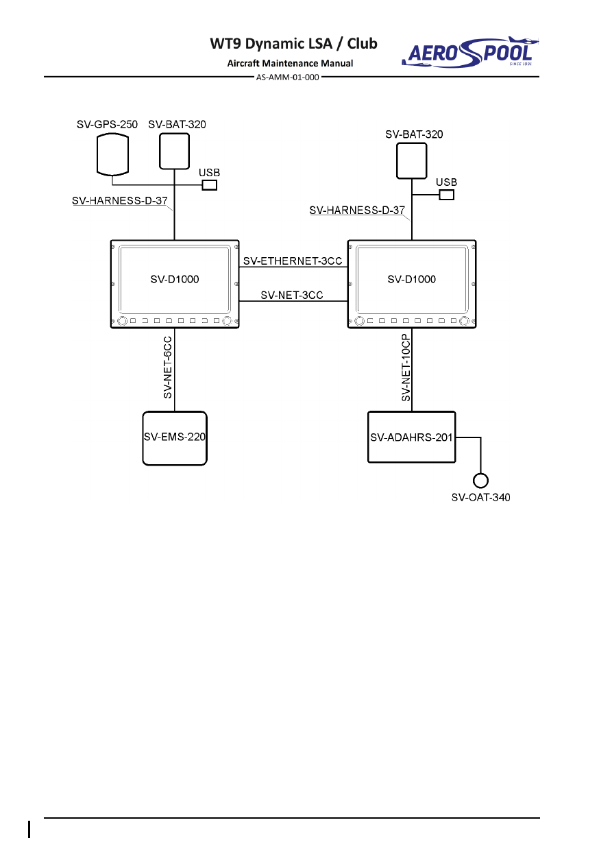
Fig. 34-8  Dynon Skyview System Scheme 


ATTITUDE AND DIRECTION 


Page 34-25 


NAVIGATION 

2. 

TROUBLESHOOTING 


TROUBLE 

POSSIBLE CAUSE 

REMEDY 

Pitot static system 

Excessive card error. 

Compass not properly 
compensated. 

Compensate instrument. 

External magnetic 
interference. 

Locate magnetic 
interference and eliminate 
if possible. 

Excessive card oscillation. 

Insufficient fluid. 

Replace instrument. 

Card sluggish. 

Weak card magnet. 

Replace instrument. 

Excessive pivot friction or 
broken jewel. 

Replace instrument. 

Liquid leakage. 

Loose bezel bolts. 

Replace instrument. 

Broken cover glass. 

Replace instrument. 

Defective sealing gaskets.  Replace instrument. 

Card sticks. 

Altitude compensating 
diaphragm collapsed. 

Replace instrument. 

Card does not move when 
compensating bolts are 
turned. 

Gears that turn 
compensating magnets 
stripped. 

Replace instrument. 

Excessive drift in either 
direction. 

Excessive vibration. 

Tighten mounting bolts. 


Effectivity:

 ALL 

29. 01. 2020


NAVIGATION 


3. 

MAINTENANCE PRACTICES 

A. 

SV-D1000 display 

For removal / installation procedures refer to Chapter 39-10. 

B. 

Magnetic compass 

For removal / installation procedures refer to Chapter 39-10. 

C. 

Standby bank indicator 

For removal / installation procedures refer to Chapter 39-10. 


INDEPENDENT POSITION DETERMINING 


NAVIGATION 

34-40  INDEPENDENT POSITION DETERMINING 

1.  DESCRIPTION 

This chapter covers that portion of the system that provides information to determine 
position from sources that are mainly independent of ground installations. This includes 
the GPS and TRX-1500 / AT-1 traffic sensor. 

GPS  signals  are  received by  an  SV-GPS-250  antenna  mounted  inside  the  fuselage 
under  the  left  part  of  the  instrument  panel  cover  (Fig.  34-14),  which  is  connected  
to the SkyView system. 

GPS  antenna  GA  35  for  GTX  335  is  mounted  outside  on  the  top  of  front  fuselage  
on the left side. 

The  TRX-1500  /  AT-1  traffic  sensor  combines  a  high-performance  ADS-B  receiver  
with an integral FLARM module. FLARM is a very popular collision avoidance system 
for general aviation and gliders, which monitors airspace around aircraft. GPS signals 
are  received  by  a  TRX  /  AT-1  GPS  antenna  mounted  inside  the  fuselage  under  
the right part of the instrument panel cover (Fig. 34-14). 

FLARM and ADS-B antennas are attached on the bottom side of the instrument panel 
cover (Fig. 34-9)

FLARM antenna AV-75 for AT-1 is mounted outside on the bottom of central section 
fuselage. 

NOTE 

Refer to TRX-1500 ADS-B / FLARM Traffic sensor, User Manual Installation 
Manual, Revision: 1.0a, 31 Jan. 2012 or later for additional information. 

Refer  to  GARMIN  GA  35,  Antenna  Installation  Instructions,  Revision:  B,  
P/N: 190-00848-00, March 2008 or later for additional information. 

Refer to AT-1 Traffic sensor, Installation Manual, Revision: 2.0, 25 10. 2018 
or later for additional information. 


Effectivity:

 ALL 

12. 06. 2020


NAVIGATION 


2.  MAINTENANCE PRACTICES 

A. 

FLARM, ADS-B Antenna 

Type of maintenance: 

Line 

Personnel qualification: 

Independent  certifying  staff  qualified  in  accordance 


with Part-66 or higher. 

Recommended tools, materials, persons and documentation: 

ITEM 

QUANTITY 

Persons 

Cable ties 2.6 

AR 

Tab. 34-6 Recommended tools, materials, persons and documentation 

NOTE 

Removal / installation is the same for the FLARM, ADS-B antenna. 

(1)  FLARM / ADS-B antenna removal: 

a) 

Set 

MASTER SWITCH

 to 

OFF

 position. 

b) 

Remove and carefully lift the instrument panel cover (Chapter 39-10). 

c) 

Disconnect the connector (3 / 4, Fig. 34-10) from the unit. 

d) 

Remove ADS-B (1, Fig. 34-9) / FLARM (3) antenna. 

e) 

Remove all cable ties on length of cable (2 / 4). 

(2)  FLARM / ADS-B antenna installation: 

a) 

Install ADS-B (1,  Fig. 34-9) /  FLARM (3) antenna to the appropriate 
bracket (5 / 6). 

b) 

Attach cables (2 / 4) by using cable ties. 

c) 

Connect the connector (3 / 4, Fig. 34-10) to the unit (1). 

d) 

Install the instrument panel cover (1) on the fuselage (Chapter 39-10). 

e) 

Set 

MASTER  SWITCH

  to

  ON

  position  and  carry  out  an  operational 

test. 


INDEPENDENT POSITION DETERMINING 


NAVIGATION 


–  ADS-B antenna 

–  Bracket 

–  Cable 

–  Bracket 

–  FLARM antenna 

–  Instrument panel cover 

–  Cable 


Fig. 34-9  FLARM / ADS-B Antenna Removal / Installation 


Effectivity:

 ALL 

12. 06. 2020


NAVIGATION 


B. 

TRX-1500 traffic sensor 

Type of maintenance: 

Line 

Personnel qualification: 

Independent certifying staff qualified in accordance 


with Part-66 or higher. 

Recommended tools, materials, persons and documentation: 

ITEM 

QUANTITY 

Philips screwdriver 

1 pc 

Persons 

Tab. 34-7 Recommended tools, materials, persons and documentation 

(1)  TRX-1500 traffic sensor removal: 

a) 

Set 

MASTER SWITCH

 to 

OFF

 position 

b) 

Remove the instrument panel cover (Chapter 39-10). 

c) 

Disconnect the connectors (2; 3; 4; 5, Fig. 34-10) from the unit (1). 

d) 

Remove the mounting bolts (6) and washers (7; 8). 

e) 

Remove the unit (1) from the bracket. 

(2)  TRX-1500 traffic sensor installation: 

a) 

Put the unit (1, Fig. 34-10) in position on the bracket (9). 

b) 

Hold the unit and attach it with bolts (6) and washers (7; 8). 

c) 

Connect the connectors (2; 3; 4; 5) to the unit. 

d) 

Install the instrument panel cover (Chapter 39-10). 

e) 

Set 

MASTER  SWITCH 

to 

ON

  position  and  carry  out  an  operational 

test. 

(3)  TRX-1500 traffic sensor adjustment / test: 

If  the  integral  FLARM  module  requires  adjustment  or  test,  refer  
to  TRX-1500  ADS-B  /  FLARM  Traffic  Sensor  User  Manual  Installation 
Manual, Revision: 1.0a, 31 Jan. 2012 or later for additional information


INDEPENDENT POSITION DETERMINING 


NAVIGATION 


–  TRX-1500 unit 

–  Bolt M4 x 12 

–  Main connector 

–  Washer 4.3 x 9 x 0.8 

–  ADS-B antenna connector 

–  Spring washer 4.3 

–  FLARM antenna connector 

For information: 

–  GPS antenna connector 

–  Bracket 

Fig. 34-10  TRX-1500 Traffic Sensor a Removal / Installation 


Effectivity:

 ALL 

12. 06. 2020


NAVIGATION 


C. 

AT-1 traffic sensor 

Type of maintenance: 

Line 

Personnel qualification: 

Independent certifying staff qualified in accordance 


with Part-66 or higher. 

Recommended tools, materials, persons and documentation: 

ITEM 

QUANTITY 

Philips screwdriver 

1 pc 

Wrench 7 

1 pc 

Persons 

Tab. 34-8 Recommended tools, materials, persons and documentation 

(1)  AT-1 traffic sensor removal: 

a) 

Set 

MASTER SWITCH

 to 

OFF

 position. 

b) 

Remove the instrument panel cover (Chapter 39-10). 

c) 

Disconnect the connectors (2; 3; 4; 5, 10, Fig. 34-11) from the unit (1). 

d) 

Remove the unit (1) from mounting tray (9). 

e) 

Remove  the mounting  bolts  (6),  washers  (7),  nuts  (8)  and  mounting 
tray (9) from the bracket (11). 

(2)  AT-1 traffic sensor installation: 

a) 

Put  the  mounting  tray (9,  Fig.  34-11)  in  position  on  the bracket  (11) 
and attach it using bolts (6), washers (7) and nuts (8). 

b) 

Insert the unit (1) into mounting tray (9) in correct position. 

c) 

Connect the connectors (2; 3; 4; 5, 10) to the unit (1). 

d) 

Install the instrument panel cover (Chapter 39-10). 

e) 

Set 

MASTER  SWITCH 

to 

ON

  position  and  carry  out  an  operational 

test. 

(3)  AT-1 traffic sensor adjustment / test: 

If  the  integral  FLARM  module  requires  adjustment  or  test,  refer  
to  AT-1  Traffic  Sensor  Installation  Manual,  Revision:  2.0,  25  10.  2018  
or later for additional information 


INDEPENDENT POSITION DETERMINING 


NAVIGATION 


–  AT-1 unit 

–  Washer 4.3 x 9 x 0.8 

–  Main connector 

–  Self-locking nut M4 

–  ADS-B antenna connector 

–  Mounting tray 

–  FLARM A antenna connector 

10 

–  FLARM B antenna connector 

–  GPS antenna connector 

For information: 

–  Bolt M4 x 12 

11 

–  Bracket 

Fig. 34-11  AT-1 Traffic Sensor Removal / Installation 


Effectivity:

 ALL 

12. 06. 2020


NAVIGATION 


D. 

FLARM Antenna AV-75 

Type of maintenance: 

Line 

Personnel qualification: 

Independent  certifying  staff  qualified  in  accordance 


with Part-66 or higher. 

Recommended tools, materials, persons and documentation: 

ITEM 

QUANTITY 

Wrench 8/32 

1 pc 

Persons 

Tab. 34-9 Recommended tools, materials, persons and documentation 

(1)  FLARM AV-75 antenna removal: 

CAUTION 

DO  NOT  ACTIVATE  ELT  WHEN  REMOVING  THE  CENTRAL 
TUNNEL COVER. IT IS SENSITIVE FOR SHOCKS. 

a) 

Set 

MASTER SWITCH

 to 

OFF

 position. 

b) 

Remove cover on the top side of central tunnel (Chapter 06-00). 

c) 

Disconnect coaxial cable (5, Fig. 34-12) from antenna (1). 

d) 

Unscrew the nuts (7), remove washers (6, 4, 3), ground wire (2) and 
remove antenna (1) with rubber pad (8) from the fuselage. 

e) 

Install the protective cover on the antenna connector. 

(2)  FLARM AV-75 antenna installation: 

a) 

Remove the protective cover from the antenna connector. 

b) 

Insert  the  antenna  (1,  Fig.  34-12)  with  rubber  pad  (8)  into  the  hole  
in the fuselage in correct position. 

c) 

Put  the  washers  (3,  4,  6),  ground  wire  (2) on 

antenna’s screws and 

tighten the nuts (7). 

d) 

Connect the coaxial cable (5). 

e) 

Install central tunnel cover (Chapter 06-00). 

f) 

Set 

MASTER  SWITCH

  to

  ON

  position  and  carry  out  an  operational 

test. 


INDEPENDENT POSITION DETERMINING 


NAVIGATION 


–  Flarm AV-75 antenna 

–  Spring washer 5 

–  Ground wire 

–  Nut 8-32 

–  Washer 5.3 x 15 x 1,2 

–  Rubber pad 

–  Washer 4.3 x 9 x 0.7 

For information: 

–  Connector 

–  Aluminium tape 

Fig. 34-12  AV-75 Antenna Removal / Installation 


Effectivity:

 ALL 

12. 06. 2020


NAVIGATION 


E. 

VHF COMM antenna 

For removal / installation procedures refer to Chapter 23-10. 


DEPENDENT POSITION DETERMINING   


NAVIGATION 

34-50  DEPENDENT POSITION DETERMINING 

1.  DESCRIPTION 

This chapter covers that portion of the system which provides information to determine 
position  from  sources  which  are  mainly  dependent  on  ground  installations.  
This includes the GNC 255A NAV / COMM, Garmin GTX 328 328 or Garmin GTX 335 
Transponder system, and VOR/LOC antenna and transponder antenna. 

The  aircraft  is  equipped  with  Garmin  GNC  255A  NAV  /  COMM  device  
(Chapter 39-10). Garmin GNC 255A NAV / COMM consists of a transmitter / receiver 
for VHF communication (COM) and a receiver for navigation information (NAV). These 
are combined with operating controls in one unit. The COM section of the GNC 255A 
NAV  /  COMM  operates  in  the  aviation  voice  band,  from  118.000  to  136.975  MHz,  
in  25  kHz  steps  (default).  For  European  operations,  a  Com  radio  configuration  
of  8.33  kHz  steps  is  also  available.  The  NAV  section  operates  from  108  MHz  
to 117.95 MHz decoding both the VHF Omni Range and Localizer navigation signals. 
The  built-in  Glideslope  receiver  will  automatically  tune  the  corresponding  glideslope 
paired frequencies (328 MHz to 335 MHz) when the localizer is tuned. 

The Garmin GTX 328 panel mounted Mode S transponder is a radio transmitter and 
receiver  that  operates  on  radar  frequencies,  receiving  ground  radar  or  TCAS 
interrogations  at  1030  MHz  and  transmitting  a  coded  response  of  pulses  to  ground 
based  radar  on  a  frequency  of  1090  MHz.  The  GTX  328  is  equipped  with  IDENT 
capability that activates the Special Position Identification (SPI) pulse for 18 seconds. 
Mode S transmit/receive capability also requires 1090 MHz transmitting and 1030 MHz 
receiving for Mode S functions. 

In addition to displaying the code, reply symbol and mode of operation, the GTX 328 
screen  will  display  pressure  altitude,  and  timer  functions.  The  unit  also  features  
an altitude monitor, and flight timers. A voice or tone audio output announces altitude 
deviation, and count down timer expiration. 

The GTX 328 transponder (Chapter 39-10) is powered on by pressing the STBY, ALT 
or ON keys. After power on a start-up page will be displayed while the unit performs  
a  self-test. 

Refer  to  the  Garmin  GTX  328  Mode  S  transponder  Pilot’s  Guide,  

P/N  190-00420-03  (revision  A  or  later)  for  complete  descriptions  of  the  Garmin  
GTX 328 transponder. 

The Garmin GTX 335 panel mounted Mode S transponder is a radio transmitter and 
receiver  that  operates  on  radar  frequencies,  receiving  ground  radar  or  TCAS 
interrogations  at  1030  MHz  and  transmitting  a  coded  response  of  pulses  to  ground 
based  radar  on  a  frequency  of  1090  MHz.  The  GTX  335  is  equipped  with  IDENT 
capability that activates the Special Position Identification (SPI) pulse for 18 seconds. 
Mode S transmit/receive capability also requires 1090 MHz transmitting and 1030 MHz 
receiving for Mode S functions.  

The  transponder  also  features  the  1090  MHz  ADS-

B  “Out”  transmission  capability 

(using  precise  GPS-referenced  positioning  information),  which  enables  the  device  
to  automatically  output  more accurate and  more  useful  traffic  surveillance  to  ATC 

– 

including  aircraft  flight  ID,  position,  altitude,  velocity,  climb/descent  and  heading 
information. 


Effectivity:

 ALL 

12. 06. 2020


NAVIGATION 


In addition to displaying the code, reply symbol and mode of operation, the GTX 335 
screen  will  display  pressure  altitude,  and  timer  functions.  The  unit  also  features  
an altitude monitor, and flight timers. A voice or tone audio output announces altitude 
deviation, and count down timer expiration.  

The  GTX  335  transponder  is  powered  on  by  pressing  the  SBY,  ALT  or  ON  keys.  
After power on a start-up page will be displayed while the unit performs a self-test. 
Refer to the Garmin GTX 335 Mode S transponder Pilot’s Guide, P/N 190-01499-00 
(revision F or later) for complete descriptions of the Garmin GTX 335 transponder. 


DEPENDENT POSITION DETERMINING   


NAVIGATION 

2.  MAINTENANCE PRACTICES 

A. 

Garmin GNC 255A NAV/COMM 

For removal / installation procedures refer to Chapter 39-10. 

B. 

Garmin GTX 328 / GTX 335 transponder 

For removal / installation procedures refer to Chapter 39-10. 

C. 

VOR/LOC antenna 

To replace this antenna, contact the aircraft manufacturer. 

D. 

Transponder antenna 

Type of maintenance: 

Line 

Personnel qualification: 

Independent  certifying  staff  qualified  in  accordance 


with Part-66 or higher. 

Recommended tools, materials, persons and documentation: 

ITEM 

QUANTITY 

Wrench 19 

1 pc 

Persons 

Tab. 34-10 Recommended tools, materials, persons and documentation 

(3)  Transponder antenna removal: 

CAUTION 

DO  NOT  ACTIVATE  ELT  WHEN  REMOVING  COVER.  IT  IS 
SENSITIVE FOR SHOCKS. 

f) 

Set 

MASTER SWITCH

 to 

OFF

 position. 

g) 

Remove cover of rear central console (in baggage compartment). 

h) 

Disconnect coaxial cable (5, Fig. 34-13) from transponder antenna (1). 

i) 

Unscrew  the  nut  (2),  remove  washer  (3)  and  pull  out  transponder 
antenna from the fuselage bottom part (6). 

j) 

Install the protective cover on the antenna connector. 

(4)  Transponder antenna installation: 

g) 

Remove the protective cover from the antenna connector. 

h) 

Insert  the  antenna  (1,  Fig.  34-13)  with  the  gasket  ring  to  the  hole  
in the fuselage bottom part (6). 

i) 

Insert the washer (3), screw and tighten the nut (2). 

j) 

Connect coaxial cable (5). 

k) 

Refit top cover. 

l) 

Set 

MASTER  SWITCH

  to

  ON

  position  and  carry  out  an  operational 

test - refer to the Garmin GTX 328 Transponder Installation Manual, 
P/N 190-00420-04 (revision C or later) / Garmin GTX 335 Transponder 
Installation Manual, P/N 190-01499-02 (revision 9 or later).


Content      ..     26      27      28      29     ..