WT9 Dynamic LSA. AIRCRAFT MAINTENANCE MANUAL (AS-AMM-01-000, 22. 05. 2017) - page 26


  Index      Manuals     WT9 Dynamic LSA. AIRCRAFT MAINTENANCE MANUAL (AS-AMM-01-000, 22. 05. 2017)


Search            copyright infringement  


Content      ..     24      25      26      27     ..


WT9 Dynamic LSA. AIRCRAFT MAINTENANCE MANUAL (AS-AMM-01-000, 22. 05. 2017) - page 26


STEERING 


LANDING GEAR  


Fig. 32-26  Steering Push Rods Removal / Installation (page 1 of 2) 
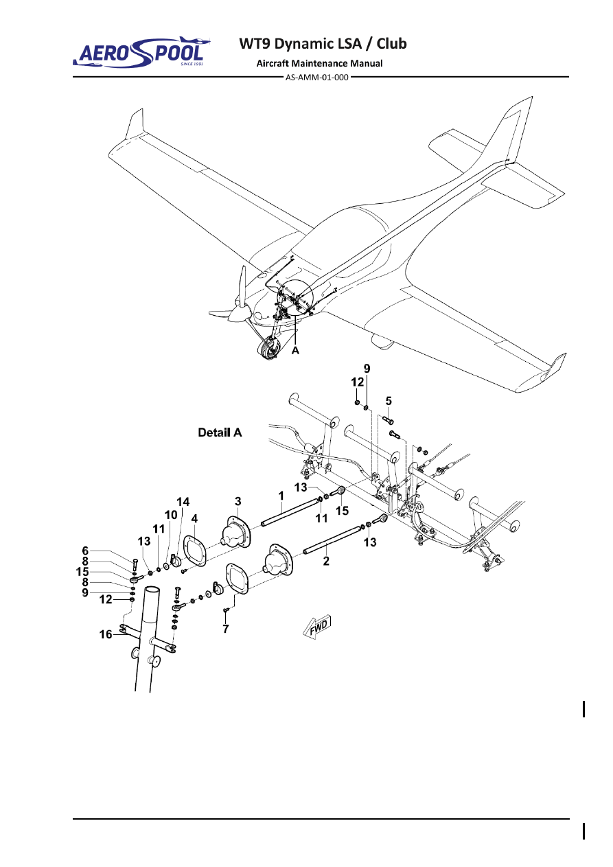


Effectivity:

 ALL 

12. 06. 2020


LANDING GEAR  


–  Push rod 

9 - 

Washer ø6.4 x 12 x 1.6 

–  Push rod 

10 - 

Washer ø6.4 x 30 x 1.6 

–  Sleeve 

11 - 

Serrated locking washer ø6.4 

–  Sleeve flange 

12 -  Self-locking nut M6 

–  Bolt M6 x 25 

13 -  Nut M6 

–  Bolt M6 x 28 

14 - 

Hose clamp ø16-27 

–  Bolt M3 x 10 

15 -  Swivel bearing 

8 - 

Washer ø6.4 x 10 x 1 

16 -  Nose landing gear leg 

Fig. 32-26  Steering Push Rods Removal / Installation (page 2 of 2) 


GENERAL 


LIGHTS 

33-00  GENERAL 

1.  INTRODUCTION 

This chapter describes the system and maintenance practices about the lighting on 
the airplane. 

Wiring diagram of the airplane lighting is described in the Airplane Wiring Manual 
(Doc. No. AS-AWM-01-000). 


Effectivity:

 ALL 

29. 01. 2020


LIGHTS 


2.  TROUBLESHOOTING 


TROUBLE 

POSSIBLE CAUSE 

REMEDY 

Both position lights do not 
operate. 

Circuit-breaker not set or 
defective. 

Set/replace the circuit-
breaker. 

Defective position light 
switch. 

Replace the switch. 

Defective wiring 

Carry out a continuity test 
of the wiring. 
Repair/replace defective 
wiring. Refer to Airplane 
Wiring Manual (Doc. No. 
AS-AWM-01-00) 

One position light does 
not operate. 

Defective wiring. 

Carry out a continuity test 
of the wiring. 
Repair/replace defective 
wiring. Refer to Airplane 
Wiring Manual (Doc. No. 
AS-AWM-01-00). 

Landing light not operate. 

Defective light. 

Replace the light. 

Circuit-breaker not set or 
defective. 

Set/replace the circuit-
breaker. 

Defective landing light 
switch. 

Replace the switch. 

Defective wiring. 

Carry out a continuity test 
of the wiring. 
Repair/replace defective 
wiring. Refer to Airplane 
Wiring Manual (Doc. No. 
AS-AWM-01-000). 

Loose connector next to 
the light. 

Connect the connector 
correctly. 

Decrease of light 
transmission (milky 
appearance) 

Degradation of light cover 
surface. 

Polish with a good 
automotive cleaner wax 
and/or a liquid polishing 
compound, apply coat of 
an automotive polish and 
polish with electric buffing 
machine. 


EXTERIOR LIGHTING 


LIGHTS 

33-40  EXTERIOR LIGHTING 

1.  DESCRIPTION 

This chapter contains information on servicing the anti-collision / position and landing 
lights. The anti-collision / position lights (1; 2, Fig. 33-1) are mounted to the outboard 
surface of each wing tip. The light assembly includes a LED strobe light with forward 
(red-left, green-right) and white position LED lights. 

The landing lights (3) are mounted to the bottom engine cowl. 

Landing lights are activated by switch labelled as 

LAND

 and they are connected 

through a circuit breaker to the master switch. Anti-collision / position lights are 
activated by switch labelled as 

ACL/NAV

 and they are connected through a circuit 

breaker to the master switch.  


Left anti-collision / position light (red) 

– 


Landing lights 


Right anti-collision / position light (green) 


Fig.  33-1  Exterior Lighting 


Effectivity:

 ALL 

29. 01. 2020


LIGHTS 


2.  MAINTENANCE PRACTICES 

A. 

Anti-collision / position lights 

Type of maintenance: 

Line 

Personnel qualification: 

Independent certifying staff qualified in accordance 


with Part-66 or higher. 

Recommended tools, materials, persons and documentation: 

ITEM 

QUANTITY 

Phillips screwdriver 

1 pc 

Knife 

1 pc 

Soldering gun 

1 pc 

Cable tie 2.6 

1 pc 

Shrink tube 

ø3.2 x 1.6 

AR 

Persons 

Tab. 33-1 Recommended tools, materials, persons and documentation 

WARNING 

ENGINE  IGNITION  MUST  BE  SWITCHED  OFF.  DISCONNECT 
NEGATIVE TERMINAL OF AIRPLANE BATTERY. 

(1)  Anti-collision / position light removal: 

(a)  Remove wing (Chapter 57-10). 

(b)  On wing root remove cable tie and push wires into the wing. 

(c)  On wing tip unscrew the screws (3, Fig. 33-2).  

(d)  Pull out light (1), remove the spiral hose (5), remove shrink tubes and 

unsolder the el. wires (4). 

(e)  Remove the light (1) and gasket (2). 

(2)  Anti-collision / position light installation: 

(a)  Shorten the wires (4, Fig. 33-2) of the light (1) to 100 mm. 

(b)  Pass the wires (4) through the appropriate hole in the gasket (2). 

(c)  Put the shrink tubes on wires, using soldering gun connect the wires, 

pull the shrink tubes over joints and apply heat to shrink them. 

(d)  Apply spiral hose (5) on joint. Set the position light (1) with the gasket 

(2) to the wing tip (6) and fasten it with screws (3). 

(e)  Install wing (Chapter 57-10). 

(f) 

Carry out an operational test. 

(3)  Anti-collision / position light polishing: 

(a)  Polish the lights after installation. 

NOTE 

Under no circumstances should any petroleum based product be 
used to clean the lights.


EXTERIOR LIGHTING 


LIGHTS 


–  Anti-collision / position light 

–  Wires and shrink tubes (3 + 1) 

–  Gasket 

–  Spiral hose ø3 

–  Screw M3 x 20 

–  Wing tip 

Fig.  33-2   Anti-collision / Position Light Removal / Installation


Effectivity:

 ALL 

04. 07. 2019


LIGHTS 


B. 

Landing lights 

Type of maintenance: 

Line 

Personnel qualification: 

Independent certifying staff qualified in accordance 


with Part-66 or higher. 

Recommended tools, materials, persons and documentation: 

ITEM 

QUANTITY 

Philips screwdriver 

1 pc 

Silicone 

AR 

Persons 

Tab. 33-2 Recommended tools, materials, persons and documentation 


WARNING 

ENGINE  IGNITION  MUST  BE  SWITCHED  OFF.  DISCONNECT 
NEGATIVE TERMINAL OF AIRPLANE BATTERY. 

NOTE 

Removal / installation is the same for both landing lights. 

(1)  Landing light removal: 

(a)  Make sure that the 

IGNITION 

switches are set to 

OFF

(b)  Remove the engine cowlings (Chapter 71-10). 

(c)  On bottom cowling disconnect connector (6, Fig. 33-3). 

(d)  Unscrew the screw (3), remove the washers (4; 5). 

(e)  Remove old silicone. 

(f) 

Pull out holder (2) and the landing light (1). 

(2)  Landing light installation: 

(a)  Clean all silicone residues. 

(b)  Make sure that the 

IGNITION 

switches are set to 

OFF

(c)  Place the holder (2, Fig. 33-3) with the light (1) to the bottom cowling 

(7). 

(d)  Insert the screw (3) with washers (4; 5) to the hole; tighten the screw. 

(e)  Connect the connector (6) to the light (1). 

(f) 

Install the engine cowlings (Chapter 71-10). 

(g)  Carry out an operational test.


EXTERIOR LIGHTING 


LIGHTS 


Landing light 


Washer 

ø4.3 x 12 x 1 


Holder 


Connector 


Screw M4 x 10 

For information: 


Spring washer 

ø4.3 


Bottom engine cowl 

Fig.  33-3  Landing Lights Removal / Installation


CONTENTS 


NAVIGATION 

34  NAVIGATION 

CONTENTS 

GENERAL ......................................................................... 3


1.


INTRODUCTION ....................................................................... 3


34-10


FLIGHT ENVIRONMENTAL DATA ................................... 5


1.


DESCRIPTION .......................................................................... 5


2.


TROUBLESHOOTING ............................................................... 7


3.


MAINTENANCE PRACTICES ................................................... 9


A.


Pitot-static probe ............................................................... 9


B.


SV-ADAHRS-200 module ................................................ 11


C.


Altitude encoders ACK-30 / GAE 12 ................................ 14


D.


Airspeed indicator ............................................................ 17


E.


Altimeter .......................................................................... 17


F.


Vertical speed indicator ................................................... 17


G.


Flight hours counter ......................................................... 17


H.


Stall warning transducer .................................................. 17


I.


Drain sumps .................................................................... 18


J.


Pitot-static system ........................................................... 20


34-20


ATTITUDE AND DIRECTION .......................................... 23


1.


DESCRIPTION ........................................................................ 23


2.


TROUBLESHOOTING ............................................................. 25


3.


MAINTENANCE PRACTICES ................................................. 26


A.


SV-D1000 display ............................................................ 26


B.


Magnetic compass .......................................................... 26


C.


Standby bank indicator .................................................... 26


Effectivity:

 ALL 

12. 06. 2020


NAVIGATION 


34-40


INDEPENDENT POSITION DETERMINING ................... 27


1.


DESCRIPTION ........................................................................ 27


2.


MAINTENANCE PRACTICES ................................................. 28


A.


FLARM, ADS-B Antenna ................................................ 28


B.


TRX-1500 traffic sensor .................................................. 30


C.


AT-1 traffic sensor .......................................................... 32


D.


FLARM Antenna AV-75 .................................................. 34


E.


VHF COMM antenna ...................................................... 36


34-50


DEPENDENT POSITION DETERMINING ....................... 37


1.


DESCRIPTION ........................................................................ 37


2.


MAINTENANCE PRACTICES ................................................. 39


A.


Garmin GNC 255A NAV/COMM ..................................... 39


B.


Garmin GTX 328 / GTX 335 transponder ....................... 39


C.


VOR/LOC antenna .......................................................... 39


D.


Transponder antenna...................................................... 39


E.


SV-GPS-250 antenna ..................................................... 41


F.


TRX / AT-1 GPS antenna ............................................... 43


G.


GA 35 GPS antenna ....................................................... 44


GENERAL 


NAVIGATION 

34-00  GENERAL 

1. 

INTRODUCTION 

This  chapter  describes  the  navigation  systems,  units,  and  components  which 
provide  aircraft  navigational  information.  Included  are  pitot-static,  compass, 
navigation  systems,  and  indicators.  The  subjects  to  be  covered  in  this  chapter 
are as follows: 

The  Flight  Environmental  Data/Pitot  Static  section  describes  systems  which 
sense  environmental  conditions  and  use  the  data  to  influence  navigation  
of the aircraft. This includes components that depend on the pitot-static system 
such  as  airspeed  indicator,  altimeter,  vertical  speed  indicator  and  ADAHRS 
module of the Dynon SkyView system. 

The  Attitude  and  Direction  section  describes  systems  which  use  magnetic, 
gyroscopic  and  inertia  forces.  This  includes  Dynon  SkyView  system  and  
the magnetic compass. 

The Independent Position Determining section describes systems which provide 
information  to  determine  position  from  sources  which  are  mainly  independent  
of  ground  installations.  This  includes  the  global  positioning  system  and  traffic 
sensor. 

The Dependent Position Determining  section describes systems which provide 
information  to  determine  position  from  sources  which  are  mainly  dependent  
on  ground  installations.  This  includes  systems  such  as  radio  navigational  aids 
and transponder. 

Wiring diagram of above mentioned equipment is described in the Aircraft Wiring 
Manual (Doc. No. AS-AWM-01-000). 


FLIGHT ENVIRONMENTAL DATA 


Page 34-5 


NAVIGATION 

34-10  FLIGHT ENVIRONMENTAL DATA 

1.  DESCRIPTION 

Arrangement and scheme of the pitot-static system is given on the Fig. 34-1. 

The  Pitot-static  probe (1)  is  installed  under  the  right  wing.  It  receives  total  pressure 
(hoses  marked  “P”),  static  pressure  (hoses  marked  “S”)  and  is  equipped  with  AOA 
sensing (hoses marked “A”). 
Pressure distribution to individual instruments on the airspeed indicator (3), altimeter 
(4), vertical speed indicator (5) expansion bottle (8), flight hours counter (6), altitude 
encoder  (7),  ADAHRS  module  (2)  and  stall  warning  transducer  (9)  (Chapter  31-50)  
in the cockpit is performed through the flexible plastic hoses. There are also three drain 
sumps (10) included in the pitot-static system. 

NOTE 

ADAHRS module is a part of the Dynon SkyView system, which is described  
in Chapter 34-20. 


Effectivity:

 ALL 

29. 01. 2020


NAVIGATION 


–  Pitot-static probe 

–  Flight hours counter 

–  ADAHRS module 

–  Altitude encoder 

–  Airspeed indicator 

–  Expansion bottle 

–  Altimeter 

–  Stall warning transducer 

–  Vertical speed indicator 

10 

–  Drain sumps 

Fig. 34-1  Pitot-Static System


FLIGHT ENVIRONMENTAL DATA 


Page 34-7 


NAVIGATION 

2. 

TROUBLESHOOTING 


TROUBLE 

POSSIBLE CAUSE 

REMEDY 

Pitot static system 

Low or sluggish airspeed 
indication. Normal 
altimeter and vertical 
speed indication. 

Pitot-static probe 
deformed. Leak or 
obstruction in total line. 

Repair or replace 
damaged component. 

Incorrect or sluggish 
response on all three 
pitot-static instruments. 

Leaks or obstruction in 
static line. 

Repair or replace line. 
Remove obstruction. 

Vertical speed indicator 

Pointer does not set on 
zero. 

Leaking or ruptured 
diaphragm. 

Substitute known-good 
indicator and check 
reading. Replace or repair 
instrument. 

Pointer fails to respond. 

Obstruction in static line. 

Check line for obstruction. 

Pointer oscillates or fails 
to respond. 

Leaks in static line. 

Check line for obstruction. 

Defective instrument. 

Replace or repair 
instrument. 

Excessive vibration 
caused by loose mounting 
bolts. 

Tighten mounting bolts. 

Excessive tube vibration. 

Tighten clamps and 
connections. 

Airspeed indicator 

Pointer fails to respond or 
indicates improperly. 

Leak in instrument case. 

Replace or repair 
instrument. 

Obstruction in total line. 

Check line for obstruction. 

Incorrect indication or 
pointer oscillates. 

Leak in total or static lines.  Repair or replace 

damaged lines. Tighten 
connections. 

Leaking or ruptured 
diaphragm. 

Substitute know-good 
indicator and check 
reading. Replace or repair 
instrument. 


Content      ..     24      25      26      27     ..