WT9 Dynamic LSA. AIRCRAFT MAINTENANCE MANUAL (AS-AMM-01-000, 22. 05. 2017) - page 25
 

  Index      Manuals     WT9 Dynamic LSA. AIRCRAFT MAINTENANCE MANUAL (AS-AMM-01-000, 22. 05. 2017)


Search            copyright infringement  


Content      ..     23      24      25      26     ..


WT9 Dynamic LSA. AIRCRAFT MAINTENANCE MANUAL (AS-AMM-01-000, 22. 05. 2017) - page 25


Effectivity:

 ALL 

04. 07. 2019


LANDING GEAR  


(2)  Nose wheel bearings replacement: 

(a)  Remove the wheel (Chapter 32-20).  

(b)  Deflate the tire to zero pressure. 

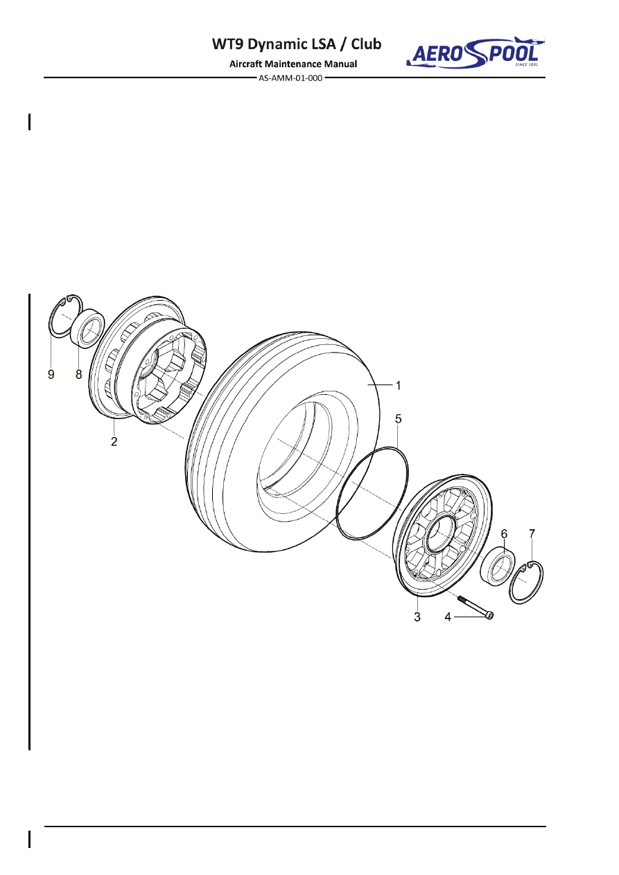
(c)  Separate the tire (1, Fig. 32-16) from the discs (2; 3). 

(d)  Unscrew the bolts (4) and disassemble the discs (2; 3). 

(e)  Remove the O-ring (5). 

(f) 

Use Circlip pliers to remove the circlips (7) and pull out the bearings 
(6). 

(g)  Slide in the new bearings (6) and secure with circlips (7). 

(h)  Install the tire (see 2.B.(1)). 


– Tire 

–  Bearing 

– Disc 1 

–  Circlip 

– Disc 2 

–  Bearing 

–  Allen bolt M8 x 70 

–  Circlip 

–  O-ring 


Fig. 32-16  Nose Wheel


WHEELS AND BRAKES 


LANDING GEAR  

C. 

Brake system 

Type of maintenance: 

Line 

Personnel qualification: 

Independent certifying staff qualified in accordance 


with Part-66 or higher. 

Recommended tools, materials, persons and documentation: 

ITEM 

QUANTITY 

Wrench 12 

1 pc 

Wrench 10 

1 pc 

Socket set 14 

1 pc 

Screwdriver 5 

1 pc 

Hex key 4 

1 pc 

Hex key 5 

1 pc 

Hex key 6 

1 pc 

Pliers 

1 pc 

Serrated locking washer 

ø6.4 mm 

2 pcs 

Copper gasket ring 

ø10 x 15 x 1.5 mm 

8 pcs 

Vaseline 

AR 

Sealing adhesive tape 

AR 

Persons 

Beringer documentation - Assembly instructions for hose and 
banjo fittings 


Tab. 32-12 Recommended tools, materials, persons and documentation 

(1)  Brake fluid reservoir removal: 

(a)  Drain the brake fluid from the brake system (see 2.C.(12)). 

(b)  Remove the left laminated seat (Chapter 25-10). 

(c)  On the reservoir holder (38, Fig. 32-17), loosen and remove the bolt 

(39), remove the washer (37) and nut (33). 

(d)  Remove the hose clamp (35) and remove the brake fluid reservoir (1).  


Effectivity:

 ALL 

12. 06. 2020


LANDING GEAR  


(2)  Brake fluid reservoir installation: 

(a)  Connect  the  fluid  reservoir  (1,  Fig.  32-17)  with  the  hose  (14)  and 

secure with the hose clamp (35). 

(b)  Install the fluid  reservoir (1) using the bolt (39) with the washer (37) 

and nut (33) on the reservoir holder (38). 

(c)  Fill the brake system with the brake fluid (see 2.C.(12)). 

(d)  Install the left laminated seat (Chapter 25-10). 

(e)  Carry out a test and check: 

  If all bolt connections are tight. 

  Tightness of the brake system. 

  That no foreign objects remain in the aircraft. 


WHEELS AND BRAKES 


LANDING GEAR  


–  Brake fluid reservoir  15 –  Brake hose R 

29 

–  Washer ø6.4x18x1.6 

–  Master cylinder  


assembly 

16 

–  Brake hose L 

30 

–  Washer ø5.3 x 15 x 1.2 

–  Master cylinder 

17 

–  Connecting brake hose 

31 

–  Washer ø6.4x12x1.6 

–  Swivel bearing 

18 

–  Holder ø75 

32 

–  Washer ø6.4x10x1.6 

–  Thread rod M6 x 40


19 

–  Holder ø70 

33 

–  Self-locking nut M6 

–  Fork with safety pin  20 –  Rubber 

34 

–  Self-locking nut M5 

–  Nut M6 

21 

–  Double banjo bolt M10  35 –  Hose clamp 

–  Serrated locking 


washer ø6.4 

22 

–  Banjo bolt M10 

36 

–  Spiral hose ø8 

–  Brake lever 

23 

–  Banjo fitting 

37 

–  Washer ø6.4x12x0.5 

10 

–  Pressure limiter 

24 

–  Copper gasket ring 


ø10 x 15 x 1.5 

38 

–  Reservoir holder 

11 

–  Caliper 

25 

–  Bolt M6x22 

39 

–  Bolt M6 x 12 

12 

–  Bracket 

26 

–  Bolt M6x25 

40 

–  Washer ø5.3 x 10 x 1 

13 

–  Bracket 

27 

–  Pin ø6 x 14 

41 

–  Split pin ø1.6 x 25 

14 

–  Hose 

28 

–  Allen bolt M6 x 16 

42 

–  Bleeding screw 

Fig. 32-17  Brake System Components Removal / Installation


Effectivity:

 ALL 

12. 06. 2020


LANDING GEAR  


(3)  Master cylinder assembly with brake lever removal: 

(a)  Drain the brake fluid from the brake system (see 2.C.(12)). 

(b)  Remove the pedestal panel (Chapter 27-50). 

(c)  Remove the left laminated seat (Chapter 25-10). 

(d)  Remove the elevator push rod in the central tunnel (Chapter 27-30). 

(e)  Remove the hose clamp (35, Fig. 32-17) and the hose (14). 

(f) 

Disconnect the brake hoses (15; 17) by removing the banjo bolt (21) 
and the gasket rings (24). 

(g)  Disconnect  the  brake  lever  (9)  from  the  fork  (6),  by  removing  

the safety pin. 

(h)  Remove  the  master  cylinder  assembly  (2)  with  the  bracket  (13),  

by removing the nuts (33), washers (29) and bolts (25). 

(i) 

Remove the bracket (13), by removing the nut (33), washers (31; 32) 
and bolt (26). 

(j) 

Disassemble the master cylinder assembly (2): 

  Unscrew the thread rod (5) with the fork (6). 

  Unscrew the swivel bearing (4). 

(k)  Remove  the  bracket  (12)  with  the  brake  lever  (9)  by  removing  

the nuts (33), washers (29) and bolts (25). 

(l) 

Remove the brake lever (9), by removing the split pin (41), washer (40) 
and bolt (27). 

(4)  Master cylinder assembly with brake lever installation: 

(a)  Connect the bracket (12, Fig. 32-17) with the brake lever (9), using bolt 

(27), washer (40) and split pin (41). 

CAUTION 

DO  NOT  FORGET  TO  LUBRICATE  THE  ROTATING  POINTS 
OF THE BRAKE LEVER. 

(b)  If necessary, assemble the master cylinder assembly (2): 

  Screw the swivel bearing (4) with the washer (8) almost fully in and 

tighten the lock nut (7). 

  Screw the thread rod (5) with the fork (6), washer (8) and lock nut 

(7) in; do not tighten yet. 

(c)  Connect the bracket (13) with the swivel bearing (4), using bolt (26), 

washers (31; 32) and nut (33). 

(d)  Install  the  whole  unit  (13;  2)  into  the  central tunnel  using bolts  (25), 

washers (29) and nuts (33). 

(e)  Enclose the central console and adjust the length of the thread rod (5) 

so that the brake lever is fully unloaded (front position) and the master 
cylinder (2) is not pushed. 

(f) 

Remove the central console, secure the fork (6) with the safety pin and 
tighten the lock nut (7).  


WHEELS AND BRAKES 


LANDING GEAR  

(g)  Assemble  the  brake  hoses  (15;  17)  with  banjo  fittings  (23)  

(see 2.C.(10)). 

(h)  Connect the brake hoses (15; 17) with the master cylinder (3), using 

banjo bolt (21) and gasket rings (24). 

CAUTION 

A  NEW  GASKET  RINGS  MUST  BE  INSTALLED  AT  EACH 
MASTER CYLINDER ASSEMBLY. 

(i) 

Connect  the  hose  (14)  with  the  master  cylinder  (3)  and  secure  
with hose clamp (35). 

(j) 

Fill the brake system with the brake fluid (see 2.C.(12)). 

(k)  Install the elevator push rod in the central tunnel (Chapter 27-30). 

(l) 

Install the left laminated seat (Chapter 25-10). 

(m)  Install the pedestal panel (Chapter 27-50). 

(n)  Carry out a test and check: 

  If all bolt connections are tight. 

  Tightness of the brake system. 

  That no foreign objects remain in the aircraft. 

(5)  Pressure limiter removal: 

(a)  Drain the brake fluid from the brake system (see 2.C.(12)).  

(b)  Remove the pedestal panel (Chapter 27-50). 

(c)  Remove the left laminated seat (Chapter 25-10). 

(d)  Disconnect the hoses (16; 17, Fig. 32-17) by removing the banjo bolt 

(21) and gasket rings (24). 

(e)  Remove  the  pressure  limiter  (10)  by  removing  the  nuts  (34)  and 

washers (30). 

(f) 

Remove the holders (18; 19) and rubbers (20). 

(6)  Pressure limiter installation: 

(a)  Install  the  rubbers  (20,  Fig.  32-17)  and  the  holders  (18;  19)  

on the pressure limiter (10). 

(b)  Install the pressure limiter (10) on the central tunnel under the left seat 

using washers (30) and nuts (34).  

(c)  Pass the connecting brake hose (17) through the holes in the central 

tunnel. 

(d)  Assemble the hoses (16; 17) with banjo fittings (23) (see 2.C.(10)). 

(e)  Connect the hoses (16; 17) with the pressure limiter (10) using banjo 

bolt (21) and gasket rings (24). 

(f) 

Fill the brake system with the brake fluid (see 2.C.(12)). 

(g)  Install the left laminated seat (Chapter 25-10).


Effectivity:

 ALL 

29. 01. 2020


LANDING GEAR  


(h)  Install the pedestal panel (Chapter 27-50). 

(i) 

Carry out a test and check: 

  If all bolt connections are tight. 

  Tightness of the brake system. 

  That no foreign objects remain in the aircraft. 

(7)  Brake caliper removal: 

(a)  Jack the aircraft and secure the tail (Chapter 07-10). 

(b)  Remove the main wheel (Chapter 32-10). 

(c)  On  the  main  landing  strut,  remove  the  sealing  adhesive  tape  and  

the spiral hose (36, Fig. 32-17). 

(d)  Disconnect the brake hose (16, 15) by removing the hose fitting (23), 

banjo bolt (22) and gasket rings (24). 

(e)  Remove the wheel axle with the brake caliper (11) (Chapter 32-10). 

(f) 

Unscrew  the  bolt  (28)  and  remove  the  brake  caliper  (11)  
from the wheel axle. 

(8)  Brake caliper installation: 

(a)  Install  the  brake  caliper  (11,  Fig.  32-17)  with  the  wheel  axle  

on the main landing gear leg (Chapter 32-10). 

CAUTION 

BLEEDING SCREW MUST DIRECT DOWN. 

(b)  Apply Loctite 243 on the bolt (28) thread and fix the brake caliper (11) 

to the wheel axle. 

(c)  Assemble the hoses (16/15) with banjo fittings (23) (see 2.C.(10)). 

(d)  Connect  the  brake  hoses  (16/15)  with  the  brake  calipers  (11)  using 

banjo bolts (22) and gasket rings (24). 

(e)  The brake hoses (16/15) pass through the hole in the fuselage near 

the landing gear leg. 

(f) 

Connect  the brake  hoses  to  the  wire  using  the  spiral  hose  (36)  and 
secure it with sealing adhesive tape to the middle of the landing leg. 

(g)  Install the main wheel (Chapter 32-10). 

(h)  Carry out a test and check: 

  If all bolt connections are tight. 

  Tightness of the brake system. 

  That no foreign objects remain in the aircraft. 

(9)  Brake hoses removal: 

(a)  Cut the hose fittings at the end of hoses and pull them out. 


WHEELS AND BRAKES 


LANDING GEAR  

(10)  Assembly of the banjo fittings on hoses: 

NOTE 

Install  a  new  banjo  fittings  when  specified  during  the  installation  
of the brake system. 

(a)  Before each installation use always a new main fitting body, olive, and 

socket (Fig. 32-18). 


Fig. 32-18  Nose Banjo Fittings 

(b)  Cut the hose to a required length (hole must be circular profile). Push 

the socket onto the hose. Rub down the stainless steel from the PTFE 
tube (5 mm min. length) (Fig. 32-19). 


Fig. 32-19  Rub-down of Stainless Steel from the PTFE Tube 

(c)  Push the olive onto the end of PTFE inner  tube and under stainless 

steel. 

CAUTION 

CAUTION:  MAKE  SURE  THAT  ALL  THE  STAINLESS  STEEL 
FIBRES ARE OUTSIDE THE OLIVE. 

(d)  Push the olive against a flat solid surface, make sure that  the PTFE 

tube is fully settled on the olive (Fig. 32-20). 


Fig. 32-20  Settled PTFE Tube on the Olive 


Effectivity:

 ALL 

12. 06. 2020


LANDING GEAR  


(e)  Insert  the  main  fitting  body,  lubricate  the  thread,  screw  the  socket  

in and tighten using a Vice (Fig. 32-21). 


Fig. 32-21  Assembled Main Fitting Body on the Hose 


(11)  Brake pads replacement: 

The brake pads must be replaced when the thickness of the braking layer 
is under 2 mm. The brake pads must be replaced on both brake calipers. 

Type of maintenance:  Line 

Personnel qualification: Independent certifying staff qualified in accordance 
 

with Part-66 or higher. 

Recommended tools, materials, persons and documentation: 

ITEM 

QUANTITY 

Rag 

1 pc 

Hex key 6 

1 pc 

New brake pads 

2 pcs 

Loctite 243 

AR 

Persons 

Beringer documentation- Change of brake pads 

Tab. 32-13 Recommended tools, materials, persons and documentation 

(a)  Jack the aircraft and secure the tail (Chapter 07-10). 

(b)  Remove the main wheel (Chapter 32-10). 

(c)  Unscrew the bolts (1; 2, Fig. 32-22), remove the brake pad support (3) 

and the brake pads (4).  

(d)  Clean the area around the pistons with a dry rag. 

(e)  Push  the  pistons  backward  with  one  finger  (no  force  is  needed).  

If you cannot push the pistons backward with one finger, the caliper 
must be checked and rebuilt. 

(f) 

Install the new brake pads (4) and brake pad support (3).  

(g)  Apply  Loctite  243  on  the  bolts  (1;  2)  threads  and  tighten  the  bolts 

(1; 2) at torque moment 25 Nm. 


WHEELS AND BRAKES 


LANDING GEAR  

(h)  Install the main wheel (Chapter 32-10). 

(i) 

Carry out a test and check: 

  Torque moments. 

  Brake system efficiency. 


– Allen bolt M8 x 41 

– Brake pad 

– Allen bolt M8 x 30 

– Brake caliper body 

– Brake pad support 


Fig. 32-22  Brake Pads 


Effectivity:

 ALL 

12. 06. 2020


LANDING GEAR  


(12)  Brake system draining, filling and bleeding: 

Type of maintenance:  Line 

Personnel qualification: Independent certifying staff qualified in accordance 
 

with Part-66 or higher. 

Recommended tools, materials, persons and documentation: 

ITEM 

QUANTITY 

Beringer jig 

1 pc 

Rags 

2 pcs 

Drain hose 

ø 6x300 mm 

3 pcs 

Container 

2 pcs 

Brake fluid 

AR 

Loctite 243 

AR 

Persons 

Beringer documentation - Brake system bleeding 
procedure 

Tab. 32-14 Recommended tools, materials, persons and documentation 

WARNING 

DO  NOT  GET  BRAKE  FLUID  ON  YOUR  SKIN  OR  IN  YOUR 
MOUTH. BRAKE FLUID CAN CAUSE DISEASE. 

CAUTION 

REMOVE  SPILLED  BRAKE  FLUID  IMMEDIATELY.  BRAKE 
FLUID  CAN  CAUSE  DAMAGE  TO  PAINT  AND  OTHER 
MATERIALS. 

(a)  Put the aircraft on levelled surface. 

(b)  Remove the main landing gear fairings (Chapter 32-10). 

(c)  Install wheel chocks. 

(d)  Release the brake lever. 

(e)  Remove the left seat (Chapter 25-10). 

(f) 

On  both  calipers,  connect  the  drain  hose  to  the  bleeding  screw  
(1, Fig. 32-23) and put the free end into the containers. Release both 
bleeding screws. 

(g)  Unscrew  the  cap  (2)  on  the  brake  fluid  reservoir  and  remove  

the  membrane.  Screw  the  Beringer  jig  on  the  brake  fluid  reservoir  
(Fig. 32-24).  

(h)  Pump  on  the  Beringer  jig  until  all  brake  fluid  has  been  drained  into  

the containers. 

(i) 

Remove the Beringer jig from brake fluid reservoir. 

(j) 

Install the bleeding container on the brake fluid reservoir (Fig. 32-25). 

(k) 

Remove  drain  hoses  from  caliper’s  bleeding  screws  and  install  
the Beringer jigs on both caliper’s bleeding screws (1, Fig. 32-23).  


WHEELS AND BRAKES 


LANDING GEAR  

(l) 

Pour the new brake fluid into the tank of Beringer jigs. 

(m)  Pump  on  both  Beringer  jigs  and  fill  the  brake  system  with  the  new 

brake fluid until a clear brake fluid begins to flow out from brake fluid 
reservoir. 

(n)  Connect the drain hose on pressure limiter bleeding screw (3) and put 

the free end into the container. Release the bleeding screw of pressure 
limiter. Pump on the Beringer jigs until brake fluid begins to flow out 
without air bubbles. Tighten bleeding screw of pressure limiter. 

(o)  Remove drain hose from pressure limiter. 

NOTE 

Push  the  brake  lever  forward  and  backwards  to  speed  up  
the bubble release. 

(p)  Connect drain hose to the master cylinder bleeding screw (4) and put 

the free end into the container. Release the bleeding screw of master 
cylinder. Pump on the Beringer jigs until brake fluid begins to flow out 
without air bubbles. Tighten bleeding screw of master cylinder. 

(q)  Remove drain hose. 

(r) 

Pump on the Beringer jigs until a clear brake fluid begins to flow out 
from brake fluid reservoir. 

(s) 

Tighten the caliper’s bleeding screws. 

(t) 

Decompress and disconnect the Beringer jigs. 

(u)  Put  a  cloth  under  the  brake  fluid  reservoir  and  disconnect  

the bleeding container from the brake fluid reservoir. 

CAUTION 

CAUTION:  CHECK  THE  LEVEL  OF  THE  BRAKE  FLUID  
IN THE BRAKE FLUID RESERVOIR. 

(v)  Clean spilled brake fluid and replenish the brake fluid to the max. level 

in  the  brake  fluid  reservoir.  Install  the  membrane  and  cap  
of brake fluid reservoir. 

(w)  Check and tighten all the bleeding screws. 

(x)  Install the left seat (Chapter 25-10). 

(y)  Remove wheel chocks. 

(z)  Install the main landing gear fairings (Chapter 32-10). 

(aa)  Carry out a test and check:  

  If all bleeding screws are tight. 

  Tightness of the brake system. 

  That no foreign objects remain in the aircraft. 


Effectivity:

 ALL 

12. 06. 2020


LANDING GEAR  


– Caliper’s bleeding screw 

– Pressure limiter’s bleeding screw 

– Brake fluid reservoir 

– Master cylinder’s bleeding screw 

Fig. 32-23  Bleeding Points 


WHEELS AND BRAKES 


LANDING GEAR  


Fig. 32-24  Beringer Jig 


Fig. 32-25  Bleeding Container 


STEERING 


LANDING GEAR  

32-50  STEERING 

1.  DESCRIPTION 

The  aircraft  is  equipped  with  a  steerable  nose  gear.  The  steering  is  controlled  
by the rudder pedals. 

The rudder pedals are connected to the nose landing gear leg by means of push-pull 
rods  fitted  with  bearing  eyes.  The  hole  in  the  firewall  for  push-pull  rod  is  protected  
with a flange with fireproof sleeve. 

2.  MAINTENANCE PRACTICES 

A. 

Steering push rods 

Type of maintenance: 

Heavy 

Personnel qualification: 

Independent  certifying  staff  qualified  in  accordance 


with Part-66 or higher. 

Recommended tools, materials, persons and documentation: 

ITEM 

QUANTITY 

Wrench 10 

2 pcs 

Hex key 5 

1 pc 

Screwdriver 

1 pc 

Serrated locking washer ø6.4 

4 pcs 

Persons  

Tab. 32-15 Recommended tools, materials, persons and documentation 

(1)  Steering push rods removal: 

(a)  Jack the aircraft and secure the tail (Chapter 07-10). 

(b)  Remove the engine cowlings (Chapter 71-10). 

(c)  In  the  engine  compartment,  disconnect  the  push  rod  from  the  nose 

strut  lever  by  unscrewing  the  nut  (12,  Fig.  32-26),  remove  
the washers (8, 9) and the bolt (6).  

(d)  At the push rod, loosen the hose clamp (14) and the sleeve (3). 

(e)  If necessary, remove the sleeve by unscrewing the bolts (7). 

(f) 

In  the  cockpit,  disconnect  the  push  rod  from  the  foot  control  
by removing the nut (12) washer (9) and bolt (5). 

(g)  Remove the second push rod. 


Effectivity:

 ALL 

12. 06. 2020


LANDING GEAR  


(2)  Steering push rods installation: 

(a)  Jack the aircraft and secure the tail (Chapter 07-10). 

(b)  If  necessary,  install  the  sleeve  (3,  Fig.  32-26)  using  bolts  (7)  

and sleeve flange (4) on the firewall. 

(c)  Slide  the  push  rod  through  the  firewall  and  the  sleeve.  Then  slide  

the hose clamp (14) on the sleeve (3).


NOTE 

Pay attention to correct connecting of the push rods. The longer 
push rod (1) is on the right side and the shorter push rod (2) is 
on the left side. 

(d)  Connect the push rod with the torsion tube using bolt (5), washer (9) 

and nut (12). 

(e)  Connect the push rod with the nose strut lever using bolt (6), washers 

(8; 9) and nut (12).  

If a new push rod(s) is used (1; 2): 

  At the engine side of the push rod end, install the washer (10). 

  Set the pedals to the middle position. 

  Align  the  axis  of  the  pedals  at  a  distance  of  230  mm  

from the firewall and fix them. 

  Fix the nose landing gear in the neutral position. 

  Adjust  the  length  of  the  push  rods  (1;  2)  so  it  is  possible  

to connect the nose strut with the foot control. 

(f) 

Tighten the hose clamps (14) so that a full steering is available. 

(g)  Install the engine cowlings (Chapter 07-10). 

(h)  Carry out a test and check: 

  If all bolt connections are tight. 

  Alignment of the rudder with the nose gear. 

  Plays. 

  Free  movement  of  the  rudder  control  system  (nose  wheel  must  

be off the ground). 

(i) 

That no foreign objects remain in the aircraft. 


Content      ..     23      24      25      26     ..