WT9 Dynamic LSA. AIRCRAFT MAINTENANCE MANUAL (AS-AMM-01-000, 22. 05. 2017) - page 23
 

  Index      Manuals     WT9 Dynamic LSA. AIRCRAFT MAINTENANCE MANUAL (AS-AMM-01-000, 22. 05. 2017)


Search            copyright infringement  


Content      ..     21      22      23      24     ..


WT9 Dynamic LSA. AIRCRAFT MAINTENANCE MANUAL (AS-AMM-01-000, 22. 05. 2017) - page 23


MAIN GEAR 


LANDING GEAR  


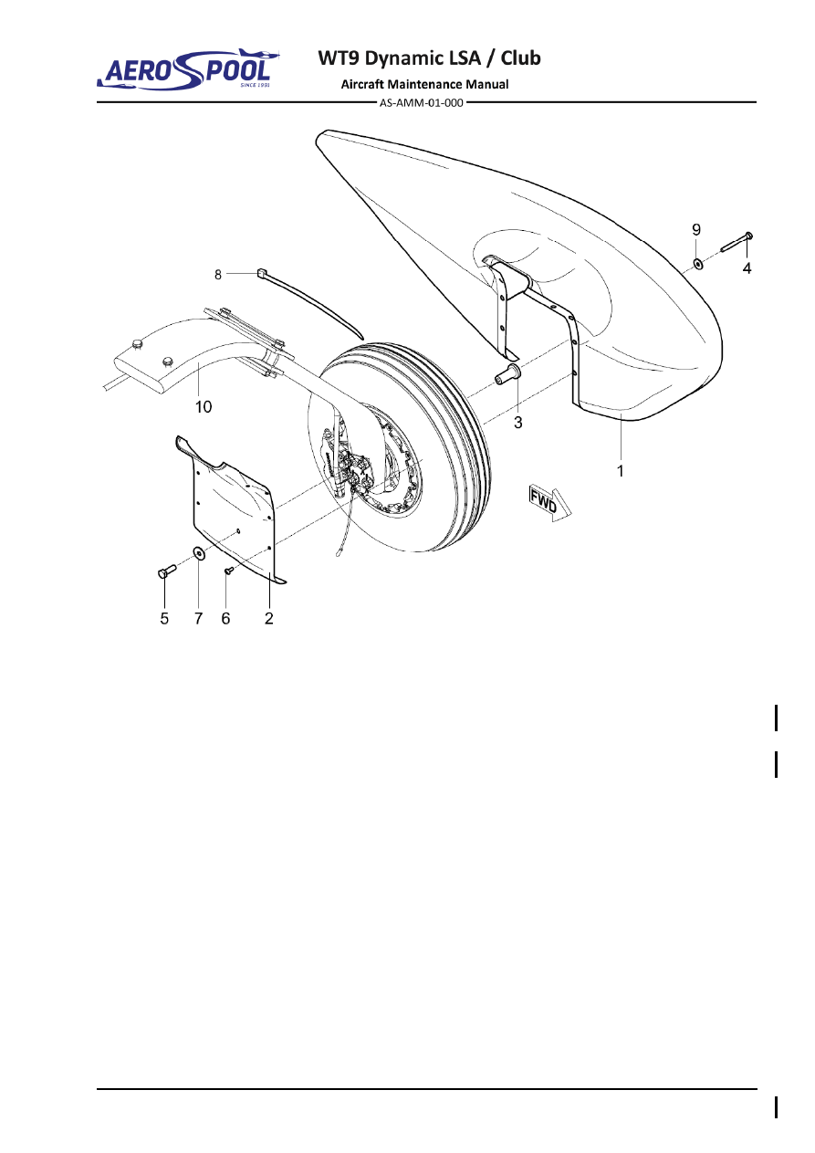
– Main wheel fairing 

– Washer ø8.4 x 24 x 2 

– Inner cover 

– Cable tie 4.8 

– Distance tube 

– Washer ø6.4 x 18 x 1.6 

– Bolt M6 x 60 

For information: 

– Bolt M8 x 25 

10 

– Main landing gear leg 

– Bolt M5 x 12 


Fig. 32-3  Main Wheel Fairing Removal / Installation 


Effectivity:

 ALL 

04. 07. 2019


LANDING GEAR 


B. 

Main wheel 

The procedure for removal of the left main wheel is described. 

Type of maintenance: 

Heavy 

Personnel qualification: 

Independent  certifying  staff  qualified  in  accordance 


with Part-66 or higher. 

Recommended tools, materials, persons and documentation: 

ITEM 

QUANTITY 

Phillips screwdriver 

1 pc 

Pliers 

1 pc 

Wrench 32 

1 pc 

Persons 

Tab. 32-2 Recommended tools, materials, persons and documentation 

(1)  Main wheel removal: 

(a)  Jack the aircraft and secure the tail (Chapter 07-10). 

(b)  Remove the main gear fairing (see 2.A.(1)). 

(c)  Remove the split pin (6, Fig. 32-4), unscrew the nut (4) and remove 

the distance tube (5). 

(d)  Remove  the  safety  stainless  wire  (2)  and  pull  the  main  wheel  (1)  

with the brake disc (3) out. 

(2)  Main wheel installation: 

(a)  Before  assembling  the  main  landing  gear,  ensure  the  wheel  axle 

connection is not damaged. 

(b)  Align  the  brake  disc  (3,  Fig.  32-4)  with the gap  in  the  brake  caliper; 

install the wheel (1) on the wheel axle (7). 

NOTE 

Tabs of the brake disc (3) must fit between the wheel disc tabs. 

(c)  Install  the  distance  tube  (5),  tighten  the  nut  (4)  and  lock  it  with  

the split pin (6). 

(d)  Wind the safety stainless wire (2) around the disc tabs and secure it. 

(e)  Install the main wheel fairing (see 2.A.(2)). 

(f) 

Carry out a test and check: 

  If all bolt connections are tight. 

  Plays. 

  Free rotation of the main wheel. 

  Tire pressure (250 kPa). 

  If grounding wire is touching the ground. 


MAIN GEAR 


LANDING GEAR  


– Main wheel 

– Distance tube 

– Safety stainless wire ø1 mm 

– Split pin ø0.8 mm 

– Brake disc 

– Brake caliper with wheel axle 

– Nut M25 


Fig. 32-4  Main Wheel Removal / Installation


Effectivity:

 ALL 

12. 06. 2020


LANDING GEAR 


C. 

Main landing gear leg 

Type of maintenance: 

Heavy 

Personnel qualification: 

Independent certifying staff qualified in accordance 


with Part-66 or higher. 

Recommended tools, materials, persons and documentation: 

ITEM 

QUANTITY 

Wrench 10 

1 pc 

Wrench 13 

1 pc 

Hex key 6 

1 pc 

Screwdriver  

1 pc 

Socket 13 

1 pc 

Pliers 

1 pc 

Drill bit ø8 mm 

1 pc 

Split pin ø2 x 32 mm 

4 pcs 

Stainless wire ø1 mm 

AR 

Silicone 

AR 

Contact adhesive 

AR 

Sealing adhesive tape 

AR 

Loctite 243 

AR 

Persons 

Tab. 32-3 Recommended tools, materials, persons and documentation 

(1)  Main landing gear leg removal: 

(a)  Jack the aircraft and secure the tail (Chapter 07-10). 

(b)  Remove the main wheel (see 2.B.(1)). 

(c)  Remove the split pins (11, Fig. 32-5) and unscrew the nuts (6). 

(d)  Remove the washer (7), disconnect the wire (22), cable (10), remove 

the inner holder (8), guying plate (9), washers (5), bolts (3; 4). 

(e)  Disconnect the brake caliper with wheel axle (2). 

NOTE 

Disassembly of the brake caliper from the wheel axle is described 
in Chapter 32-40. 

(f) 

Release  the  brake  line  from  the  main  landing  leg  (1)  by  removing  
the adhesive tape (21).  

(g)  Under the wing centre section, remove the cover (8, Chapter 06-00). 

(h)  Remove  the  laminated  seat  (Chapter  25-10)  and  remove  the  side 

cover (6, Chapter 06-00) with a knife. 


MAIN GEAR 


LANDING GEAR  

(i) 

Tear  off  the  upholstery;  remove  the  cover  (5,  Chapter  06-00)  
with a knife. 

(j) 

On  the  lower  attachment  (24,  Fig.  32-5),  unscrew  the  nuts  (19), 
remove the washers (7), bottom support (17), support distance tubes 
(15)  rubber  plate  (16),  rubber  plate  (13),  washer  plate  (12)  
and bolts (18). 

(k)  On  the  upper  attachment  (23),  unscrew  the  nuts  (19),  remove  

the washers (7) and bolts (20). 

(l) 

Pull the main landing leg (1) from the aircraft. 

(2)  Main landing gear leg installation: 

(a)  Before  assembly  of  the  main  landing  gear,  check  the  outer  surface  

of  the  landing  gear  leg  for  any  cracks  and  ensure  the  wheel  axle 
connection is not damaged. 

(b)  Insert the main landing leg (1, Fig. 32-5) into the centre section. 

NOTE 

In  case  of  new  main  landing  gear  leg:  Align  the  flat  end  
of  the  main  landing  gear  leg  (1)  with  the  ends  on  the  upper 
attachment  (23).  Secure  firmly  and  make  new  holes  into  main 
landing  gear  leg  (1)  according  to  the  holes  in  the  upper 
attachment (23) by using 

ø8 mm drill. 

(c)  On  the  upper  attachment  (23),  install  the  bolts  (20),  washers  (7)  

and slightly tighten the nuts (19). 

(d)  On  the  lower  attachment  (24),  install  the  rubber  plate  (13),  washer 

plate (12) and bolts (18). 

(e)  Install support distance tubes (15), rubber plate (16), bottom support 

(17), washers (7) and slightly tighten the nuts (19). 

(f) 

Tighten all nuts (19) connecting the landing leg (1) with the aircraft. 

(g)  Bond  the  covers  (5;  6;  Chapter  06-00)  with  silicone  (remove  old 

silicone); glue the upholstery with contact adhesive. 

(h)  Install the laminated seat (Chapter 25-10). 

(i) 

Under the wing centre section install the cover (8, Chapter 06-00). 

(j) 

Attach the brake line and grounding wire with sealing adhesive tape 
(21, Fig. 32-5) in the middle of the main landing leg. 

(k)  On  the  bottom  of  the  main  landing  leg,  install  the  wheel  axle  

with brake caliper (2), bolts (3; 4), washers (5), guying plate (9), inner 
holder (8), cable (10) with grounding wire (22) and washer (7); tighten 
the nuts (6) and lock them with new split pins (11). 

(l) 

Install the main wheel (see 2.B.(2)). 


Effectivity:

 ALL 

04. 07. 2019


LANDING GEAR 


(m)  Carry out a test and check: 

  That the castle nuts are secured with split pins. 

  If all bolt connections are tight. 

  Plays. 

  Free rotation of the main wheel. 

  Tire pressure (250 kPa). 

  If grounding wire is touching the ground. 

  That no foreign objects remain in the aircraft. 

  There is no air in the brake system. 

(3)  Main landing gear inspection / check: 

In  the  following  table  are  shown  the  permissible  plays  for  main  landing  
gear attachment. These values should be not exceeded in operation. 


SYSTEM 

PROCEDURE TO FIND 
A PLAY 

PROCEDURE 
TO REMEDY A 
PLAY 

MAX. 

PRODUCT. 

PLAY 

MAX. 

OPERATING 

PLAY 

Main 
landing 
gear  

Lift the aircraft. Move the 
main wheel 
forward/backward and 
inboard/outboard to find 
possible plays.  

Check the legs 
attachment, 
wheels 
attachment. 
Replace the 
bearings, if 
necessary.  

1 mm / 

0.039 in 

3 mm / 

0.118 in 

Tab. 32-4 Maximum Permissible Plays 


MAIN GEAR 


LANDING GEAR  


Fig. 32-5  Main Landing Gear Leg Removal / Installation (page 1 of 2) 


Effectivity:

 ALL 

04. 07. 2019


LANDING GEAR 


–  Main landing gear leg 

14 -  Empty 

–  Brake caliper with wheel axle 

15 -  Support distance tube 

–  Bolt M8 x 52 

16 -  Rubber plate 

–  Bolt M8 x 57 

17 -  Bottom support 

–  Cut washer ø8.4 

18 -  Bolt M8 x 58 

–  Castle nut M8 

19 -  Self-locking nut M8 

–  Washer ø8.4 x 16 x 1.6 

20 -  Bolt M8 x 48 

8 - 

Inner holder 

21 -  Sealing adhesive tape 

9 - 

Guying plate 

22 -  Grounding wire 

10 -  Cable 

For information: 

11 -  Split pin 

ø2 x 32 

23 -  Upper attachment 

12 -  Washer plate 

24 -  Lower attachment 

13 -  Rubber plate 


Fig. 32-5  Main Landing Gear Leg Removal / Installation (page 2 of 2) 


NOSE GEAR 


LANDING GEAR  

32-20  NOSE GEAR 

1.  DESCRIPTION 

The  metal  nose  landing  gear  leg  (1,  Fig.  32-6)  with  carbon  fork  (2)  is  attached  
to  the  firewall  in  the  lower  (3)  and  upper  (4)  supports.  The  nose  landing  gear 
incorporates  bungees (5)  (nose  leg  -  lower  support)  and  rubber damper  (nose  leg  - 
upper support). Nose leg is steerable and controlled by foot control pedals by means 
of pull-push rods and is fitted with the centring mechanism (7). 

The  nose  landing  gear  is  equipped  with  aluminium  wheel  disc  with  tubeless  tire  (6) 
(see Chapter 32-40). 

The nose wheel is fitted with the aerodynamic fairing (8). 

Increased attention during periodic inspections,  especially after a hard landing must 
be focused on cracks in the critical areas of nose gear components. 
The critical area on the nose landing gear leg (1, Fig. 32-6) is located around the weld  
of  main  tube  and  reinforcement  tube  (CA1).  The  critical  area  of  upper  support  (2)  
is located around the weld of support’s tube and lid (CA2). 


Effectivity:

 ALL 

04. 07. 2019


LANDING GEAR 


– Landing gear leg 

– Bungee 

– Carbon fork 

– Nose wheel 

– Lower support 

– Centring mechanism 

– Upper support 

– Wheel fairing 

Fig. 32-6  Nose Landing Gear 


NOSE GEAR 


LANDING GEAR  

2.  MAINTENANCE PRACTICES 

A. 

Nose wheel fairing 

Type of maintenance: 

Line 

Personnel qualification: 

Independent certifying staff qualified in accordance 


with Part-66 or higher. 

Recommended tools, materials, persons and documentation: 

ITEM 

QUANTITY 

Screwdriver 

1 pc 

Pliers 

1 pc 

Hex key 6 

1 pc 

Wrench 10 

1 pc 

Wrench 13 

1 pc 

Loctite 243 

AR 

Persons 

Tab. 32-5 Recommended tools, materials, persons and documentation 

(1)  Nose wheel fairing removal: 

(a)  Unscrew the bolts (6, Fig. 32-7) and remove the cover (2). 

(b)  Unscrew the bolts (3; 4; 5) and remove the washers (7; 8; 9). 

(c)  Remove the wheel fairing (1) with the distance roller (10). 

(2)  Nose wheel fairing installation: 

(a)  Thoroughly clean the inside of the fairing before each installation. 

(b)  Adjust  the  wheel  fairing  (1,  Fig.  32-7)  with  the  distance  roller  (10)  

to the appropriate position. 

(c)  Install  the  washers  (7;  8;  9);  apply  Loctite  243  on  the  bolts  threads  

and screw the bolts (3; 4; 5) in. 

(d)  Install the cover (2) using the bolts (6). 


Effectivity:

 ALL 

04. 07. 2019


LANDING GEAR 


– Nose wheel fairing 

–  Bolt M5 x 12 

– Cover 

–  Washer ø8.4 x 24 x 2 

– Bolt M8 x 35 

–  Washer ø6.4 x 18 x 1.6 

– Bolt M6 x 16 

–  Serrated locking washer ø6.4 

– Allen bolt M6 x 10 

10 

–  Distance roller 

Fig. 32-7  Nose Wheel Fairing Removal / Installation 


NOSE GEAR 


LANDING GEAR  

B. 

Nose wheel 

Type of maintenance: 

Heavy 

Personnel qualification: 

Independent certifying staff qualified in accordance 


with Part-66 or higher. 

Recommended tools, materials, persons and documentation: 

ITEM 

QUANTITY 

Wrench 10 

2 pcs 

Wrench 13 

1 pc 

Wrench 24 

2 pcs 

Screwdriver 

1 pc 

Knife 

1 pc 

Socket 10 

1 pc 

Persons 

Tab. 32-6 Recommended tools, materials, persons and documentation 

(1)  Nose wheel removal: 

(a)  Jack the aircraft and secure the tail (Chapter 07-10). 

(b)  Remove the nose wheel fairing (see 2.A.(1)). 

(c)  Unscrew the bolt (8, Fig. 32-8), remove the washer (9) and the wheel 

fairing bracket (7). 

(d)  Unscrew  the  bolt  (5),  remove  the  tab  washer  (6)  and  pull  the  nose 

wheel axle (2) out. 

(e)  Remove  the  nose  wheel  (1)  with  the  short  distance  tube  (4)  and  

the long distance tube (3). 

(2)  Nose wheel installation: 

(a)  Insert  the  nose  wheel (1,  Fig.  32-8)  with  the  short  distance  tube  (4) 

and the long distance tube (3) into the carbon fork (10). 

(b)  Slide  the  nose  wheel  axle  (2)  from  the  left  side  in;  install  the  tab  

washer (6), tighten and secure the bolt (5) by bending of washer. 

(c)  Install the wheel fairing bracket (7), the washer (9), apply Loctite 243 

on the bolt (8) thread and tighten the bolt (8). 

(d)  Check  free  rotation  of  the  wheel  (1)  and  if  the  braking  plate  (11)  is 

effectively braking the wheel. 

(e)  Install the nose wheel fairing (see 2.A.(2)). 

(f) 

Carry out a test and check: 

  If all bolt connections are tight. 

  Plays. 

  Free movement, rotation and damping of the nose landing gear. 

  If the brake plate is braking the wheel. 

  Tire pressure (200 kPa). 

  That no foreign objects remain in the aircraft. 


Effectivity:

 ALL 

04. 07. 2019


LANDING GEAR 


Fig. 32-8  Nose Wheel Removal / Installation (page 1 of 2) 


NOSE GEAR 


LANDING GEAR  


– Nose wheel 

–  Wheel fairing bracket 

– Nose wheel axle 

–  Bolt M8 x 12 

– Long distance tube 

–  Washer ø8.4 x 16 x 1.6 

– Short distance tube 

10 

–  Fork 

– Bolt 

11 

–  Braking plate 

– Tab washer 


Fig. 32-8  Nose Wheel Removal / Installation (page 2 of 2) 


Effectivity:

 ALL 

04. 07. 2019


LANDING GEAR 


C. 

Nose landing gear leg 

Type of maintenance: 

Heavy 

Personnel qualification: 

Independent certifying staff qualified in accordance 


with Part-66 or higher. 

Recommended tools, materials, persons and documentation: 

ITEM 

QUANTITY 

Wrench 10 

2 pcs 

Wrench 13 

1 pc 

Wrench 24 

2 pcs 

Screwdriver 10 

1 pc 

Hex key 2 

1 pc 

Socket 10  

1 pc 

Hand riveting tool 

1 pc 

Heat gun 

1 pc 

Knife 

1 pc 

Drill  

1 pc 

Drill bit 

ø4 mm 

1 pc 

Rubber rope 

AR 

Split pin 

ø2 x 32 mm 

2 pcs 

Lock wire 

ø1.2 mm 

AR 

Vaseline 

AR 

Loctite 243 

AR 

Persons 

Tab. 32-7 Recommended tools, materials, persons and documentation 

(1)  Nose landing gear leg removal: 

(a)  Jack the aircraft and secure the tail (Chapter 07-10). 

(b)  Remove the engine cowlings (Chapter 71-10). 

(c)  Remove the nose wheel (see 2.B.(1)). 

(d)  Disconnect  the  push  rods  from  the  landing  strut  levers  

(Chapter 32-50). 

(e)  Cut the rubber ropes (12, Fig. 32-9). 

(f) 

Unscrew the nuts (30) and the bolts (32) and remove the springs (29). 

(g)  Unscrew the bolts (25), remove the washers (15) and the tube (26). 

(h)  Remove the split pins (17) and the tube (10). 

(i) 

Remove the circlips (24), guiding wheels (6), guiding wheel axle (5). 

(j) 

Remove the damping plate (11). 


Content      ..     21      22      23      24     ..