WT9 Dynamic LSA. AIRCRAFT MAINTENANCE MANUAL (AS-AMM-01-000, 22. 05. 2017) - page 21


  Index      Manuals     WT9 Dynamic LSA. AIRCRAFT MAINTENANCE MANUAL (AS-AMM-01-000, 22. 05. 2017)


Search            copyright infringement  


Content      ..     19      20      21      22     ..


WT9 Dynamic LSA. AIRCRAFT MAINTENANCE MANUAL (AS-AMM-01-000, 22. 05. 2017) - page 21


DISTRIBUTION 


FUEL


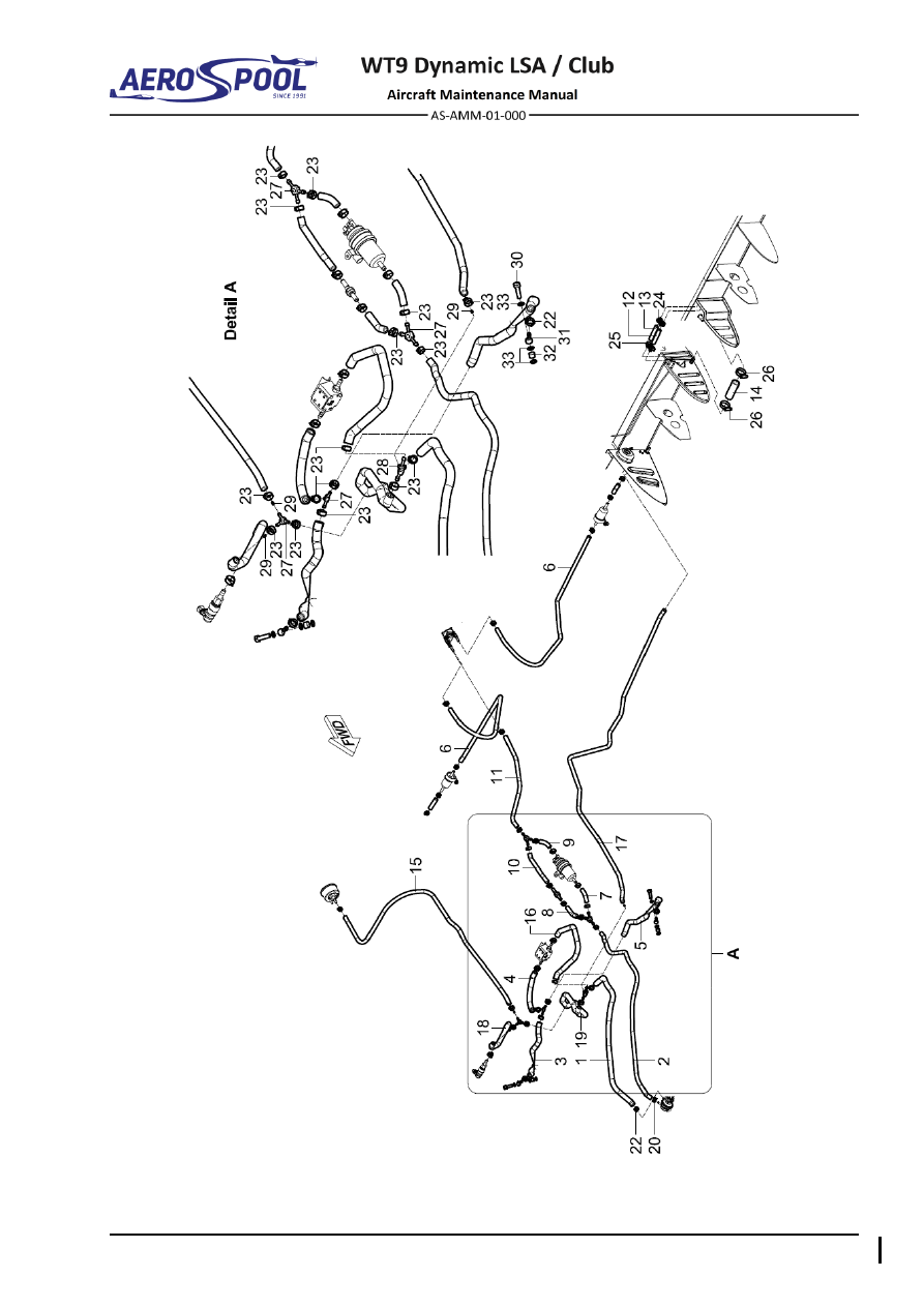
Fig. 28-7  Fuel Line Removal / Installation (page 1 of 2) 


Effectivity:

 ALL 

04. 07. 2019


FUEL


–  Fuel hose 

13 

–  Fuel hose 

25 

–  Hose clamp ø8 - 12 

–  Fuel hose 

14 

–  Fuel hose 

26 

–  Hose clamp ø20 - 32 

–  Fuel hose 

15 

–  Fuel hose 

27 

–  3-way distributor 

–  Fuel hose 

16 

–  Fuel hose 

28 

–  4-way distributor 

–  Fuel hose 

17 

–  Fuel hose 

29 

–  Restrictor jet 

–  Fuel hose 

18 

–  Fuel hose 

30 

–  Banjo bolt 

–  Fuel hose 

19 

–  Fuel hose 

31 

–  Banjo eye 

–  Fuel hose 

20 

–  Hose clamp 14.5 

32 

–  Distance tube 

–  Fuel hose 

21 

–  Hose clamp 13.3 

33 

–  Cooper gasket ring ø8 x 12 x 1 

10 

–  Fuel hose 

22 

–  Hose clamp 13.8 

34 

–  Socket 

11 

–  Fuel hose 

23 

–  Hose clamp 14 

35 

–  Fuel strainer 

12 

–  Fuel hose 

24 

–  Hose clamp 15.5 


Fig. 28-7  Fuel Line Removal / Installation (page 2 of 2) 

G. 

Ventilation line 

Type of maintenance: 

Line 

Personnel qualification: 

Independent certifying staff qualified in accordance 
with Part-66 or higher.  

Recommended tools, materials, persons and documentation: 

ITEM 

QUANTITY 

Screwdriver 5 

1 pc 

Phillips screwdriver 

1 pc 

Pliers 

1 pc 

Oetiker Pliers 

1 pc 

Cable tie 2.6 

AR 

Hose clamps (as appropriate) 

AR 

Persons 

Tab. 28-8 Recommended tools, materials, persons and documentation 

WARNING 

GROUND  THE  EXHAUST  PIPE  OUTLET  AND  FUEL  SERVICE 
EQUIPMENT PRIOR TO AIRCRAFT REFUELLING/DEFUELING! 

ENGINE IGNITION MUST BE SWITCHED OFF! 

DRAINING  ALL  FUEL  FROM  THE  FUEL  SYSTEM  IS  NOT 
POSSIBLE,  BE  CAREFUL  DURING  DISASSEMBLING  THE  FUEL 
SYSTEM!


DISTRIBUTION 


FUEL


(1)  Ventilation line removal: 

  Make sure that the 

IGNITION

 switches are set to 

OFF

  Remove engine cowlings (Chapter 71-10). 

  Disconnect negative terminal of battery (Chapter 24-30). 

  Electrically  ground  the  aircraft  (use  the  exhaust  pipe  outlet)  

to the grounding point. 

  In  cockpit  on  left  and  right  side  under  canopy  remove  hose  clamps  

(2, Fig. 28-8), disconnect ventilation hoses (1). 


Remove  cable  ties  (3)  on  length  of  ventilation  hoses.  Pull  out 
ventilation hoses. 

(2)  Ventilation line installation: 

  In cockpit on left and right side under canopy, slide ventilation hoses 

(1, Fig. 28-8) on hose sockets and secure them with hose clamps (2). 

  Route the ventilation hoses (1) and secure them with cable ties (3). 

  Seal grommet in floor with silicone sealant. 

  Cut  slant  end  of  ventilation  hoses  6  cm  under  fuselage.  Taper  

to the rear. 

  Remove the ground cable from the aircraft. 


–  Ventilation hose 

–  Cable tie 2.6 

–  Hose clamp 11.3 


Fig. 28-8  Ventilation Line Removal / Installation


INDICATING 


FUEL


28-40  INDICATING 

1.  DESCRIPTION 

The  fuel  level  sensor  is  installed  in  the  both  left  and  right  fuel  tank  on  the  root  rib  
of fuselage fuel tank. Signal from the fuel level sensor is carried via low value warning 
unit  and  from  there  to  the  engine  monitoring  system  unit  Dynon  SV-EMS  220  and  
from  there  to  the  Dynon  SkyView  SV-D1000.  Low  fuel  quantity  (less  than  16  litres)  
is  signalized  with  the 

LH  FUEL  RES  /  RH  FUEL  RES

  red  warning  lamps  

(Chapter 39-10). 

Fuel  pressure  sensor  and  standby  fuel  pressure  indicator  are  installed  in  the  fuel 
system and  connected  through  the  3-way  distributor  with  restrictor  jets  in  its  outlets  
to the 4-way distributor. Both check the actual pressure in the fuel supply line. Signal 
from the sensor is carried to the engine monitoring system unit Dynon SV-EMS 220 
and from there to the Dynon SkyView SV-D1000. 

Exceeding  of  fuel  pressure  limit  value  is  signalized  by  red  warning  lamp 

EMS


on the instrument panel (Chapter 39-10). 

The fuel flow transducer is located on the engine mount top. The electrically operated 
fuel flow transducer transmits fuel flow rate data to the engine monitoring system unit 
Dynon EMS 220 and from there to the Dynon SkyView SV-D1000. 

2.  MAINTENANCE PRACTICES 

A. 

SV-D1000 display 

For removal / installation procedures refer to Chapter 39-10. 

B. 

SV-EMS-220 module 

For removal / installation procedures refer to Chapter 77-40. 

C. 

Low value warning unit 

For removal / installation procedures refer to Chapter 31-50. 

D. 

Standby fuel pressure indicator 

For removal / installation procedures refer to Chapter 39-10. 


Effectivity:

 ALL 

12. 06. 2020


FUEL


E. 

Fuel level sensor 

Type of maintenance: 

Line 

Personnel qualification: 

Independent certifying staff qualified in accordance 
with Part-66 or higher.  

Recommended tools, materials, persons and documentation: 

ITEM 

QUANTITY 

Wrench 8 

1 pc 

Screwdriver  

1 pc 

Pliers 

1 pc 

Oetiker Pliers 

1 pc 

Loctite 577 

AR 

Persons 

Tab. 28-9 Recommended tools, materials, persons and documentation 

WARNING 

GROUND  THE  EXHAUST  PIPE  OUTLET  AND  FUEL  SERVICE 
EQUIPMENT PRIOR TO AIRCRAFT REFUELLING/DEFUELING! 

ENGINE  IGNITION  MUST  BE  SWITCHED  OFF.  DISCONNECT 
NEGATIVE TERMINAL OF AIRCRAFT BATTERY. 

DRAINING  ALL  FUEL  FROM  THE  FUEL  SYSTEM  IS  NOT 
POSSIBLE,  BE  CAREFUL  DURING  DISASSEMBLING  THE  FUEL 
SYSTEM. 

NOTE 

Described is left side. The right side is mirrored. 

(1)  Fuel level sensor removal: 

  Make sure that the 

IGNITION

 switches are set to 

OFF

  Remove engine cowlings (Chapter 71-10). 

  Disconnect negative terminal of battery (Chapter 24-30). 

  Electrically  ground  the  aircraft  (use  the  exhaust  pipe  outlet)  

to the grounding point. 

  Drain fuel tanks (Chapter 12-10). 


Inside of the cockpit to the left and right of the wing pin remove round 
cover (3, Fig. 06-4, Chapter 06-00). 

  Disconnect connectors (5, Fig. 28-9). 

  Unscrew the bolts (3) with washers (4). 


Pull out fuel float LH/RH (1) with seal (2). 


INDICATING 


FUEL


(2)  Fuel level sensor installation: 

  Make sure that the 

IGNITION

 switches are set to 

OFF

  In cockpit on side, put fuel float (1, Fig. 28-9) with seal (2). 

  Put washers (4), tighten the bolts (3) secured with Loctite 577. 

  Connect connectors (5). 

  Check if sensor is firmly secured and sealed. 


Install  round  cover  (3,  Fig.  06-4)  from  inner  side  of  the  cockpit  
to the left and right side near main wing pin. 

  Connect negative terminal of the battery (Chapter 24-30). 

  Install engine cowlings (Chapter 71-10). 


Remove the ground cable from the aircraft. 


Replenish the fuel system (Chapter 12-10). 

  Carry  out  engine  ground  test;  check  fuel  system  for  leaks  and  fuel 

system indication. 


(3)  Adjustment  /  Test 

–  calibration  and  check  of  a  correct  function  

of the measurement system and indication of fuel quantity 

Carry  out  this  procedure  on  the  aircraft  with  completely  finished  fuel 
installation. 

Perform the procedure in a suitable and exactly defined space. In this space 
and 

in its vicinity don´t carry out, in the course of the calibration, any other 

work than the work necessary for performing the calibration. 

As working and procedure medium for this calibration, use gasoline Natural 
95 or aviation gasoline Avgas 100LL. 

During  this  procedure,  perform  the  tank  filling  with  fuel  by  means  
of  the  calibration  device  or  the  calibration  vessel  so  that  it  is  possible  
to  determine  a  precise  quantity  of  added  fuel.  For  the  same  reason,  use  
the  calibration  device  or  the  calibration  vessel  also  when  draining  fuel  
from  the  tank.  When  handling  fuel,  use  the  clothing  that  doesn´t  contain 
artificial clothes. 

WARNING 

UNAUTHORIZED ENTRY TO THE SYSTEM SETTINGS AND NON-
OBSERVANCE  OF  THE  DEFINED  CALIBRATION  PROCEDURES 
MAY  CAUSE  AN  INCORRECT  FUNCTIONALITY  OR  A  TOTAL 
FAILURE OF THE WHOLE SKYVIEW SYSTEM! 

NOTE 

Refer  to  “Dynon  Avionics  SkyView  System  Installation,  Document 
101320-022, 

Revision Q” or later for additional information.


Effectivity:

 ALL 

12. 06. 2020


FUEL


  Level the aircraft (Chapter 08-10). 

  Electrically  ground  the  aircraft  (use  the  exhaust  pipe  of  the  aircraft)  

to the grounding point. 

  Check  whether  appropriate  wing  tank  is  empty;  otherwise,  drain  

the fuel (Chapter 12-10). 

  Connect the aircraft to the external power source. 

  Check  whether  the  appropriate  drain  valve  is  closed  and  remove  

the tank filler cap. 


Enter the SETUP MENU of the appropriate SV-D1000 Display. 

  By turning the rotary switch, select HARDWARE CALIBRATION. 

  Move the rotary switch to the right and select EMS CALIBRATION. 


By turning the rotary switch, select the calibrated tank 

– FUEL TANK 

1 or 2 (LEFT or RIGHT) and then move the rotary switch to the right. 


If  you  want  to  edit  the  calibration,  select  EDIT;  if  you  want  to  do  
a recalibration, select RECAL. 

EDIT 

editing of the calibrated values in the table 

– for fine tuning. 

  In  "POINT  1"  for  empty  tank  "VALUE  (LTR)  =  0.0"  set  the  value  

of  "VOLTS"  according  to  the  actual  value  VOLTAGE  SENSOR  
(top  right  corner  of  the  screen).  Save  the  set  value using the  SAVE 
DONE buttons. 


Add to the tank exactly 5 liters of the fuel. Wave with the fuselage and 
wait for spill and stabilization of fuel level in the tank

– the aircraft must 

be at rest. 

  Reselect by the cursor value in "POINT 2" and press ADJUST. 

  In "POINT 2" for tank "VALUE (LTR) = 5.0" set the value of "VOLTS" 

according  to  the  actual  value  VOLTAGE  SENSOR  (top  right  corner  
of the screen). Save the set value using the SAVE DONE buttons. 

  Repeat  procedure  in  accordance  with  points  (l),  (m)  and  (n)  

up to 45 liters. 

  To calibrate opposite fuel tank, repeat steps (i) to (o). 

  Finish  and  save  the  calibration  by  the  DONE  button.  Exit  menu  

by the EXIT button. 


Disconnect  external  power  source  and  grounding  from  the  exhaust 
pipe. 


INDICATING 


FUEL


–  Fuel float LH/RH 

–  Electrical connector 

–  Rubber seal 

For information: 

–  Bolt M5 x 16 

–  Wing rib 

–  Washer ø5.3 x 10 x 1 


Fig. 28-9  Fuel Level Sensor Removal / Installation 


Effectivity:

 ALL 

12. 06. 2020


FUEL


F. 

Fuel pressure sensors 

Type of maintenance: 

Line 

Personnel qualification: 

Independent certifying staff qualified in accordance 
with Part-66 or higher.  

Recommended tools, materials, persons and documentation: 

ITEM 

QUANTITY 

Wrench 8 

2 pcs 

Wrench 10 

2 pcs 

Wrench 14 

1 pc 

Pliers 

1 pc 

Oetiker Pliers 

1 pc 

Philips screwdriver 2 

1 pc 

Loctite 542 

AR 

Persons 

Tab. 28-10 Recommended tools, materials, persons and documentation 

WARNING 

GROUND  THE  EXHAUST  PIPE  OUTLET  AND  FUEL  SERVICE 
EQUIPMENT PRIOR TO AIRCRAFT REFUELLING/DEFUELING! 

ENGINE  IGNITION  MUST  BE  SWITCHED  OFF.  DISCONNECT 
NEGATIVE TERMINAL OF AIRCRAFT BATTERY. 

(1)  Fuel pressure sensor ROAD removal: 

  Make sure that the 

IGNITION

 switches are set to 

OFF

  Remove the engine cowlings (Chapter 71-10). 

  Disconnect negative terminal of battery (Chapter 24-30). 

  Electrically  ground  the  aircraft  (use  the  exhaust  pipe  outlet)  

to the grounding point. 

  Remove the instrument panel cover (Chapter 39-10). 


Disconnect connector (11, Fig. 28-10) from pressure sensor (1). 

  Remove hose clamp (9) and disconnect the


hose socket (7) from hose 

(10). 

  Unscrew the nut (6), remove washers (4; 5), bracket (2), bolt (3) and 

sensor (1). 


Disassemble  the  fuel  pressure  sensor  (1)  by  unscrewing  the  fuel 
socket (7) and remove sealing ring (8). 


Put the caps on the hose and sensor port. 


INDICATING 


FUEL


(2)  Fuel pressure sensor ROAD installation:  

  Make sure that the battery is disconnected. 

  Remove the caps from the sensor port and hose. 

  If pyrojacket (fire sleeve) is not already in place, fit it on.


  Assemble  pressure  sensor  (1,  Fig.  28-10),  by  screwing  hose  socket 

(7) with sealing ring (8) secured with Loctite 542. 

  Connect fuel hose (10) at pressure sensor (1) and secure with  hose 

clamp (9). 


Apply the Pyrosil end sealing tape. 

  Slide bracket (2) on pressure sensor (1). 

  Put the bolt (3), washers (4; 5), bracket (2) and tighten the nut (6). 


Check that connector’s wires (11) are connected to 12V output of EMS 
module  and  connect  it  to  pressure  sensor  (1)  (see  Aircraft  Wiring 
Manual (Doc. No. AS-AWM-01-000). 

NOTE 

Connector  wires  must  be  connected  to  12V  output  of  EMS 
module,  otherwise  the  fuel  pressure  sensor  will  not  operate 
correctly. 


Remove the ground cable from the aircraft. 

  Connect negative terminal of the battery (Chapter 24-30). 


Install the engine cowlings (Chapter 71-10). 

  Install the instrument panel cover (Chapter 39-10).  

  Install  the  file  FPS_ROAD.duc  to  both  LH  and  RH  displays  Dynon 

SkyView SV-D1000 (see Chapter 39-10). 

  Carry out an operational test. 


Effectivity:

 ALL 

12. 06. 2020


FUEL


–  Fuel pressure sensor 

–  Sealing ring ø10 x 15 x 1.5 

–  Bracket 

–  Hose clamp ø14.5 

–  Bolt M5 x 20 

10 

–  Hose 

–  Washer ø5.3 x 15 x 1.2 

11 

–  Electrical connector 

–  Washer ø5.3 x 10 x 1 

For information: 

–  Nut M6 

12 

–  Firewall 

–  Hose socket 


Fig. 28-10  Fuel Pressure Sensor ROAD Removal / Installation


INDICATING 


FUEL


(3)  Fuel pressure sensor KAVLICO removal:  

  Make sure that the 

IGNITION

 switches are set to 

OFF

  Remove the engine cowlings (Chapter 71-10). 

  Disconnect negative terminal of battery (Chapter 24-30). 

  Electrically  ground  the  aircraft  (use  the  exhaust  pipe  outlet)  

to the grounding point. 

  Remove the instrument panel cover (Chapter 39-10). 


Disconnect connector (11, Fig. 28-11) from pressure sensor (1). 

  Remove  hose  clamp  (9)  and  disconnect  the


hose  (10)  from  hose 

socket (7). 

  Unscrew the nut (6), remove washers (4; 5; 8), bracket (2), bolt (3) and 

sensor (1). 


Disassemble  the  fuel  pressure  sensor  (1)  by  unscrewing  the  fuel 
socket (7). 


Put the caps on the hose and sensor port. 

(4)  Fuel pressure sensor KAVLICO installation: 

  Make sure that the battery is disconnected. 

  Remove the caps from the sensor port and hose. 

If pyrojacket (fire sleeve) is not already in place, fit it on. 

  Assemble pressure sensor (1, Fig. 28-11) by screwing hose socket (7) 

secured with Loctite 542. 

  Connect  fuel hose (10) at  socket  of  pressure sensor (1) and secure 

with hose clamp (9). 

  Apply the Pyrosil (sealing tape) on hose end (10). 


Slide bracket (2) on pressure sensor (1). 

  Put  the  bolt  (3),  washers  (4;  5;  8),  bracket  (2)  and  tighten  them  

by the nut (6). 


Check that connector’s wires (11) are connected to 5V output of EMS 
module  and  connect  it  to  pressure  sensor  (1)  (see  Aircraft  Wiring 
Manual (Doc. No. AS-AWM-01-000). 

CAUTION 

CONECTOR  WIRES  MUST  BE  CONNECTED  TO  5V  EMS 
MODULE  OUTPUT,  OTHERWISE  THE  FUEL  PRESSURE 
SENSOR WILL BE DAMAGED. 


Remove the ground cable from the aircraft. 


Connect negative terminal of the battery (Chapter 24-30). 

  Install the engine cowlings (Chapter 71-10). 


Install the instrument panel cover (Chapter 39-10). 

  Install the file FPS_KAVLICO.duc to both LH and RH displays Dynon 

SkyView SV-D1000 (see Chapter 39-10). 

  Carry out an operational test. 


Effectivity:

 ALL 

12. 06. 2020


FUEL


–  Fuel pressure sensor 

–  Washer ø 6.4 x 20 x 6 

–  Bracket 

–  Hose clamp ø14.5 

–  Bolt M6 x 28 

10 

–  Hose 

–  Washer ø6.4 x 18 x 1.6 

11 

–  Electrical connector 

–  Washer ø6.4 x 12 x 1.6 

For information: 

–  Nut M6 

12 

–  Firewall 

–  Hose socket 


Fig. 28-11  Fuel Pressure Sensor KAVLICO Removal / Installation 


INDICATING 


FUEL


G. 

Fuel flow transducer 

Type of maintenance: 

Line 

Personnel qualification: 

Independent certifying staff qualified in accordance 
with Part-66 or higher.  

Recommended tools, materials, persons and documentation: 

ITEM 

QUANTITY 

Wrench 14 

1 pc 

Pliers 

1 pc 

Oetiker Pliers 

1 pc 

Cable tie 4.8 

5 pcs 

Cable tie 2.6 

1 pc 

Loctite 542 

AR 

Persons 

Tab. 28-11 Recommended tools, materials, persons and documentation 

WARNING 

GROUND  THE  EXHAUST  PIPE  OUTLET  AND  FUEL  SERVICE 
EQUIPMENT PRIOR TO AIRCRAFT REFUELLING/DEFUELING! 

ENGINE  IGNITION  MUST  BE  SWITCHED  OFF.  DISCONNECT 
NEGATIVE TERMINAL OF AIRCRAFT BATTERY. 

ENGINE IGNITION MUST BE SWITCHED OFF!


Effectivity:

 ALL 

12. 06. 2020


FUEL


(1)  Fuel flow transducer removal: 

  Make sure that the 

IGNITION

 switches are set to 

OFF

  Remove the engine cowlings (Chapter 71-10). 

  Disconnect negative terminal of battery (Chapter 24-30). 

  Electrically  ground  the  aircraft  (use  the  exhaust  pipe  outlet)  

to the grounding point. 

  Remove  cable  ties  (9;  10,  Fig.  28-12)  and  disconnect  electrical 

connector (8). 


Remove the end sealing tapes, hose clamps (5) and disconnect fuel 
flow transducer (1) from hoses (6; 7). 

  Disassemble the fuel flow transducer, by unscrewing the fuel sockets 

(4). 

  Put the caps on the fuel hose and transducer ports. 

(2)  Fuel flow transducer installation: 

  Make sure that the battery is disconnected. 

  Remove the caps from the transducer ports and hose. 

  Assemble  fuel  flow  transducer,  by  screwing  the  hose  sockets  

(4, Fig. 28-12) secured with Loctite 542. 

  If pyrojacket (fire sleeve) is not already in place, fit it on. 

WARNING 

BEWARE TO ENSURE CORRECT DIRECTION OF FLOW! 

  Connect the fuel hoses (6; 7) at fuel transducer (1) and secure them 

with hose clamps (5). 


Apply the Pyrosil sealing tape. 

  Attach  fuel  flow  transducer  (1)  to  engine  mount  using  plate  (2),  

two pieces distant hoses (3) and cable ties (9). 

  Connect connector (8) and secure with cable tie (10). 


Connect negative terminal of the battery (Chapter 24-30). 


Install the engine cowlings (Chapter 71-10). 

  Remove the ground cable from the aircraft. 


Carry  out  an  operational  test  and  modify  the  fuel  flow  K-factor  
as necessary.


INDICATING 


FUEL


–  Fuel flow transducer 

–  Electrical connector 

–  Rubber plate 

–  Cable tie 4.8 

–  Rubber distant hose 

10 

–  Cable tie 2.6 

–  Hose socket 

11 

–  Pyro jacket covering 

–  Hose clamp 14.5 

For information: 

–  Fuel hose 

12 

–  Engine mount 

–  Fuel hose 


Fig. 28-12  Fuel Flow Transducer Removal / Installation 


Content      ..     19      20      21      22     ..