WT9 Dynamic LSA. AIRCRAFT MAINTENANCE MANUAL (AS-AMM-01-000, 22. 05. 2017) - page 19
 

  Index      Manuals     WT9 Dynamic LSA. AIRCRAFT MAINTENANCE MANUAL (AS-AMM-01-000, 22. 05. 2017)


Search            copyright infringement  


Content      ..     17      18      19      20     ..


WT9 Dynamic LSA. AIRCRAFT MAINTENANCE MANUAL (AS-AMM-01-000, 22. 05. 2017) - page 19


Effectivity:

 ALL 

04. 07. 2019


FLIGHT CONTROLS 


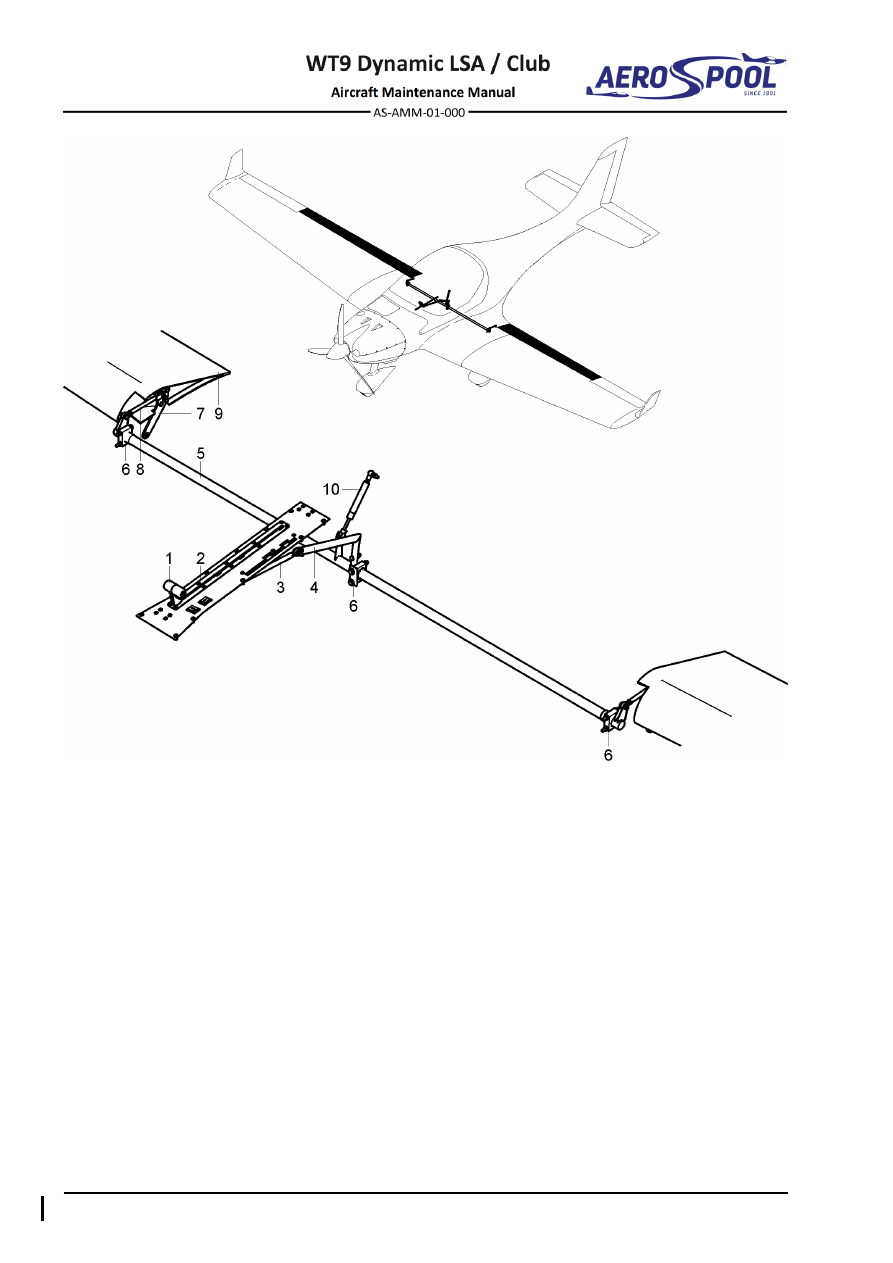
–  Lever 

6 - 

Bearing 

–  Pedestal panel 

7 - 

Wing flap lever 

–  Push-pull rod 1 

8 - 

Push-pull rod 

–  Bellcrank 

9 - 

Wing flap 

–  Torsion tube 

10 -  Gas strut 

Fig.  27-16  Wing Flap Control System 


FLAPS 


FLIGHT CONTROLS 

2.  MAINTENANCE PRACTICES 

Type of maintenance: 

Heavy 

Personnel qualification: 

Independent certifying staff qualified in accordance 
with Part-66 or higher. 

Recommended tools, materials, persons and documentation: 

ITEM 

QUANTITY 

Wrench 10 

2 pcs 

Wrench 8 

1 pc 

Screwdriver 

1 pc 

Puller on small pins M4 

1 pc 

Pliers 

1 pc 

Serrated locking washer 

ø6.4 

2 pcs 

Cotter pin 

ø1.6 x 25 

2 pcs 

Knife 

1 pc 

Vaseline 

AR 

Silicone 

AR 

Protractor with deflecting pointer 

1 pc 

Adhesive tape 

AR 

Ruler 50 cm 

1 pc 

Persons 

Tab. 27-6 Recommended tools, materials, persons and documentation 

A. 

Flap control system 

  Flap control system removal: 

(a)  Remove wings (Chapter 57-10) 

(b)  Disconnect push rod (3, Fig. 27-18) from torsion tube (1), by 

removing nut (12), washer (13) and bolt (7). 

(c)  Remove second push rod (3). 

(d)  Remove pedestal panel (Chapter 27-50, 2.B.(1)). 

(e)  Disconnect bellcrank (2) from torsion tube (1), by removing nut (11), 

washer (13), bolt (8) and remove ground wire (20).  

(f) 

In baggage compartments, remove covers of torsion stick (with knife, 
Velcro attachment) and gas strut cover. 

(g)  Remove gas strut (18). 

(h)  Remove cover on wing root central section with knife. 

(i) 

Disassemble all sliding bearings (6), by removing nuts (11), washers 
(13; 14; 15) and bolts (5; 9). 

(j) 

On right side of centre section, carefully pull out torsion tube (1) 
through access hole. 


Effectivity:

 ALL 

04. 07. 2019


FLIGHT CONTROLS 
 

  Flap control system installation: 

(a)  Before installation check main parts for cracks and condition of rivets 

on push rod.  

(b)  Carefully rotate and slide torsion tube (1, Fig. 27-18) from right side 

of centre section wing root through all holes to other side (wings have 
to be removed). 

(c)  Put all sliding bearings (6) on torsion tube (1) and attach them (1; 6) 

on middle insert and sides carbon holders, by using bolts (5; 9), 
washers (13; 14; 15) and nuts (11). 

NOTE 

Tighten nuts (11) so that the torsion tube (1) rotates easily. 

(d)  Stick cover on centre section roots with silicone (remove old 

silicone). 

(e)  Connect bellcrank (2) to torsion tube (1), by using bolt (8), washer 

(13) nut (11) and ground wire (20).  

(f) 

Install push rod and pedestal panel (Chapter 27-50, 2.B.(2)). 

(g)  In right baggage compartment attach gas strut (18) to torsion tube 

lever and ball joint.  

CAUTION 

GAS  STRUT  HAS  TO  BE  ORIENTED  WITH  VALVE  SIDE  UP 
AND PISTON ROD DOWN.


(h)  Install gas strut cover. 

(i) 

Attach covers of torsion tube. 

(j) 

Install wings (Chapter 57-10). 

(k)  Connect push rod (3) to torsion tube (1), by using bolt (7), washer 

(13) and nut (12). 

(l) 

Connect push rod (3) to wing flap hinge, by using pin (4) and cotter 
pin (17). If using new push rod(s) (3): 

  Set wing flap lever to position 0 (flaps retracted). 

  Flap trailing edges must be aligned with centre section trailing 

edge (a preload is created in the wing flap control system). 


If previous point isn´t not fulfilled, disconnect pin (4), release lock 
nut (10) and screw push rod (3) to adjust to correct length. 
Replace washer (16) and tighten lock nut (10); check rod end in 
safety. 

  Secure pin (4) with cotter pin (17). 

(m)  Connect second push rod (3). 


FLAPS 


FLIGHT CONTROLS 

(n)  Carry out test and check: 

  That the pins are secured with cotter pins. 

  If all bolt connections are tight. 

  Free plays. 

  Free movement of flap control system. 

  If deflections of wing flaps are symmetrical. 

  Deflections (Tab. 27-8). 

  Push rod swivel motion in both wing flap positions for binding 

(retracted and fully extended) (Fig. 27-17); if binding occurs, 
realign rod end bearing. 

  That no foreign objects remain in the aircraft. 


Fig.  27-17  Swivel Motion of Push Rod 

  Adjustment / test - flaps deflections: 

Both wing flaps have to be adjusted simultaneously. Described is adjusting 
of the right side. The process for the left side is mirrored. 
 

CONTROL SURFACE DEFLECTIONS 

Control surface 

Up 

Deflection 

Distance measurement point 

from the point of rotation 

Wing flaps 

FLAPS 1 

15 ±2° 

76 ±6 mm 

295 mm 

(Root rib of the outer wing) 

FLAPS 2 

24 ±2° 

120 ±6 mm 

FLAPS 3 

35 ±2° 

181 ±6 mm 

Maximum deflection difference between both flaps: ±2°/±6 mm 

Tab.  27-8  Wing Flap Deflections 


Effectivity:

 ALL 

22. 05. 2017


FLIGHT CONTROLS 
 

(a)  Set protractor on trailing edge of wing flap root. 

(b)  Set wing flaps to fully retracted position.  

(c) 

Set the protractor to 0°- starting value for measurement. 

(d) 

Check deflections at first position 15°, second position 24° and third 
position 35°, see Tab. 27-8. 

(e)  Check if deflections are symmetrical on both wing flaps. 

(f) 

If deflections are not within range listed in Tab. 27-8, remove cotter 
pin (17, Fig. 27-18) and pin (4), release lock nut (10), use new 
washer (16) and screw push rod (3) to set correct length. 

(g)  Check if push rod fork (3) is parallel with swivel bearing (19). 

(h)  Tighten lock nut (10). 

(i) 

Connect push rod (3) to wing flap with pin (4) and secure with cotter 
pin (17). 

(j) 

Carry out test and check: 

  That the pins are secured with cotter pins. 

  Free movement of flap control system. 

  Deflections. 

  Push rod swivel motion in both wing flap positions for binding 

(retracted and fully extended) (Fig. 27-17); if binding occurs, 
realign rod end bearing. 

  That no foreign objects remained in the aircraft. 


FLAPS 


FLIGHT CONTROLS 


–  Torsion tube 

11 -  Self-locking nut M6 

–  Bellcrank 

12 -  Nut M6 

–  Push-pull rod 

13 -  Washer 

ø6.4 x 12 x 1.6 

–  Pin  

14 -  Washer 

ø6.4 x 18 x 1.6 

–  Bolt M6 x 52 

15 

–  Washer ø6.4 x 12 x 0.5 

–  Sliding bearing 

16 

–  Serrated locking washer ø6.4 

–  Bolt M6 x 19 

17 

–  Cotter pin ø1.6 x 25 

–  Bolt M6 x 28 

18 

–  Booster 

–  Bolt M6 x 60 

19 

–  Swivel bearing 

10 -  Nut M6 

20 

–  Ground wire 

Fig.  27-18  Flap Control System Removal / Installation 


Effectivity:

 ALL 

04. 07. 2019


FLIGHT CONTROLS 
 

B. 

Pedestal panel 

Type of maintenance: 

Line 

Personnel qualification: 

Independent certifying staff qualified in accordance 
with Part-66 or higher. 

Recommended tools, materials, persons and documentation: 

ITEM 

QUANTITY 

Wrench 10 

2 pcs 

Wrench 8 

1 pc 

Screwdriver 10 

1 pc 

Philips screwdriver 

1 pc 

Vaseline 

AR 

Persons 

Tab. 27-7 Recommended tools, materials, persons and documentation 

 Pedestal panel removal: 

(a)  Remove upholstery (3, Fig. 27-19). 

(b)  Remove arm rest (2) by unscrewing the bolts (7). 

(c)  Unscrew the nut (16), remove washer (14), bolt (9) and the brake 

handle (5). 

(d)  Disconnect the push rod (4) from bellcrank (17) by unscrewing nut 

(15) and removing bolt (11) with washer (12). 

(e)  Unscrew the bolts (7) and carefully lift the pedestal panel (1). 

(f) 

Disconnect the connector (18).  

(g)  Disconnect push rod (4) from main cover (1), by unscrewing nut (15) 

and removing washers (12; 13) with bolt (10). 

(h)  Remove pedestal panel (1). 

  Pedestal panel installation: 

(a)  Thoroughly clean and lubricate bearings on push rods with Vaseline 

before each assembling (Chapter 12-20). 

NOTE 

If using new push rod (4, Fig. 27-19), fully screw swivel bearings 
and tighten counter nuts. Check parallelism of swivel bearings. 

(b)  Connect push rod (4) to pedestal panel (1), using bolt (10), washers 

(12; 13) and nut (15). 

(c)  Connect push rod (4) to bellcrank (17), using bolt (11), washer (12) 

and nut (15). 


FLAPS 


FLIGHT CONTROLS 

WARNING 

CHECK  CONTROL  TUNNEL  VERY  CAREFULLY  FOR 
FOREIGN OBJECTS AND TOOLS AFTER REASSEMBLY! 

(d)  Connect the connector (18).  

(e)  Place the pedestal panel (1) to the tunnel and install attaching bolts 

(7). 

(f) 

Install the brake handle (5) by using bolt (9), nut (16) and washer 
(14), 

(g)  Place the arm rest (2) to the tunnel and install attaching bolts (7). 

(h)  Install upholstery (3). 

(i) 

Carry out test and check: 

  If all bolt connections are tight. 

  Free movement of control levers. 

  That no foreign objects remain in the aircraft. 


Effectivity:

 ALL 

04. 07. 2019


FLIGHT CONTROLS 


– Slotted link 

10 

– Bolt M6 x 28 

– Arm rest 

11 

– Bolt M6 x 19 

– Upholstery 

12 

– Washer ø6.4 x 12 x 1.6 

– Push rod 

13 

– Washer ø6.4 x 10 x 1.6 

– Brake handle 

14 

– Washer ø5.3 x 10 x 1 

– Intentionally left blank 

15 

– Self-locking nut M6 

– Bolt M4 x 12 

16 

– Self-locking nut M5 

– Intentionally left blank 

17 

– Bellcrank 

– Bolt M5 x 30 

18 

– Connector 

Fig.  27-19 Pedestal panel Removal / Installation 


CONTENTS 


FUEL


28  FUEL 

CONTENTS 

GENERAL ......................................................................... 3


1.


INTRODUCTION ....................................................................... 3


2.


TROUBLESHOOTING ............................................................... 5


28-10


STORAGE ......................................................................... 7


1.


DESCRIPTION .......................................................................... 7


2.


MAINTENANCE PRACTICES ................................................... 7


A.


Drain valve ........................................................................ 7


28-20


DISTRIBUTION ................................................................. 9


1.


DESCRIPTION .......................................................................... 9


2.


MAINTENANCE PRACTICES ................................................. 10


A.


Electric fuel pump ............................................................ 10


B.


One-way valve ................................................................. 12


C.


Fuel filter .......................................................................... 13


D.


Fuel strainer .................................................................... 16


E.


Fuel selector .................................................................... 18


F.


Fuel lines ......................................................................... 21


G.


Ventilation line ................................................................. 26


28-40


INDICATING ................................................................... 29


1.


DESCRIPTION ........................................................................ 29


2.


MAINTENANCE PRACTICES ................................................. 29


A.


SV-D1000 display ............................................................ 29


D.


Standby fuel pressure indicator ....................................... 29


E.


Fuel level sensor ............................................................. 30


F.


Fuel pressure sensors ..................................................... 34


G.


Fuel flow transducer ........................................................ 39


GENERAL 


FUEL


28-00  GENERAL 

1.  INTRODUCTION 

Fuel is supplied to the engine in dependence from fuel selector position (

LEFT

 - 

RIGHT


OFF

) (22, Fig. 28-1). From fuel tanks (16; 17; 18; 19) the fuel flows through the fuel 

strainers (23) and fuel filters (21) to the fuel selector (22) inlets. From the fuel selector 
the fuel flows  through the electric  fuel  pump (12)  with  the by-pass check  valve  (13)  
to  engine  driven  fuel  pump  (1)  and  then  to  distributor  inlet  (4).  One  of  distributor's 
outlets  is  connected  to  carburettors  (2;  3)  through  the  fuel  flow  transducer  (7)  and  
3-way distributor (5). Fuel flow transducer is installed the way to measure only the fuel 
consumed by engine. Second one is fitted with restrictor jet (6) to which return line is 
connected. Return line leads back to the left fuel tank (17). 

Wing fuel tanks (16; 19) are connected with the fuselage tanks (17; 18) using simple 
hose  connection  with  clamps.  Fuel  tanks  are  vented  from  the  highest  point  and 
discharge through the hoses protruding under aircraft through the fuselage skin inside 
of central tunnel. 

There  is  fuel  level  sensor  (15)  in  the  both  left  and  right  fuel  tank.  Fuel  level  sensor  
is installed in  the root rib of  fuselage fuel tanks. Signal from the fuel level sensor is 
carried to the engine monitoring system unit Dynon  SV-EMS 220 (8) and from there  
to the Dynon SkyView SV-D1000 (10). 

Fuel  pressure  sensor  (9)  and  standby  fuel  pressure  indicator  (11)  are  installed  
in the fuel system and connected through the 3-way distributor (5) with restrictor jets 
in  its  outlets  to  the  4-way  distributor  (4).  Both  check  the  actual  pressure  in  the  fuel 
supply line.  Signal from the fuel pressure sensor is carried to the engine monitoring 
system unit Dynon EMS 220 (8) and from there to the Dynon SkyView SV-D1000 (10). 
Exceeding  of  fuel  pressure  limit  value  is  signalized  by  red  warning  lamp 

EMS


on the instrument panel (Chapter 39). 

Wiring diagram of fuel system components is described in the Aircraft Wiring Manual 
(Doc. No. AS-AWM-01-000). 


Effectivity:

 ALL 

12. 06. 2020


FUEL


– Engine fuel pump 

–   Fuel pressure sensor 

17 

–  LH centre section fuel tank 

– LH carburetor 

10 

– SkyView SV-D1000 

18 

–  RH centre section fuel tank 

– RH carburetor 

11 

– Standby fuel pressure indicator  19 –  RH wing fuel tank 

– 4-way distributor 

12 

– Electric fuel pump 

20 

–  Drain valve 

– 3-way distributor 

13 

– One-way valve 

21 

–  Fuel filter 

– Restrictor jet 

14 

– Filler cap 

22 

–  Fuel selector 

– Fuel flow transducer  15 – Fuel level sensor 

23 

–  Fuel strainer 

– SV-EMS 220 

16 

– LH wing fuel tank 


Fig. 28-1  Fuel System Scheme 


GENERAL 


FUEL


2.  TROUBLESHOOTING 


TROUBLE 

POSSIBLE CAUSE 

REMEDY 

Filler cap leaks. 

Filler cap improperly 
installed. 

Install filler cap properly. 

Seal improperly installed. 

Replace fuel cap seal. 

Deteriorated seal. 

Replace fuel cap seal. 

Fuel connector(s) leak. 

Loose connector(s). 

Inspect and tighten 
connector(s). 

Defective seals. 

Replace seals. 

Defective thread. 

Replace threaded 
component. 

Insufficient fuel flow. 

Restricted fuel filter. 

Replace filter. 

Defective engine fuel 
pump. 

Replace pump. 

Defective fuel pressure 
sensor. 

Replace pressure sensor. 

Cracked fuel line. 

Replace line. 

Fuel quantity indicator 
reading incorrect. 

Defective fuel sensor. 

Replace sensor. 

Defective fuel quantity 
indicator. 

Replace indicator. 

Incorrectly adjusted fuel 
sensor. 

Adjust sensor. 

Faulty fuel system wiring. 

Repair/Replace wire(s). 

No fuel flow to the engine 
fuel pump. 

Fuel selector valve not in 
the 

ON

 position. 

Turn selector valve 

ON

Fuel tanks empty. 

Fill tanks. 

Fuel line disconnected or 
broken. 

Repair or replace line. 

Defective fuel selector 
valve. 

Replace selector valve. 

Fuel line plugged. 

Remove obstruction. 

Fuel starvation after start 
up. 

Partial fuel flow from 
proceeding causes. 

See remedies from above 

Malfunction of engine-
driven fuel pump or fuel 
system. 

Replace pump. 


Effectivity:

 ALL 

12. 06. 2020


FUEL


TROUBLE 

POSSIBLE CAUSE 

REMEDY 

Fuel starvation after start 
up (cont.). 

Fuel vents plugged. 

Remove obstruction. 

Water in fuel. 

Remove water. 

Erratic fuel quantity 
indicator readings. 

Defective fuel quantity 
indicator 

Replace indicator 

Defective fuel sensor 

Replace fuel sensor 

Fuel quantity indicator 
indicates inaccurate fuel 
level. 

Fuel system calibration. 

Calibrate fuel system. 

Defective fuel quantity 
indicator or sensor. 

Replace indicator or 
sensor. 

No fuel quantity indication 

Fuel tanks empty 

Fill with approved fuel 

Loose connections. 

Tighten connections. 

Defective fuel quantity 
indicator or sensor 

Replace indicator or 
sensor. 


STORAGE 


FUEL


28-10  STORAGE 

1.  DESCRIPTION 

The aircraft has integral fuel tanks with a total capacity of approximately 126 liters. 

The integral fuel tanks are located in the forward box of the  fuselage central section 
and both halves of wing. The wing and central section tanks are connected by a simple 
hose connection with clamps. There is one large diameter hose between tanks, which 
serves  the  fuel  from  the  wing  tanks  to  central  section  tanks.  There  are  two  small 
diameter  hoses,  one  of  them  is  venting  line  of  wing  tank  and  second  one  connects  
the both tanks (air connection). 

The  integral  fuel  tanks  are  covered  by  a  special  paint  resistive  to  fuel  with  a  less 
electrical resistance. There is a rib in each tank for preclusion of a rapid fuel flowage 
during the flight manoeuvres. 

The  fuel  tank  filler  caps  are  located  on  a  wing  upper  surface.  The  drain  valves  are 
located the lowest point of each tank.  

2.  MAINTENANCE PRACTICES 

A. 

Drain valve 

Type of maintenance: 

Line 

Personnel qualification: 

Independent certifying staff qualified in accordance 
with Part-66 or higher.  

Recommended tools, materials, persons and documentation: 

ITEM 

QUANTITY 

Socket 16 

1 pc 

O-ring 

ø18.9 x 1.8 

1 pc 

Loctite 243 

AR 

Persons 

Tab. 28-1 Recommended tools, materials, persons and documentation 

WARNING 

GROUND  THE  EXHAUST  PIPE  OUTLET  AND  FUEL  SERVICE 
EQUIPMENT PRIOR TO AIRCRAFT REFUELLING/DEFUELING! 

ENGINE  IGNITION  MUST  BE  SWITCHED  OFF.  DISCONNECT 
NEGATIVE TERMINAL OF AIRCRAFT BATTERY. 

DRAINING  ALL  FUEL  FROM  THE  FUEL  SYSTEM  IS  NOT 
POSSIBLE,  BE  CAREFUL  DURING  DISASSEMBLING  THE  FUEL 
SYSTEM! 

(1)  Drain valve removal: 

  Make sure that the 

IGNITION

 switches are set to 

OFF

  Remove engine cowlings (Chapter 71-10). 

  Disconnect negative terminal of battery (Chapter 24-30). 


Effectivity:

 ALL 

12. 06. 2020


FUEL


  Electrically  ground  the  aircraft  (use  the  exhaust  pipe  outlet)  

to the grounding point. 

  Drain fuel tanks (Chapter 12-10). 


Unscrew and remove the drain valve (1, Fig. 28-2) from wing. 

  Discard O-ring (2). 

(2)  Drain valve installation: 

  Make sure that the 

IGNITION

 switches are set to 

OFF

  Inspect  drain  valve  for  contaminates;  remove  contaminates  

as necessary. 

  Apply Loctite 243 and screw the drain valve (1, Fig. 28-2) with a new 

O-ring (2). 

  Check if drain valve is firmly secured and sealed. 

  Connect negative terminal of the battery (Chapter 24-30). 


Replenish the fuel system (Chapter 12-10). 

  Remove the ground cable from the aircraft. 

  Carry out engine ground test; check the drain valve function and fuel 

system for leaks. 


–  Drain valve 

For information: 

–  O-ring


ø7.66 x 1.78 

–  Wing bottom surface 

Fig. 28-2  Drain Valve Removal / Installation


Content      ..     17      18      19      20     ..