DOOSAN Generator diesel engine DE12T, P126TI, P126TI-1, P126TI-II, PU126TI. Operation and Maintenance Manual - page 4

10.1.4. Diagnostics and troubleshooting
Complaints
Possible causes
Corrections
1. Engine overheating
● Lack of coolant
● Replenish coolant
● Radiator cap pressure valve
● Replace cap
spring weakened
● Fan belt loosened or broken
● Adjust or replace fan belt
● Fan belt fouled with oil
● Replace fan belt
● Thermostat inoperative
● Replace thermostat
● Water pump defective
● Repair or replace
● Restrictions in water passages
● Clean radiator and water pas-
due to deposit of scales
sages
● Injection timing incorrect rectly
● Adjust injection timing cor
● Restriction in radiator core
● Clean exterior of radiator
● Gases leaking into water jacket
● Replace cylinder head gasket
due to broken cylinder head gas-
ket
2. Engine overcooling
● Thermostat inoperative
● Replace thermostat
● Ambient temperature too low
● Install radiator curtain
3. Lack of coolant
● Radiator leaky
● Correct or replace
● Radiator hoses loosely con-
● Retighten clamps or replace
nected or damaged
hoses
● Radiator cap valve spring weak-
● Replace cap
ened
● Water pump leaky
● Repair or replace
● Heater hoses loosely connected
● Tighten or replace hoses
or broken
● Cylinder head gasket leaky
● Replace cylinder head gasket
● Cylinder head or cylinder block
● Replace cylinder head block
cracked
4. Cooling system noisy
● Water pump bearing defective
● Replace bearing
● Fan loosely fitted or bent
● Retighten or replace fan
● Fan out of balance
● Replace fan
● Fan belt defective
● Replace fan belt
Maintenance of Major Components
-
117 -
10.2. Lubricating System
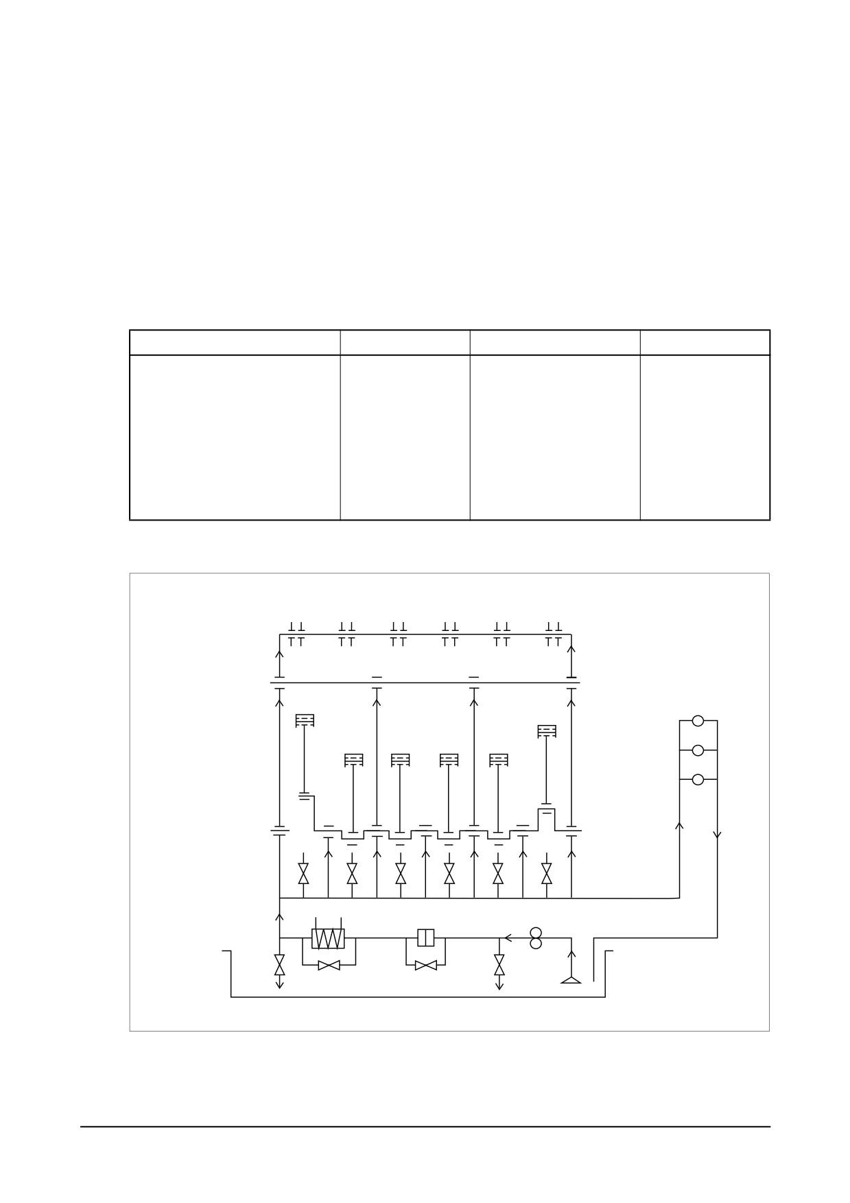
10.2.1. General descriptions and main data
● General descriptions
All the engine oil pumped up from the oil pan by the gear type oil pump is filtrated through
the oil cooler and oil filter, and this filtrated oil is forced through the main oil gallery in the
cylinder block from where it is distributed to lubricate the various sliding parts, and fuel injec-
tion pump in order to ensure normal engine performance.
● Specifications
Item
Specifications
Item
Specifications
Lubricating system
Forced pressure
Oil filter type
Full flow
circulation
Oil pump type
Gear type
Bypass for filter element
Relief valve opening pressure
10 ± 1.5 kg/cm2
Valve opening pressure
1.8 ± 2.3 kg/cm2
Bypass for oil cooler
Bypass for entire oil filter
Opening pressure
5 + 1 kg/cm2
Valve opening pressure
4.0 ~ 4.8 kg/cm2
Adjusting valve for spray nozzle
Opening pressure
1.5 ± 1.8 kg/cm2
● Diagram of lubricating system
Rocker arm
WAter pump
bearing
Fuel injection
pump
Turbocharger
Conn. rod bearing
Main bearing
Oil spray nozzle
1.3bar
Main oil gallery
Oil cooler
Oil filter
Oil pump
Relief valve
4.4bar
Valve
Valve
Valve
10bar
5bar
3bar
ED5OM008
-
118 -
Maintenance of Major Components
10.2.2. Oil pump
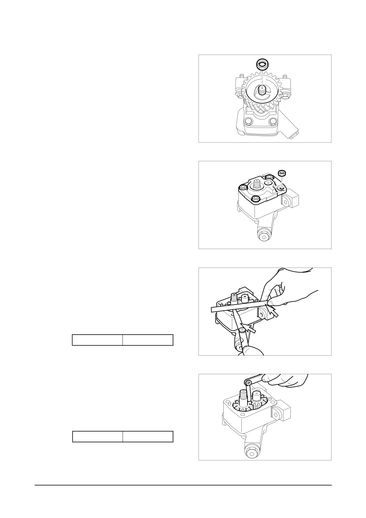
● Disassembly
1) Disassembly of oil pump drive
gear
a) Unscrew the screw and disas-
semble the oil relief valve.
b) Unfold the washer for the oil
pump drive gear fixing nut and
remove the nut.
c) Disassemble the drive gear.
EQM4006I
2) Remove the oil pump cover fixing
nuts and disassemble the oil
pump cover.
The oil pump cover is fixed with
the two dowel pins.
3) Disassemble the drive gear and
driven gear.
EQM4007I
● Inspection and correction
1) With steel rule and feeler gauge,
measure the axial end play of the
oil pump gear. Replace if the
measured value is beyond the
limit.
Steel plate
(mm)
Feeler gauge
End play
0.025 ~ 0.089
EQM4008I
2) With a feeler gauge, measure the
amount of backlash between the
oil pump drive gear and driven
gear. Replace if the measured
value is beyond the limit.
(mm)
Backlash
0.50 ~ 0.64
EQM4009I
Maintenance of Major Components
-
119 -
3) Measuring
clearance
between
drive shaft and bushing
a) Measure the outside diameters
of the drive shaft and driven
shaft, and replace if the mea-
sured values are less than the
limit.
(mm)
Limit
൵16.95
b) Measure the inside diameter of
the pump body bushing to deter-
mine the clearance between the
bushing and shaft, and compare
the measured value with the
standard value to determine
whether to replace or not.
(mm)
Clearance
0.032 ~ 0.077
● Reassembly
1) For reassembly, reverse the disas-
sembly sequence.
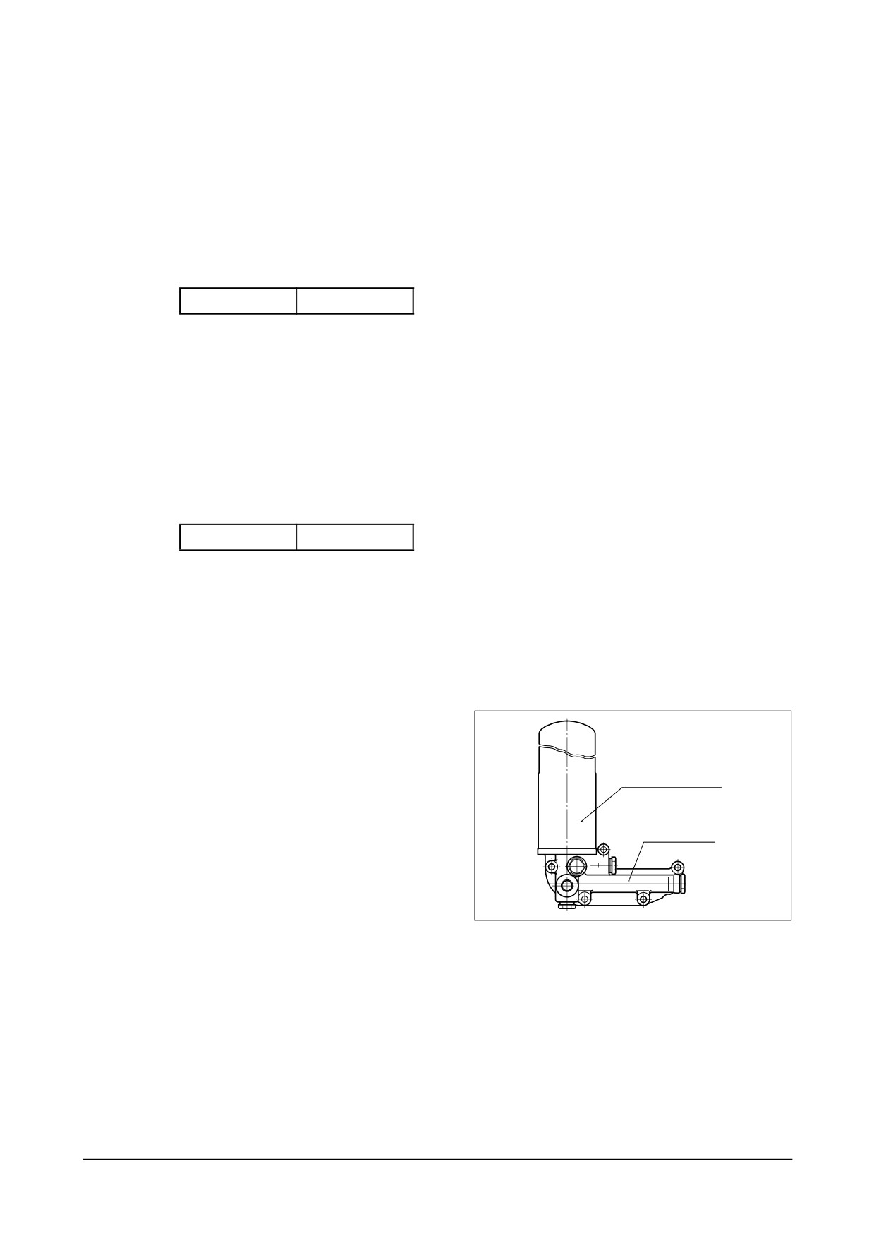
10.2.3. Oil filter
The oil filter mounted in this engine is of
cartridge type, so it is necessary to
replace it with a new one at the speci-
Oil filter (Cartridge)
fied intervals.
Oil filter head
EQM4010I
-
120 -
Maintenance of Major Components

10.2.4. Diagnostics and troubleshooting
Complaints
Possible causes
Corrections
1. Oil consumption
● Poor oil
● Use suggested oil
excessive
● Oil seal or packing leaky
● Replace
● Pistons or piston rings worn
● Replace pistons and/or piston
● Cylinder liner worn
rings
● Piston rings sticking
● Replace cylinder liner
● Valve guide oil seals or valve
● Replace pistons and/or piston
guides, or valve stem worn
rings
● Replace
2. Oil pressure too low
● Poor oil
● Use suggested oil
● Relief valve sticking
● Replace
● Restrictions in oil pump
● Clean strainer
strainer
● Replace
● Oil pump gear worn
● Replace
● Oil pump feed pipe cracked
● Correct or replace
● Oil pump defective
● Correct or replace
● Oil pressure gauge defective
● Replace
● Various bearings worn
3. Oil deteriorates quickly
● Restriction in oil filter
● Replace filter element
● Gases leaking
● Replace piston rings and cylinder
● Wrong oil used
liner
● Use suggested oil
Maintenance of Major Components
-
121 -
10.3. Fuel Injection Pump
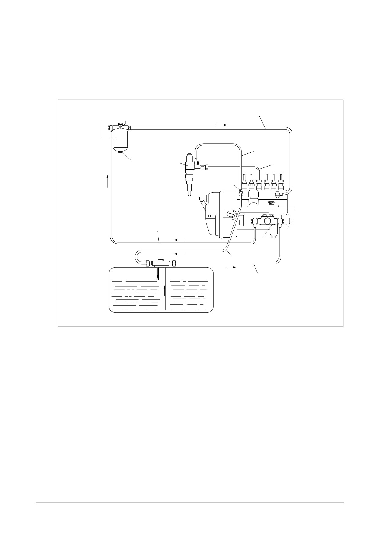
10.3.1. General information of fuel system
The fuel system consists of the fuel tank, injection pump, injection nozzle, fuel filter, and fuel
lines such as pipes and hoses necessary to connect those components.
5
1
2
4
1a
3
7
6
13
8
12
10
9
11
EA8O3004
1. Fuel filter
7. Delivery pipe
1a. Fuel water drain plug
8. Fuel pipe (manual pump → filter)
2. Air bleeding screw (for fuel filter)
9. Fuel tank
3. Injection nozzle
10. Fuel return pipe
4. Overflow tube
11. Suction pipe
Fuel pipe (filter → injection
5.
12. Feed pump
pump)
6. Overflow valve
13. Injection pump
-
122 -
Maintenance of Major Components
10.3.2. Injection pump
The components relating to the injection pump should be serviced at regular intervals as the
plunger and delivery valve may be worn after a given length of time for use and cause the
deterioration of the engine.
Make sure that servicing should be performed at the professional maintenance shop as autho-
rized by Bosch or Zexel Company.
For adjustment of fuel injection volume, refer to the 'Specifications of fuel injection pump’
described on the following pages.
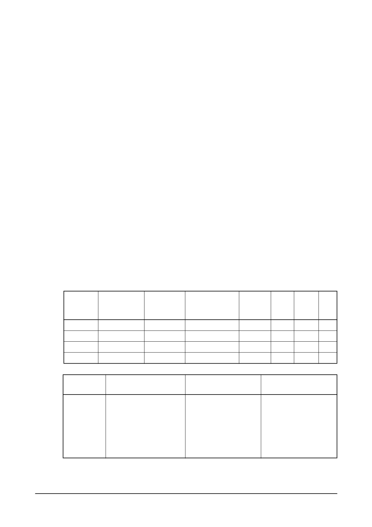
1)
DE12T
(1) Main data and specifications
Part No.
:
65.11101-7222 (106672 - 9920)
Model
: NP-PE6P120/720RS3000 (106061 - 7250)
Governor
: NP-EP/RSV200-1200PD36C311 (105407 - 4720)
Timer
: without timer
Plunger
:൵12, right hand helix 30 lead
Delivery valve
:120 mm3/st (൵8 x 2.4 mm)
Fuel feed pump
: NP-FP/K-P (105207 - 1400)
Pre-stroke
:
4.7 mm
(2) Nozzle holder assembly
:
65.10101 - 7300 (105160 - 4351)
(3) Nozzle
:
65.10102 - 6046 (105029 - 1330)
(4) Injection pipe
:
65.10301 - 7004B
(5) Injection order
:
1 - 5 - 3 - 6 - 2 - 4
(6) Injection timing
: BTDC 12C
(7) Calibration data
Pump
Adjusting
Rack position
Injection volume
Variation
Basic
Fixing
speed
Ref.
point
(rpm)
(mm3 / 1,000 st)
rate (%)
point
point
(rpm)
A
10.8
900
129 ± 2
± 2
B
11
875
(135) ± 3
C
Approx. 6.4
250
14.5 ± 1.5
± 15
D
-
10
193.5 ± 10
Adjusting
Content
Specification
Engine Application
point
Nozzle holder assembly
105780 - 8140
65.10101 - 7300
Nozzle
105780 - 0000
65.10102 - 6046
Nozzle holder
105780 - 2080
-
Adjusting
Opening pressure
175 kg/cm2
220 kg/cm2
conditions
Injection pipe
൵8 x ൵3 - 600 mm
൵6 x ൵2.2 - 650 mm
Fuel delivery pressure
1.6 kg/cm2
-
Fuel temperature
35 ~ 45 C
35 ~ 45 C
Maintenance of Major Components
-
123 -
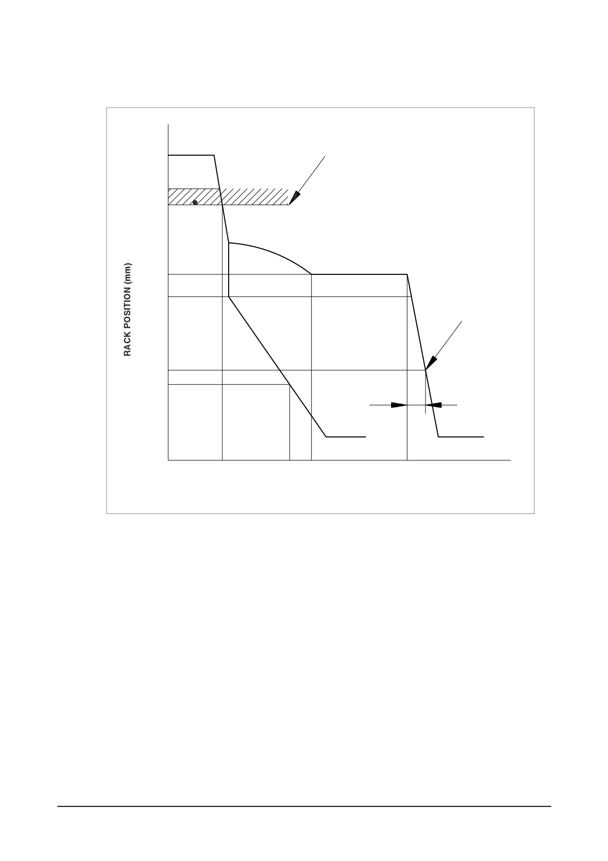
(8) Governor adjustment
Rack limit
over 14
D
11.0
B
10.8
A
Idle spring
Set : 6.5-0.5 mm
6.5
6.4
C
45 -1
0
0
250 400+20
900±5
PUMP SPEED (rpm)
EA8M4001
-
124 -
Maintenance of Major Components
2)
P126TI / P126TI-1 / P126TI-II
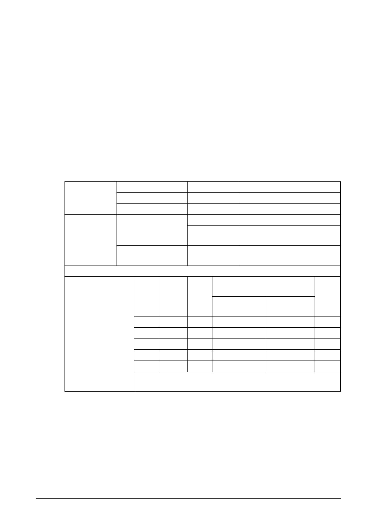
(1) Main data and specifications
Part No.
:
65.11101 - 7310 (106674-4130 ZEXEL)
Model
: NP-PE6P120/700RS3S (106067-6020)
Governor
: Ghana Control (DWA-2000)
Plunger & barrel
:
൵12, right hand double helix 30 lead
Delivery valve
:
90 mm3/st (൵7 x 2.35 mm)
Fuel feed pump
: NP-FP/KD-PS (105237 - 5470)
Pre-stroke
:
3.9 ± 0.05 mm
(2) Nozzle holder assembly
:
65.10101 - 7101 (105101 - 852A)
(3) Nozzle
:
65.10102 - 6073 (105025 - 285A)
(4) Injection pipe
:
65.10301 - 6042A, 65.10301 - 6043A
(5) Injection order
:
1 - 5 - 3 - 6 - 2 - 4
(6) Injection timing
: P126TI (BTDC 16°) / P126TI-1 (BTDC 12°)
Nozzle & Holder Ass’y
105101-852A
Opening pressure : 175 kg/cm2
(A) Test condition
for injection
Injection pipe (ID ,OD ,L)
-
൵3.0 x ൵8.0 - 600 mm
pump
Test oil
ISO4113
Temperature :40 ± 5 C
65.10101-7101
Nozzle (5 x൵ 0.37)
(B) Engine
Nozzle & holder Ass’y
1st pressure : 160 kg/cm2
65.10102-6073
standard
2nd pressure : 220 kg/cm2
parts
65.10301-6042A
Injection pipe (ID, OD ,L)
൵2.2 x ൵6.35 - 650mm
65.10301-6043A
Rack diagram and setting valve at each point
Injection Q’ty on RIG
Rack
Pump
Check
(mm3 / 1,000 st)
Press.
position
speed
point
(A) Test condition
(B) Engine
(mmHg)
(mm)
(rpm)
for inj. pump
standard parts
B
900
260 ± 2
-
Standby power
-
-
-
-
-
-
-
-
-
-
-
-
-
-
-
-
-
-
-
-
-
-
-
-
Maintenance of Major Components
-
125 -
3)
P126TI (EDIOE)
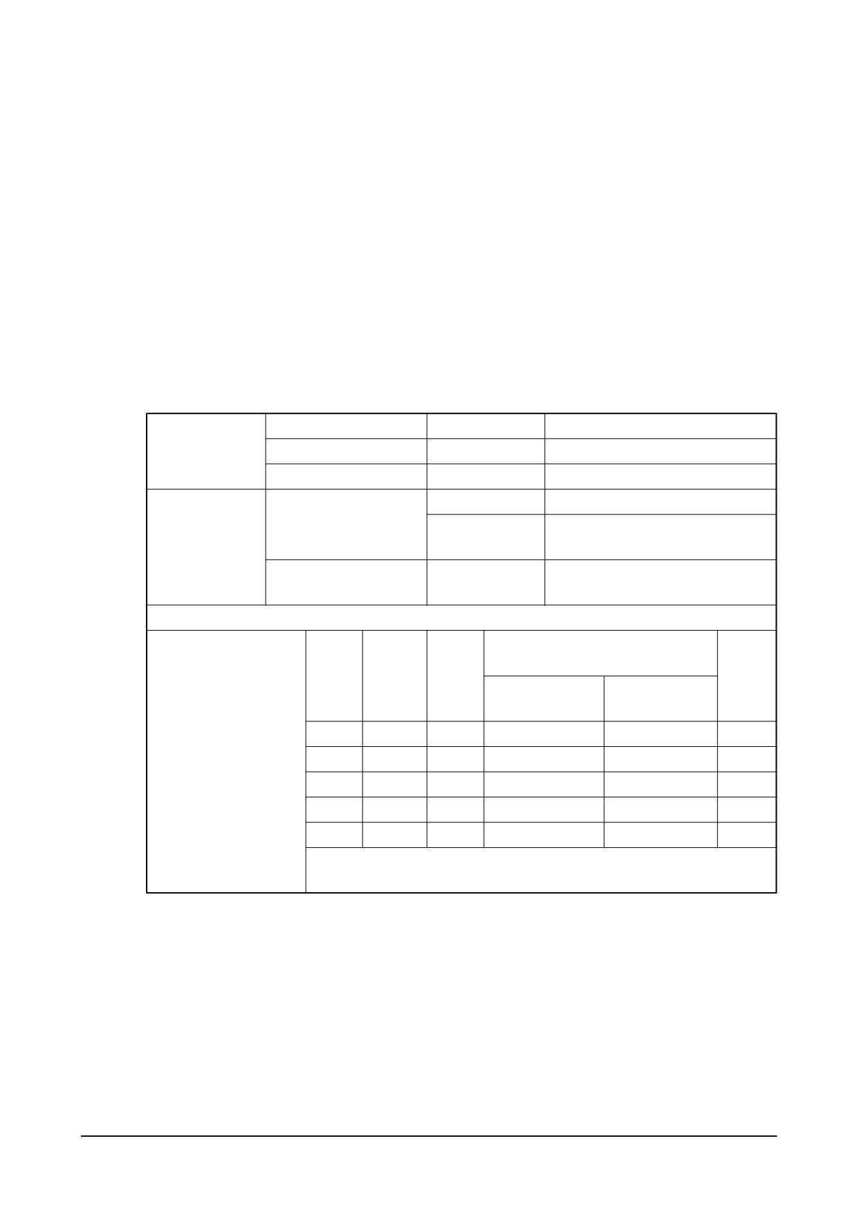
(1) Main data and specifications
Part No.
:
65.11101 - 7310 (106674 - 4130 ZEXEL)
Model
: NP-PE6P120/700RS3S (106067 - 6020)
Governor
: Ghana Control (DWA-2000)
Plunger & barrel
:
൵12, right hand double helix 30 lead
Delivery valve
:
90 mm3/st (൵7 x 2.35 mm)
Fuel feed pump
: NP-FP/KD-PS (105237 - 5470)
Pre-stroke
:
3.9 ± 0.05 mm
(2) Nozzle holder assembly
:
65.10101 - 7104 (105101 - 853A)
(3) Nozzle
:
105025 - 291A
(4) Injection pipe
:
65.10301 - 6042A, 65.10301 - 6043A
(5) Injection order
:
1 - 5 - 3 - 6 - 2 - 4
(6) Injection timing
: BTDC 16°
Nozzle & Holder Ass’y
105101-853A
Opening pressure : 175 kg/cm2
(A) Test condition
for injection
Injection pipe (ID ,OD ,L)
-
൵3.0 x ൵8.0 - 600 mm
pump
Test oil
ISO4113
Temperature :40ٻC ± 5 C
65.10101-7104
Nozzle (5 x൵ 0.35)
Nozzle & holder Ass’y
1st pressure : 160 kg/cm2
(B) Engine
-
2nd pressure : 220 kg/cm2
standard parts
65.10301-6042A
Injection pipe (ID, OD ,L)
൵2.2 x ൵6.35 - 650mm
65.10301-6043A
Rack diagram and setting valve at each point
Injection Q’ty on RIG
Rack
Pump
Check
(mm3 / 1,000 st)
Press.
position
speed
point
(A) Test condition
(B) Engine
(mmHg)
(mm)
(rpm)
for inj. pump
standard parts
B
900
260 ± 2
-
Standby power
-
-
-
-
-
-
-
-
-
-
-
-
-
-
-
-
-
-
-
-
-
-
-
-
-
126 -
Maintenance of Major Components
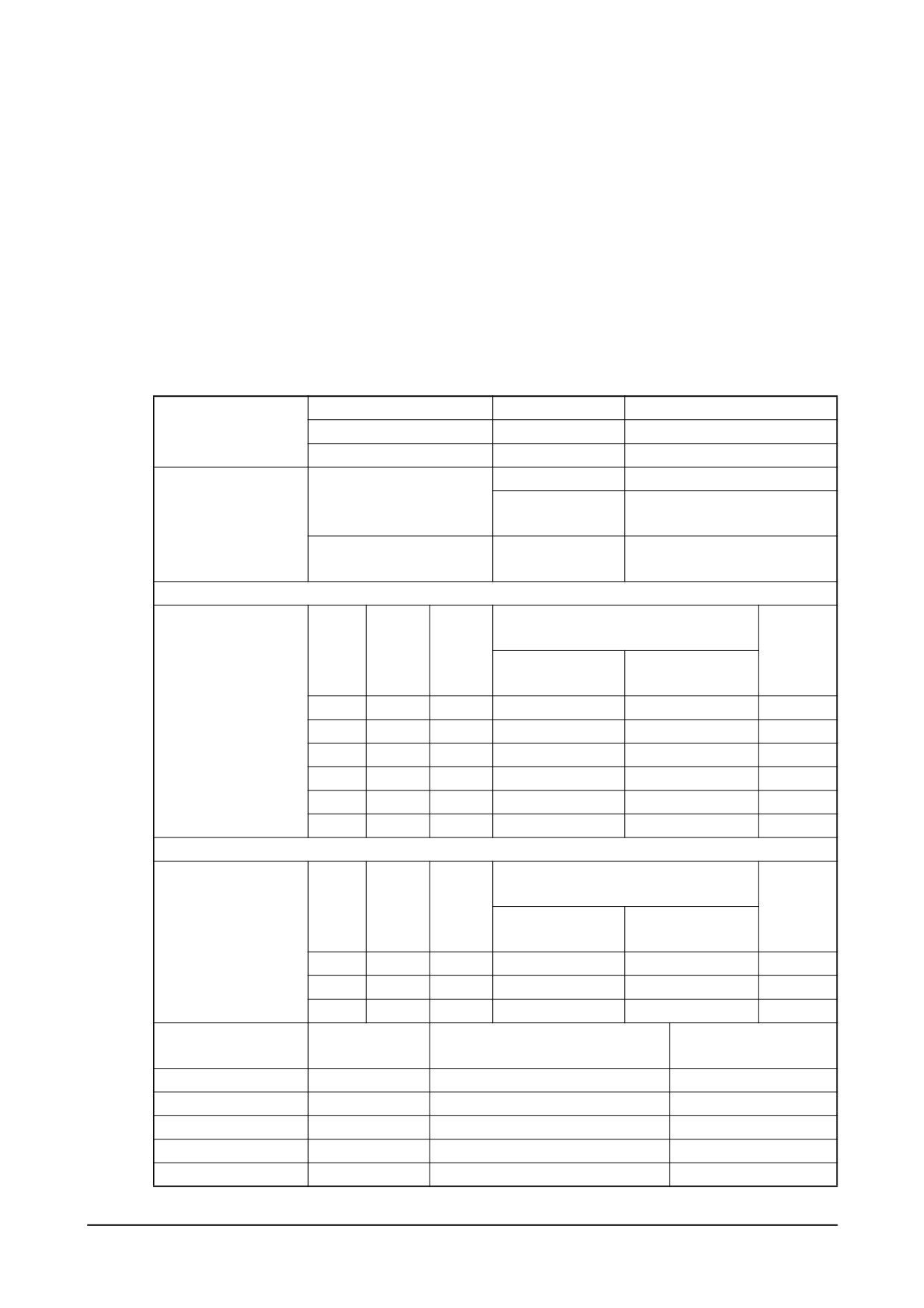
4) PU126TI
(1) Main data and specifications
Injection pump
:
65.11101 - 7310 (106674 - 4130 ZEXEL)
Model
: NP-PE6P120/700RS3S (106067 - 6020)
Governor
: Ghana Control (DWA-2000)
Fuel feed pump
: NP-FP/KD-PS (105237 - 5470)
Cam Lift
:
12 mm
Injection timing
: BTDC 14° ± 1
Injection order
:
1 - 5 - 3 - 6 - 2 - 4
Rotating Direction
: Clockwise (Viewed at driving gear side)
Pre-stroke
:
3.9 ± 0.05 mm
(2) Calibration data
Nozzle & Holder Ass’y
105101-8530
Opening pressure : 175 kg/cm2
(A) Test condition for
Injection pipe (ID ,OD ,L)
-
൵3.0 x ൵8.0 - 600 mm
injection pump
Test oil
ISO4113
Temperature :40 ± 5 C
65.10101-7057
Nozzle (5 x൵ 0.40)
Nozzle & holder Ass’y
1st pressure : 160 kg/cm2
(B) Engine standard
65.10102-6050
2nd pressure : 220 kg/cm2
parts
65.10301-6043A
Injection pipe (ID, OD ,L)
൵2.2 x ൵6.35 - 650 mm
65.10301-6042A
Rack diagram and setting valve at each point
Injection Q’ty on RIG
Rack
Pump
Check
(mm3 / 1,000 st)
Press.
position
speed
point
(A) Test condition
(B) Engine
(mmHg)
(mm)
(rpm)
for inj. pump
standard parts
Refer to (3)
A
12.5
1,000
187 ± 2
-
≤ 675
Rack Diagram
B
6.1
350
10 ± 1.5
-
-
C
12.5
500
-
≤ 675
D
11.9
500
-
-
E
7.5
1,100
-
-
250
-
Boost pressure dependent full-load stop (boost compensator spring operation point)
Injection Q’ty on RIG
Rack
Pump
Check
(mm3 / 1,000 st)
Press.
position
speed
point
(A) Test condition
(B) Engine
(mmHg)
Refer to (4)
(mm)
(rpm)
for inj. pump
standard parts
Boost Pressure
P1
11.9
500
-
525
P2
12.5
500
-
675
-
-
-
-
-
Min. speed 1:1.2
Weight
Weight = 740 g
Lever ratio (min/max)
Max.speed 1:1.2
Governor spring
k = 70.6 mpa
Plunger
൵12, 30 lead
Idle sub spring
k = 11.8 mpa
Delivery valve retraction volume
2.45 mpa
Start spring
k = 0.098 mpa
Delivery valve opening pressure
k = 8.53 mpa
Boost compensator
k = 8.24 mpa
Delivery valve spring
105237-5470
Adapter spring
k = 63.7 mpa
Feed pump
Maintenance of Major Components
-
127 -
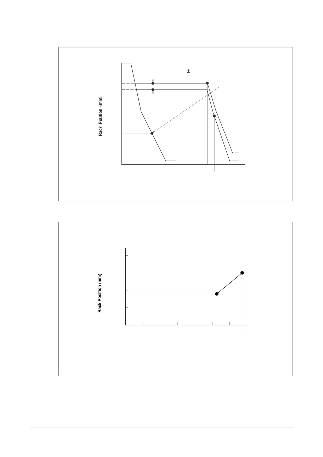
(3) Rack Diagram
16 above
BSC Stroke : 0.6 0 .1 mm
C
A
12.5
Governor Spring Se
11.9
D
7.5
E
6.1
B
0
350
1000
1100
Injection Pump Speed (mm)
EI6OM013
(4) Boost Compensator Pressure
13.1
P2
12.5
12.0
11.9
P1
11.5
11.0
0
100
200
300
400
500
600
700
525
675
Boost Pressure (mmHg)
EI6OM014
-
128 -
Maintenance of Major Components
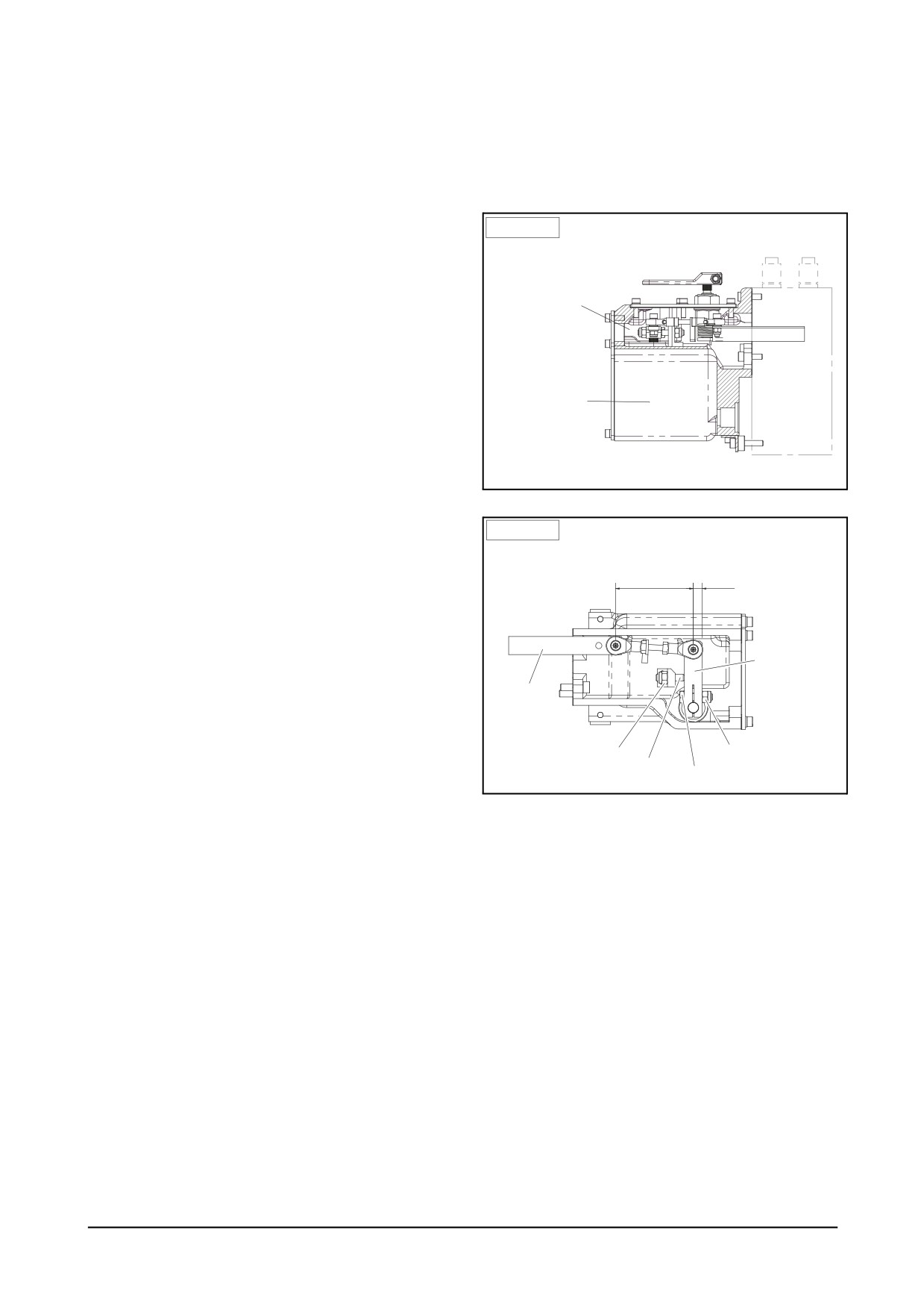
10.3.3. Governor system
10.3.3.1. Actuator
● Actuator Component Parts Function
1. Emergency stop lever: The manual engine stop lever
Side view
when emergency.
Emergency
2. Upper control chamber: The cover is install for inside
stop lever
control.
Upper control chamber
3. Electronic control chamber: The electronic signal oper-
(oil lubrication)
ates the operation lever. It is sealed and can not
control.
4. Adjusting screw: Adjusting screw is the controlled
Fuel
max. fuel capacity. If the length of the nut is long, the
Electronic control
injection
chamber
Pump
torque is decrease. if the length of the nut is short,
the torque is increase.
5. Fuel stop plate: The plate controls the increasing fuel
Ghana Actuator
as the preventing movement of adjusting screw.
6. Operation lever: It is the connecting lever to operate
DV2213103B
the fuel rack.
Top view
7. Fuel rack: It controls the fuel capacity of the fuel injec-
Fuel rack stop position adjustment
tion pump connected link lever.
Linkage length(L)
Fuel rack stop position
Caution: Adjusting fuel injection pump is critical part for
the enfine performance and durability. Only certi-
fied professional technicians should repair and
maintain engines.
Operating lever
Fuel rack
Lock nut
Lock nut
Stop Screw
Adjusting Screw
DV2213104B
Maintenance of Major Components
- 129 -
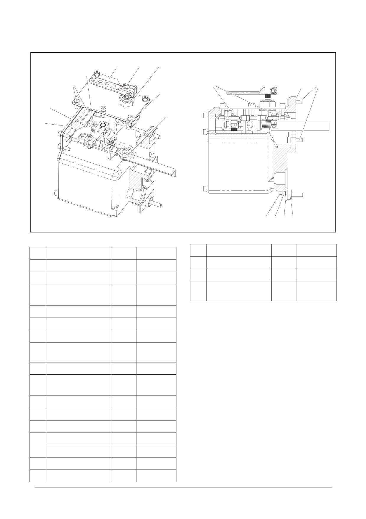
14, 15
17
18
16
13
2, 3
10
6
4, 5
11
1
12
Fuel rack
6
7
8
9
DV2213210
No
Title
Amount
Remarks
No
Title
Amount
Remarks
16
Operating Lever
1
1
Ball link ASS"Y
1
M5xL15
17
Stop Lever
1
2
Screw, Ball link
2
M5xL15
Manual Stop Device
Φ5.5x
18
1
3
Plain Washer
2
ASS'Y
Φ14xT1.2
4
Stop Screw
1
M6xL25
5
Lock Nut
1
M6xP1.0
6
Allen Screw (SEMS)
6
M6x22L
M6x30L or
7
Allen Screw (SEMS)
2
18L
8
Mounting Bar
1
Φ6.5x
9
Spacer
2
Φ16xT7.4
10
Pump Gasket
1
T 0.5
11
Front Cover
1
T 3.2
12
Front Gasket
1
T0.5
Allen Screw
8
13
Seal Screw
4
14
Top Cover
1
T 3.2
15
Top Gasket
1
T 0.5
- 130 -
Maintenance of Major Components
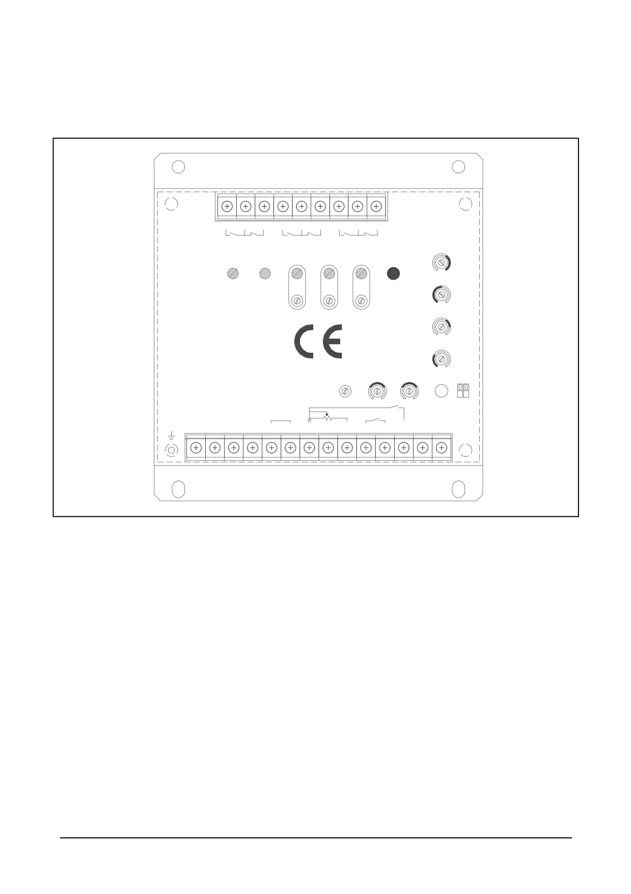
10.3.3.2. Controller system
(DGC-2013 Governor Controller System)
9
8
7
6
5
4
3
2
1
±
Crank
°
Run
¯
Over speed
Power Pick-up Crank
Run Over speed
Starting
¦
Fuel
Test
Speed
§
Ramping
¬
«
Idle
¨
Droop
£
¤ ¥
Speed Gain Stability
ON
D1
D2
OFF
Battery
Speed Trim
Droop
Idle
ª
Frame
Actuator
Pick-up
-
+
AUX
10V
GND
A B
C D E
F G H J K L
M
N
P
®
DV2213203B
Maintenance of Major Components
- 131 -
● Description
DGC-2013 Governor Controller Unit is an electronic device designed based on PID algorithm to control engine speed
with fast and precise response to transient load changes. The device is available for both single operation (Isochronous
mode) and parallel operation (Droop mode).
● Mounting & Warning
DGC-2013 Governor Controller Unit is an electronic device designed based on PID algorithm to control engine speed
with fast and precise response to transient load changes. The device is available for both single operation (Isochronous
mode) and parallel operation (Droop mode).
1. Mount the controller unit vertically to the surface of a control cabinet, protected from the weather and high humidity,
and do not expose the controller unit to the source of radiant heat. Prolonged exposure to moisture (for one month
or longer or in case condensation forms) can lead to change in the resistance of internal circuit and failure to reach
rated torque. Therefore, make sure that the controller is dry before use.
2. Do not rely exclusively on the governor system electric actuator to prevent overspeed. A secondary shutoff device,
such as a fuel solenoid must be used.
3. The setting range indicated on each menu of the control mode is the average range for each engine. It is recom-
mended to set DI engines within each indicated setting range.
EMC (Electromagnetic Compatibility)
To satisfy EMC requirements, the controller unit should be mounted on the grounded metal side, and it is required to
use shielded wires for all signal lines and ground all the shields to one of the bolts used to mount the controller.
No product with EMC-related quality issues arising from not following the above instruction will be guaranteed.
● Functions
1.
① Speed: Adjusting the engine speed
2.
② Gain: Adjusting the gain (governing sensitivity)
3.
③ Stability: Adjusting the stability (governing response)
4.
④ Starting Fuel: Adjusting the fuel amount at engine start up
5.
⑤ Speed Ramping: Adjusting the time to reach the rated speed
6.
⑥ Idle: Adjusting the idle speed
7.
⑦ Droop: Adjusting the percentage (%) of droop
8.
⑧ Dip Switch: Adjusting the dip switch
9.
⑨ Over Speed: Adjusting the point when overspeed lamp is on and the relevant relay is activated
10. ⑩ Run Lamp: Adjusting the point when run lamp is on and the relevant relay is activated
11. ⑪ Crank Lamp: Adjusting the point when crank lamp is on and the relevant relay is activated
12. ⑫ ) TB1: Terminal block for input and output
13. ⑬ TB2: Relay terminal for overspeed mode (capacity - 2A/125VAC).
14. ⑭ TB3: Relay terminal for run mode (capacity - 2A/125VAC).
15. ⑮ TB4: Relay terminal for crank mode (capacity - 2A/125VAC).
- 132 -
Maintenance of Major Components
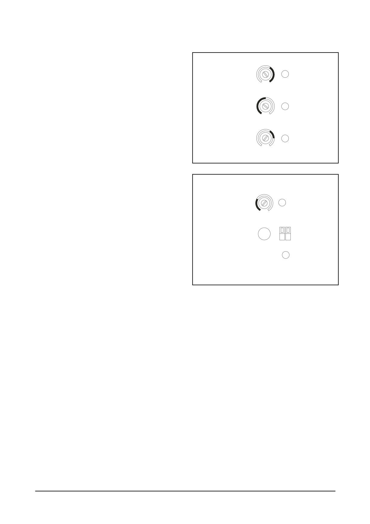
● Adjustments
1. The ranges of resistance indicated on the case are
applicable only to DI engines.
Starting
4
2. For potentiometer adjustment, use a small sized (-)
Fuel
screw driver. (Be cautious of potentiometers being
damaged)
3. Check that all electrical connections are correctly
Speed
5
made and terminal screws tightened.
Ramping
4. Engine Startup
Connect terminals G and M (with idle switch ON).
1)
(4) Starting Fuel
Idle
6
Note) Reason for adjustment: To maximize the fuel effi-
ciency of the engine
DV2213193B
* Purpose of adjustment:
Note) Recommended position: Between the 1 and 5
o’clock positions
Note) Possible problems: Between the 7 and 1 o’clock
positions
→ starting problems due to a lack of fuel
Droop
7
supply; The 5 o’clock position or above
→
decreasing fuel efficiency and increasing exhaust
ON
emissions at engine start up
D1
D2
2) Turn ⑤ Speed Ramping to between the 9 and 12
OFF
o'clock position.
Note) The time to reach the rated speed (run speed)
8
AUX
10V
prolongs as turning ⑤ Speed Ramping clockwise
(max. over 10 sec)
DV2213193C
Note) With ⑤ Speed Ramping biased to counterclock-
wise direction, a symptom of overshoot or hunting
can occur.
3) Start cranking the engine.
5. Rated speed & Idle speed
1) Rated speed adjustment.
Note) After engine startup, remove the connection
between terminals G and M (with idle switch OFF)
Note) Under no load condition, adjust Speed. Clockwise):
RPM increase/counterclockwise RPM decrease
2) Idle speed adjustment
Note) With idle switch ON again, set the engine speed
at 800 rpm by ⑥ Idle potentiometer.
Note) Reason for adjustment: To adjust pre-heat levels
after engine start up or the initial fuel amount at
engine start up
Note) Recommended position: Between the 12 and 3
o'clock positions. Though varying by engine model
or rated RPM, it is recommended to set the RPM
as 800RPM.
Note) Possible problems: Decreasing cold start perfor-
mance and the excessive use of fuel during the
warm-up phase.
Maintenance of Major Components
- 133 -
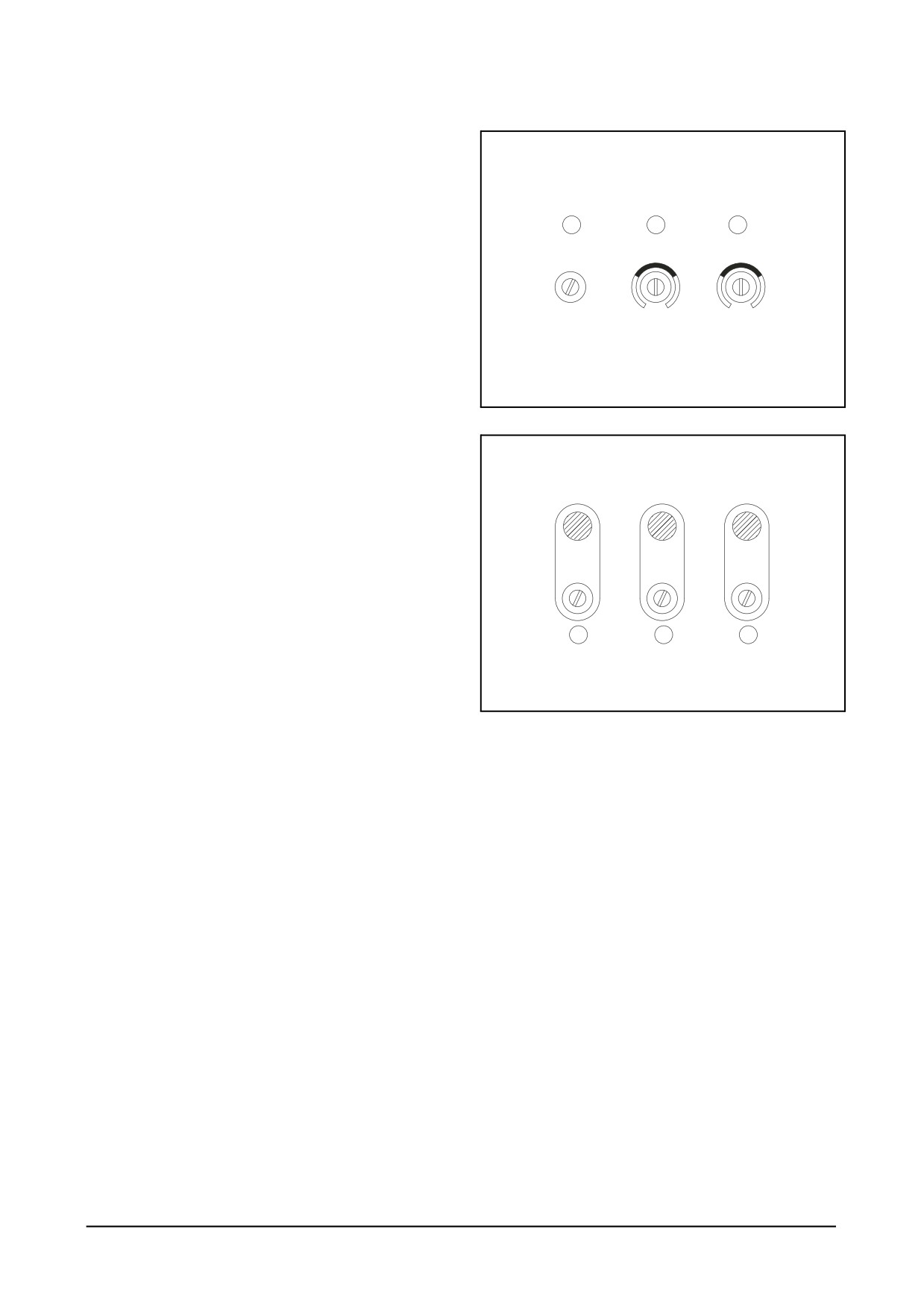
Caution: Idle speed is one of the important factors to
determine the characteristics of engine startup. Therefore,
it is necessary to adjust the idle speed after rated speed
adjustment regardless of the use of "idle mode."
6. Governor performance adjustment
1
2
3
1) Remove the connection between terminals G and M
(with idle switch OFF). Once the engine reaches run
Speed
Gain
Stability
speed, adjust the performance of governor.
2) Gain adjustment.
Note) Turn ② Gain clockwise until instability develops at
no load.
Note) Gradually move ② Gain counterclockwise until
stability returns.
DV2213196B
Note) Move ② Gain counterclockwise further by around
20 minutes (10°) to ensure stable performance.
7. Stability adjustment.
1) Turn ③ Stability clockwise at no load until instability
Crank
Run
Over speed
develops.
2) Gradually move ③ Stability counterclockwise until
stability returns.
3) Move ③ Stability counterclockwise further by around
20 minutes (10°) to ensure stable performance.
8. Accessory adjustment
11
10
9
1) Run Lamp ON
Note) At the rated speed, turn ⑩ Run counterclockwise
until the Run Lamp is on.
DV2213196C
Note) Move ⑩ Run counterclockwise further by 90° to
prevent the Run Lamp from flickering.
2) Crank Lamp ON
Note) At the idle speed, turn ⑩ Crank counterclockwise
until the Crank Lamp is on.
Note) Move ⑩ Crank counterclockwise further by 90° to
prevent the Crank Lamp from flickering.
3) Overspeed Lamp ON
Note) At the rated speed, as pressing the Test button,
gradually turn ⑨ Over Speed counterclockwise
until the Overspeed Lamp is on and the engine is
shut off simultaneously.
Note) With the adjustment above, the overspeed function
is triggered at around 115% of the rated speed.
Caution: On completion of all the adjustments, start up
the engine again to ensure the stable operation
at engine startup, at no load, and at load oper-
ation, respectively.
- 134 -
Maintenance of Major Components
9. Starting Fuel Adjustment (to minimize the engine's
exhaust smoke)
1) Turn on idle speed switch
→ Set the idlespeed at
800RPM → Turn ④ Starting Fuel counterclockwise
until the engine speed begins to fall
→ Move ④
tarting Fuel clockwise further by 15° to stabilize the
engine speed.
Caution: In case the exhaust smoke is not thick, It is
recommended to place (4) Starting Fuel at the
5 o'clock position. If (4) Starting Fuel is set too
low, It may be hard to start the engine and
cause the speed overshoot on engine startup,
even resulting in exceeding the preset over-
speed value.
10. When the engine won’t start
1) If there is no wrong wiring
→ Return all adjustments
to the "factory-set values"
→ Start up the engine
again.
Maintenance of Major Components
- 135 -
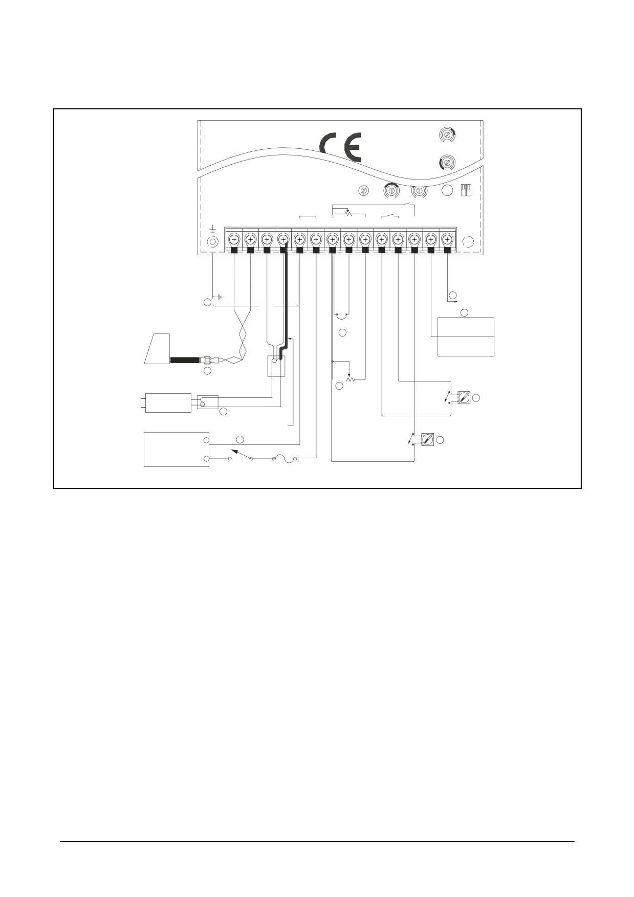
● External Wiring
Idle
Droop
Speed
ON
D1
D2
OFF
Battery
Speed Trim
Droop
Idle
Frame
Actuator
Pick-up
-
+
AUX
10V
GND
A B C D E F G H J
K L
M
N
P
9
10
10V POWER
8
Actuator
Jumper
Load sharing
5
unit
Auto
synchronizer
<Auxiliary unit>
1
1.5߮
2C
2
3
1
4
5ࠗ
Magnetic
7
Pick-up
2
1.5߮
2C shield
Droop switch
shield cable(cover with insulation tube)
3
1.5߮
2C
6
BATTERY
Idle switch
24V
-
Power switch Fuse(10A)
DV2213211A
•
Wiring to the speed control unit should be as shown in DV2213211A.
•
All the cables should be 1.5mm2 or larger and shielded cables should be used for all external connections.
•
Other shielded cables not described in DV2213211A should be grounded to the frame.
1.
Twisted cables should be used for actuator connections. The normal reading of resistance between terminals A &
B should be between 3.5Ω and 4.5Ω.
2.
Magnetic speed sensor connections to terminals C and D must be shielded for their entire length. The speed sensor
cable should only be connected to terminal D. The shield should be insulated to ensure no other part of the shield
comes in contact with engine ground. Otherwise, stray speed signals may be introduced to the speed control unit
resulting in instability, etc.
3.
Be cautious that the battery's polarity to terminals E and F should not be switched and a 10 amp fuse must be
installed between battery (+) and terminal F. After the wiring work, check the voltage between terminals which should
be 24VDC (±4V). Ground the terminal E to the frame (wiring (10)).
4.
As illustrated in DV2213211A, connecting the optional 5k Ω resistance enables fine adjustment of engine speed within
the range of preset speed ±210Hz range.
5.
In case of 12V system, or of actuator with current consumption over 5 amp or above, connect terminals G and H.
6.
Selector switch, switching over "IDLE mode" and "RUN mode" ON (close): idle mode OFF (open): run rated mode
7.
"DROOP" mode selector switch ON (close): DROOP mode OFF (open): Isochronous mode
8.
The signal from Auxiliary device for parallel operation system should be connected to terminal N. It is necessary to
use the shielded cable for the signal.
9.
Accessory power supply: The +10[V] and 20[mA] of current supply, Terminal P, can be utilized to provide power to
governor system accessory and for various other purposes
Caution: Wrong or erroneous wiring and battery voltage can cause fatal damage to the controller.
- 136 -
Maintenance of Major Components
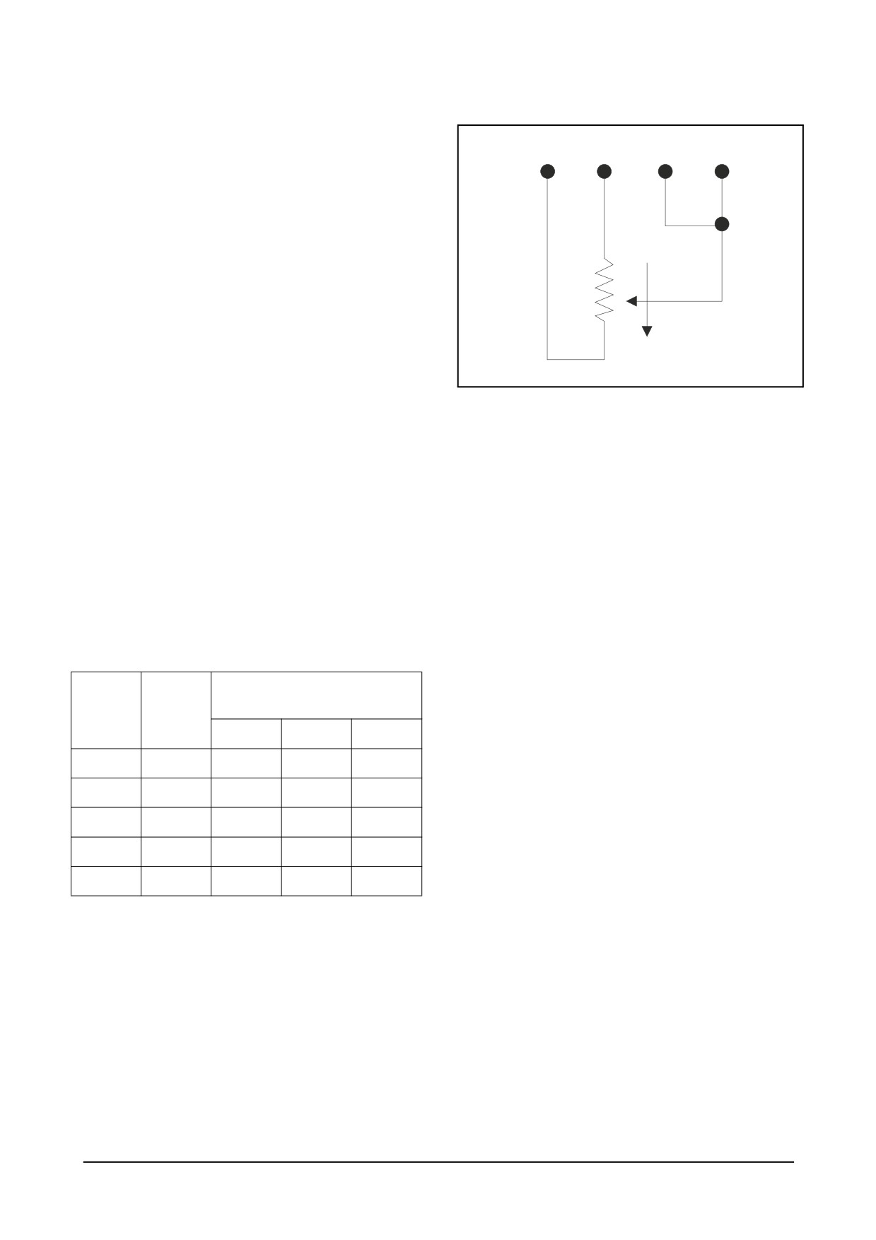
● Magnetic speed sensor connections
1. With the engine stopped, adjust the gap between the
G
J
K
L
magnetic speed sensor and the ring gear teeth. The
gap should not be any smaller than 0.45mm. Usually,
backing out the speed sensor by 3/4 turn after
touching the ring gear teeth will achieve a satisfactory
air gap.
2. The signal from the speed sensor can be measured
between C and D in engine operation.
3. Signal VAC 3 or above is required for the controller.
● Remote speed adjustment
CW
1. As illustrated in DV2213106A, a remote speed adjust-
DV2213106A
ment potentiometer can be used to adjust the engine
speed over specific speed range. Select the desired
speed range and the corresponding potentiometer
value. When the minimum speed setting is used in
remote adjustment mode, the speed drop phenom-
enon may occur due to instability and load in the
system. To maintain engine stability at the minimum
speed setting above, a small amount of droop can be
added by turning ⑦ Droop counterclockwise. On the
other hand, at the maximum speed setting, the
governor performance will be near Isochronous
regardless of the droop adjustment setting
2. Potentiometer Value by Speed Range
Engine RPM for Each Ring
Pote
Speed
Gear
tiometer
range
value
160 teeth
152 teeth
146 teeth
900Hz
1K
337rpm
355rpm
370rpm
2,400Hz
5K
900rpm
947rpm
986rpm
3,000Hz
10K
1,125rpm
1,184rpm
1,230rpm
3,500Hz
25K
1,315rpm
1,381rpm
1,438rpm
3,700Hz
50K
1,387rpm
1,460rpm
1,520rpm
Maintenance of Major Components
- 137 -
3.
Factory-set Value
300611-00685
300611-00683
1,725rpm (No. of teeth =
Overspeed
1,725rpm (No. of teeth =
152)
Overspeed
160)
Run lamp
Maximum CW
Run lamp
Maximum CW
Gain
Mid-range (12 O’clock)
Gain
Mid-range (12 O’clock)
Stability
Mid-range (12 O’clock)
Stability
Mid-range (12 O’clock)
Starting Fuel
Full CWa(Maximum Fuel)
Starting Fuel
Full CWa(Maximum Fuel)
Speed Ramping
9 O’clock
Speed Ramping
9 O’clock
Droop
Full CCWb
(Minimum)
Droop
Full CCWb (Minimum)
Adjustment
(No. of teeth = 160)
Adjustment
(No. of teeth = 160)
Speed Adjustment
3,800Hz (1500rpm)
Speed Adjustment
4,000Hz (1500rpm)
Idle Adjustment
2,026Hz (800rpm)
Idle Adjustment
2,133Hz (800rpm)
a.
CW: Clockwise
b.
CCW: Countclockwise
a.
CW: Clockwise
b.
CCW: Countclockwise
300611-00686
300611-00684
2,070rpm (No. of teeth =
Overspeed
2,070rpm (No. of teeth =
152)
Overspeed
160)
Run lamp
Maximum CW
Run lamp
Maximum CW
Gain
Mid-range (12 O’clock)
Gain
Mid-range (12 O’clock)
Stability
Mid-range (12 O’clock)
Stability
Mid-range (12 O’clock)
Starting Fuel
Full CWa(Maximum Fuel)
Starting Fuel
Full CWa(Maximum Fuel)
Speed Ramping
9 O’clock
Speed Ramping
9 O’clock
Droop
Full CCWb
(Minimum)
Droop
Full CCWb (Minimum)
Adjustment
(No. of teeth = 160)
Adjustment
(No. of teeth = 160)
Speed Adjustment
4,053Hz (1800rpm)
Speed Adjustment
4,800Hz (1800rpm)
Idle Adjustment
2,026Hz (800rpm)
Idle Adjustment
2,133Hz (800rpm)
a.
CW: Clockwise
b.
CCW: Countclockwise
a.
CW: Clockwise
b.
CCW: Countclockwise
- 138 -
Maintenance of Major Components
● Droop parallel Operation mode (Manual paralleling)
• Definition: Engine speed on the decrease against Engine load on the increase.
DROOP(%) = {(No Load Speed - Full Load Rated Speed) x 100} / Full Load Rated Speed
• Description: Droop is typically used for the load sharing and paralleling of engine driven generators. Without the
Droop mode in paralleling system, generators can be overloaded or motorized.
• Application: For DROOP Operation,
1. Close Droop selector switch between terminals K and L.
2. When in Droop operation, the engine speed will decrease as engine load increase. The percentage of droop
governing can be varied with ⑦ Droop potentiometer. The higher level of droop is achieved as turning ⑦ Droop
clockwise.
• Droop level requirements above 10% are unusual and the minimum droop level to keep the stability of speed droop
governor is 2.5% or above.
• After the droop level has been adjusted, the rated engine speed setting may need to be reset. Check the engine
speed and adjust the speed setting accordingly.
● Accessory Input (Automatic Paralleling)
• The Auxiliary terminal N accepts input signals from load sharing units, auto synchronizers, and other governor system
accessories.
• It is recommended that this connection from accessories be shielded as it is a sensitive input terminal.
• When an accessory is connected to Terminal N, the speed will decrease and the speed adjustment must be reset.
• When operating in the upper end of the control system frequency range, a jumper wire or frequency trim control
may be required between Terminals G and J. This increases the frequency range of the speed control to over
7,000Hz.
● Controller LAMP Display (diagnosis)
• Power : When the battery power is connected and inner control power (DC 12V) is achieved, the lap is on and
main controller is ready to function.
• Pick Up : When the voltage between terminals C and D is VAC 3.0 or above, the lamp is on.
• Crank : When the engine reaches the preset rated speed (idle speed), the lamp is on and relevant relay is achieved.
• Run : When the engine reaches the preset rated speed (operating speed), the lamp is on and relevant relay is
achieved.
• Over Speed : When the engine reaches the preset overspeed, the lamp is on and relevant relay is activated and
the power to the actuator is shut off.
● System Troubleshooting (Instability)
1. Fast instability
(Hunting)
1) When the position of switch D1 is ON, the differential function is activated.
2. It provides fast transient response against engine speed changes.
3. However, it may generate fast instability being sensitive to external high frequency noise. In this case, place the
switch D1 to OFF position and readjust ② Gain and ③ Stability.
4. If instability should be still present, placing D2 to OFF position may help stabilize the engine. Again, readjust ②
Gain and ③ Stability for optimum control.
5. Slow instability (Hunting)
Slow instability can have many causes, most of which are due to wrong setting against the engine characteristics.
Adjustment of ② Gain and ③ Stability usually cures most situations
6. If the troubleshooting above is not successful
1) Due to the controller at fault - Replace the controller with new one.
2) Due to the external devices at fault (Actuator, fuel injection device, turbine, etc) rectify the mechanical devices.
Maintenance of Major Components
- 139 -
● System inoperative
If the engine governing system does not function, the fault may be determined by performing the voltage tests described
in steps 1, 2 and 3. (+) and (-) refer to meter polarity. If normal values should be indicated as a result of following
the troubleshooting steps, the fault may be with the actuator or the wiring to the actuator. In that case, check the
actuator.
When to Take
Normal read-
Step
Terminal
Probable Cause of Abnormal Reading
Solution
the Reading
ings
1. Check battery line
When the
1
F(+) & E(-)
DC 24V
engine stopped
2. Replace battery
1. Low battery voltage
1. Check battery line
When starting
DC 15V or
2
F(+) & E(-)
the engine
above
2. Wiring error
2. Replace battery
1. Defective speed sensor
1. Check sensor line
300~1200Ω
When the
3
C & D
(tester ohmme-
engine stopped
2. Improper or defective wiring to the
2. Replace speed sensor
ter)
speed sensor
1. The gap between speed sensor and
1. Check sensor line
1.5V or above
gear teeth too great.
When starting
4
C & D
(tester AC volt-
the engine
meter)
2. Replace speed sen-
2. Defective speed sensor
sor
1. If the voltage reading is below
1. Check short/open
3.8 Ω => Short
actuator
When the
3.8~4.5 Ω (tes-
5
A & B
2. If the voltage reading is above
engine stopped
ter ohmmeter)
4.8 Ω => Open wire
2. Replace actuator
3. Defective actuator
6
P(+) & G(-)
KEY S/W ON
DC 9.5~10.5V
Defective speed controller
Replace controller
1. Speed adjustment set too low.
1. Check speed setting
DC 9~15V in
normal condi-
2. Short/open in actuator wiring
2. Check actuator line
When starting
7
F(+) & A(-)
tions DC 1~3V
the engine
3. Replace actuator
in abnormal
3. Actuator
when found to be
conditions
defective
- 140 -
Maintenance of Major Components
10.3.4. Fuel feed pump
1) General descriptions and construction
Priming pump
Check valve
Check valve
Outlet
Inlet
side
side
Tappet
Piston
Cam shaft
EQM4019I
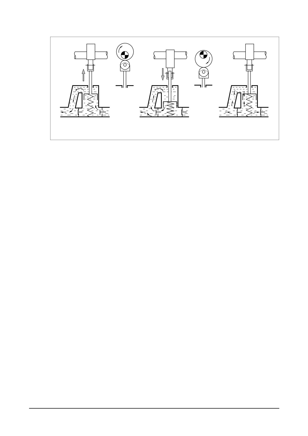
The P-type injection pump is mounted with K-ADS or KP type feed pump. These pumps have the
same basic construction and operation, and the general descriptions of the KP type pump are
given below:
The figures show its construction (right figure) and operation (below figure). The piston in the fuel
feed pump is driven by the push rod and tappet via the camshaft of injection pump and performs
reciprocating operation to control the suction and delivery of fuel. When the cam reaches the Bot-
tom Dead Center as shown in the figure, the fuel is drawn in through the check valve on the inlet
side.
The fuel pressurized as the cam rotates on flows through the check valve on the outlet side as
shown in (B). If the feeding pressure increases abnormally, the spring is compressed, resulting in
interrupting further delivery of fuel as shown in (C).
Maintenance of Major Components
- 141 -
(A)
(B)
(C)
Inlet side
Outlet side
Interruption
EQM4020I
This feed pump is mounted with a priming pump designed to permit manual feeding of fuel from the
fuel tank with the injection pump mounted in the engine. During the manual feeding operation, air
must be bled from the fuel lines.
When using the priming pump, fix it securely to prevent the possible entry of moisture or other for-
eign substances in the inside of feed pump.
In addition, a strainer is fitted into joint bolt on the inlet side of the fuel feed pump to filtrate any for-
eign substances possibly mixed in fuel.
- 142 -
Maintenance of Major Components
2) Disassembly
42
25
16
18
20
10
18
15
15
14
14
Fuel tank side
strainer bolt (MESH 50)
30
35
32
1
5
36
6
32
8
7
EQM4021S
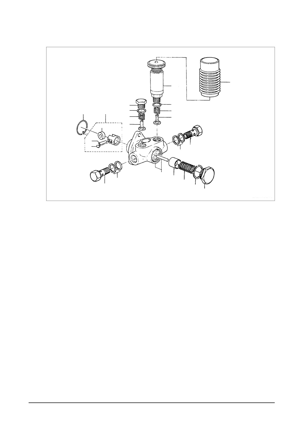
● Clamp the feed pump with a vise and disassemble the plugs (30, 32), strainer (31) and gaskets
(35, 36).
● Take off the priming pump (25), plug (16), both gaskets (18), spring (15), and check valve (14).
● Take off the plug (7), gasket (8), spring (6), and piston (5) on the piston side.
● Pull out the snap ring (20) holding the tappet (10).
● Disassemble the snap ring, then take off the tappet (10) and push rod (1).
3)
Inspection
● If the check valve is damaged or scored on its seat face, replace it with a new one.
● Inspect the piston and tappet for damage.
● Replace the push rod if excessively worn, and replace together with the pump housing if
required. The inspection for wear should be performed in the same procedure as for suction
pressure test described below.
4)
Reassembly
● Reassembly operation is performed in reverse order of disassembly. All the gaskets must be
replaced with new ones at reassembly.
Maintenance of Major Components
- 143 -
5)
Testing
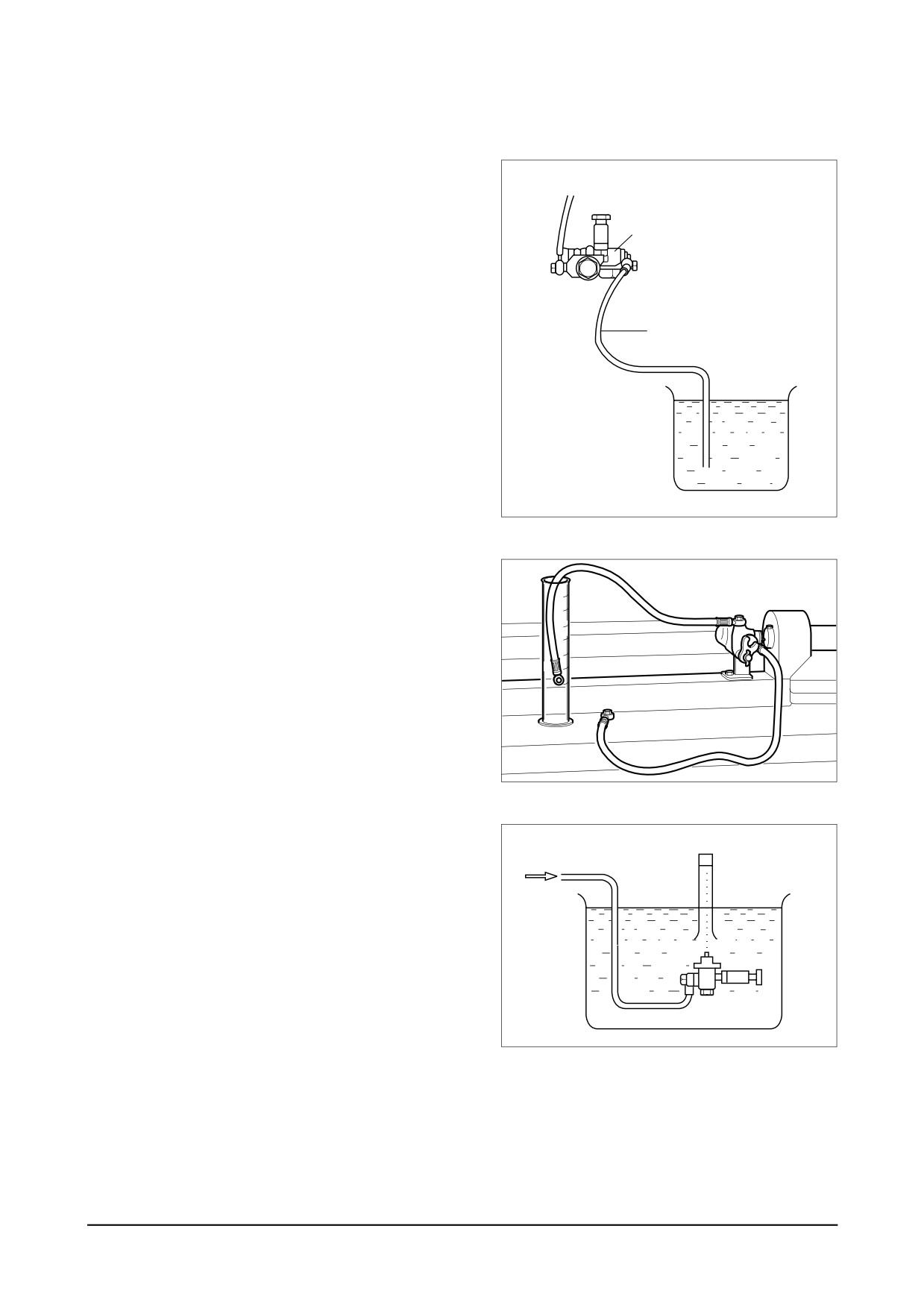
(1)
Suction capacity test
Connect one end of a hose to the
Outlet hose
inlet side of the feed pump and
immerse the other end of it into the
Feed pump
fuel tank as illustrated.
Hold the feed pump in position
about
1 m above the level of fuel in the fuel
Inlet hose
tank.
Operate the tappet at the rate of 100
rpm and check to see if fuel is drawn
in and delivered for 40 seconds or so.
Fuel tank
EQM4022I
(2)
Delivery test
Make a test with the feed pump
mounted on a pump tester as illus-
trated. Operate the pump at the rate
of 1,000 rpm and check to see if the
pump delivery is more than 405 cc /
15 seconds.
EAMC016I
(3) Sealing test
Plug up the delivery port on the feed
Compressed
Mass cylinder
pump and apply compressed air of 2
air 2kg / cm2
kg/cm2 into the inlet side.
Submerge the feed pump in a con-
tainer of diesel fuel and check for air
leak.
Feed pump
EQM4023I
- 144 -
Maintenance of Major Components
10.3.5. Injection nozzle
1) General descriptions
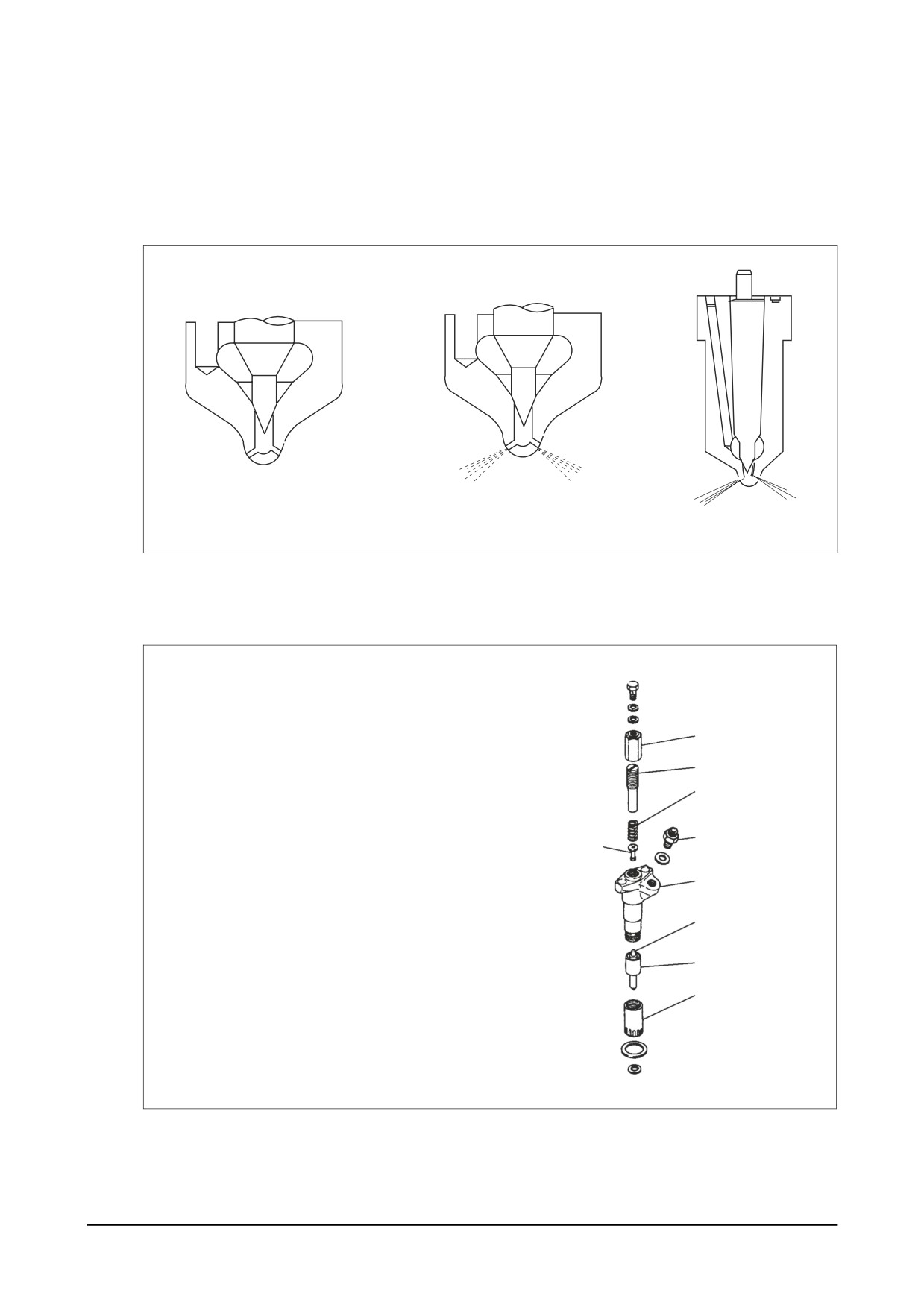
Pressurized fuel delivered from the fuel injection pump is sprayed into the combustion chamber
past the injection nozzle at proper spray pressure and spray angle, then burnt completely to
achieve effective engine performance.
(1) At valve closed
(2) At valve opened
EQM4024I
2) 1-spring type
(1) Disassembly
1
1. Cap nut
2
2. Adjusting screw
3
3. Spring
4. Push rod
5
4
5. Connector
9
6. Retaining nut
7. Needing valve
7
8. Nozzle
9. Nozzle holder
8
6
EI6OM004
Maintenance of Major Components
- 145 -
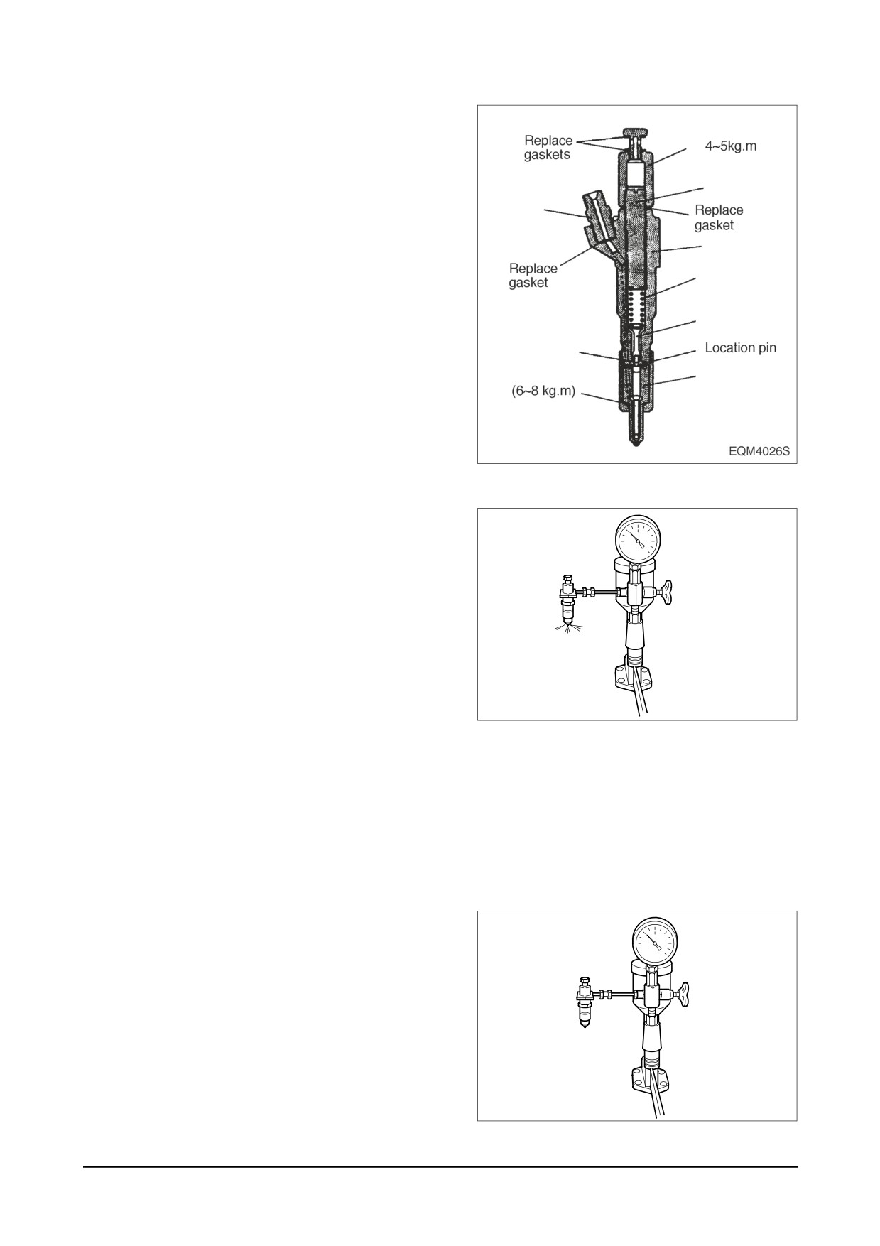
(2) Reassembly
● After removing carbon deposit,
1
submerge the nozzle in diesel oil
and clean it.
2
● Replace all the gaskets with new
5
ones.
9
● Assemble the parts and tighten
them to specified torque.
3
4
7
8
(3)
Adjustment
● Remove the cap nut and assemble
a nozzle to a nozzle tester.
● With the adjusting screw loosened,
operate the nozzle 2 ~ 3 times to
bleed it.
● Operate the nozzle tester lever at
the specified rate.
● Adjust the injection pressure to
EA0M3003
the standard pressure using the
adjusting screw.
● After adjusting the injection
pressure, tighten the cap nut to
specified torque.
● Re-check the injection pressure and
see if the spray pattern is normal.
(4)
Testing
● With the nozzle assembled to a
nozzle tester and pressure of 20
~
21 MPa
(200
~
210 bar)
applied, check the nozzle for fuel
leakage.
EAMC022I
- 146 -
Maintenance of Major Components
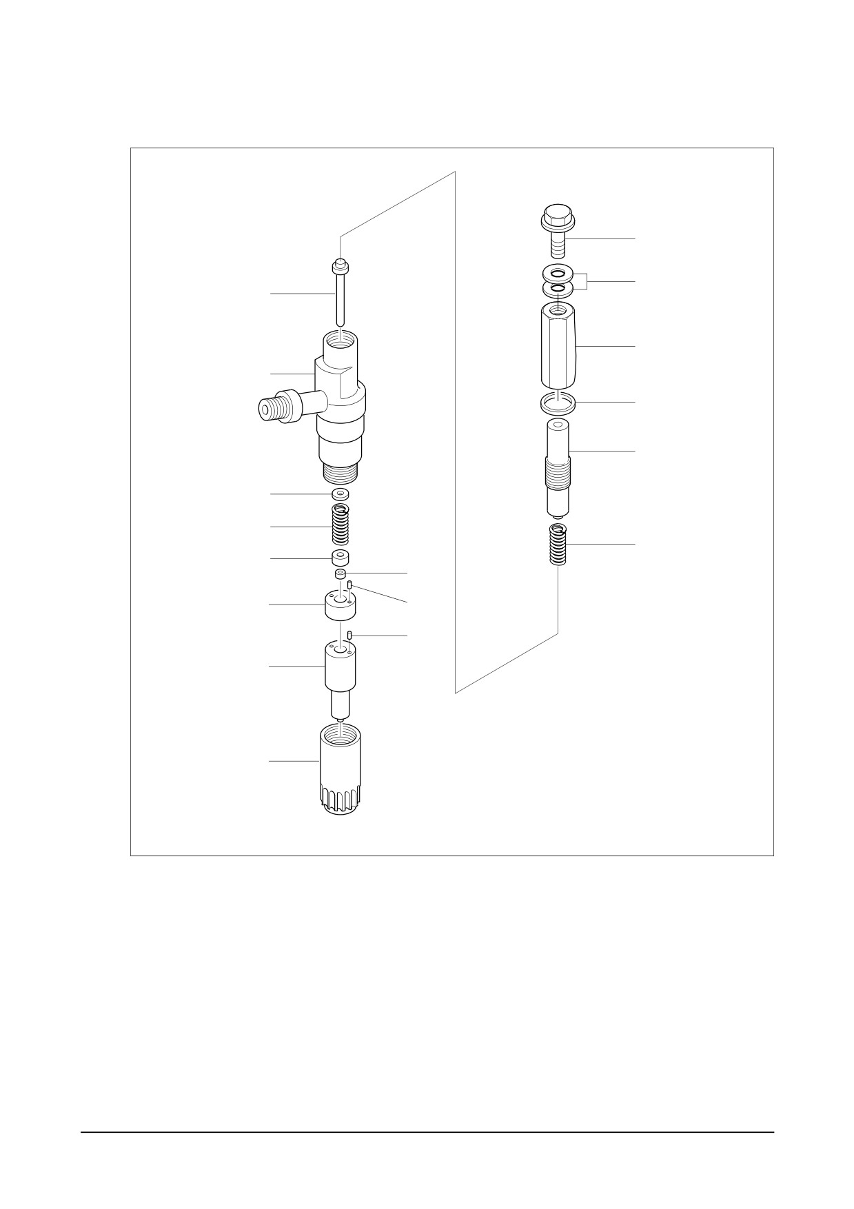
3) 2-spring type
(1) Disassembly
31
30
2
7
1
6
4
10
11
3
12
13
15
14
16
A
17
EQM4029I
1. Nozzle holder body
13. Lift pin
2. Push rod
14. Pin
3. Primary spring
15. Spacer
4. Adjusting screw
16. Pin
6. Gasket
17. Retaining nut
7. Cap nut
30 Gasket
10. Adjusting shim
31 Eye bolt
11. Secondary spring
A. Nozzle
12. Spring Seat
Maintenance of Major Components
- 147 -
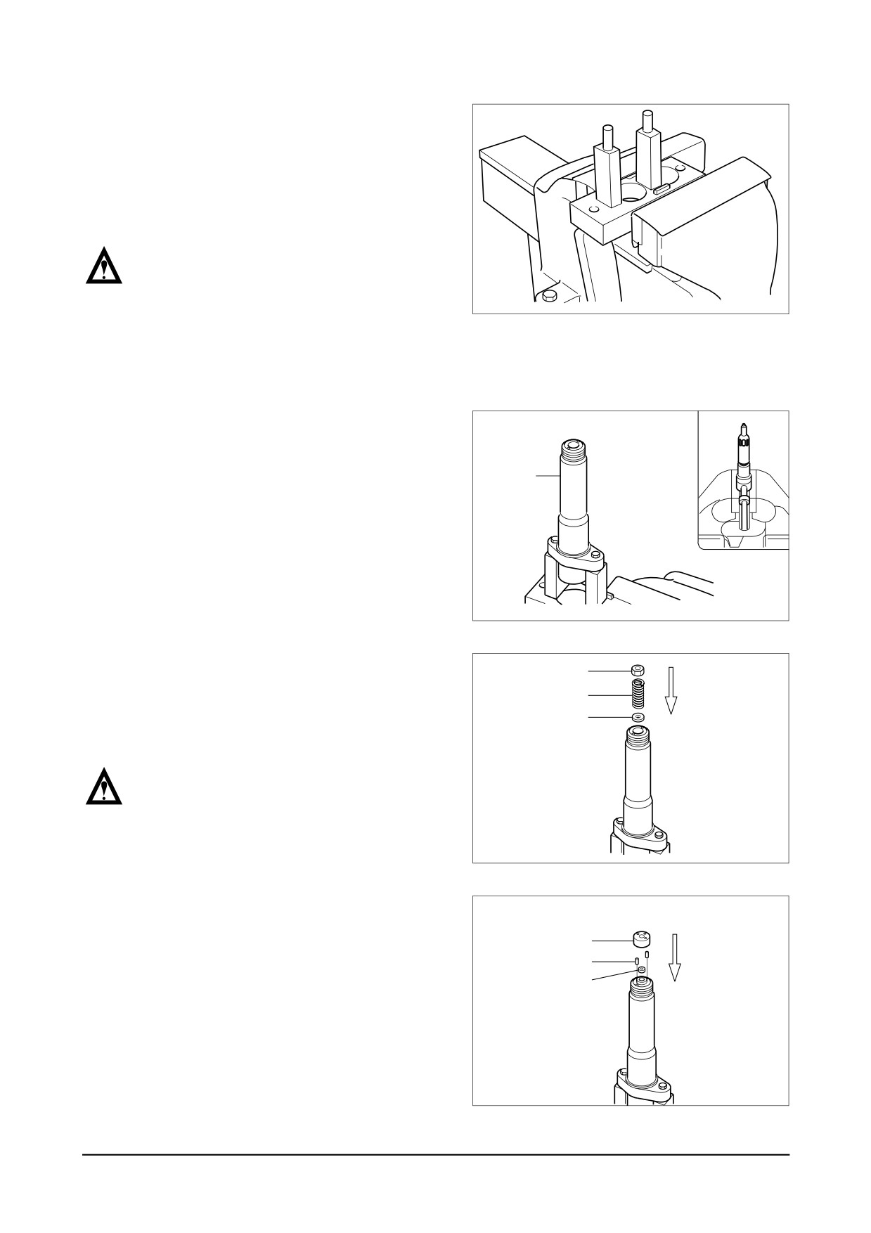
(2) Inspection and adjustment
● Adjusting the primary opening
pressure. Install the plate of plate
assembly (157944-9520) onto a
vise.
NOTE :
Use the plate assembly
(157944-9520) in fixing a nozzle holder
EQM4030I
having a flange. A nozzle holder
without flange should be directly
installed onto a vise.
● With the nut, install the two pins
on the plate.
● Install the nozzle holder body (1)
1
onto the plate with the cap nut
side facing downward.
EQM4031I
● Assemble adjusting shim
(10),
12
secondary spring (11), and spring
11
seat
(12) on the nozzle holder
10
body in the order as described.
NOTE :
The secondary spring is the same one
as the primary spring.
EQM4032I
● Assemble the pin (14), lift piece
(13), and spacer
(15) with the
15
nozzle holder body.
14
13
EQM4033I
- 148 -
Maintenance of Major Components
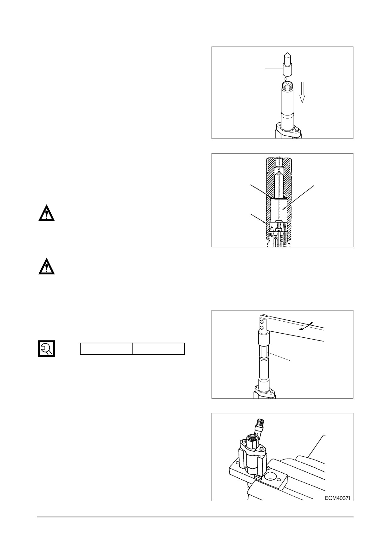
● Install the pin (16) and nozzle (A)
onto the spacer.
A
16
EQM4034I
● After installing the gasket (6:157892-
1500) on the nozzle, use the cap nut
(7:157892-4000 : SW22 mm) to fix
6
1
the nozzle onto the nozzle holder.
NOTE :
7
While tightening the cap nut, keep
checking to see if the lock pin comes
all the way into the nozzle.
EQM4035S
NOTE :
Tighten the retaining nut until it resists
hand tightening, then further tighten it
using a torque wrench.
● Be sure to follow the specified
torque rating when tightening the
adjusting retaining nut.
Torque
6.0 ~ 8.0 kg⋅m
7
EQM4036I
● With the cap nut facing upward,
install the nozzle holder on the
plate.
Maintenance of Major Components
- 149 -
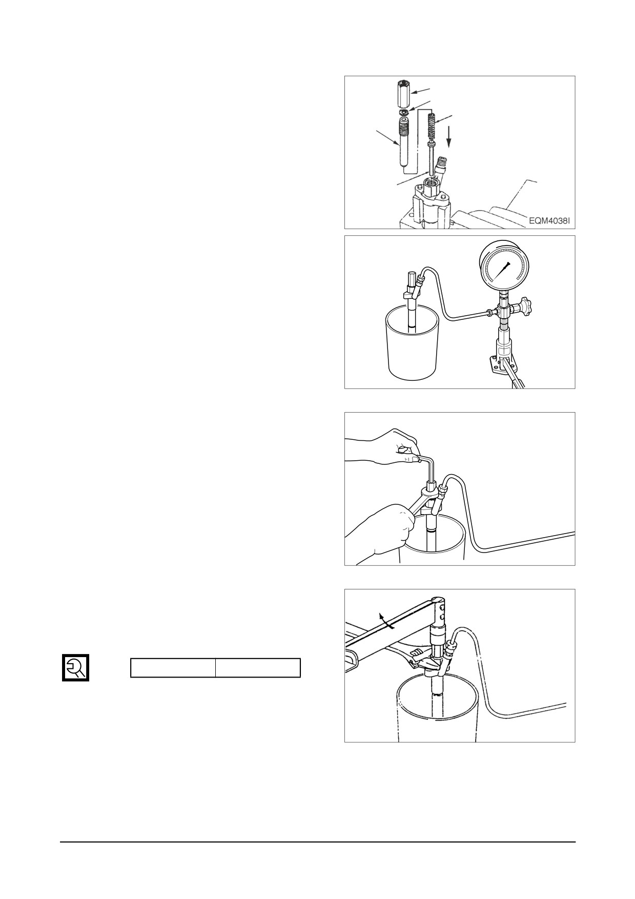
● Assemble the push rod (2), pri-
7
mary spring
(3), and adjusting
6
screw (4) on the nozzle holder in
3
the order described.
4
● Install the gasket (6) and cap nut
(7) onto the adjusting screw(4).
2
● Assemble the nozzle and nozzle
60
holder assembly to the nozzle
40
80
20
tester (105785-1010).
0
100
EQM4039I
● Adjust the primary opening pres-
sure to the specified pressure
using the adjusting screw (4).
EQM4040I
● With a monkey wrench, fix the noz-
zle holder securely and tighten the
cap nut (SW 19mm) to specified
torque.
Torque
3.0 ~ 4.0 kg⋅m
EQM4041I
- 150 -
Maintenance of Major Components
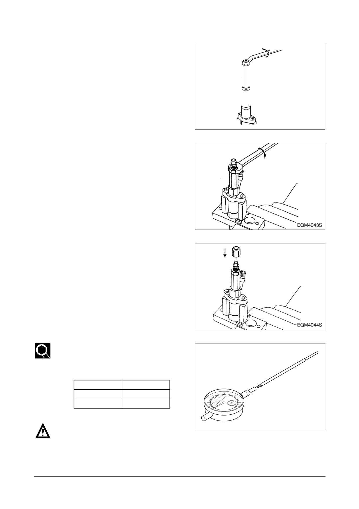
(3) Inspecting the needle valve for full lift
● Install gasket
(026508-1140) and
plug
(157892-1600
: SW12 mm)
onto the adjusting retaining nut
(157892-1400).
EQM4042I
● Install the nozzle holder on the
plate with the cap nut facing
upward.
● Install the holder(157892-4100
:
SW12 mm) into the cap nut.
● Install a nut (157892-1000 : SW
17 mm) on the holder.
● Assemble the pin (157892-4200
or
157892-4300) to the dial
gauge (157954-3800).
(mm)
Part No.
Limit
157892-4200
160
157892-4300
110
NOTE :
EQM4045I
“L” means the length of the pin except
the threaded portion.
Maintenance of Major Components
- 151 -
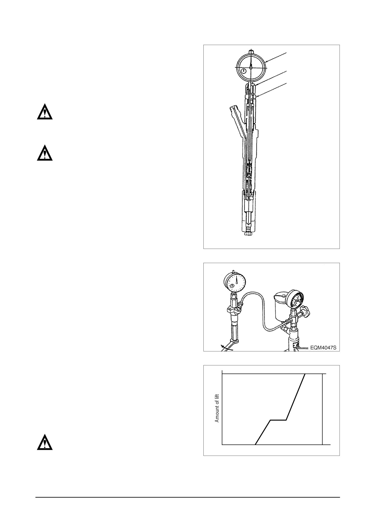
● Install the dial gauge on the
Dial gauge
holder assembly so that the pin is
brought into contact with the
Threaded part
upper end of the push rod, then
Holder
fix the pin with the nut.
NOTE :
Fix the dial gauge so that a stroke of 2
mm or so can be measured.
NOTE :
Overtightening the nut may cause a
sticking of the dial gauge seat.
EQM4046S
● Assemble the nozzle and nozzle
holder assembly to the nozzle
tester and zero the dial gauge.
● Operate the nozzle tester, bleed
the retaining nut, and check for
fuel leakage.
● Operate the nozzle tester and
L
increase the tester pressure up to
350 ~ 450 kgf⋅cm2 in order that
the needle valve can be fully
lifted. Then, record the full lift
value “L”.
NOTE :
0
This testing is to be made in order to
Tester pressure
EQM4048I
check the nozzle seat portion for
unusual wear or whether the nozzle
assembly is a standard item.
- 152 -
Maintenance of Major Components
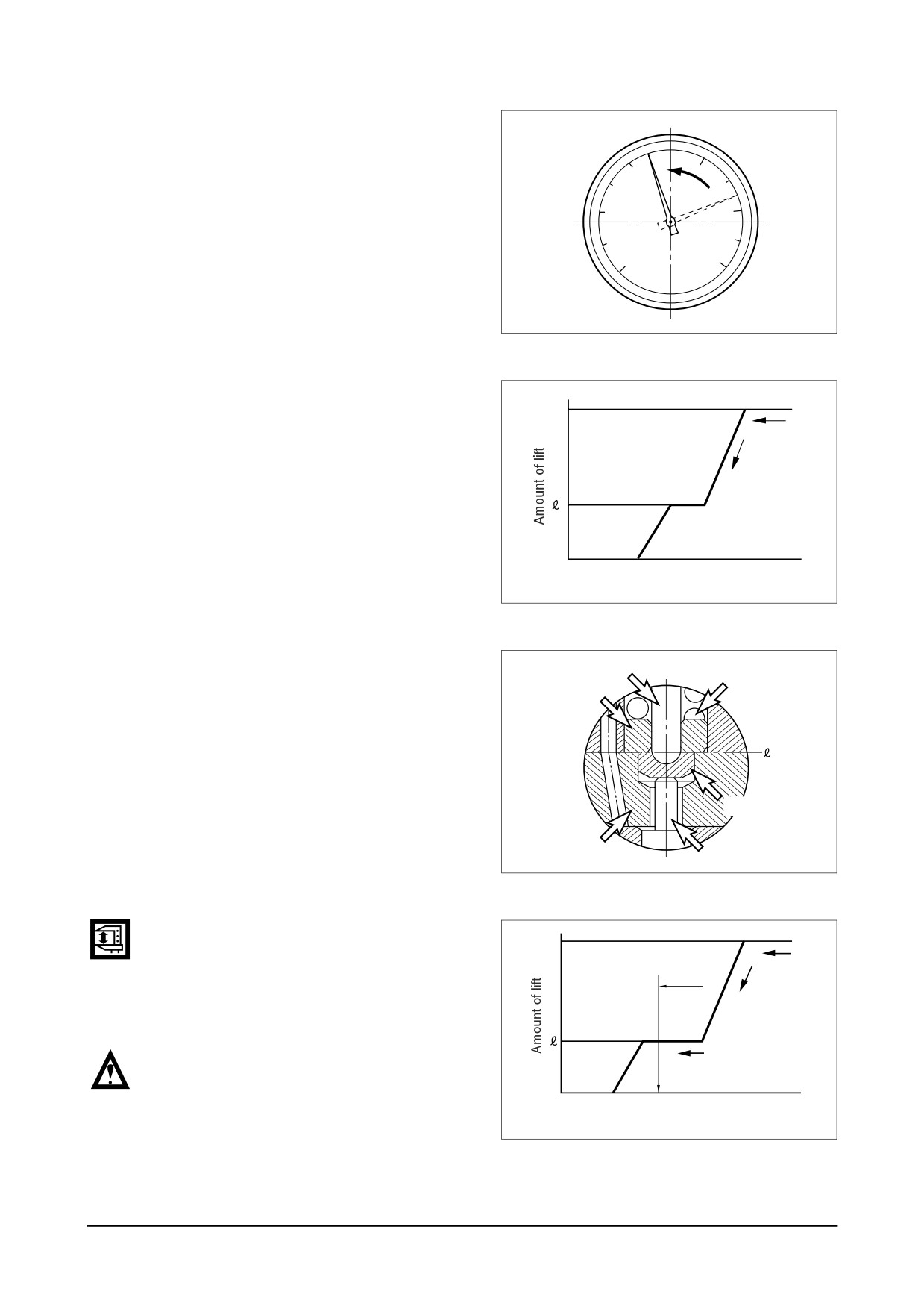
(4) Inspection of pre-lift
● If the nozzle tester handle is
released with the needle valve
200
300
engaged in a full lift condition, the
100
400
tester pressure drops, being accom-
panied by decrease in the needle
valve lift value (indicated value on
500
0
the dial gauge).
kgf /
cm2
EQM4049I
L
0
Tester pressure
EQM4050I
● Take the indicated value on the
Push rod.
Second spring
dial gauge at the point of time
Spring seat
when the secondary spring com-
pletes its operation and the needle
valve puts an end to descent (the
position of needle valve lift value
"ℓ " as shown in the above and
Lift piece
right figures) and check that the
value is within the specified limit.
Spacer
Needle valve
EQM4051I
(5) Measuring point for pre-lift
L
Take the indicated value on the dial
gauge at a point of primary opening
pressure approx. + 10 kgf⋅cm2.
NOTE :
Locate the point of primary opening
0
pressure approx.
+10 kgf⋅cm2 while
Primary opening pressure
Tester pressure
EQM4050I
dropping the pressure.
Maintenance of Major Components
- 153 -
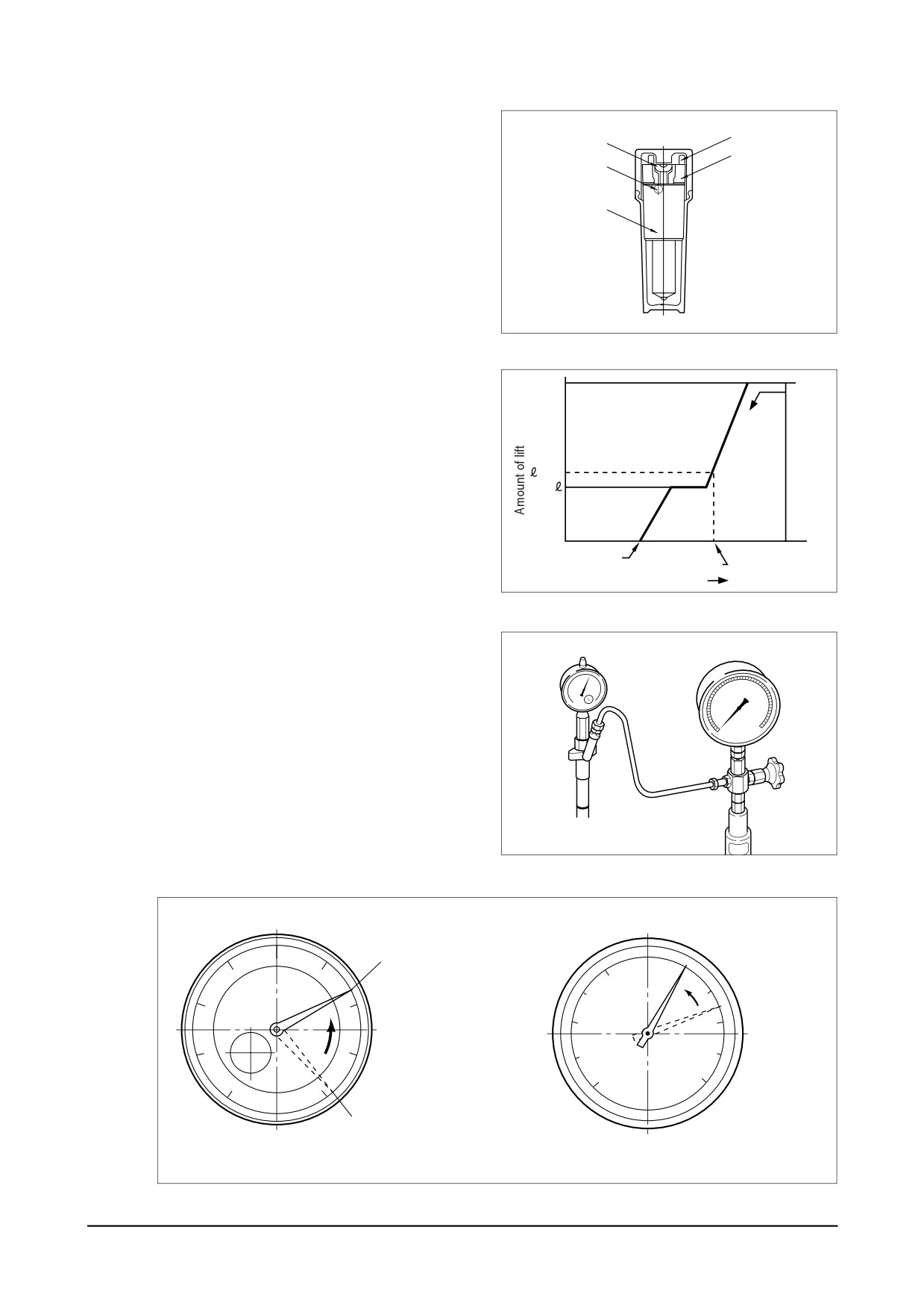
● If the measured pre-lift value devi-
ates from the specified limit,
13
14
15
replace the pin (14, 16), lift piece
16
(13), spacer
(15), and nozzle
assembly (A) with a new “nozzle
A
service kit”.
EQM4053I
(6)
Inspection of secondary opening
L
pressure
● After confirming the pre-lift, operate
the nozzle tester and increase the
internal pressure up to 350 ~ 450
+0.05
kgf⋅cm2 to fully lift the needle valve.
● Release the nozzle tester handle
0
to decrease the tester pressure,
Primary
Secondary
350~450
then take a note of the move-
opening opening pressure
kgf/cm2
Tester pressure
EQM4054I
ments of the dial gauge.
● Take the indicated value on the
pressure gauge at the point of
60
time when the needle of the dial
40
0
80
20
gauge indicates the specified
0
100
needle valve lift value. (In gen-
eral, pre-lift "ℓ "
+
0.05 mm.
Refer to following figure).
EQM4055I
Read the pressure
Lift of needle valve
values of gauge
Ɏ+ 0.05 ɘ
0
90
200
300
10
80
20
100
400
70
30
500
0
60
40
50
Max. lift of needle valve
Dial Gauge
Pressure Gauge
EQM4056I
- 154 -
Maintenance of Major Components
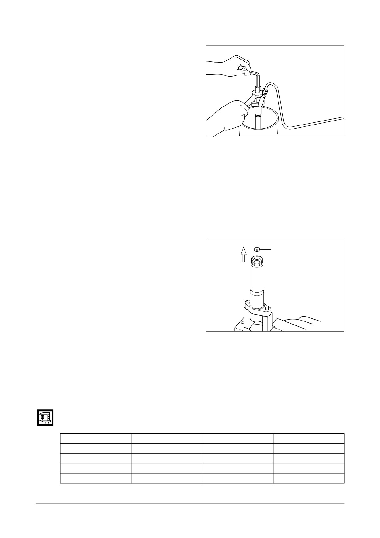
(7)
Adjusting secondary opening pressure
● In the event that the measured
value deviates from the specified
limit, readjust the primary opening
pressure if the amount of deviation
is small. (to the standard range of
the primary opening pressure)
-
If the secondary opening pressure
is lower than the standard value:
EQM4040I
Adjust the primary opening pres-
sure up to the top limit of the stan-
dard vague, and then measure the
secondary opening pressure.
-
If the secondary opening pressure
is higher than the standard value:
In a reverse manner, readjust the
primary opening pressure down to
the bottom limit of the standard
value.
● If the secondary opening pressure
10
still deviates from the specified limit
in spite of the readjusting the pri-
mary opening pressure, take off
the nozzle fixing portion from the
nozzle holder and remove the
adjusting shim (10).
● If the secondary opening pres-
sure is higher than the standard
EQM4058I
value, fit a thinner adjusting shim
than the existing one.
● After replacing the existing adjust-
ing shim, measure the secondary
opening pressure and continue the
adjustment until a value satisfying
the standard value.
Adjusting shim for secondary opening pressure
(Out diameter = ൵ 9.5 , Inner diameter = ൵ 4.5)
Part No.
Thickness (mm)
Part No.
Thickness (mm)
1505380-4900
0.40
1505380-5300
0.56
1505380-5000
0.50
1505380-5400
0.58
1505380-5100
0.52
1505380-5500
0.60
1505380-5200
0.54
1505380-5600
0.70
Maintenance of Major Components
- 155 -
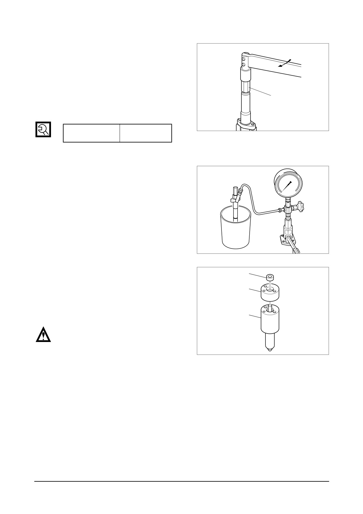
(8) Retaining nut
● Take out the dial gauge, nut,
holder and gasket from the cap
nut (7).
● Remove the adjusting retaining
nut and gasket, and install the
7
original retaining nut
(SW
19
mm).
EQM4036I
Cap nut
m
6.0 ~ 8.0 kg⋅
Tightening torque
(9) Inspection at completion
● Assemble the nozzle holder to a
40
60
nozzle tester and check the pri-
80
20
mary opening pressure, spray
100
0
patterns, oil tightness of seat
portion, and oil leakage from
each part.
EQM4039I
● When replacing the nozzle,
13
replace it with a new
“nozzle
service kit” integrated with a
15
nozzle, lift piece, and spacer as
a complete set.
A
NOTE :
If only a nozzle is replaced, the amount
of pre-lift will deviate from the
EQM4060I
specified value.
- 156 -
Maintenance of Major Components