DOOSAN Generator diesel engine DE12T, P126TI, P126TI-1, P126TI-II, PU126TI. Operation and Maintenance Manual - page 5
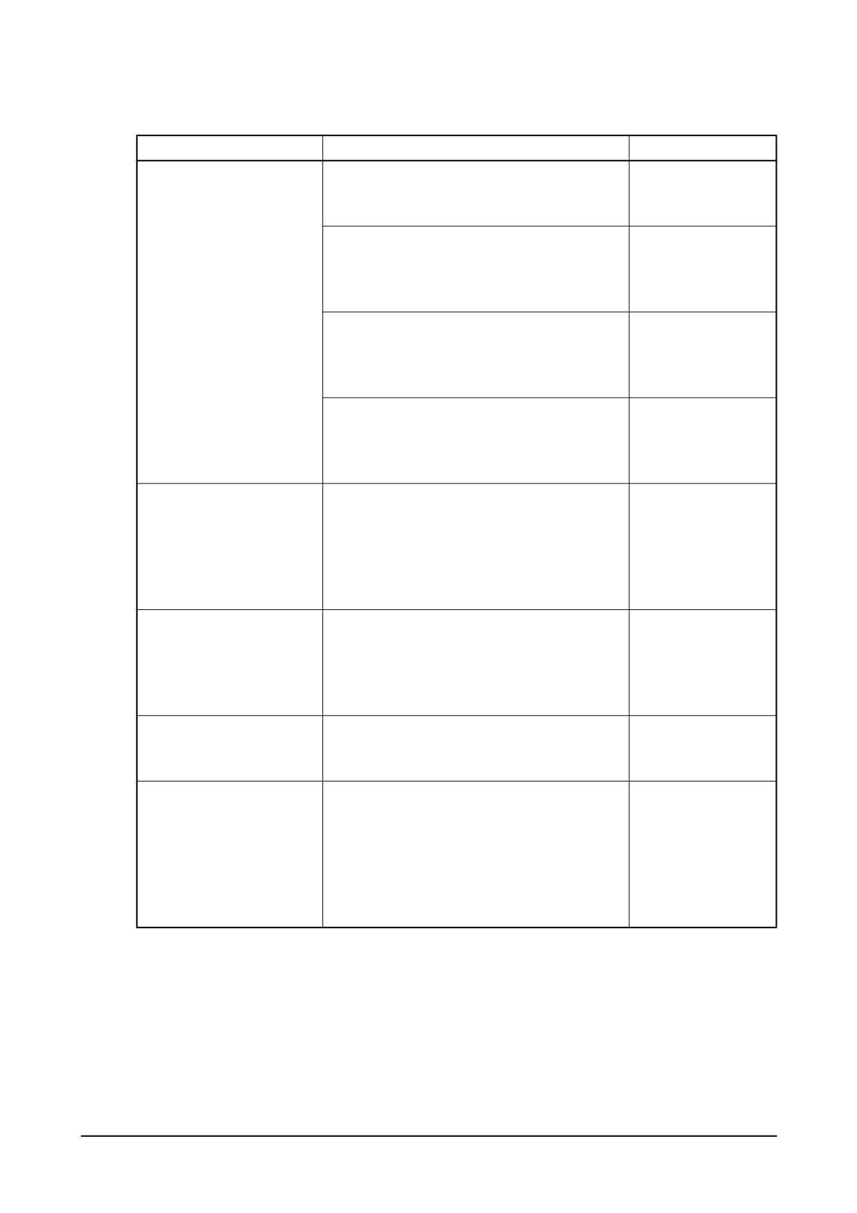
10.3.6. Diagnostics and troubleshooting
Complaints
Possible causes
Corrections
1. Engine won’t start
(1) Fuel pipes clogged or air into pipe line
Correct
1) Fuel not being pumped
(2) Feed pump valve defective
Replace
out from feed pump
(3) Feed pump piston or push rod sticking
Disassemble, correct
2) Fuel not being injected
(1) Fuel filter element restricted
Clean
from injection pump
(2) Air in fuel filter or injection pump
Bleed
(3) Plunger and/or delivery valve sticking or
Disassemble, correct
defective
3) Fuel injection timing
(1) Injection pump not properly installed on
Check, correct
incorrect
pump bracket
(2) Injection pump tappet incorrectly adjusted
Check, correct
(3) Cams on cam shaft worn excessively
Replace
4) Injection nozzles
(1) Needle valves sticking
Correct or replace
inoperative
(2) Fuel leaking past clearance between nozzle
Correct or replace
and needle valve
(3) Injection pressure incorrect
Adjust
2. Engine starts but stalls
(1) Pipe from feed pump to injection pump
Clean
immediately
clogged or filter clogged
(2) Air in fuel
Bleed
(3) Feed pump delivery insufficient
Disassemble, correct
(4) Fuel delivery insufficient due to clogging of
Replace breather
fuel tank air breather
3. Engine lacks power
(1) Plunger worn excessively
Replace
(2) Injection timing incorrect
Adjust
(3) Delivery valves defective
Replace
(4) Nozzle leaks excessively
Correct or replace
(5) Nozzle not working normally
Disassemble, correct
4. Engine knocking
(1) Injection timing too fast
Adjust
(2) Nozzle injection pressure too high
Adjust
(3) Nozzles not working normally
Disassemble, correct
5. Engine knocks seriously
(1) Injection timing incorrect
Adjust
producing excessive
(2) Nozzle injection pressure too low
Adjust
exhaust smoke
(3) Nozzle spring broken
Replace
(4) Nozzles not working normally
Replace
(5) Plungers worn excessively
Adjust
(6) Delivery valves seat defective
Replace
(7) Supply of fuel excessively
Check feed pump
Maintenance of Major Components
- 157 -
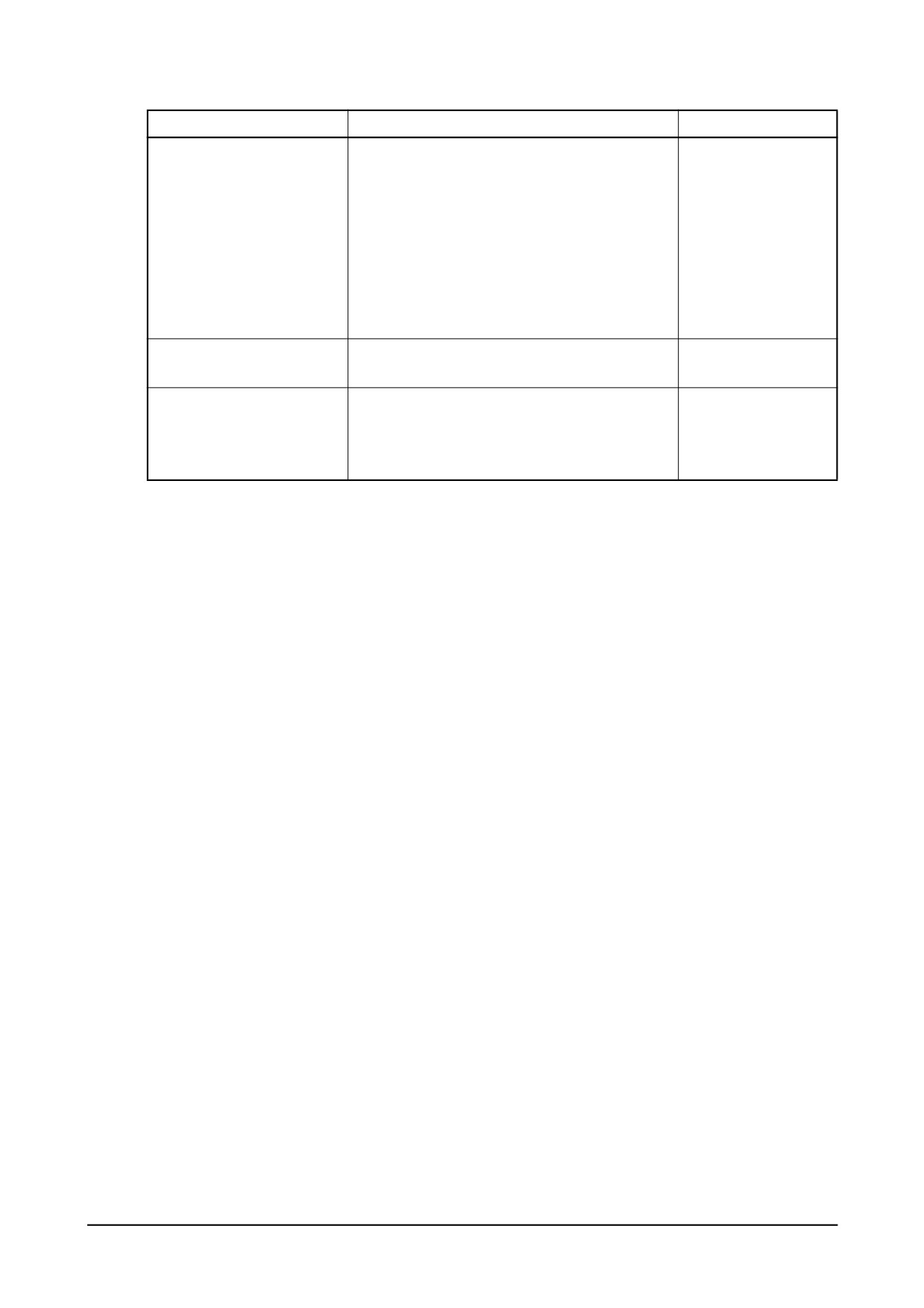
Complaints
Possible causes
Corrections
6. Engine output unstable
(1) Supply of fuel insufficient
Check feed pump
(2) Air in fuel
Bleed
(3) Water in fuel
Replace fuel
(4) Operation of plungers unsmooth
Disassemble, correct
(5) Movement of control rack sluggish
Disassemble, correct
(6) Nozzles defective
Disassemble, correct
(7) Injection starting pressure of each barrel
Adjust
incorrect
(8) Automatic timer defective
Disassemble, correct
7. Engine does not reach
(1) Nozzles not working normally
Disassemble, correct
maximum speed
(2) Governor defective
Disassemble, correct
8. Engine idling unstable
(1) Movement of control rod sluggish
Disassemble, correct
(2) Operation of plungers unsmooth
Disassemble, correct
(3) Control pinions not engaged with control rod
Disassemble, correct
correctly
- 158 -
Maintenance of Major Components
10.4. Turbocharger
10.4.1. Main data and specifications
1) Main data and specifications
P126TI / P126TI-1 /
Specification
DE12T
P126TI-II / PU126TI
Turbocharger Model
Allied Signal T45
Allied Signal TV51
Air pressure at
50 H z: Approx. 1.1 kg/cm2
50 Hz : Approx. 1.5 kg/cm2
compressor outlet
60 Hz : Approx. 1.2 kg/cm2
60 Hz : Approx. 1.8 kg/cm2
At maximum
50 Hz : Approx. 12.5 m3/min
50 Hz : Approx.18.0 m3/min
Air suction volume
output
60 Hz : Approx. 15.0 m3/min
60 Hz : Approx. 23.6 m3/min
50 Hz : Approx 79.270 rpm
50 Hz : Approx. 75910 rpm
Speed of turbine revolution
60 Hz : Approx. 86.850 rpm
60 Hz : Approx. 83150 rpm
Maximum allowable speed
110,072 rpm
105,414 rpm
Max. allowable temperature of exhaust
750°C
750°C
gas at turbine inlet
Lubricating system
External oil supply
External oil supply
Weight
14 kg
14 kg
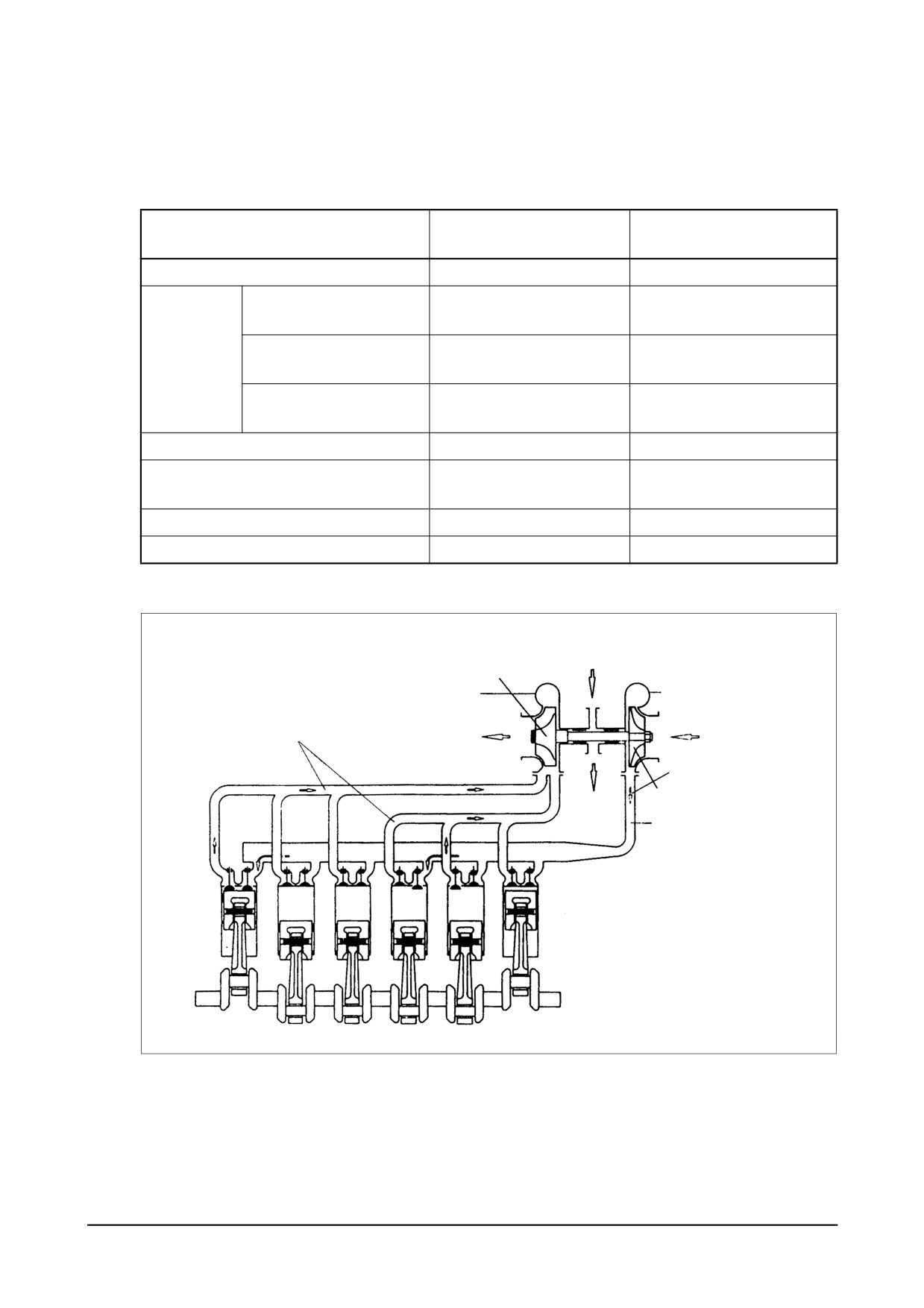
2) Operating principle
Oil inlet
Turbine wheel and
shaft assembly
Compressor
housing
Exhuast pipe
Exhuast gas discharge
Fresh air inlet
Compressed air flow
Compressor wheel
Oil outlet
EA0M8001
The turbocharger is a system designed to make use of the engine exhaust gas energy to charge
high-density air into the cylinders, thereby to increase the engine output.
Maintenance of Major Components
- 159 -
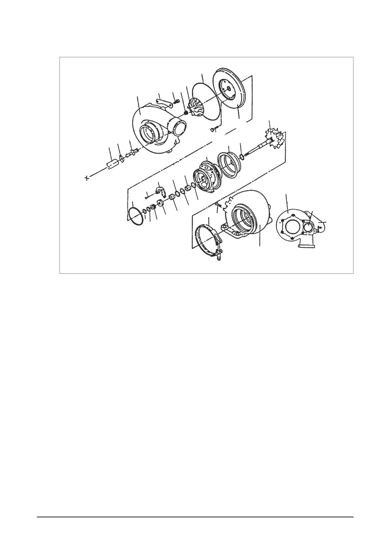
3)
Construction
22
30
29 28
31
8
24
32
25
33
9
10
34
11
15
17
18
1
23
12
2
14
16
7
19
45
20
36
21
1
EA8M4002
1. Turbine housing
14. Retainer ring
24. Rear plate
2. Plug
15. Retainer ring
25. Bolt
5. Crank
16. Bearing
26. Compressor wheel
7. V-band
17. Thrust collar
27. Nut
8. Wheel
18. Screw
28. Bolt
9. Piston ring
19. Thrust bearing
29. Clamp
10. Wheel shroud
20. Thrust space
30. Compressor housing
11. Center housing
21. Piston ring
32. Elbow
12. Retainer ring
22. Seal ring
38. Retainer
13. Bearing
23. Seal ring
45. Bolt
- 160 -
Maintenance of Major Components
10.4.2. General descriptions
The engine output is determined by the fuel delivery volume and engine efficiency.
To burn the supplied fuel completely to change into effective power for the engine, the volume of air
enough to burn the fuel completely should be supplied into the cylinders.
Therefore, the engine output is determined substantially by the cylinder capacity, and a greater vol-
ume of compressed air is charged into cylinders of given capacity, the greater engine output can be
obtained as a greater volume of air charged into the cylinders burns so much more fuel.
As explained, the compressing of air to supply into the cylinders is called “Supercharging” and the
making use of the energy of exhaust gas discharged from the combustion chamber to charge the
compressed air into the cylinders is called “Turbocharging”.
10.4.3. Functions
1)
Turbine
Exhaust gas discharged from the combustion chamber distributes its own energy to the turbine
blades while passing the inside of the turbine housing, with the result that the turbine shaft can get
rotating force. This is the operating principle of ‘turbine’, which is mounted with seal rings and heat
protector to prevent exhaust gas from affecting the bearings adversely.
2)
Compressor
The compressor, which is connected to the turbine over the one and same shaft to form a rotating
body, takes in and compresses ambient air with rotating force transmitted from the turbine shaft.
Then, the compressed air is delivered to the intake stake. This is the operating principle of the com-
pressor.
3)
Bearings
(1) Thrust bearing
The turbine wheel creates thrust force. Therefore, exercise care so that the shaft is not devi-
ated from its the original position due to this thrust.
(2) Journal bearing
This journal bearing of floating type forms a dual oil film on both the inside and outside of the
bearing so that the bearing can rotate independently. As the dual oil film plays a role as a
damper, the sliding speed of the bearing surface becomes lower than the rotating speed of the
shaft, resulting in assurance of stability in its movement.
(3) Sealing-Compressor shaft
The compressor is of a dual construction type composed of seal plate and seal ring to prevent
the leak of compressed air or lubricating oil.
Maintenance of Major Components
- 161 -

10.4.4. Precautions for operation
1) Precautions for operation of engine
The following precautions should be observed when starting, operating, or stopping the engine:
Operations
Precautions
Reasons
When
1)
Check oil level
starting
2)
Crank the engine with starter to check the
2) Abrupt starting of the engine causes
the engine
increase in oil pressure(until the needle of
the engine to rotate with oil not being
pressure gauge starts to move or pressure
distributed not only to each part but
indicator lamp is actuated) before starting
also to the turbocharger, resulting in
the engine.
abnormal wear or seizure on the
bearing due to insufficient supply of
oil.
3) When having replaced oil, oil filter element,
3) In the case of the engine stopped for
or lubricating parts, or when having stopped
extended time or in a cold place, oil
the engine for extended period of time, or in
fluidity within the pipes can be deteri-
a cold place, loosen the oil pipe connections
orated.
and operate the starter motor until oil is dis-
charged. After completing the operation, be
sure to retighten the oil pipe connections
portion before starting the engine.
Immediately
1)
Run the engine at idle for 5 minutes after
1)
Applying load abruptly If load is
after
starting off.
abruptly applied with the engine and
starting
turbocharger rotating unsmoothly,
such parts that a sufficient amount of
oil has not reached can be seized up.
2) Check each part for leakage of oil, gas, and
2)
Leakage of oil, gas, and air (espe-
air, and take proper measure.
cially, oil leak) causes drop in oil pres-
sure and loss of oil. resulting in
seizure of the bearing.
During
Check the followings:
1)
Excessively low oil pressure causes
operation
1) Oil pressure
unusual wear or seizure of the bear-
At idle: 0.8 kg/cm2 or more
ing. Too high pressure causes oil
At full load: 3.0 ~ 4.8 kg/cm2
leakage.
2) If unusual sound or vibration is heard or felt,
2)
The engine is operated continuously
reduce engine revolutions slowly and locate
with unusual sound or vibration not
the cause.
corrected, it can be damaged beyond
repair.
When
1) Run the engine at idle for 5 minutes before
1)
If the engine is put to a stop after
stopping
stopping.
being operated at high load, heat
the engine
from the red-hot turbine blades is
transmitted to the bearing portion and
burns oil to cause seizure of the bear-
ing metal and rotating shaft.
- 162 -
Maintenance of Major Components
10.4.5. Walk-around check and servicing
As the condition of turbocharger depends greatly on how well the engine is serviced, it is very impor-
tant to maintain the engine in accordance with the specified maintenance procedure.
1)
Intake system
Pay particular attention to the air cleaner when servicing the intake system.
In the case of wet-type air cleaner, if the level of oil surface is lower than specified, cleaning effect
is poor; if too high, the cleaner draws in oil to foul the case.
Especially, if the rotor is fouled, the sophisticatedly-tuned balance is broken to create vibration and
to cause seizure and unusual wear to the bearing.
Therefore, it is very important to use a good quality air cleaner all the time.
In the case of dry-type air cleaner, it is essential to clean it to reduce intake resistance as much as
possible.
2)
Exhaust system
Pay particular attention to prevent gas leaks and seizure when servicing the exhaust system
because leakage of exhaust gas from discharge pipes, turbocharger fixing portions, etc. lowers
charging effect.
As such components as turbine chamber that becomes red-hot during operation use heat resisting
steel nuts, do not interchange these nuts with ordinary steel nuts. In addition, apply anti-seizure
coating to fixing nuts on the portions as designated.
3)
Fuel system
If the full load stopper regulating the maximum injection volume and the maximum speed stopper
regulating the maximum speed in the fuel injection pump are adjusted without using a pump tester,
the turbocharger rotates at excessively rapid speed and may suffer damage.
Besides of it, if spray pattern from the fuel injection nozzles is bad or the injection timing is incor-
rect, temperature of exhaust gas rises up to affect the turbocharger adversely. To avoid such trou-
ble, be sure to make a nozzle test.
4)
Lubricating system
Pay particular attention to oil quality and oil filter change intervals when servicing the lubricating
system. Deteriorated engine oil affects adversely not only the engine but torso the turbocharger.
Suggested engine oils for the turbocharger-mounted engine are as follows:
● SAE 15W30
● API grade CD or CE
Maintenance of Major Components
- 163 -

10.4.6. Periodical checking and servicing
Make it a rule to check the turbocharger assembly for condition and contamination periodically.
1) Guide for checking the rotor for rotating condition
The inspection of the rotor assembly for rotating condition should be performed by the degree of
unusual sound. If a sound detecting bar is used, install its tip on the turbocharger housing and
increase the engine revolutions slowly. If a high-pitch sound is heard continuously, it means that
the rotor assembly is not normal. In this case, as the metal bearing and rotor are likely to be in
abnormal conditions, the turbocharger should be replaced or repaired.
2) Guide for checking rotor end play
Disassemble the turbocharger from the engine, then check the rotor axial play and radial play.
When disassembling the turbocharger, be sure to plug the oil inlet and outlet ports with taps, etc.
(1) Rotor axial play
Turbine wheel chamber
Magnetic vise
(2) Rotor radial play
Move the turbine
shaft in axial
direction
Dial gauge
Standard
: 0.117 ~ 0.20mm
Limit of werar : 0.24mm
EA8M4003
Dial gauge
Magnetic vise
Oil outlet
Radial play
Move the turbine shaft
Standard
: 0.075 ~ 0.11mm
in both direction
Limit of wear : 0.12mm
simultaneousty
Oil inlet
EA8M4004
(3) If the measured axial and radial plays are beyond the limit of wear, replace or repair the turbo-
charger.
- 164 -
Maintenance of Major Components
3)
Guide for disassembling/cleaning and checking the turbocharger
First, disassemble the turbocharger from the engine and clean/check it with the oil inlet and outlet
plugged with tape and so on.
4)
Precautions for reassembling the tarbocharger onto the engine
For reassembly of the turbocharger or handling it after reassembly operation, be sure to observe
the following precautions:
Especially, exercise extreme care to prevent foreign matters from entering the inside of the turbo-
charger.
(1) Lubricating system
● Before reassembling the turbocharger onto the engine, inject new oil in the oil inlet port and
lubricate the journal and thrust bearings by rotating them with hand .
● Clean not only the pipes installed between the engine and oil inlet port but also the oil outlet
pipe and check them for damage or foreign matters.
● Assemble each joint on oil pipes securely to prevent oil leaks.
(2) Intake system
● Check the inside of the intake system for foreign matters.
● Assemble each joint on the intake duct and air cleaner securely to prevent air leaks.
(3) Exhaust system
● Check the inside of the exhaust system for foreign matters.
● Be sure to use heat resisting steel bolts and nuts. Do not interchange them with ordinary
steel bolts and nuts when performing reassembly operation. Apply anti-seizure coating to
the bolts and nuts.
● Assemble each joint on the exhaust pipes securely to prevent gas leaks
Maintenance of Major Components
- 165 -

10.4.7. Diagnostics and troubleshooting
Complaints
Possible causes
Corrections
1) Air cleaner element clogged
Replace or clean
2) Restrictions in air duct
Check and correct
3) Leakage at intake manifold
Check and correct
1. Excessive
4) Turbocharger seized up and not rotating
Disassemble/repair or replace
black smoke
5) Turbine blades and compressor blades coming
Disassemble/repair or replace
in contact with each other or damaged
6) Exhaust piping deformed or clogged
Check and correct
1) Oil leak into turbine and compressor
Disassemble/repair or replace
2. Excessive
2) Worn or damaged seal ring due to excessive
Disassemble/repair or replace
white smoke
wear of bearing
1) Gas leak at each part of exhaust system
Check and correct
3. Low engine
2) Air cleaner element restricted
Replace or clean
output
3) Turbocharger fouled or damaged
Disassemble/repair or replace
4) Leakage at discharge port on compressor side
Check and correct
1) Rotor assembly coming in contact
Disassemble/Repair or replace
4. Unusual sound
2) Unbalanced rotation of rotor
Disassemble/Repair or replace
contact
3) Seized up
Disassemble/Repair or replace
4) Each joint loosened
Check and correct
- 166 -
Maintenance of Major Components
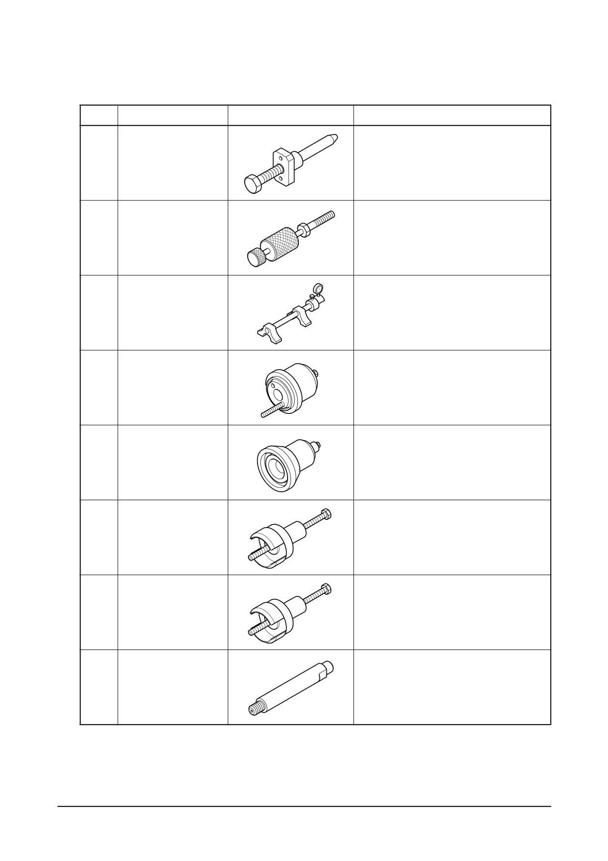
11. Special Tool List
No
Part no.
Figure
Tool name
1
DPN-5337
Nozzle tube insert ass’y
2
EF.123-082
Nozzle tube extractor
3
EF.123-015
Injection pump setting ass’y
4
EF.123-173
Oil seal(NOK) insert ass’y (FR)
5
EF.123-194A
Oil seal(NOK) insert ass’y (RR)
6
EF.123-317A
Oil seal(NOK)puller ass’y (FR)
7
EF.123-316A
Oil seal(NOK) puller ass’y (RR)
8
EF.123-347
Cylinder pressure tester adapter
Special Tool List
-
167 -
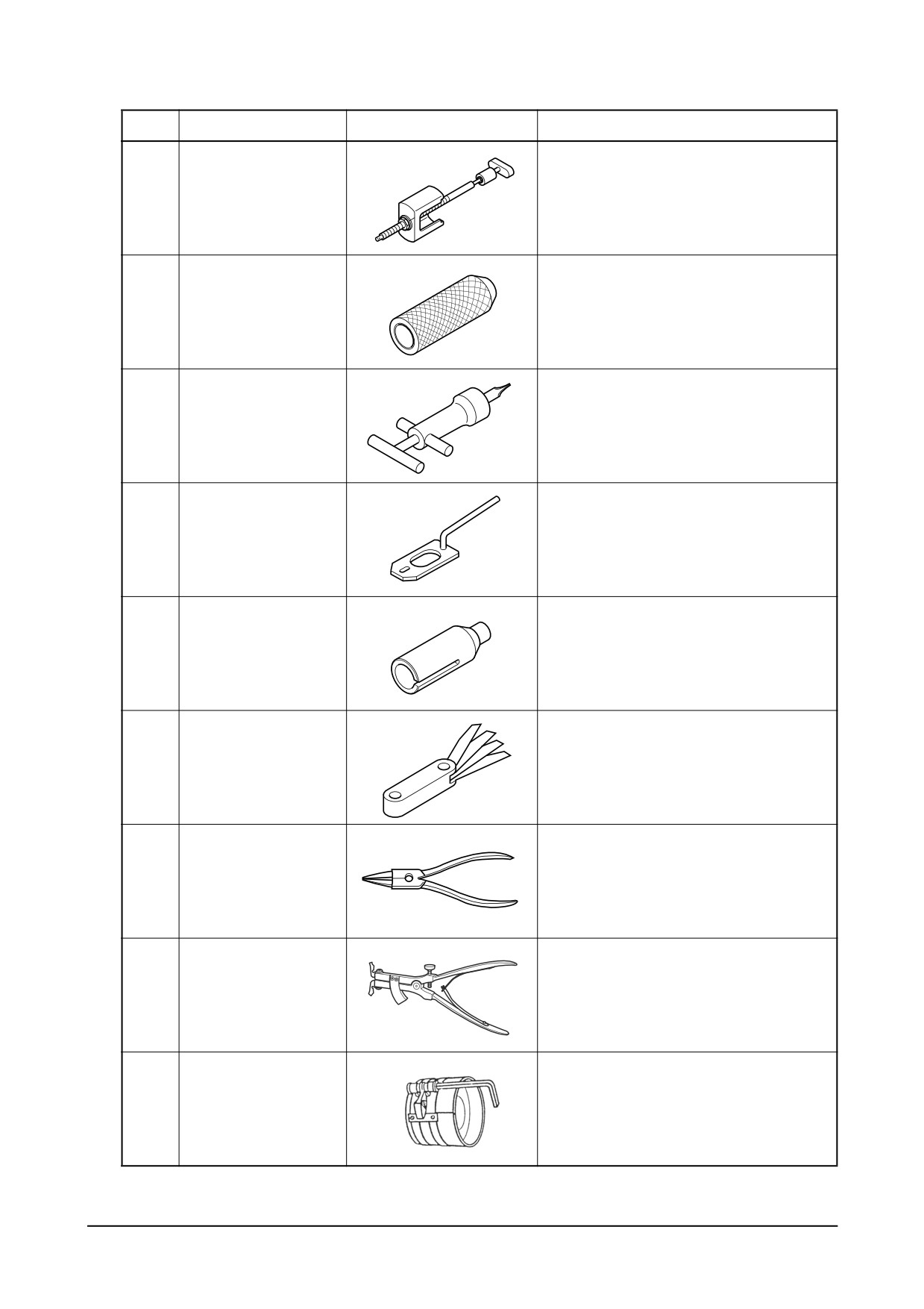
No
Part no.
Figure
Tool name
9
EF.123-087
Cylinder liner puller ass’y
10
EF.123-066
Valve stem seal punch3
11
EU.2-0131
Valve clearance adjust ass’y
12
EF.123.-065
Valve spring press
13
EU.2-0647
Crankshaft gear punch
14
60.99901-0027
Feeler gauge
15
T7610001E
Snap ring plier
16
T7621010E
Piston ring plier
17
EF.120-208
Piston Ring Compressor
-
168 -
Special Tool List
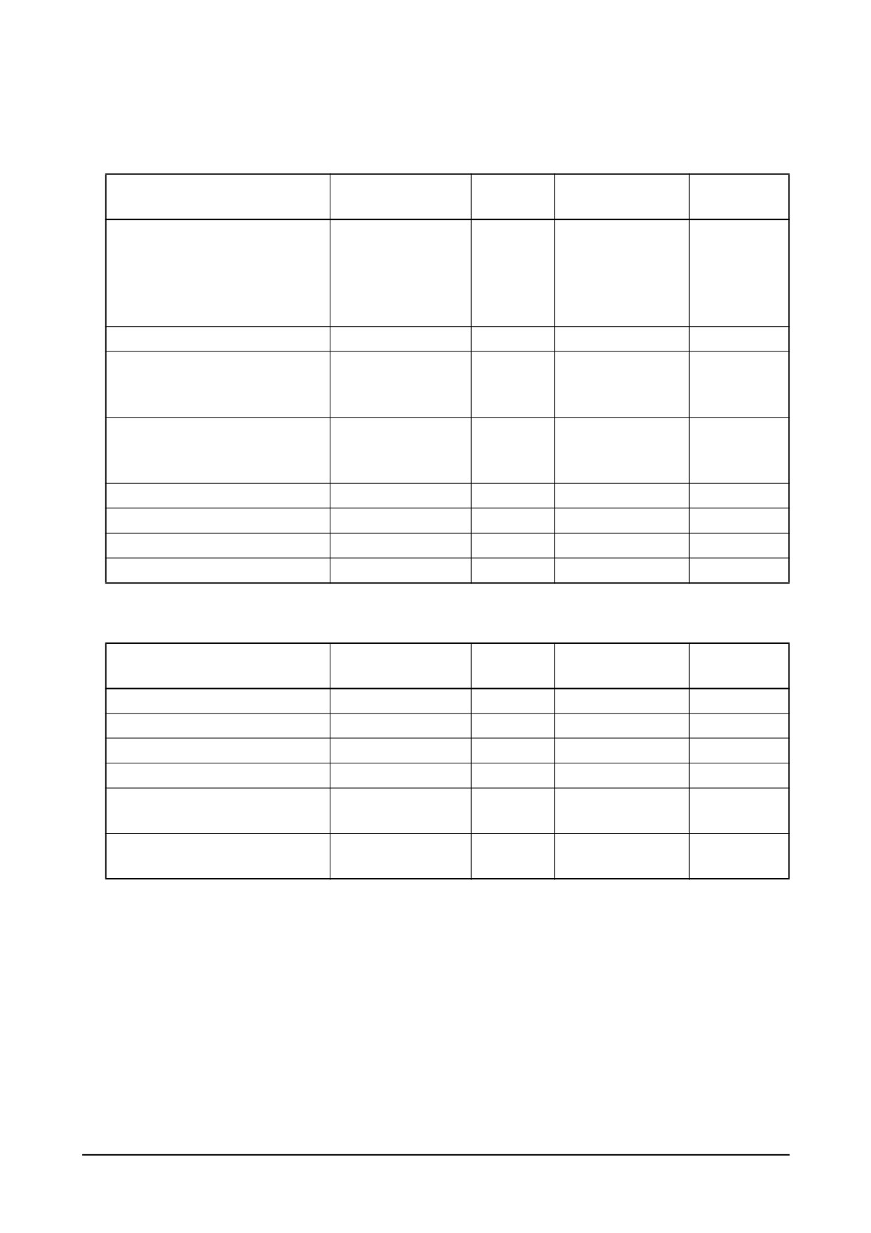
Appendix
● Tightening torque for major parts
Screw
Strength
Major Parts
Tightening Torque
Remarks
(Diameter x pitch)
(grade)
1st : 6 kgm
2nd : 90°
Cylinder head bolt
M14 x 1.5
10.9T
3rd: 90°
Dodecagon
Finished : 90°
(angle torque)
Cylinder head cover bolt
M8
8.8T
1.2 kgm
1st : 15 kgm
Connecting rod bearing cap bolt
M16 x 1.5
12.9T
2nd : 22 kgm
3rd : 30 kgm
1st : 15 kgm
Crankshaft main bearing cap bolt
M16 x 1.5
12.9T
2nd : 25 kgm
3rd : 30 kgm
Balance weight fixing bolt
M14 x 1.5
10.9T
14.0 kgm
Split type
Flywheel fixing bolt
M14 x 1.5
10.9T
18.0 kgm
Crankshaft pulley fixing bolt
M12 x 1.5
12.9T
13.4 kgm
Oil spray nozzle
M6
8.8T
1.0 kgm
● Tightening torque for injection pump system
Screw
Strength
Major Parts
Tightening Torque
Remarks
(Diameter x pitch)
(grade)
Injection nozzle holder nut
M6
8.8T
1.0 kgm
Injection pump bracket
M10
8.8T
4.4 kgm
Injection pump coupling bolt
M10
-
6.0 kgm
Injection pump driving gear nut
M24 x 1.5
8.8T
25.0 kgm
High pressure injection pipe fixing
M14 x 1.5
8.8T
3.0 kgm
cap nut
Injection pump delivery valve
-
-
13 ~ 14 kgm
holder
Appendix
-
169 -
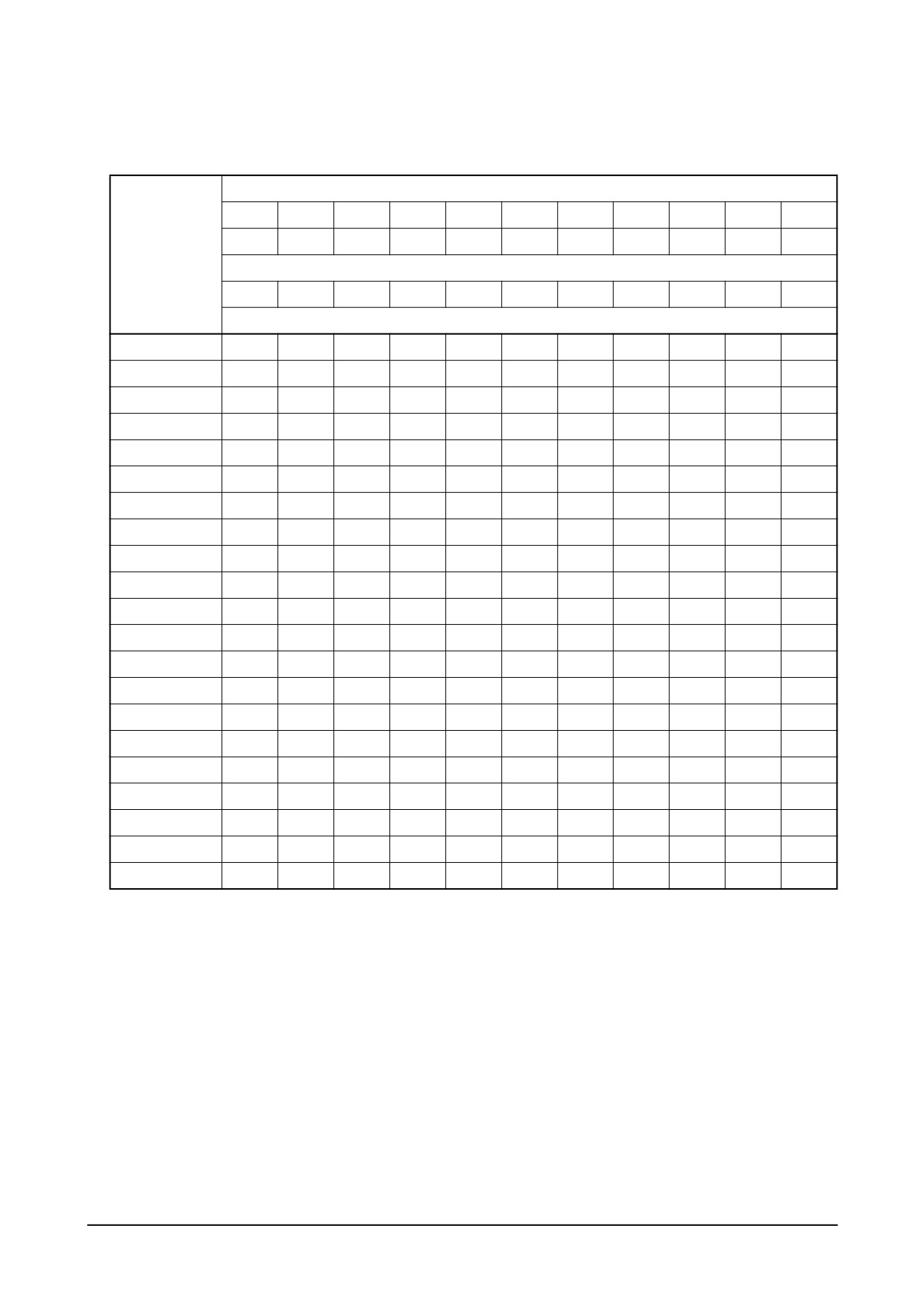
● Standard bolt tightening torque table
Refer to the following table for bolts other than described above.
Degree of strength
3.6
4.6
4.8
5.6
5.8
6.6
6.8
6.9
8.8
10.9
12.9
(4A)
(4D)
(4S)
(5D)
(5S)
(6D)
(6S)
(6G)
(8G)
(10K)
(12K)
Limit value for elasticity (kg/mm2)
20
24
32
30
40
36
49
54
64
90
108
Tightening torque (kgm)
M5
0.15
0.16
0.25
0.22
0.31
0.28
0.43
0.48
0.5
0.75
0.9
M6
0.28
0.30
0.45
0.4
0.55
0.47
0.77
0.85
0.9
1.25
0.5
M7
0.43
0.46
0.7
0.63
0.83
0.78
1.2
1.3
1.4
1.95
2.35
M8
0.7
0.75
1.1
1
1.4
1.25
1.9
2.1
2.2
3.1
3.8
M8 x 1
0.73
0.8
1.2
1.1
1.5
1.34
2.1
2.3
2.4
3.35
4.1
M10
1.35
1.4
2.2
1.9
2.7
2.35
3.7
4.2
4.4
6.2
7.4
M10 x 1
1.5
1.6
2.5
2.1
3.1
2.8
4.3
4.9
5
7
8.4
M12
2.4
2.5
3.7
3.3
4.7
4.2
6.3
7.2
7.5
10.5
12.5
M12 x 1.5
2.55
2.7
4
3.5
5
4.6
6.8
7.7
8
11.2
13.4
M14
3.7
3.9
6
5.2
7.5
7
10
11.5
12
17
20
M14 x 1.5
4.1
4.3
6.6
5.7
8.3
7.5
11.1
12.5
13
18.5
22
M16
5.6
6
9
8
11.5
10.5
17.9
18.5
18
26
31
M16 x 1.5
6.2
6.5
9.7
8.6
12.5
11.3
17
19.5
20
28
33
M18
7.8
8.3
12.5
11
16
14.5
21
24.2
25
36
43
M18 x 1.5
9.1
9.5
14.5
12.5
18.5
16.7
24.5
27.5
28
41
49
M20
11.5
12
18
16
22
19
31.5
35
36
51
60
M20 x 1.5
12.8
13.5
20.5
18
25
22.5
35
39.5
41
58
68
M22
15.5
16
24.5
21
30
26
42
46
49
67
75
M22 x 1.5
17
18.5
28
24
34
29
47
52
56
75
85
M24
20.5
21.5
33
27
40
34
55
58
63
82
92
M24 x 1.5
23
25
37
31
45
38
61
67
74
93
103
Others :
1. The above torque rating have been determined to 70% or so of the limit value for bolt elasticity.
2. Tension is calculated by multiplying tensile strength by cross section of thread.
3. Special screws should be tightened to 85% or so of the standard value.
For example, a screw coated with MoS2 should be tightened to 60% or so of the standard value.
-
170 -
Appendix
● Maintenance specification table
Unit : mm
Stand value
Limit
Group
Part
Inspection item
Correction
Remark
for assembly
for use
Measure unworn
Inside diameter of
Ø123 ~
Ø123.223
Replace liner
portion beneath the
cylinder liner for wear
Ø123.023
rim of upper side
Cylinder
Projected portion of liner
0.03 ~ 0.08
-
block &
The upper surface of
Correct with a
Per distortion length
liner
0.05 / 200
-
cylinder block for distortion
surface grinder
for
200 mm
Hydraulic test for 1
4
-
minute
(kg/cm2)
Engine
In case of new valve
body
Intake
0 ~ 0.3
0.55
and seat
Valve seat
depression
Cylinder
Exhaust
0 ~ 0.3
0.55
head &
valve
Replace
Height
114.95 ~ 115
113.9
cylinder head
Hydraulic test for 1
Water temperature
4
-
Replace if leaky
minute
(kg/cm2)
70°C
18mm
Ø122.870±0.007
-
Piston
88mm
Ø122.750±0.009
-
diameter
124mm
Ø122.450±0.010
-
Clearance between
0.109 ~ 0.166
-
piston and liner
Top ring
3.5
-
Replace piston if
Width of
Major
groove width is
piston ring
2nd ring
3.060 ~ 3.080
-
moving
Piston
beyond specified
grooves
parts
value
Oil ring
4.040 ~ 4.060
-
Piston projection from
Measure unworn
cylinder block upper
0 ~ 0.12
-
portion beneath the
surface
rim of upper side
Permissible weight
difference of each
±15 g
Max. 96 g
Replace piston
piston
Appendix
-
171 -
Unit : mm
Stand value
Limit
Group
Part
Inspection item
Correction
Remark
for assembly
for use
Top ring
0.30 ~ 0.45
1.5
Standard gauge
Piston ring
2nd ring
1.0 ~ 1.2
2.0
inside diameter :
gap
Ø123
Oil ring
0.30 ~ 0.50
1.5
Top ring
0.105 ~ 0.155
-
Piston
Piston ring
Limit for use if for
ring
Replace ring or
groove
2nd ring
0.07 ~ 0.102
0.15
standard
piston
clearance
clearance
Oil ring
0.05 ~ 0.085
0.15
Install ring
Direction of ring gap
-
-
by 120°
Axial run-out of journal and
Correct
In horizontal and
0.05
0.1
pin
with a grinder
vertical directions
Outside diameter of
Ø95.966 ~
Replace
Ø95
Ø96 g6
Major
journal
Ø95.988
crankshaft
moving
Ø82.966 ~
Replace
parts
Outside diameter of pin
Ø82
Ø83 g6
Ø82.988
crankshaft
Out of round of journal & pin
0.008
0.025
Permissible radial run out of
0.01
0.03
journal & pin
Crank
Permissible taper of
shaft
0.01
0.03
journal & pin
Clearance between
Measure in the
0.072 ~ 0.142
0.25
Replace bearing
crankshaft and bearing
position of crown
Replace
End play of crankshaft
0.15 ~ 0.325
0.5
thrust bearing
Adjust by a press
No.4 bearing
Run-out of crankshaft
0.05
0.1 or less
if bent
(holding no. 1 & 7)
Check dynamic
Measure at
Balance of crankshaft
60
60 or less
balance
400 rpm
-
172 -
Appendix
Unit : mm
Stand value
Limit
Group
Part
Inspection item
Correction
Remark
for assembly
for use
Tightening torque of
No foreign matters
journal bearing cap bolt
30
-
Apply oil to bolt
on bearing cap
(kgm)
installing surface
Measure by
Crank
tightening metal cap
shaft
Journal bearing crush
0.15 ~ 0.25
-
& then loosening
one stud bolt
Replace oil seal if
Replace with new
Oil seal for wear
-
-
oil leaking
one, use shim
Clearance between con-
0.032 ~ 0.102
0.20
Replace bearing
rod bearing & crank pin
End play of
0.22 ~ 0.319
0.5
Replace con.-rod
con-rod crush
Clearance between small
0.050 ~ 0.080
0.12
end bush & piston pin
After completing
Connecting
Connecting rod bearing
installation of bear-
0.086 ~ 0.116
-
rod
crush height
ing, loosen one stud
bolt and measure
Major
moving
Permissible weight
parts
difference of each
±18 g
-
con-rod
Tightening torque of
con-rod bearing cap bolt
28
-
Apply oil to bolt
(kgm)
Outside diameter of cam
Ø59.860 ~
Ø59.52
Ø60
shaft
Ø59.880
Clearance between cam
Cam shaft
0.050 ~ 0.128
0.20
shaft and bush
Replace thrust
Axial play of camshaft
0.13 ~ 0.27
0.30
plate
Clearance between idle gear
0.025 ~ 0.091
0.15
shaft and inserting hole
Replace thrust
End play of idle gear shaft
0.043 ~ 0.167
0.3
Timing
collar
gear
Between crank gear &
0.16 ~ 0.28
0.35
idle gear
Replace gear
Between idle gear &
0.16 ~ 0.20
0.35
camshaft gear
Appendix
-
173 -
Unit : mm
Stand value
Limit
Group
Part
Inspection item
Correction
Remark
for assembly
for use
Outside diameter
Ø8.950 ~
Ø0.02
Replace valve guide
of intake valve stem
Ø8.970
Replace valve &
together when
Outside diameter
Ø8.935 ~
valve guide
Ø0.02
replacing valve
of exhaust valve stem
Ø8.955
Clearance
Replace
between
Intake
0.03 ~ 0.065
0.15
valve & guide
valve stem
and valve
Exhaust
0.045 ~ 0.080
0.15
Replace
guide
Thickness
Intake
1.5
1 or more
Replace
of valve
Exhaust
1.5
0.9 or more
Valve
Valve
Perm. radial
system
run-out
Intake
0.04 ~ 0.07
0.2
between
Replace
valve stem
Exhaust
0.06 ~ 0.09
0.25
& valve head
Clearance between
Apply oil to valve
valve guide & cylinder
0.01 ~ 0.39
-
guide & press in
head installing hole
Clearance
between
Intake
22
-
valve guide
& valve
Exhaust
22
-
spring seat
-
174 -
Appendix
Unit : mm
Stand value
Limit
Group
Part
Inspection item
Correction
Remark
for assembly
for use
Free length
75.5
72
Spring tension
Intake
61.8 ~ 68.3
61.8
(set length : 37 mm) kg
spring
Straightness
1.0
2.0
(against free length)
Free length
65
61.75
Spring
tension
Replace
36.1 ~ 39.9
36.1
(set length :
valve spring
Inner
34mm) kg
Straightness
(against free
1.0
2.0
Exhaust
length)
spring
Free length
75.5
72
Spring
tension
Replace
Valve
61.8 ~ 68.3
61.8
(set length :
valve spring
Outer
37mm) kg
Straightness
Valve
(against free
1.0
2.0
system
length)
Valve clearance
Intake
0.3
-
Adjust
(at cold)
Exhaust
0.3
-
Correct or
replace if
Contacting face of valve stem &
-
-
severely pitted on
rocker arm
tip of arm and
stem
Clearance between rocker arm
Replace bush or
0.020 ~ 0.093
0.25
shaft & rocker arm bush
shaft
Rocker arm shaft for wear
Ø23.978 ~ Ø23.959
Ø23.75
Replace
Permissible taper of push rod
0.3
-
Replace
Clearance between tappet &
0.035 ~ 0.077
0.1
Replace tappet
cylinder block
Outside diameter of tappet
Ø19.944 ~Ø19.965
19.89
Replace tappet
Tappet
Replace if
excessively
Contacting face of tappet & cam
-
-
worn of
deformed
Appendix
-
175 -
Unit : mm
Inspection item
Stand value
Limit
Group
Part
Correction
Remark
for assembly
for use
Correct oil leakage
Oil pressure
and clearance
(normal speed)
(kg/
4.5 or less
3.5
Oil
between each
cm2)
pressure
part
Oil pressure (idling)
0.8 ~ 1.4
0.6
Use suggested oil
(kg/cm2)
Max. permissible
-
105
oil temperature
(C)
Temperature
Oil
Permissible oil temperature
above this not
temperature
in short time
-
120
allowable
(C)
Axial play
0.055 ~ 0.105
-
of oil pump gear
Replace gear
Clearance between gear
or cover
0.032 ~ 0.068
-
shaft & oil pump over hole
Clearance between drive
Replace bushing
0.040 ~ 0.082
-
gear bushing & cover hole
or cover
Outside diameter of gear
Ø16.950 ~
-
Replace gear
Ø17e7
shaft
Ø16.968
Outside diameter
Ø27.939 ~
Oil
-
Replace bushing
Ø28e7
of drive gear bushing
Ø27.960
pump
Lubricating
Between
system
crank gear &
0.15 ~ 0.25
0.8
oil pump
drive gear
Backlash
Between oil
Adjust backlash
pump drive
gear &
0.15 ~ 0.25
0.8
intermediate
gear
Oil pressure control
4.3 ~ 4.7
-
valve
(kg/cm2)
By-pass valve for filter
Replace valve
1.8 ~ 2.3
-
element
(kg/cm2)
By-pass valve for full oil
Valve
4.0 ~ 4.8
-
filter
(kg/cm2)
opening
By-pass valve for oil
pressure
5 ~ 6
-
cooler
(kg/cm2)
Relief valve for oil
8.5 ~ 11.5
-
pump
(kg/cm2)
Control valve for spray
1.5 ~ 1.8
-
nozzle
(kg/cm2)
Oil
Oil filter element for
Clean or replace
-
-
filter
damage
-
176 -
Appendix
Unit : mm
Stand value
Limit
Group
Part
Inspection item
Correction
Remark
for assembly
for use
Radiator & water pump
Correct or
for corrosion, damage &
-
-
replace
improper connecting
Submerge in
Test for leakage
water and
(air pressure)
(kg/
1.0
-
replace if air bub-
cm2)
bles found
Radiator
Pressure valve for
opening pressure
0.5
-
(kg/cm2)
Negative pressure valve for
opening pressure
0.2
-
(kg/cm2)
Delivery volume l / min
Cooling
- Pumping speed 2,234 rpm
system
Approx. 280 ℓ
-
- Operating temp. 71 ~ 85 °C
Water
- Back pressure : 1 kg/cm2
pump
Replace if
Clearance between
contacted
pump impeller & pump
0.3 ~ 0.6
-
impeller & pump
body
body
Operating temperature
Temperature
(permissible temp.)
90 ~ 95
95
above this not
Cooling
(°C)
allowable
water
Permissible temperature
temp
in a short time
103
103
(°C)
Thermostat opening
Replace if
temperature
(°C)
83
-
Thermostat
defective
(under atmospheric pressure)
Full operating temp.
(°C)
95 or lower
-
Stroke : min. 8 mm
Appendix
-
177 -
Unit : mm
Stand value
Limit
Group
Part
Inspection item
Correction
Remark
for assembly
for use
Fuel pipe, injection pipe &
Nozzle holder for
Piping
-
-
Correct or replace
damage, cracks, loose-
and the
ness, bad packing
other
Fuel filter element for
-
-
Clean or replace
damage
Injection pressure of injection
1st :
160,
nozzle
220
-
Adjust by shim
Fuel
2nd : 220
(kg/cm2)
System
Opening pressure of overflow
valve
1.6
-
Replace valve
(kg/cm2)
Height of projected nozzle on the
Replace cylinder
cyl. head
4.3
-
head and nozzle
(mm)
Clearance between injection pump
0.2 ~ 0.4
-
coupling and cou pling
(mm)
Refer to
Retighten head bolt
Running-in the engine
-
-
supplement
after running in
“running-in”
Inspection
Cylinder compression
Overhaul the
at
pressure of cylinder
25 ~ 28
24 or less
engine
completion
Cylinder
(kg/cm2)
pressure
Compression pressure
±10% or less
at 200 rpm or more
difference of
against
-
Correct
(20°C)
each cylinder
average
-
178 -
Appendix