DOOSAN Generator diesel engine DE12T, P126TI, P126TI-1, P126TI-II, PU126TI. Operation and Maintenance Manual - page 3
4)
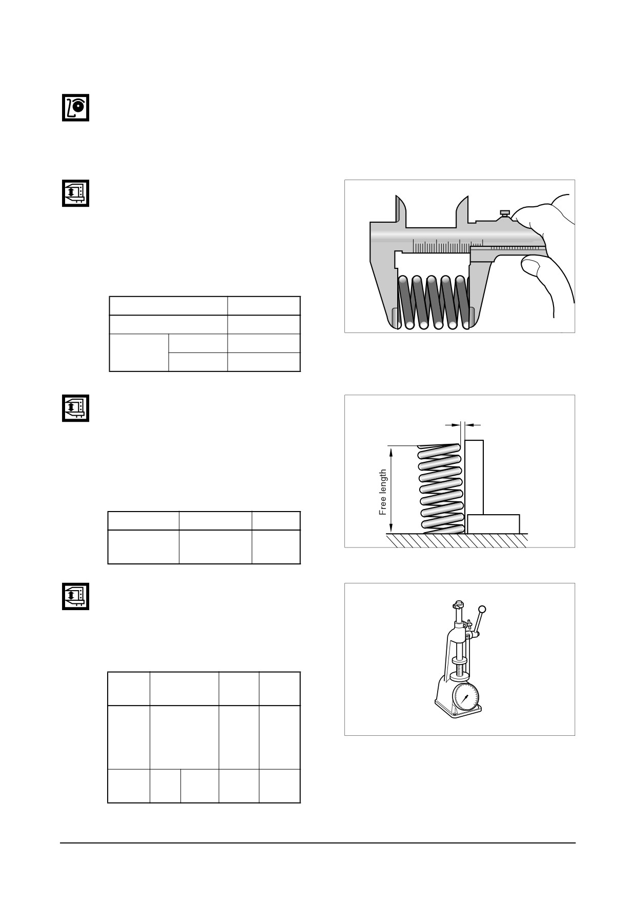
Valve spring
● Visual check
Visually check the exterior of the
valve springs for damage, and
replace if necessary.
● Valve spring free length
Use a vernier caliper to measure
the valve spring free length.
If the measured value is less than
the specified limit, the valve spring
must be replaced.
(mm)
Spring free Length
Standard
Intake valve
75.5
EJM2049I
Exhaust
Inner
65
valve
Outer
75.5
● Valve spring inclination
Use a surface plate and a square to
Inclination
measure the valve spring inclination.
If the measured value exceeds the
specified limit, the valve spring must
be replaced.
(mm)
Standard
Limit
Square
Valve spring
EJM2050I
1.0
2.0
Inclination
● Valve spring tension
Use a spring tester to measure the
valve spring tension if the measured
value is less than the specified limit,
the valve spring must be replaced.
Spring
Set Length
Limit
Spring tester
force
Valve Spring
Intake
Tension at 37
61.8 ~
EA0M4056
61.8 kg
valve
mm Set
68.3 kg
Length
Exhaus
36.1 ~
Inner
34 mm
36.1 kg
t valve
39.9 kg
Disassembly and Reassembly of Major Components
-
77 -
9.2.4. Rocker arm shaft assembly
1)
Rocker arm shaft
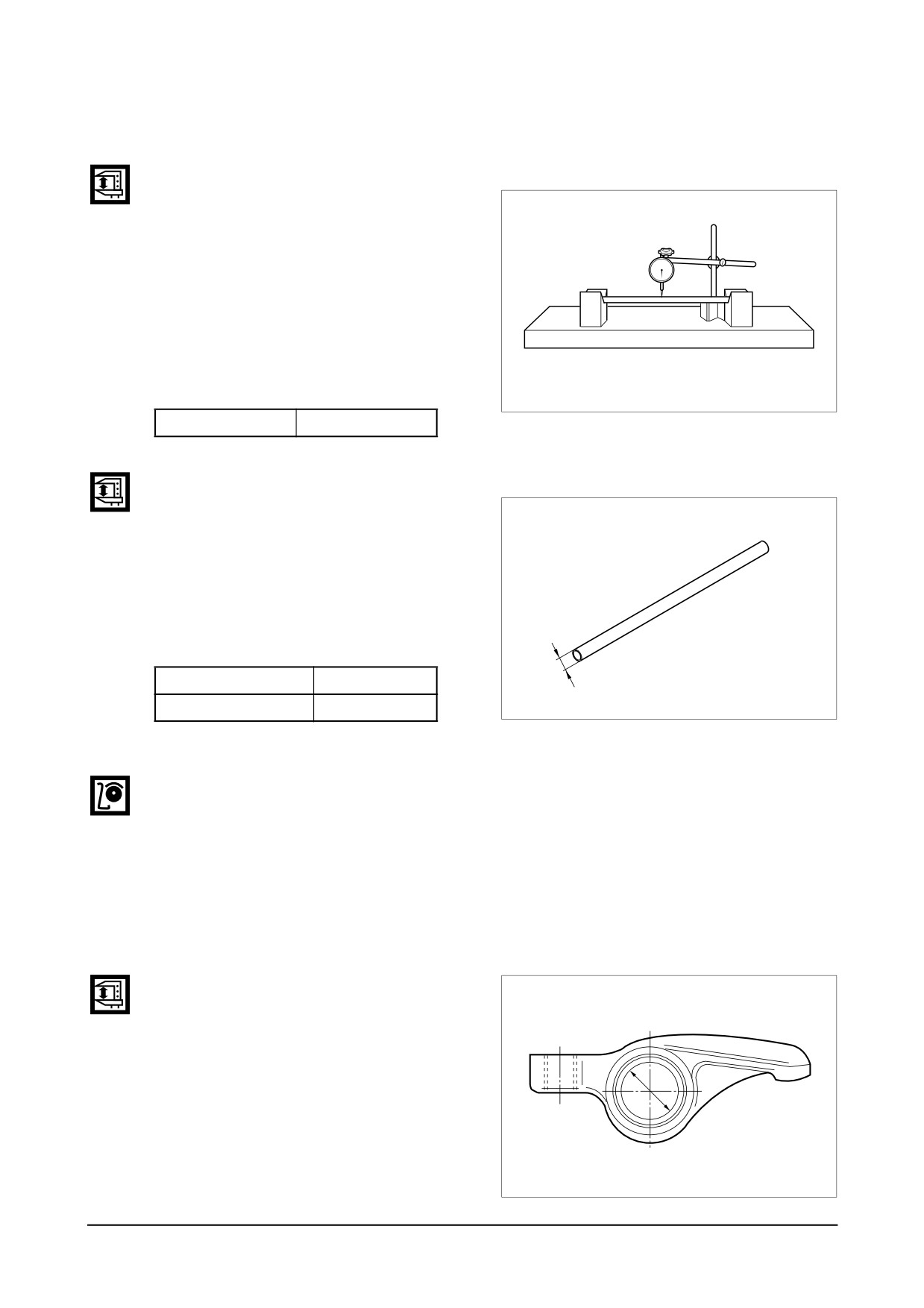
● Rocker arm shaft run-out
Place the rocker arm shaft on two V
blocks and inspect the shaft for
bend using a dial gauge.
If the amount of this run-out is
small, press the shaft with a bench
press to correct the run-out Replace
the shaft if the measured value
exceeds the limit.
(mm)
EDM2037I
Limit
0.2
● Rocker arm shaft diameter
With an outside micrometer, measure
the rocker arm shaft diameter at the
point where the rocker arms have
been installed.
Replace the rocker arm if the amount
of wear is beyond the specified limit.
(mm)
Standard
Limit
Ø23.978 ~ Ø23.959
Ø23.75
EA8M3002
2)
Rocker arm
● Visual check
Visually check the face of the rocker
arm in contact with the valve stem end
for scores and step wear. If the wear is
small, correct it with an oil stone or
grinding paper of fine grain size.
Rocker arm with a considerable amount
of step wear should be replaced.
● Diameter of the rocker arm bushing
Measure the inside diameter of the
rocker arm bushing with an inside
micrometer or vernier calipers, and
compare the measured values with
the rocker arm shaft diameter.
If the clearance exceeds the limit,
replace either bushing or shaft,
whichever worn more.
EA0M4059
D
-
78 -
isassembly and Reassembly of Major Components
<Clearance>
(mm)
Standard
Limit
0.020 ~ 0.093
0.2
3)
Tappet & push rod
● Clearance
Measure the clearance of the tappet
and tappet holes of the cylinder
block. If the value is beyond the
specified limit, replace tappets.
(mm)
Standard
Limit
0.035 ~ 0.077
0.15
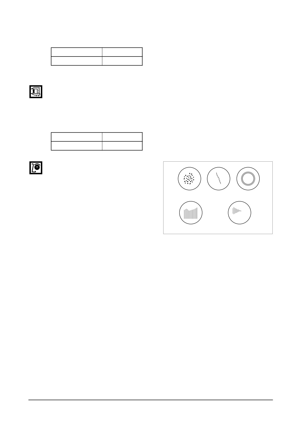
● Visual check of tappet
Visually check the face of the tap-
pets in contact with the cam for pit-
ting, scores or cracks, and replace if
(1) Unevenness
(2) Crank
(3) Normal
severely damaged. If the amount of
cracks or pitting is small, correct
with an oil stone or grinding paper.
Abnormal
EA0M4070
Disassembly and Reassembly of Major Components
-
79 -
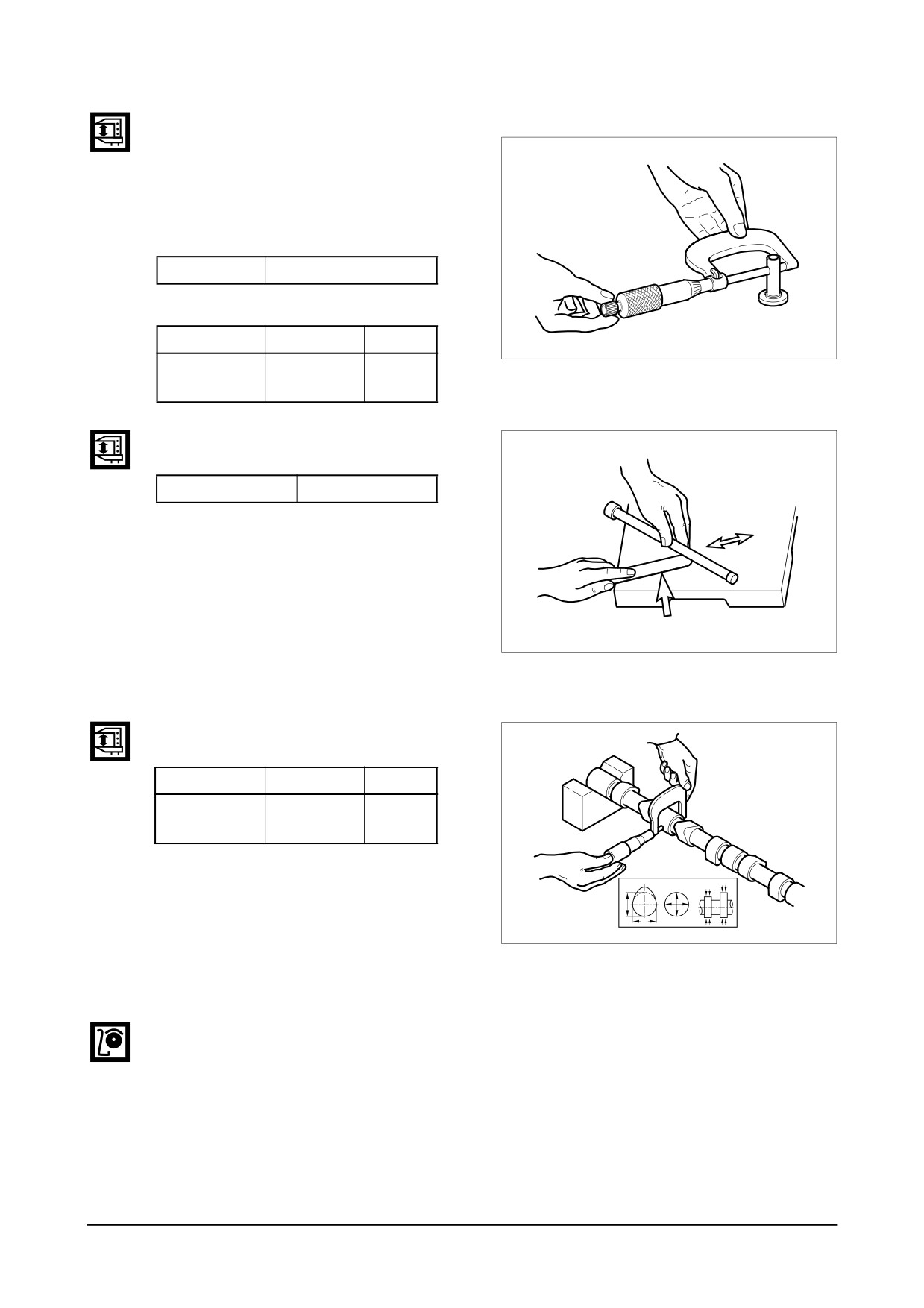
● Outside diameter
With an outside micrometer, mea-
sure the tappet outside diameter If
the measured value is beyond the
limit, replace tappets.
(mm)
Tappet Dia
Ø19.944 ~ Ø19.965
(mm)
Standard
Limit
EDM2061I
Tappet
0.035 ~
0.15
Clearance
0.077
● Push rod run-out
(mm)
Limit
0.3 or less
Use a feeler gauge to measure the
push rod run-out.
Roll the push rod along a smooth
flat surface as shown in the figure.
Feeler gauge
EA0M4073
9.2.5. Cam shaft
1) Cam
● Cam lobe height
(mm)
Standard
Limit
Cam journal
Ø59.86 ~
Ø59.52
diameter(A,B)
Ø59.88
Use a micrometer to measure the
I II
I II
A
cam journal diameter.
C
B
B
D
A
If the measured number is less than
EA0M4062
the specified limit, the camshaft
must replaced.
● Cam surface
Use a micrometer to measure the
cam journal diameter.
If the measured number is less than
the specified limit, the camshaft
must replaced.
D
-
80 -
isassembly and Reassembly of Major Components
2)
Cam shaft
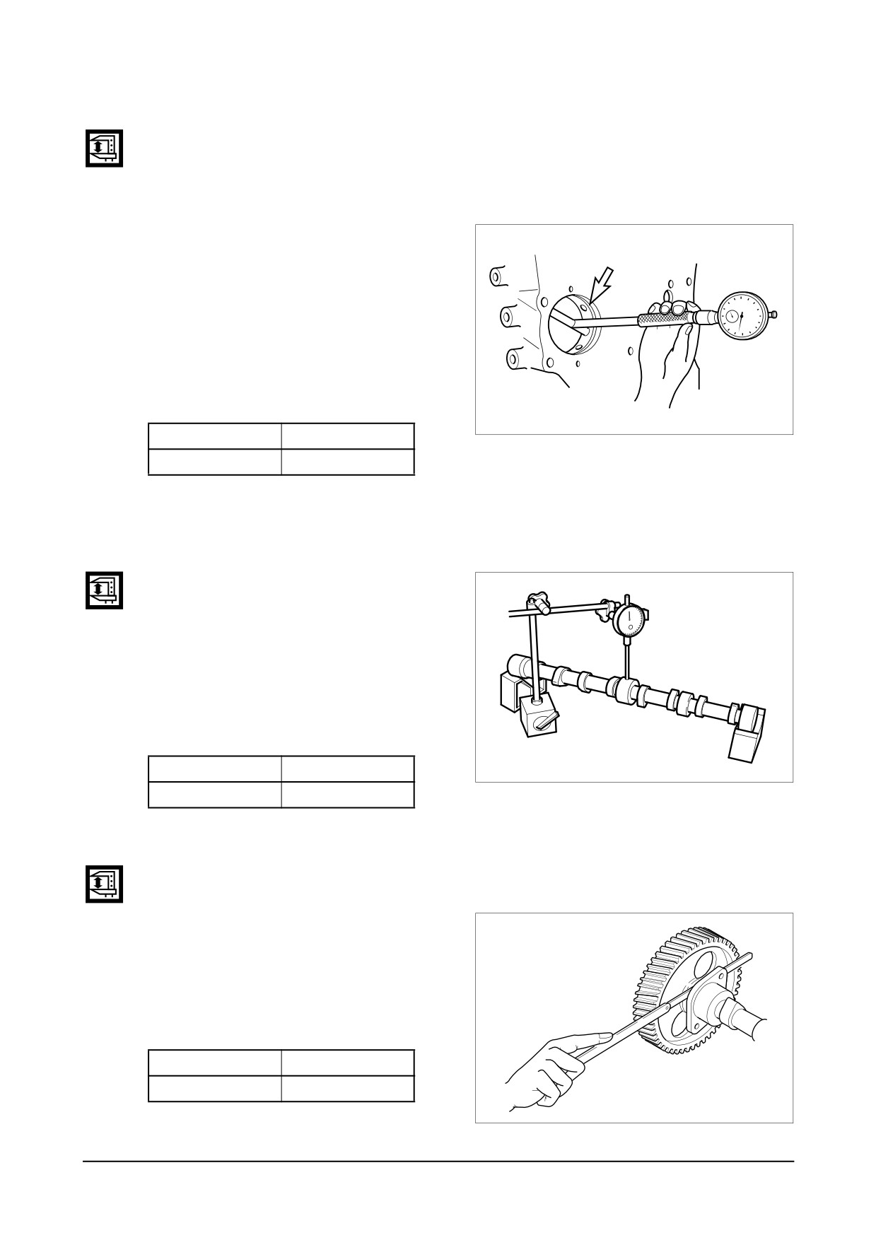
● Clearance between camshaft journal
& camshaft bush
- With an outside micrometer, mea-
sure the camshaft journal diameter.
- Measure the inside diameter of the
camshaft bushing on the cylinder
Camshaft bearing
block using a cylinder bore indicator,
and compare the measured value
with the camshaft outside diameter to
determine the clearance.
<Clearance>
(mm)
EA0M4063
Standard
Limit
0.050 ~ 0.128
0.2
Replace the bushing if the measured
value is beyond the specified limit.
● Run-out
Support the camshaft on two V
blocks and check for run-out using
a dial indicator. Correct or replace
the cam shaft if the amount of run-
out is beyond the value indicating
need for servicing.
(mm)
Standard
Limit
EA0M4066
0.05
0.2
3)
Cam shaft & play
● Push the thrust plate toward the
cam gear.
● With a feeler gauge, measure the
clearance between the thrust plate
and camshaft journal.
● If the end play is excessive, replace
the thrust plate.
(mm)
Standard
Limit
0.13 ~ 0.27
0.3
EA0M4067
Disassembly and Reassembly of Major Components
-
81 -
9.2.6. Crank shaft
1)
Defect check
● Visually check the crankshaft journal
and crank pins for scores or cracks.
● Using a magnetic particle test and
color check, inspect the crankshaft
for cracks, and replace the crank-
shaft which has cracks.
2)
Wear
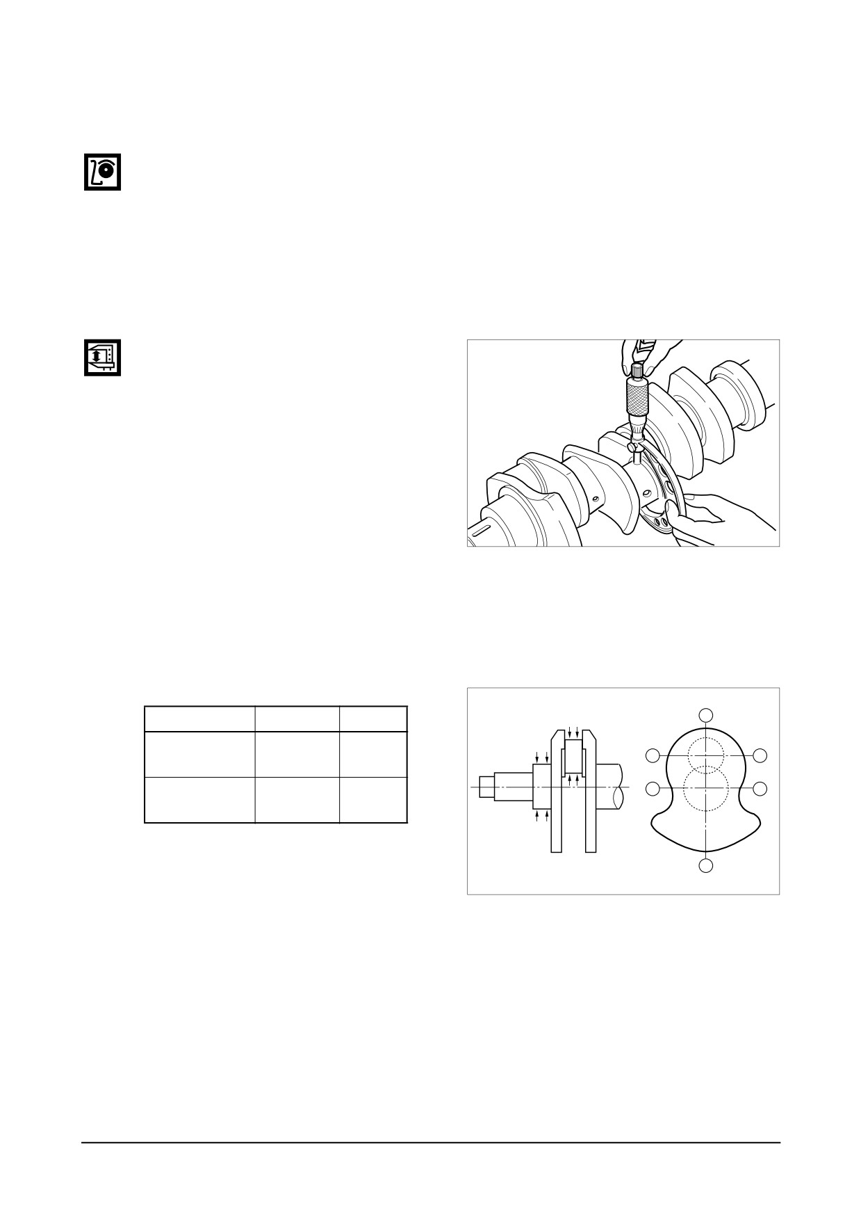
● With an outside micrometer mea-
sure the diameter of the crankshaft
journals and pins in the directions
as shown, and compare the mea-
sured values to determine the
amount of wear.
● If the amount of wear is beyond the
limit, have the crankshaft ground
and install undersize bearings. How-
EAMD057I
ever, if the amount of wear is within
the limit, you can correct the wear
using an oil stone or oiled grinding
paper of fine grain size. (Be sure to
use grinding paper which has been
immersed in oil.)
(mm)
Standard
Limit
A
Ø95.966 ~
Journal diameter
Ø94.966
B
B
Ø95.988
Ø82.966 ~
B
B
Pin diameter
Ø81.966
Ø82.988
A
EFM2047I
* Undersize bearings available
◆ Standard
◆ 0.25 (Inside diameter is 0.25 mm lesser than the standard size.)
◆ 0.50 (Inside diameter is 0.50 mm lesser than the standard size.)
◆ 0.75 (Inside diameter is 0.75 mm lesser than the standard size.)
◆ 1.00 (Inside diameter is 1.00 mm lesser than the standard size.)
Undersize bearings are available in 4 different sizes as indicated above, and the crankshaft
can be reground to the above sizes.
D
-
82 -
isassembly and Reassembly of Major Components
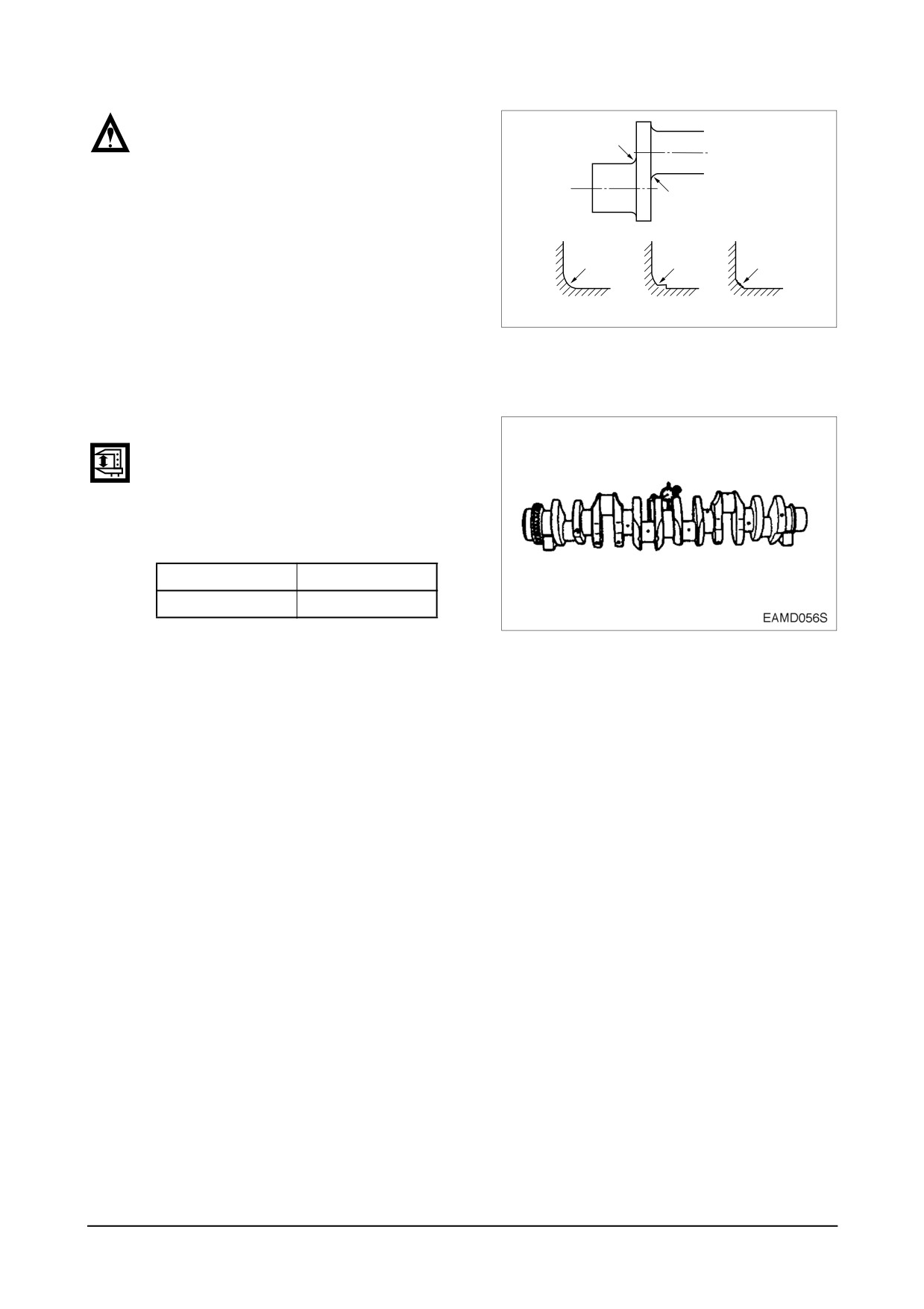
NOTE :
When regrinding the crankshaft as
" R "
described below, the fillet section
ëRí should be finished correctly.
" R "
Avoid sharp corners or insufficient
fillet.
" R "
" R "
" R "
* Standard values of "R”
0
Normal
Poor
Poor
① Crankshaft Pin "R" : 4.5
-0.2
EFM2048I
0
② Crankshaft journal "R" : 4
-0.2
3) Crankshaft run-out
● Support the crankshaft on V blocks.
● Turn the crankshaft with a dial indi-
cator placed on the surface plate
and take the amount of crankshaft
run-out.
(mm)
Standard
Limit
0.05
0.1
Disassembly and Reassembly of Major Components
-
83 -
9.2.7. Crank shaft bearing & connection rod bearing
1)
Visual check
Visually check the crankshaft bearing
and connecting rod bearing for scores,
uneven wear or damage.
2)
Oil clearance between crankshaft & bearing
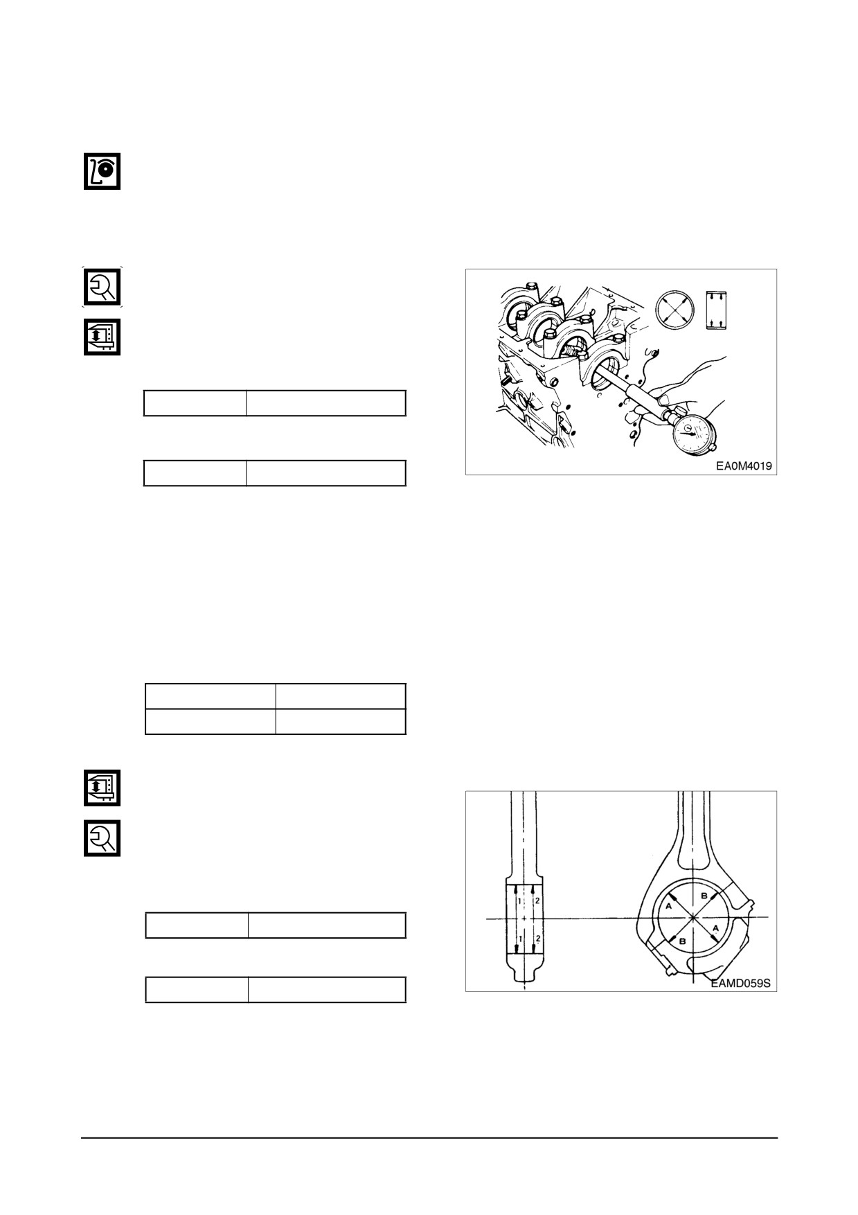
● Main bearing clearance (Method 1)
Install the main bearing in the cylinder
block, tighten the bearing cap to
specified torque, then measure the
inside diameter.
Torque
30 kgm
(mm)
Standard Dia.
Ø96.06 ~ Ø96.108
Compare the two values obtained
through measurement of main bearing
inside diameter with the outside diame-
ters of crankshaft journals to determine
the oil clearance.
<Main bearing oil clearance>
(mm)
Standard
Limit
0.072 ~ 0.142
0.25
● Connecting rod bearing clearance
Install the connecting rod bearing in
the connecting rod bearing cap,
tighten the connecting rod cap bolts
to the specified torque, then mea-
sure the inside diameter.
Torque
28 kgm
(mm)
Standard Dia.
Ø83.02 ~ Ø83.092
-
D
84 -
isassembly and Reassembly of Major Components
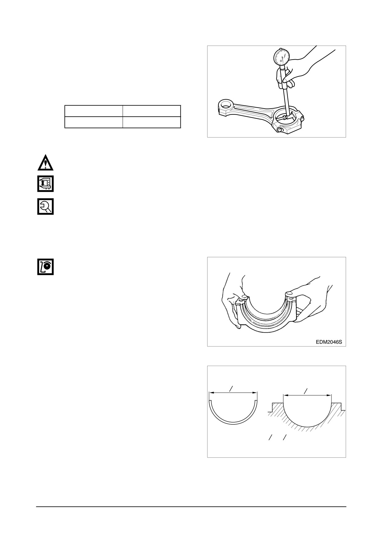
Compare the two values obtained
through measurement of connecting
rod bearing inside diameter with the
outside diameters of crankshaft pins
to determine the oil clearance.
(mm)
Standard
Limit
0.049 ~ 0.119
0.20
EAMD060I
● If the clearance deviates from the specified range, have the crankshaft journals and pins
ground and install undersize bearings.
● Connecting rod bearing clearance (Method 2 : with plastic gauge)
Assemble the crankshaft on the cylinder block and put the plastic gauge on journal and pin
of crankshaft and then after assembling bearing cap, tighten the bolts at the specific torque.
Again after disassembling the bearing cap by removing the bolts, take out the flatted plastic
gauge and measure the width of plastic gauge by means of plastic gauge measuring scale.
This is the oil clearance.
3)
Bearing spread and crush
● Inspection
Check to see that the bearing
requires a considerable amount of
finger pressure at reassembly opera-
tion.
O A
O B
Spread = O A - O B
EDM2047I
Disassembly and Reassembly of Major Components
-
85 -
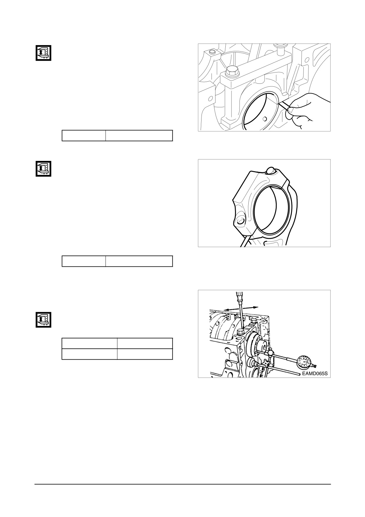
● Crankshaft bearing crush
Install the bearing and cap in the
cylinder block, retighten the bolts to
specified torque, unscrew out one
bolt completely, then measure the
clearance between the bearing cap
and cylinder block using a feeler
gauge.
(mm)
EA6M063I
Standard Dia.
0.15 ~ 0.25
● Connecting rod bearing crush
Install the bearing and cap in the
connecting rod big end, retighten
the bolts to specified torque,
unscrew out one bolt completely,
then
measure the
clearance
between the bearing cap and con-
necting rod big end using a feeler
gauge.
EA6M064I
(mm)
Standard
0.086 ~ 0.116
4)
crank shaft end play
● Assemble the crankshaft to the cyl-
inder block.
● With a dial gauge, measure crank-
shaft end play.
(mm)
Standard
Limit
0.15 ~ 0.325
0.5
-
D
86 -
isassembly and Reassembly of Major Components
9.2.8. Piston
1) Visual check
Visually check the pistons for cracks,
scuff or wear, paying particular atten-
tion to the ring groove.
2) Clearance between the piston &
cylinder liner
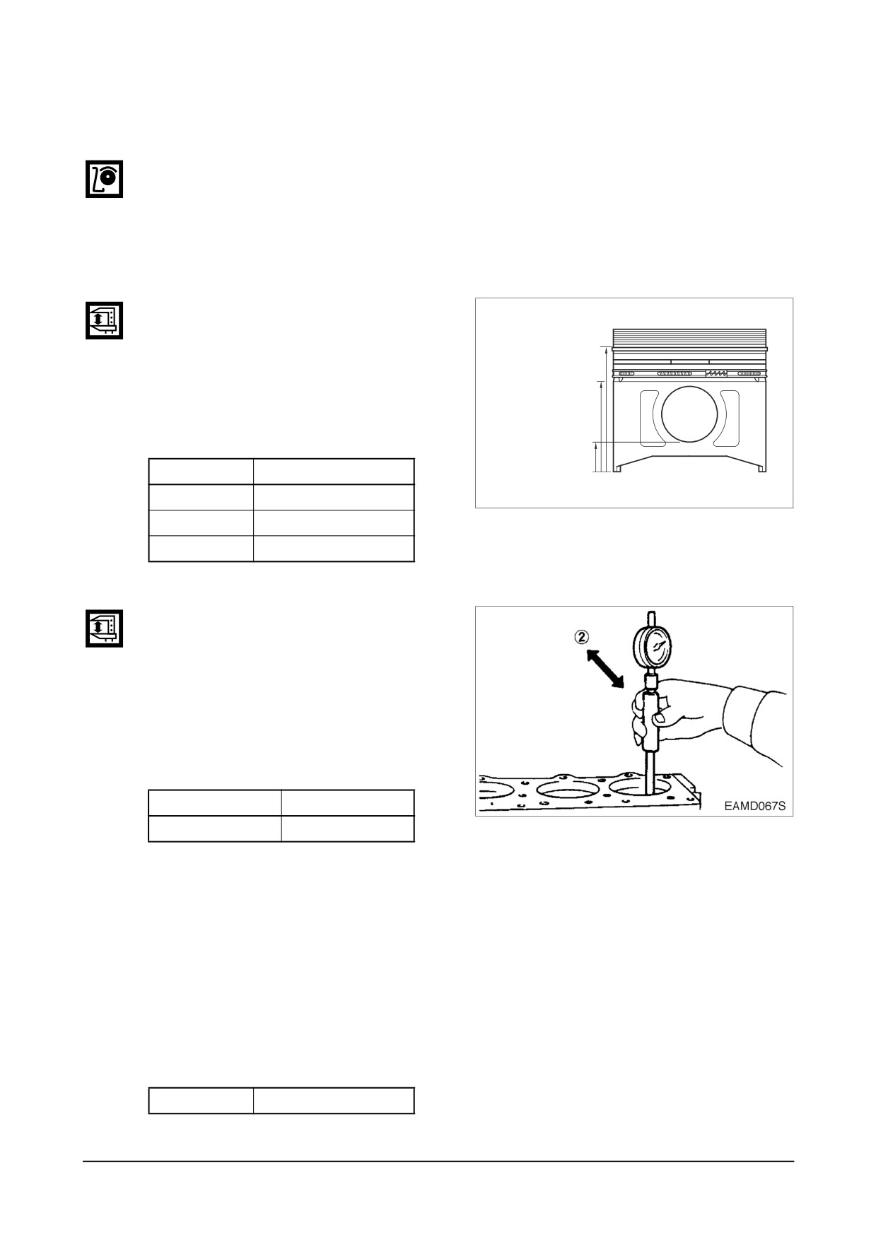
● With an outside micrometer, measure
Position of measuring
the piston outside diameter at the
outside diameter
points
D1(18mm),
D2(88mm),
D3(124mm)
D3(124mm) away from the lower end
of piston skirt in a direction at a right
D2(88mm)
angle to the piston pin hole.
(mm)
D1(18mm)
Point
Standard Dia.
D1(18mm)
Ø122.870 ± 0.007
EI6OM017
D2(88mm)
Ø122.750 ± 0.009
D3(124mm)
Ø122.450 ± 0.010
● Using a cylinder bore gauge, measure
cylinder liner inside diameter at
3
points (cylinder top ring contacting face,
middle, and oil ring contacting face on
BDC) in a direction at an angle of 45.
Take the mean value with the largest
and smallest values excepted.
(mm)
Standard
Limit
Ø123 ~ Ø123.023
Ø123.223
● The clearance is computed by subtract-
ing the piston outside diameter from
the cylinder liner inside diameter.
Replace either piston or cylinder liner,
whichever damaged more, if the clear-
ance is beyond the specified limit.
<Clearance between piston and
liner>
(mm)
Standard
0.114 ~ 0.169
Disassembly and Reassembly of Major Components
-
87 -
9.2.9. Piston rings
1)
Visual check
Replace the piston rings with new ones
if detected worn or broken when the
engine is overhauled.
2)
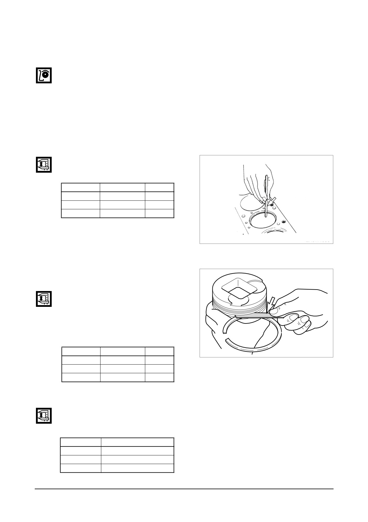
Piston ring gap
● Insert the piston ring into the upper
portion of the cylinder liner bore so
that it is held at a right angle to the
cylinder liner wall.
● Measure the piston ring gap with a
feeler gauge.
(mm)
Standard
Limit
Top ring
0.30 ~ 0.45
1.5
Feeler gauge
2nd ring
1.0 ~ 1.2
2.0
Oil ring
0.30 ~ 0.50
1.5
Replace piston rings with new ones if
the gap is beyond the limit
EA0M4033
3)
Piston ring side clearance
● Fit the compression ring and oil ring
in the piston ring groove.
Feeler gauge
● With a feeler gauge, measure side
clearance of each ring, and replace
either the ring or piston if the mea-
sured value is beyond the specified
limit.
(mm)
Standard
Limit
EA4M2007
Top ring
0.105 ~ 0.155
2nd ring
0.07 ~ 0.102
0.15
Oil ring
0.05 ~ 0.085
0.15
4)
Piston ring tension
With a tension tester, measure piston
ring tension. Replace the piston ring if
the measured value is beyond the limit.
Standard
Top ring
2.27 ~ 3.41 kg
2nd ring
2.0 ~ 3.0 kg
Oil ring
4.03 ~ 5.57 kg
-
D
88 -
isassembly and Reassembly of Major Components
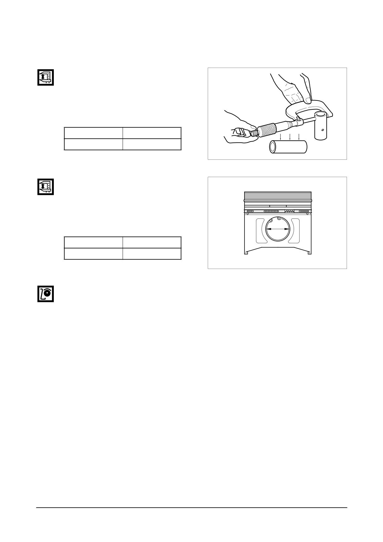
9.2.10. Piston pin
1)
Wear
Measure the amount of wear on the
piston pin at the points as shown.
The measured values are beyond the
limit
(0.005 mm or greater), replace
the pin
(mm)
Standard
Limit
Ø44.995 ~ Ø45
Ø44.990 or less
EA0M4031
2)
Clearance
Measure the clearance between the
piston pin and connecting rod bush-
ing, and replace either of them,
whichever damaged more, if the mea-
sured value is beyond the limit.
(mm)
Standard
Limit
0.003 ~ 0.009
0.011
EA3M2047
3)
Condition check
Check the engaged condition of the
piston and piston pin. If it is possible
to force the pin into the piston heated
with piston heater, the piston is nor-
mal.
When replacing the piston, be sure to
replace the piston pin together.
Disassembly and Reassembly of Major Components
-
89 -
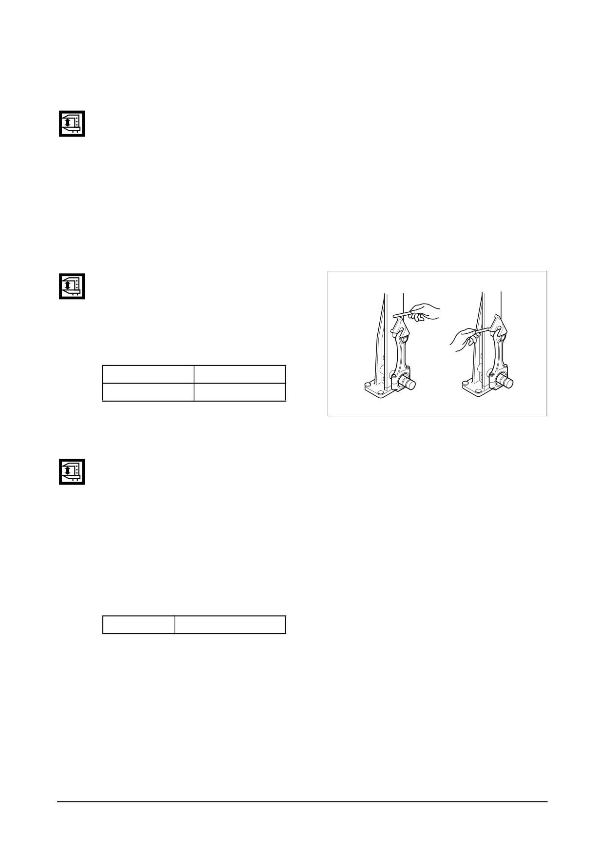
9.2.11. Connecting rod
1)
Distorsion
Check the connecting rod for distor-
tion. As shown in the figure below,
install the connecting rod to the con-
necting rod tester, and check for dis-
tortion using a feeler gauge. If the
connecting rod is found distorted,
never re-use it but replace with a new
one.
2)
Holes alignment (parallelism)
Measure the alignment of the con-
necting rod piston pin bushing holes
with connecting rod big end holes. At
this time also, use both connecting
rod tester and feeler gauge.
(mm)
Standard
Limit
0.05
0.1 or less
EA0M4034
3)
Wear
● Assemble the connecting rod to the
crankshaft and measure connecting
rod big end side clearance using a
feeler gauge.
● Assemble the connecting rod to the
piston and measure connecting rod
small end side clearance.
● If the measured values are beyond
the limit, replace the connecting rod.
(mm)
Limit
0.5
D
-
90 -
isassembly and Reassembly of Major Components
9.3. Reassembly
9.3.1. General precautions
● Wash clean all the disassembled parts, particularly oil and water ports, using compressed air,
then check that they are free from restrictions.
● Arrange the general and special tools in order for engine assembly operation.
● To wet each sliding part, prepare the clean engine oil.
● Prepare service materials such as sealant, gaskets, etc.
● Discard used gaskets, seal rings, and consumable parts, and replace with new ones.
● Apply only the specified torque for bolts in the specified tightening order and avoid over-tight-
ening.
● Be sure to check that all the engine parts operate smoothly after being reassembled.
● Check the bolts for looseness after preliminary reassembly.
● After completing the engine reassembly operation, check if there is missing parts or shortage
of parts.
● Keep your hands clean during the working.
9.3.2. Cylinder block
Cover the floor of the workshop with wood plate or thick paper to prevent damage to the cylin-
der head and place the cylinder block with the head fitting surface facing downward.
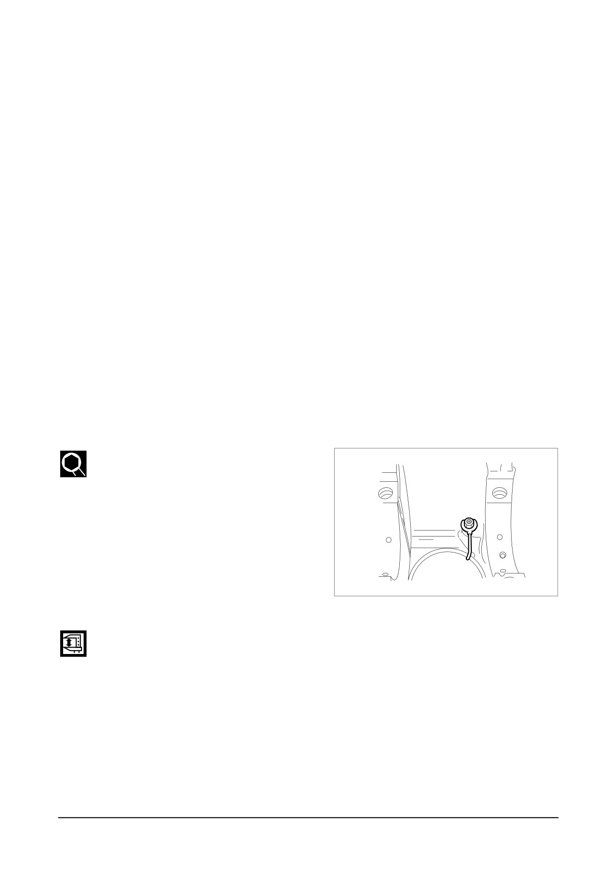
9.3.3. Oil spray nozzle
● Tighten and assemble the oil spray
nozzle flange with fixing bolts using
the spray
nozzle jig.
EDM3053I
9.3.4. Tappet and cam shaft
● Undercool a new bush with dry ice
for about
2 hours and press it into
position in the cylinder block using a
bench press. After the pressing oper-
ation, measure the inside diameter of
the cam bush to check if it is not
deformed.
Disassembly and Reassembly of Major Components
-
91 -
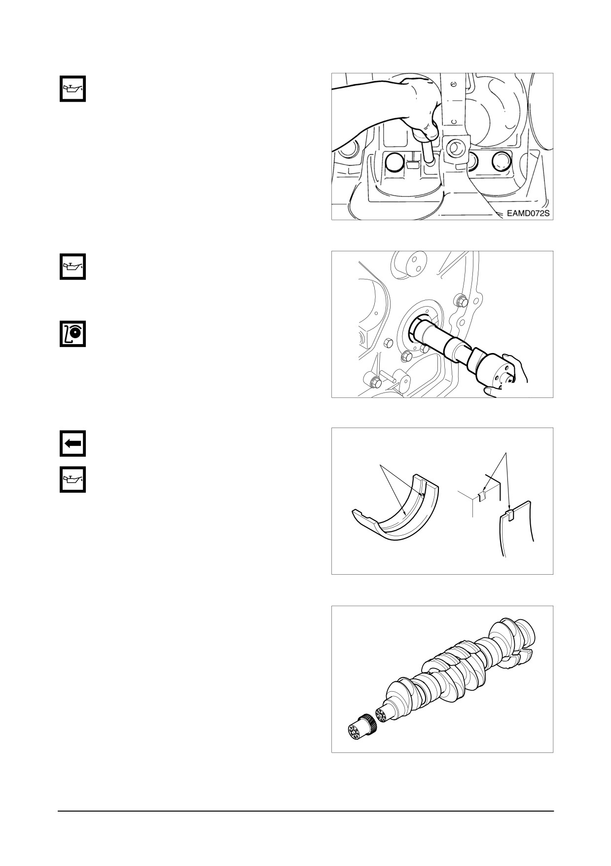
● Apply engine oil to the entire face of
the tappets and slide them into the
tappet holes on the cylinder block.
● Wet the cam bush inside diameter
and camshaft with oil, and carefully
assemble them while turning the cam-
shaft.
● Check to see that the camshaft
rotates smoothly.
EDM2060I
9.3.5. Crankshaft
● Install the main bearing machined
Key groove
with two holes in the cylinder block
Oil port and passage
so that the key is aligned with the
key groove, then apply oil to the
bearing surface.
EA0M4083
● Heat the crankshaft gear for at least
10
minutes to 120C, then apply
sealant
(Loctite
# 641) to the inside
wall of the heated crankshaft gear
evenly before inserting it to the end
of crankshaft.
EA8M3014
-
D
92 -
isassembly and Reassembly of Major Components
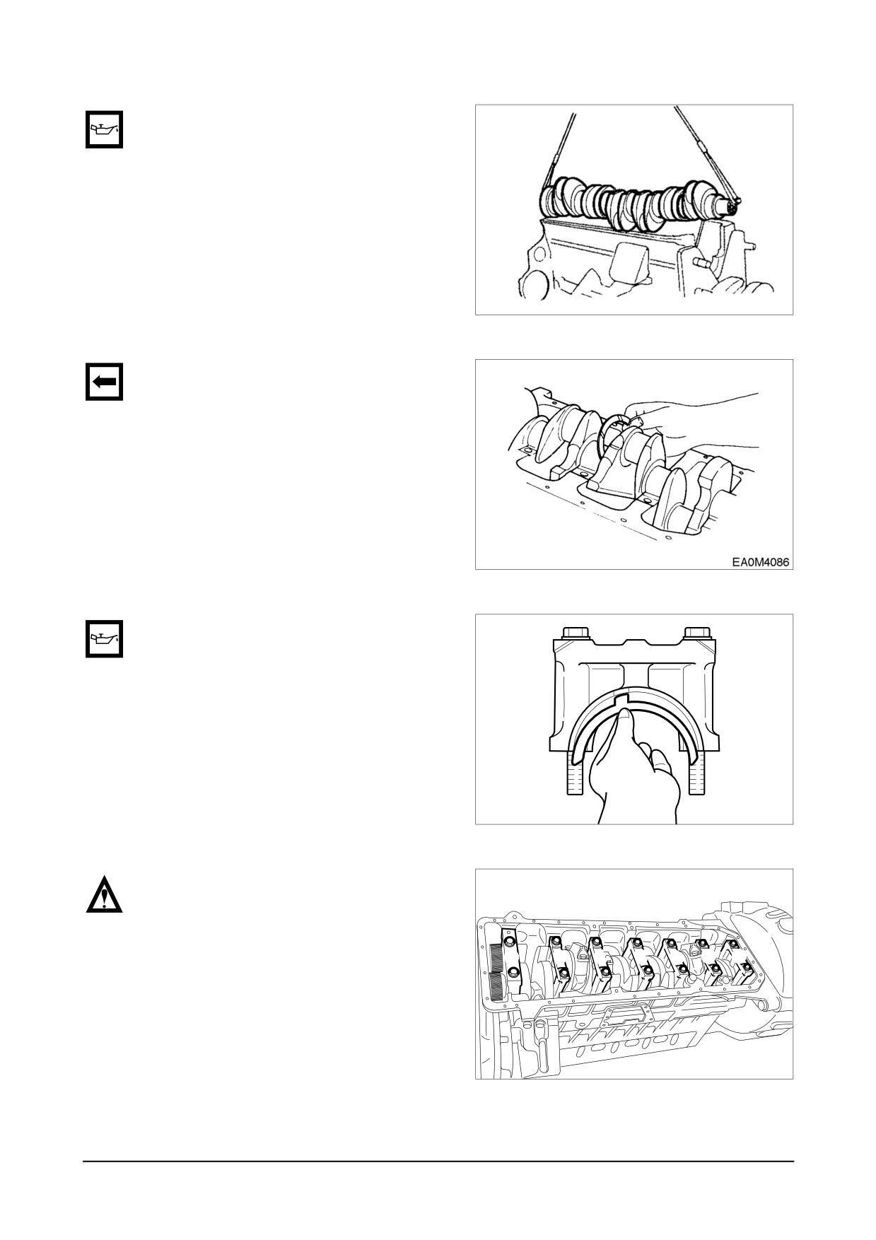
● Semi-tighten a bolt at both sides of
the crankshaft, apply engine oil to
journals and pins, then assemble the
crankshaft with the cylinder block by
tightening the fixing bolts.
EAMD075S
● Install the oiled thrust washers with
the oil groove facing outward.
● Install the bearing and thrust washers
to the bearing cap and apply oil to
the bearing and thrust washers.
EAMD077I
● Install the bearing cap by matching
the cylinder block No. with the bear-
ing cap No.
7
6
5
4
3
2
1
EQM3058I
Disassembly and Reassembly of Major Components
-
93 -
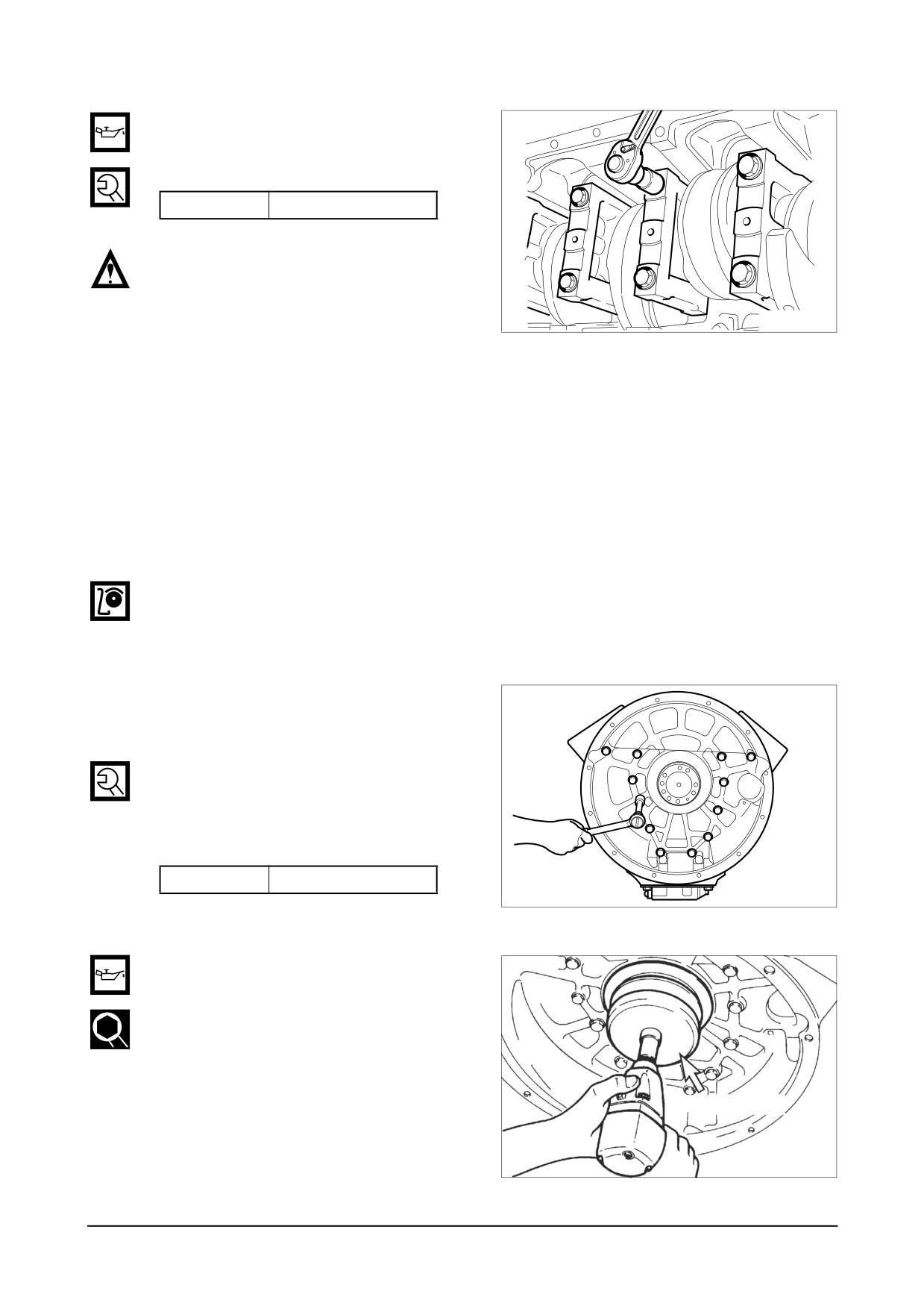
● Apply oil to the entire part of the bear-
ing cap bolts, then tighten in tightening
sequence to specified torque.
Torque
30 kgm
● After semi-tightening both bolts
evenly, tighten them diagonally speci-
fied torque using a torque wrench as
EQM3059I
follows.
<Tightening order>
(1) First stage : Coat engine oil over the bolts.
(2) Second stage : Temporary assemble the bolts about 1 ~ 2 threads
(3) Third stage : With impact wrench, tighten up to about 15 kg.m
(4) Fourth stage : With torque wrench, tighten up to about 25 kg.m
(5) Fifth stage : By means of torque wrench, tighten finally in the specified torque. (30 kgm).
● Tighten the bearing cap in the sequence of
4-3-5-2-6-1-7.
● Check to see that the assembled crankshaft turns smoothly.
9.3.6. Flywheel housing
● Temporarily install the guide bar on
the cylinder block.
● Apply gasket to the cylinder block.
● Using the dowel pin and guide bar,
install
the flywheel housing and
tighten the fixing bolts in a diagonal
sequence to specified torque.
Torque
12 kgm
EQM3060I
9.3.7. Rear oil seal
● Apply lubricating oil to the outside of
theoil seal and flywheel housing
inside diameter and fit them over the
crank shaft, then assemble the oil
seal using an oil seal fitting jig.
Oil seal fitting jig
EA8M3003
-
D
94 -
isassembly and Reassembly of Major Components
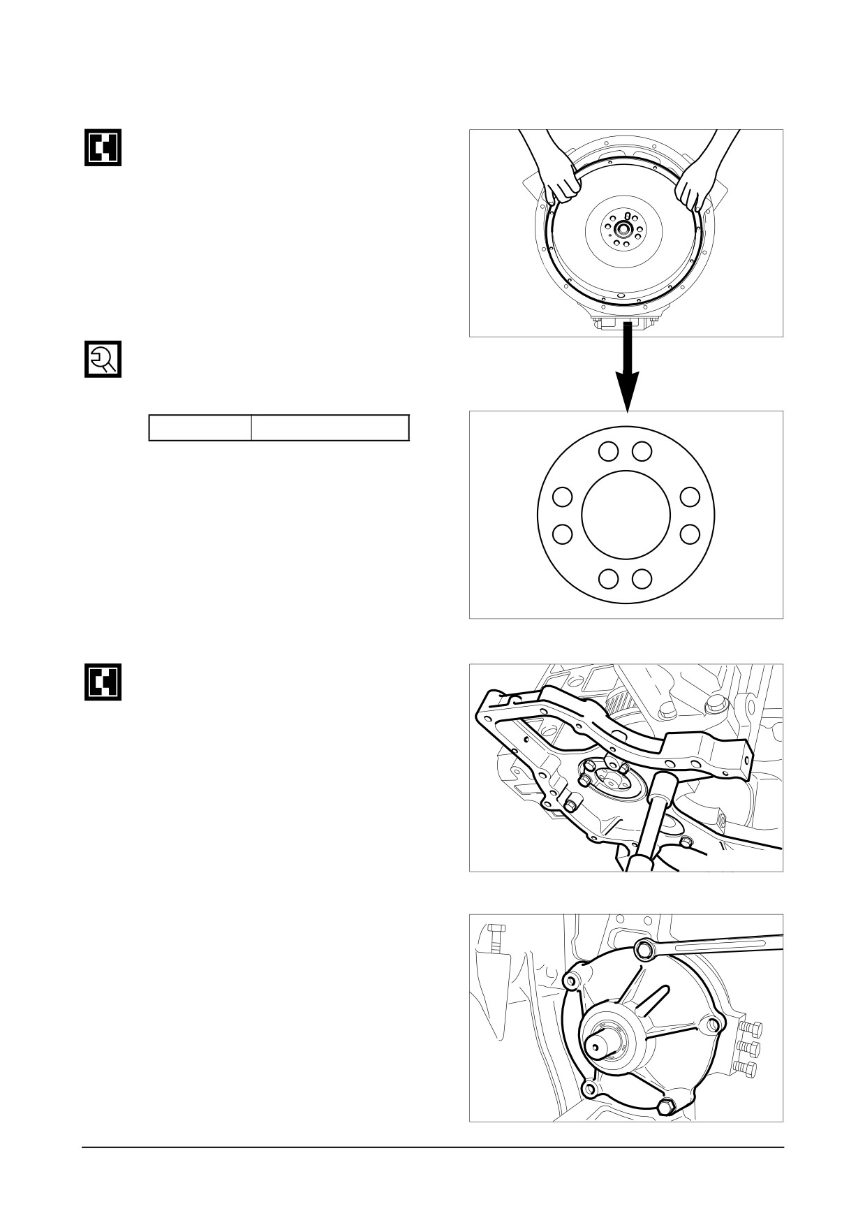
9.3.8. Flywheel
● Install a guide bar into a bolt hole on
the crank shaft, and lift the flywheel to
align the dowel pin with the pin hole
on the flywheel for temporary assem-
bly operation.
● Install bolts in the remaining holes,
take out the guide bar, then install a
bolt in the hole where the guide bar
had been inserted.
EAMD081I
● Tighten the fixing bolts using a torque
wrench in a diagonal sequence to
specified torque.
Torque
18 kgm
4
8
6
1
2
5
7
3
EAMD097I
9.3.9. Timing gear case
● Mount gasket using dowel pin on the
cylinder block.
● Install the timing gear case by align-
ing the dowel pin with the dowel pin
hole on the timing gear case.
EAMD082I
9.3.10. Fuel injection pump drive gear assembly
● Mount gasket by aligning the bolt
holes with the pin holes on the
bearing housing.
● Tighten up the fixing bolts in the
direction of fuel injection pump.
EAMD027I
Disassembly and Reassembly of Major Components
-
95 -
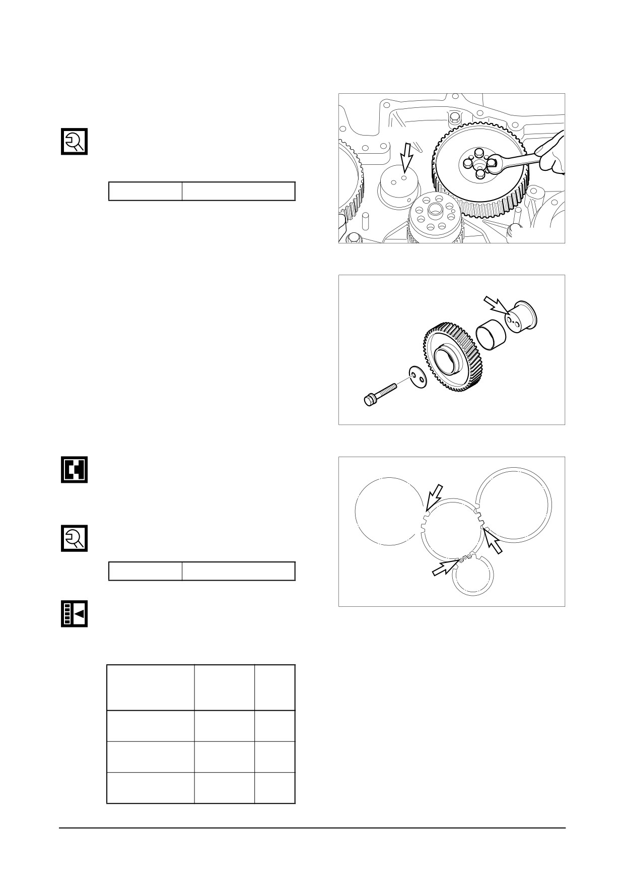
9.3.11. Timing gear
● Install the oil pump idle gear onto the
No.7 bearing cap.
● Install a thrust washer over the cam-
Idle gear pin
shaft and assemble the cam gear by
aligning it with camshaft key groove.
Torque
3.1 kgm
EAMD083I
● With the oil port on the idle gear pin
facing the cylinder block, install the
Idle gear pin
idle gear pin.
EA8M3004
● Install the idle gear by coinciding the
marks impressed on the crank gear,
Mark "2"
cam gear, fuel injection pump drive
Fuel injection
Cam gear
gear, and idle gear.
pump drive gear
1 1
2
2
2
1
● Install a thrust washer on the idle
Idle gear
gear and tighten to specified torque.
Mark "1"
Torque
7.4 kgm
Crank
Mark "0"
gear
EA8M3005
● Check and adjust the amount of
backlash between gears using a
feeler gauge.
(mm)
Measuring
position
Backlash
Limit
(between)
Cam gear &
0.16 ~ 0.28
0.35
idle gear
Crank gear &
0.16 ~ 0.28
0.35
idle gear
Injection pump &
0.16 ~ 0.28
0.35
idle gear
-
96 -
Disassembly and Reassembly of Major Components
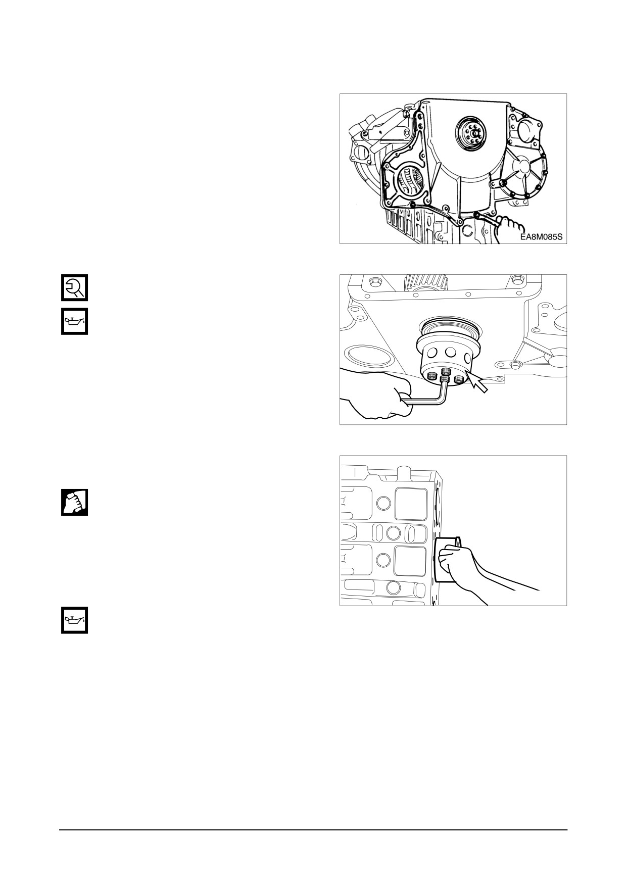
9.3.12. Timing gear case cover
● Install dowel pin on the timing gear
case.
● Mount a gasket by aligning the fixing
bolt holes with those on the gasket.
● Align the dowel pin with the cover pin
hole, then install the cover with light
tap.
● Tighten the fixing bolts beginning with
the oil pan fitting face.
9.3.13. Front oil seal
● Apply lubricating oil to the outside of
the oil seal and timing gear case
inside diameter and fit them over the
crankshaft, then assemble the oil seal
using an oil seal fitting jig.
Oil seal fitting jig
EAMD086I
9.3.14. Cylinder liner
● Stand the cylinder block so that the
flywheel faces downward.
● Thoroughly clean the liner flange fit-
ting surface and bore inside with
compressed air to prevent the entry
of foreign substances.
● After the cleaning operation, make
the cylinder liner dried up and push it
into the cylinder block by hand.
EAMD087I
● Wet the liner inside diameter with
engine oil.
Disassembly and Reassembly of Major Components
-
97 -
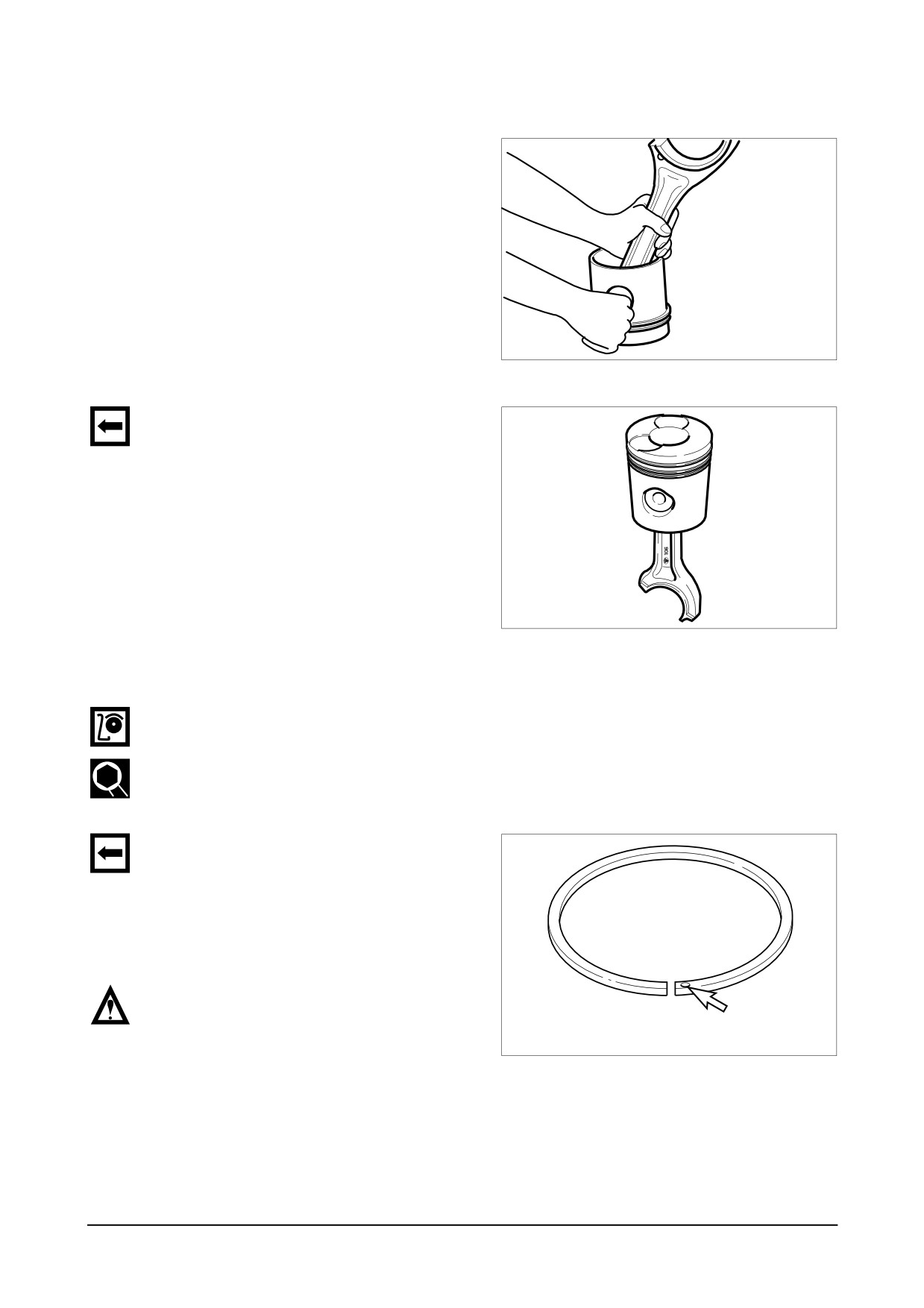
9.3.15. Piston & connecting rod
● Align the piston pin hole with the
oiled connecting rod small end and
press the piston pin
(by lightly tap-
ping with a rubber hammer) to
assemble the connecting rod with the
piston.
EAMD088I
● Noting the direction of the piston,
make the longer side (machined with
key groove on the bearing) of the
connecting rod big end and the mark
of “DI” impressed on the inside of the
piston face each other in opposite
directions. On the piston head sur-
face, the longer side of connecting
rod big end is in opposite direction
EAMD089I
from the valve seating surface as well
as in the same direction with the nar-
row margin of combustion chamber.
● Install the snap rings and check to
see that it is securely assembled.
● Install the piston ring in the piston
using piston ring pliers.
● Identify the mark "Y" or "TOP" on the
ring end to prevent the top and bot-
tom of the piston ring is interchanged
each other and make the marked top
face upward.
NOTE :
Be sure to make the piston ring end
Marked with the name of piston ring
manulacturing company
marked face("Y" or "TOP") upward.
EAMD090I
-
98 -
Disassembly and Reassembly of Major Components
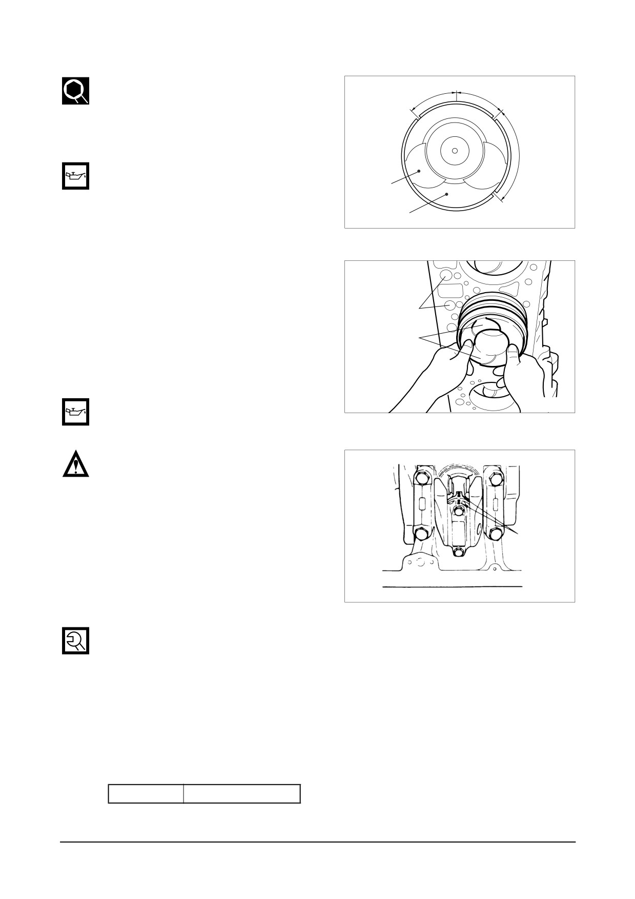
● Adjust the angle among individual pis-
O
45O
45
ton ring gaps to
90° and fit a piston
2nd ring gap
Top ring gap
assembling jig onto the piston, Use
care not to match the ring gaps with
the pin direction.
90O
● Install the bearing by aligning it with
the connecting rod key groove and
Piston pin
apply oil to the bearing and piston.
Oil ring gap
Piston
EA8M3006
● Position the valve seating surface
toward the tappet hole and insert the
piston with hand.
Tappet hole
Use care not to damage the cylinder
liner and piston, and slightly lift and
Valve seating
insert the piston into the cylinder so
that the ring may not be damaged by
the fillet of the liner.
● Install the bearing in the connecting
EAMD092I
rod cap and apply oil.
● Make sure that the manufacture serial
numbers impressed on the connecting
rod cap and connecting rod big end
are identical, and install the connect-
ing rod cap by aligning it with dowel
Serial No.
pin.
EA0M4092
● Wet the fixing bolts with oil, semi-tighten them with hand, tighten them to specified torque
using a torque wrench as follows.
<Tightening order>
(1) First stage : Coat engine oil over bolts
(2) Second stage : Temporary screw the bolt about 1 ~ 2 threads
(3) Third stage : With torque wrench, tighten at about 15 kgm
(4) Fourth stage : With torque wrench, tighten up to about 22 kgm
(5) Fifth stage : Finally, tighten in the specified torque 28kg.m with torque wrench.
Torque
28 kgm
Disassembly and Reassembly of Major Components
-
99 -
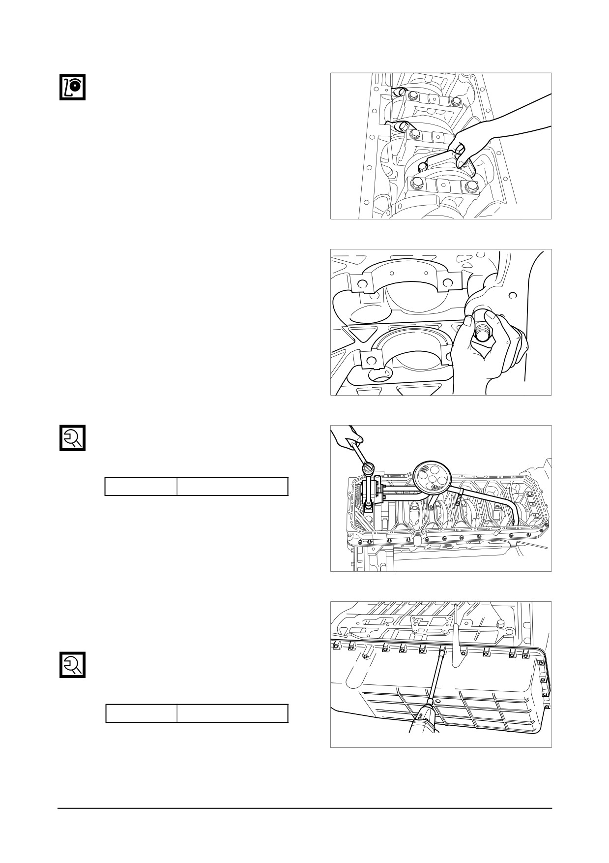
● Move the bearing cap with hand, and
release and reassemble it if no move-
ment is detected.
EAMD094I
9.3.16. Relief valve
● Assemble the relief valve.
EAMD036I
9.3.17. Oil pump and oil pipe
● Install a dowel pin in the No.7 bear-
ing cap, then assemble the oil pump
with specified torque.
Torque
4.4 kgm
● Assemble the oil suction pipe with the
delivery pipe, then install the bracket
on the bearing cap.
EAMD095I
9.3.18. Oil pan
● Mount gasket and put the oil pan
thereon.
● Place stiffeners and tighten bolts.
● Align the bolt holes with gasket holes
to prevent damage to the gasket and
tighten to specified torque.
Torque
2.2 kgm
EAMD034I
D
-
100 -
isassembly and Reassembly of Major Components
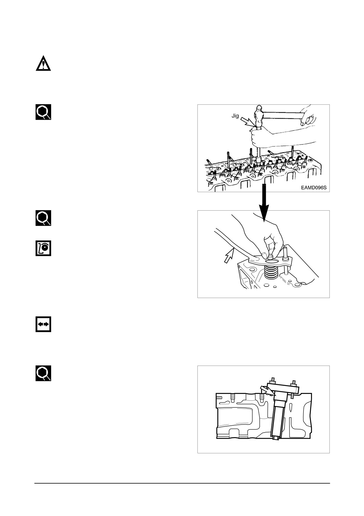
9.3.19. Intake & exhaust valves
● Identify the marks of
“IN” and
“EX”
impressed on the valve head before
assembling the valve with the valve
head.
● With a valve stem seal fitting jig,
assemble the valve stem seal with
the valve guide.
● After installing valve springs and
spring retainer, press the retainer with
a jig, then install cotter pin.
● Tap the valve stem lightly with a rub-
ber hammer to check that the valve
is assembled correctly.
Valve spring
compressor
EA0M4007
9.3.20. Nozzle tube
● Apply sealant
(LOCTITE
#
620) to
the nozzle tube and place the O-ring
over the cylinder head fitting face on
the nozzle tube, then install the noz-
zle tube in the cylinder head.
● Install a guider of the nozzle tube
insert assíy
(Guider
+ Expander) the
Guider
cylinder head, then tighten the nozzle
fixing nuts.
EAMD098I
Disassembly and Reassembly of Major Components - 101 -
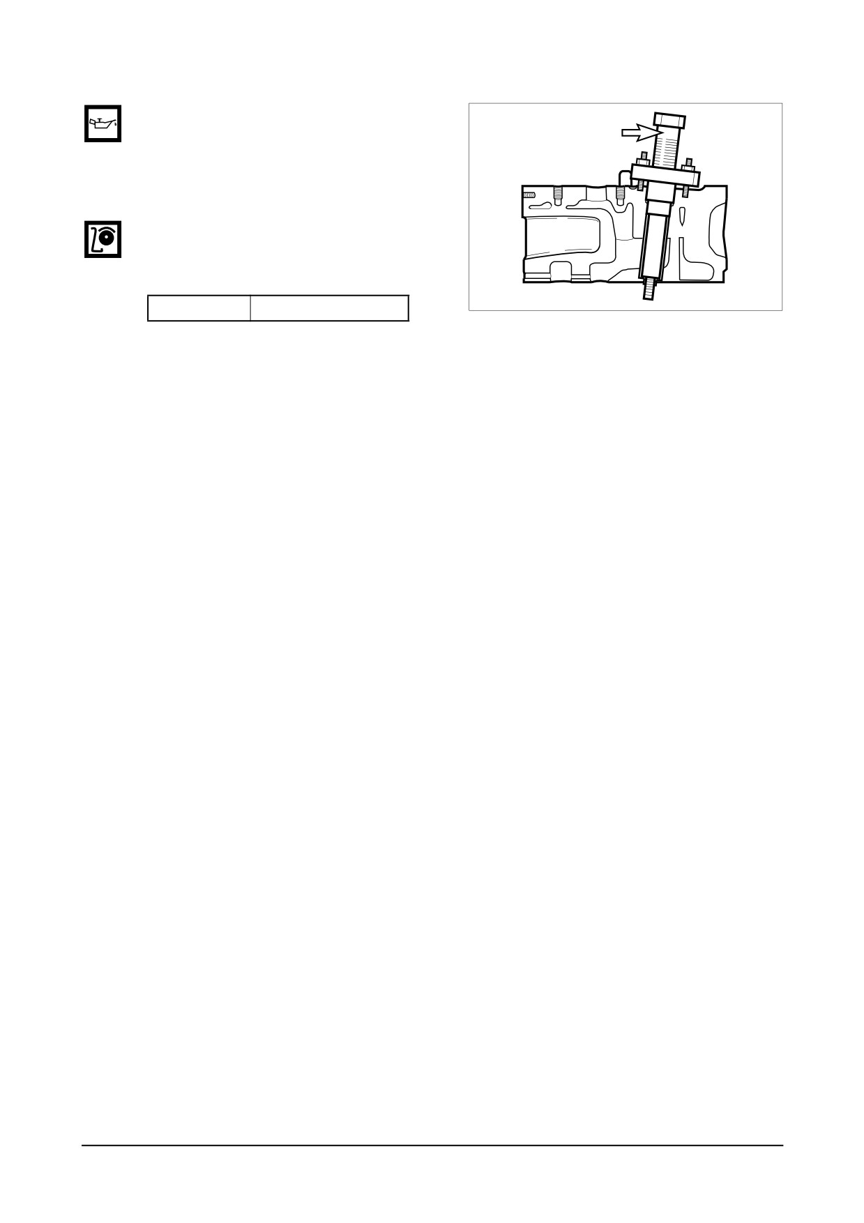
● Apply engine oil to an expander and
install it onto the special tool (guider).
Expander
● Tighten the bolts until the expander is
forced out of the cylinder head bot-
tom.
● After mounting the nozzle tube, make
a hydraulic test to check for water
leaks.
EAMD099I
Test pressure
2 kg/cm2
-
102 -
Disassembly and Reassembly of Major Components
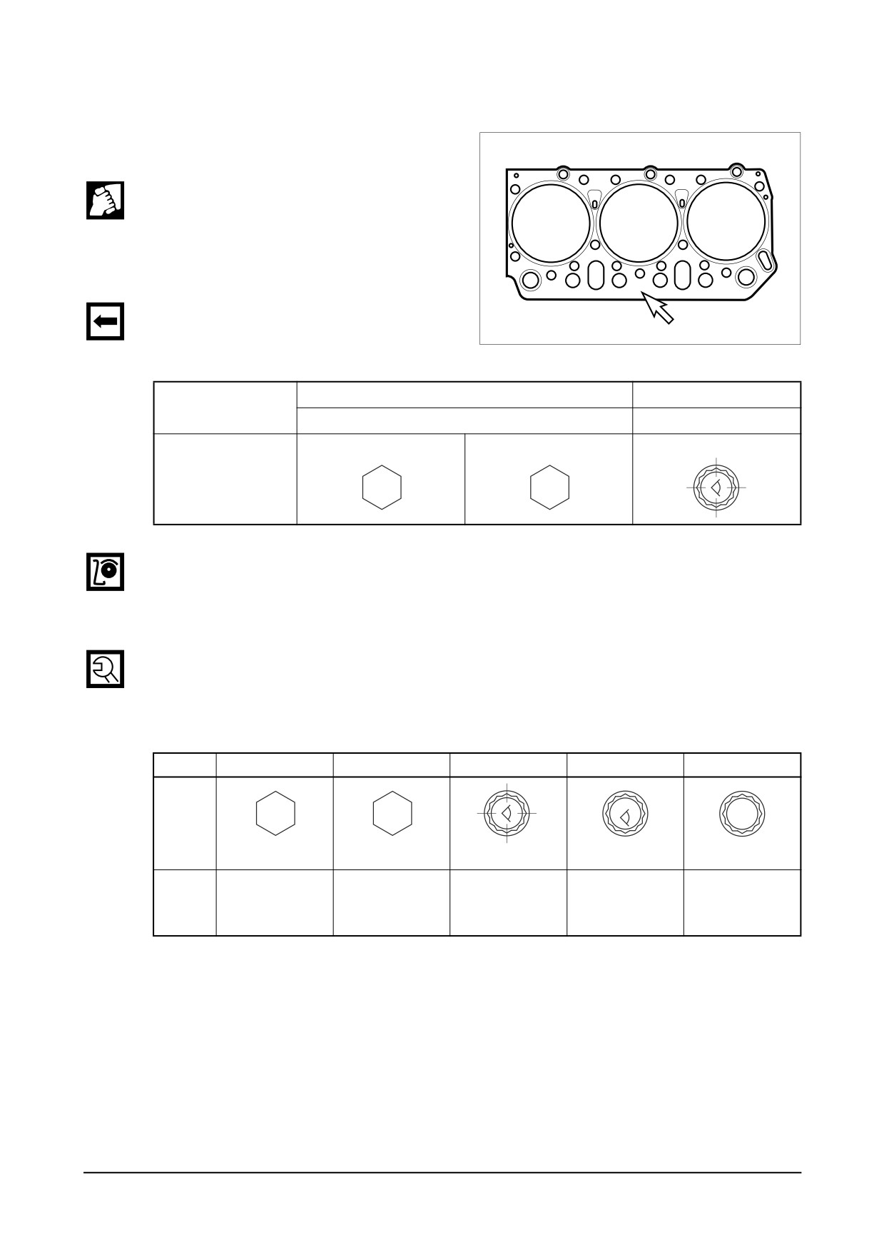
9.3.21. Cylinder head
● Install the injection nozzle fixing stud
bolts and water pipe fixing stud bolts.
● Clean the head bolt holes on the cyl-
inder block with compressed air to
remove foreign substances and thor-
oughly clean the gasket fitting face of
the cylinder block.
TOP
● Install head gasket, with 'TOP' mark
facing upward, on the cylinder block
EAMD101I
by aligning the holes with dowels.
Cylinder Head
Asbestos core type
Semi steel type
gasket
Rubber color : Black
Rubber color : Red
Use bolt
TY
TY
12.9T
10.9T
● Check the inside of combustion chamber for foreign substances, and carefully mount the cyl-
inder head assembly in the block by aligning the dowel pin with the dowel pin hole. Be care-
ful not to
damage the head gasket. If the dowel pin is not in alignment, lift the cylinder
head again and then remount it.
● Coat the head bolts with engine oil, then tighten them in proper sequence to the specified
torque.
<Cylinder Head Bolts>
Type1
Type2
Type3 (12.9T)
Type4 (12.9T)
Type5 (10.9T)
TY
TY
TY
DL08
Type
12.9T
10.9T
M14 x 1.5 x 153
M14 x 1.5 x 150
M14 x 1.5 x 153
M14 x 1.5 x 150
M14 x 1.5 x 150
1st : 6 kgm
1st :
6 kgm
1st :
7kgm
1st :
6 kgm
Tighten
24.5 kg.m
2nd : 180°
2nd : 90°+ 90°
2nd : 90°+ 90°
2nd : 90°+ 90°
torque
Finished : 150°
Finished : 30°
Finished : 90°
However, before tightening bolts, align the side face of 2 cylinder heads with parallel. They
should be adjusted in a straight line exactly.
Disassembly and Reassembly of Major Components - 103 -
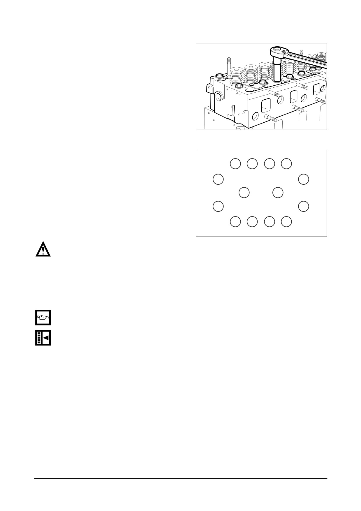
<Tightening order of bolts by steps>
(1) First stage
: Coat the bolts with
engine oil.
(2) Second stage
: Tighten
1
~
2
threads with hands.
(3) Third stage
: Tighten at about
6
kgm with a wrench.
(4) Fourth stage
: Tighten at rotating
angle method 90° with a wrench.
EAMD102I
(5) Fifth stage
: Tighten at rotating
angle method 90° with a wrench.
(6) Sixth stage
: Finally, tighten at
rotating angle method
90° with a
8
2
3
9
torque wrench .
12
13
Especially, all bolts are tightened
1
4
simultaneously in each step according
11
14
to above process as possible.
7
6
5
10
EAMD103I
NOTE :
Cylinder head bolts should be
replaced by new one after using two
or three times because of being
loosed as a result of its length too
extended. (Limit length 150mm)
● Coat the push rod with engine oil and
insert it into the push rod hole.
● Adjust the valve clearance as follow-
ing guide.
D
-
104 -
isassembly and Reassembly of Major Components
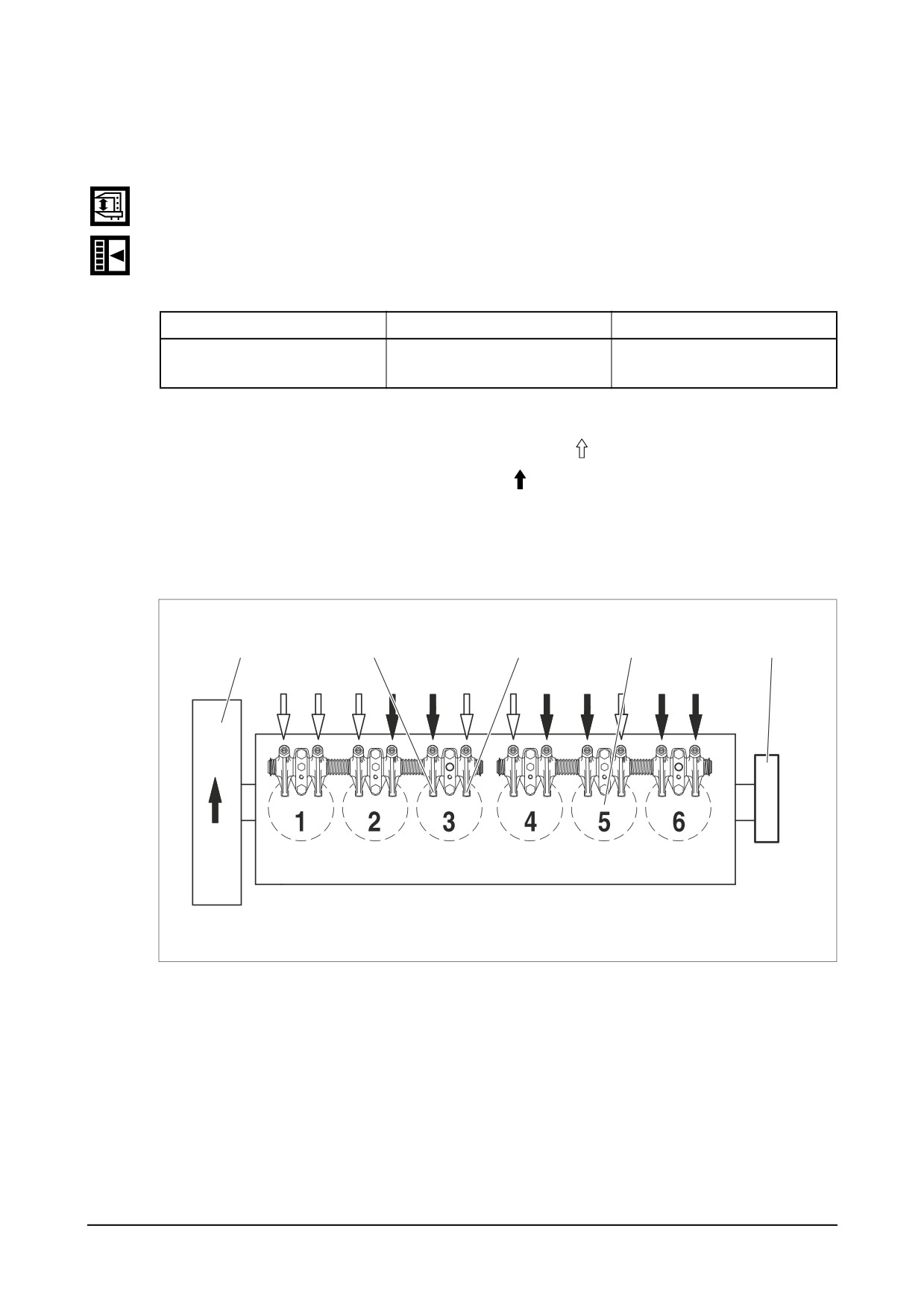
<Guide for valve clearance adjustment>
● After letting the #1 cylinder’s piston come at the compression top dead center by turning the
crankshaft, adjust the valve clearances.
● Loosen the lock nuts of rocker arm adjusting screws and push the feeler gauge of specified
value between a rocker arm and a valve stem and adjust the clearance with adjusting screw
respectively and then tighten with the lock nut.
● As for the valve clearance, adjust it when in cold, as follow.
(mm)
Model
Intake valve
Exhaust valve
DE12T
0.3
0.3
P126TI series / PU126TI
- By cranking the engine, let #6 cylinder’s valves overlap.
- In time, adjust the valve clearance corresponding to “
” of lower lists.
- Adjust the valve clearance corresponding to “
” of lower lists.
- After reinsuring the valve clearances, retighten if necessary.
● No. 1 Cylinder is located at the side where flywheel was installed.
Flywheel
Intake Valve
Exhaust Valve
Cylinder No.
Crank pulley
ED5OM005
Disassembly and Reassembly of Major Components - 105 -
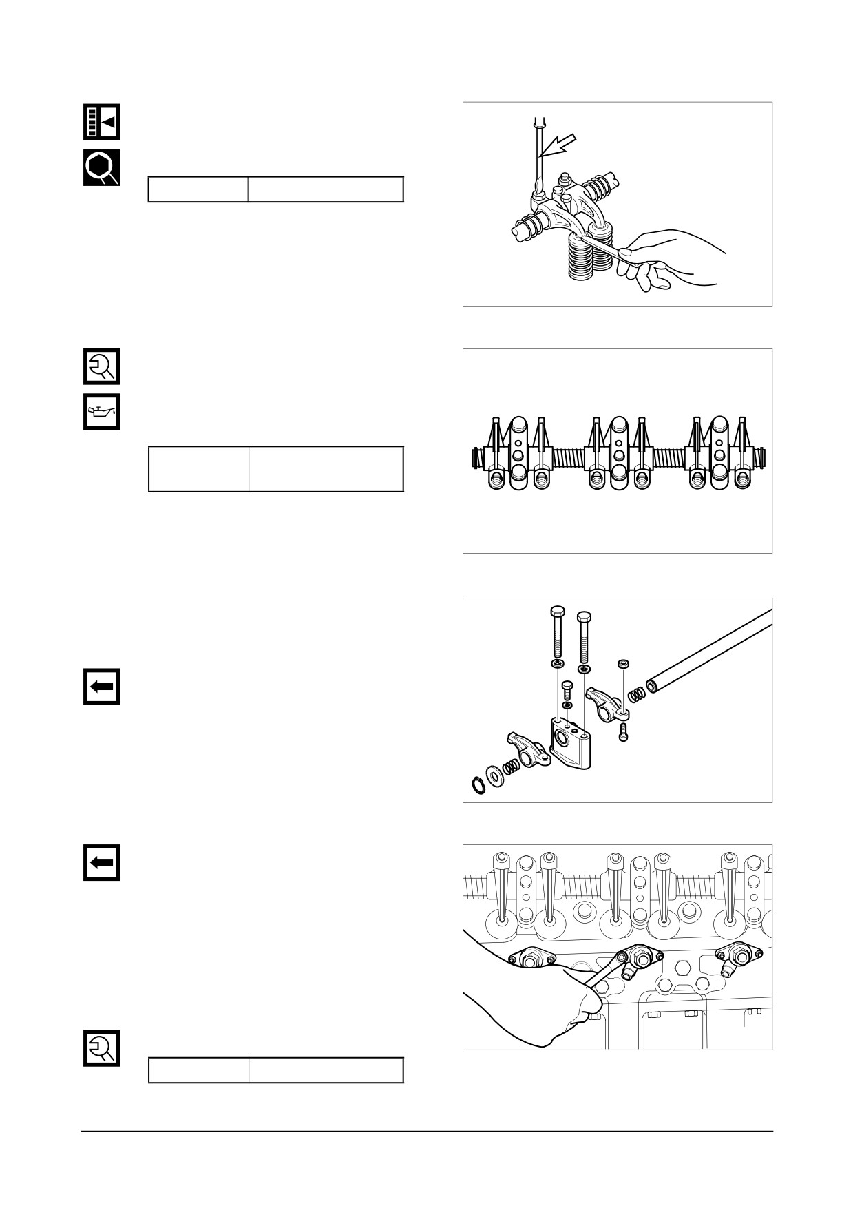
● Adjust valve clearance with a feeler
gauge and tighten the fixing nuts to
Valve clearance adjust
specified torque.
Torque
4.4 kgm
EA8M3007
9.3.22. Rocker arm assembly
● Apply lubricating oil to the rocker arm
bush and shaft, and assemble the
intermediate bracket with the rocker
arm using fixing bolts.
M10(x2) : 4.4 kgm
Torque
M8 : 2.2 kgm
● Semi-install valve clearance adjusting
bolts onto the rocker arm.
EAMD100I
● Install the spring, rocker arm, bracket,
rocker arm, spring, washer, and snap
ring in the described sequence.
● Install the rocker arm and bracket in
the same direction.
EA8M3008
9.3.23. Injection nozzle
● Install the dust seal with its round
portion facing downward.
● Mount a seal ring
(0.5 mm) on the
seal ring seating surface of the noz-
zle tube and assemble nozzle holder
assembly with the stud bolt with the
nozzle pipe installing
direction fac-
ing outward.
● Be sure to follow the specified torque.
EAMD105I
Torque
1.0 kgm
D
-
106 -
isassembly and Reassembly of Major Components
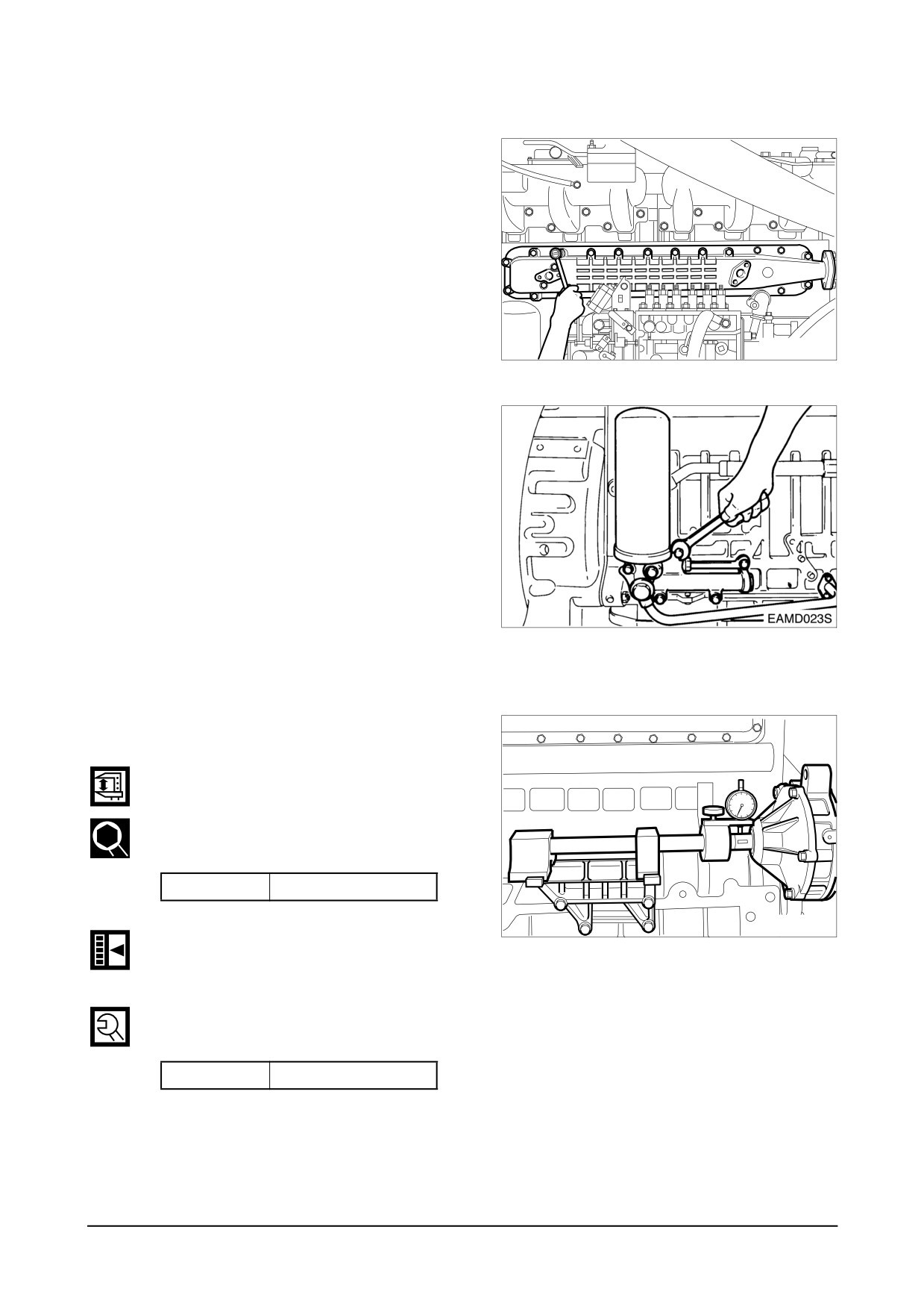
9.3.24. Oil cooler
● Install the oil cooler onto the oil
cooler cover.
● Carefully apply the gasket to prevent
oil leakage.
● Do not damage the gasket and install
the cover onto the cylinder block.
● Connect a connection pipe between
the water pump and oil cooler.
EAMD106I
9.3.25. Oil filter
● Install the oil filter onto the cylinder
block, and tighten the fixing bolts.
● With the hollow screw, assemble the
oil pipe connected between the oil
cooler and cylinder block.
● Install a connection pipe between the
oil cooler and oil filter.
● Install the oil cooler connecting pipe.
● Install packing and assemble the car-
tridge using a filter wrench.
9.3.26. Injection pump
● Install the injection pump bracket in
the cylinder block.
● After measuring the amount of run-
out with an alignment setting jig, dis-
assemble the bracket, adjust the
shims, then reassemble it.
Run out
0.2 or less
EAMD107I
● Mount the top/bottom adjusting shims
in the bracket and then mount the
fuel injection pump.
● Tighten the fixing bolts in a diagonal
sequence to specified torque.
Torque
4.4 kgm
Disassembly and Reassembly of Major Components - 107 -
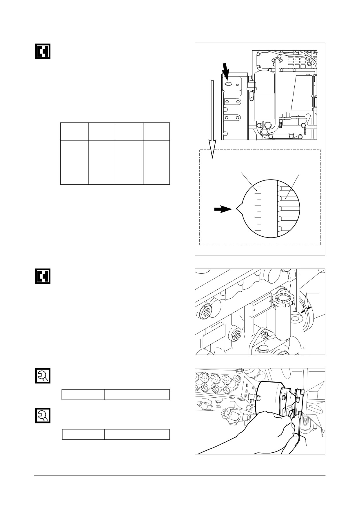
● Turn the flywheel until No. 1 piston is
Timing
placed in the
“OT" position of notch
Check hole
marks on the flywheel, and then turn
again the flywheel clockwise until
showing the notch mark of the right
figure corresponding to the injection
timing is aligned with the pointer ( ↓ )
on the flywheel housing.
DE12T /
P126TI /
PU126TI
P126TI-1
P126TI-II
Fuel
injection
timing
12°
16°
14°
Injection timing
Flywheel
(B.T.D.C
notch mark
ring gear
static)
EA8O6002
● Turn the timer until the notch mark of
the indicator plate attached to the fuel
Notch
injection pump is aligned with the
mark
notch mark of the timer.
EA9O5002
● Tighten the Coupling fixing bolts and
nuts to specified torque.
Torque
6.0 kgm
● Tighten the drive shaft connecting
flange fixing bolts to specified torque.
Torque
7.5 ~ 8.5 kgm
● Install the oil delivery pipe and return
EAMD021I
pipe.
D
-
108 -
isassembly and Reassembly of Major Components
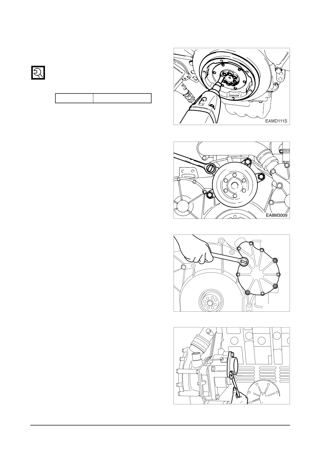
9.3.27. Vibration damper end pulley
● Install the vibration damper on the
crankshaft pulley.
● Install the crankshaft pulley assembly
on the crankshaft, then tighten the
bolts and thrust washers.
Torque
13.4 kgm
9.3.28. Fan drive pulley
● Install the fan drive pulley onto the
timing gear case cover.
9.3.29. Water pump
● Mount a new O-ring.
● Install the water pump drive pinion
over the PTO (power take-off) spline.
● Connect water pipes and by-pass
pipe to the water pump.
● Connect a water pipe to the expan-
sion tank.
EAMD112I
9.3.30. Power take-off
● Assemble the power take-off sub
assembly.
EA8M3010
Disassembly and Reassembly of Major Components - 109 -
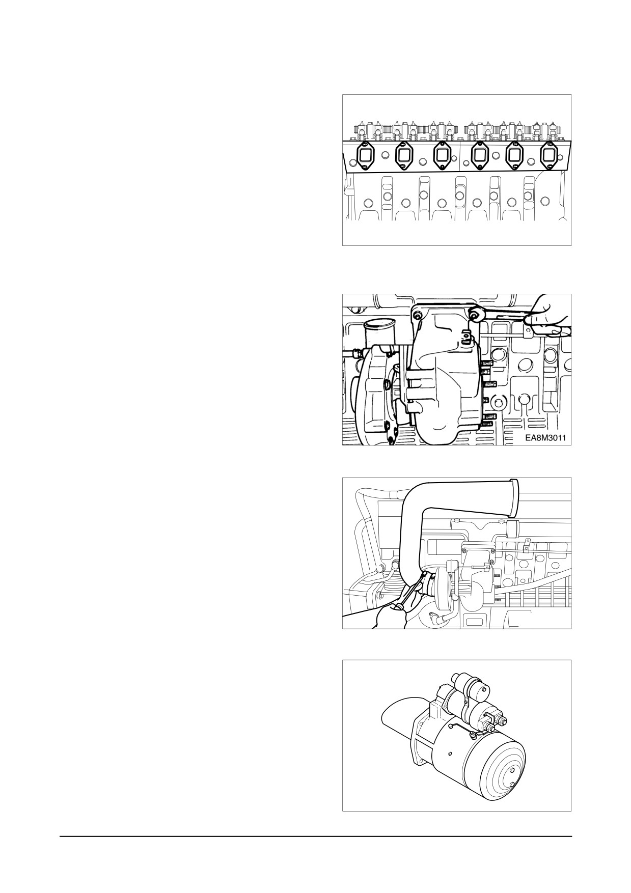
9.3.31. Exhaust manifold
● Install the exhaust manifold gasket over
the stud bolts by aligning the gasket
with the exhaust port on the cylinder
head so that the face and back of the
gasket can be positioned correctly.
● Semi-assemble the exhaust manifold
and install the heat resisting plate.
● First, install the nuts and then place
an additional nut on each of them to
EQM3096I
prevent looseness.
9.3.32. Turbocharger
● Fit a new gasket over the stud bolts
of the exhaust manifold before tight-
ening those turbocharger fixing bolts.
● Install the oil supply pipe and return
pipe.
● Semi-assemble the bracket to the
intake pipe, connect a rubber hose
between the turbocharger and intake
pipe using rubber hose, then assem-
ble the bracket completely.
EA8M3012
9.3.33. Starter
● Assemble the starter in position on
the flywheel housing.
ED5OM009
-
D
110 -
isassembly and Reassembly of Major Components
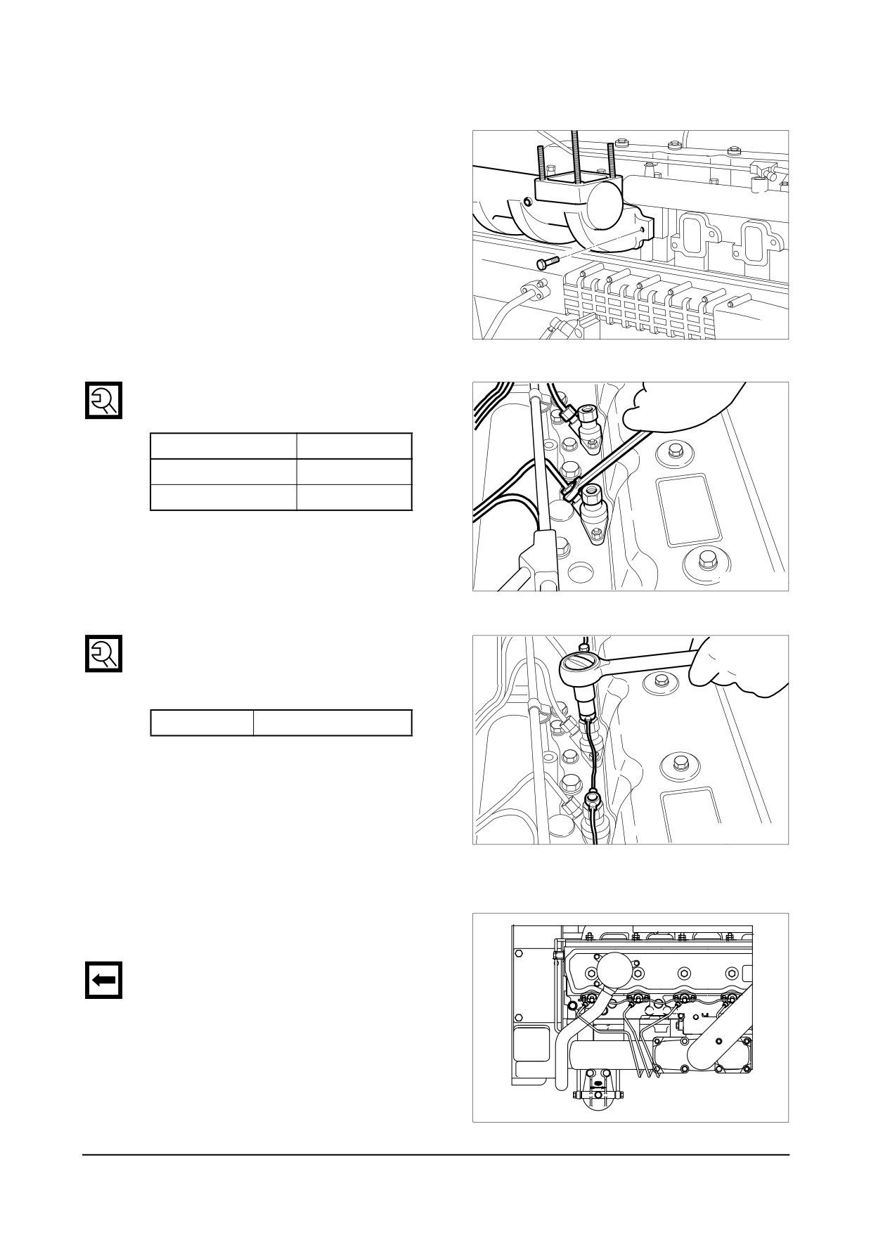
9.3.34. Intake manifold
● Fit a gasket on the intake manifold
before assembling the intake mani-
fold.
EQM3011I
9.3.35. Injection pipe & fuel return pipe
● Assemble the injection pipe according
to specified torque as blow
Nut size
Torque
Spanner Dia. 17 mm
3.0 kgm
Spanner Dia. 19 mm
4.0 kgm
EAMD011I
● Semi-assemble the nuts at both end of
the fuel injection pipe and tighten them
up one by one to specified torque.
Torque
1 ~ 1.5 kgm
● Tighten the hollow screws to assem-
ble the fuel return pipe.
● Assemble the fuel return hose on the
fuel injection pump.
EI6OM015
9.3.36. Fuel filter
● Assemble the fuel filter with the
intake manifold.
● Assemble the fuel feed hose accord-
ing to the direction of an arrow
impressed on the fuel filter head so
that fuel can be fed in the sequence
of FUEL FEED PUMP → FUEL FIL-
TER → FUEL INJECTION PUMP.
EI6OM016
Disassembly and Reassembly of Major Components - 111 -
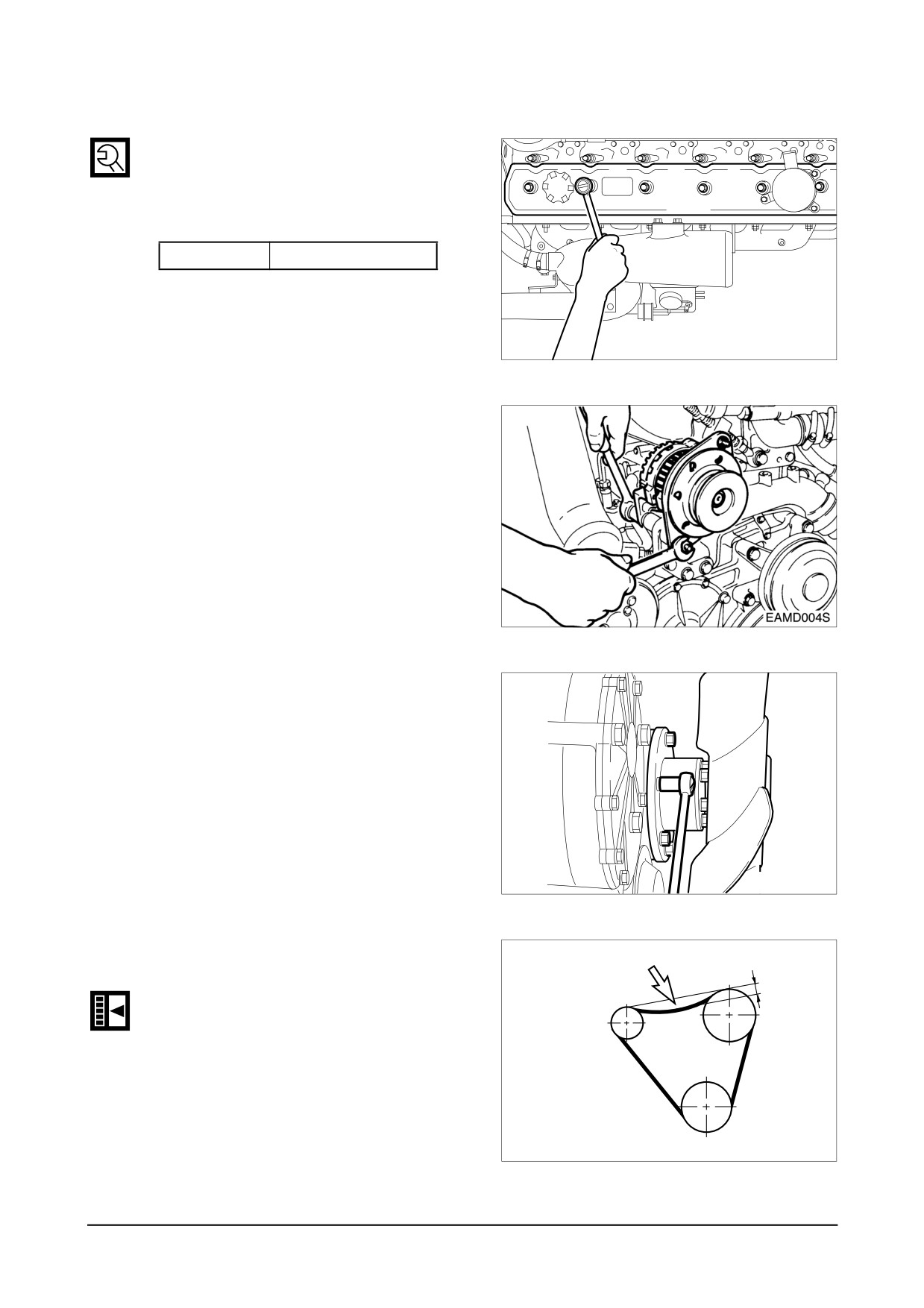
9.3.37. Cylinder head cover
● Assemble the cover packing with the
cover, install the cover on the head,
then tighten the fixing bolts in
sequence to specified torque.
Torque
2.5 kgm
● Assemble the breather hose with
PCV valve.
EI7OM011
9.3.38. Alternator
● Install the alternator mounting bracket.
● Install the alternator with fixing bolts
to the mounting bracket.
9.3.39. Cooling fan
● Install the cooling fan and flange,
then tighten the fixing boltd.
EQM3106I
9.3.40. V- belt
● Install the V-belt on the crank pulley,
Press here
alternator pulley and fan drive pulley.
15mm
● Adjust the V-belt tension using the
Fan
Alternator
tension adjusting bolt.
Pulley
Pulley
V-belt
Crank Pulley
EA8O3005
-
112 -
Disassembly and Reassembly of Major Components
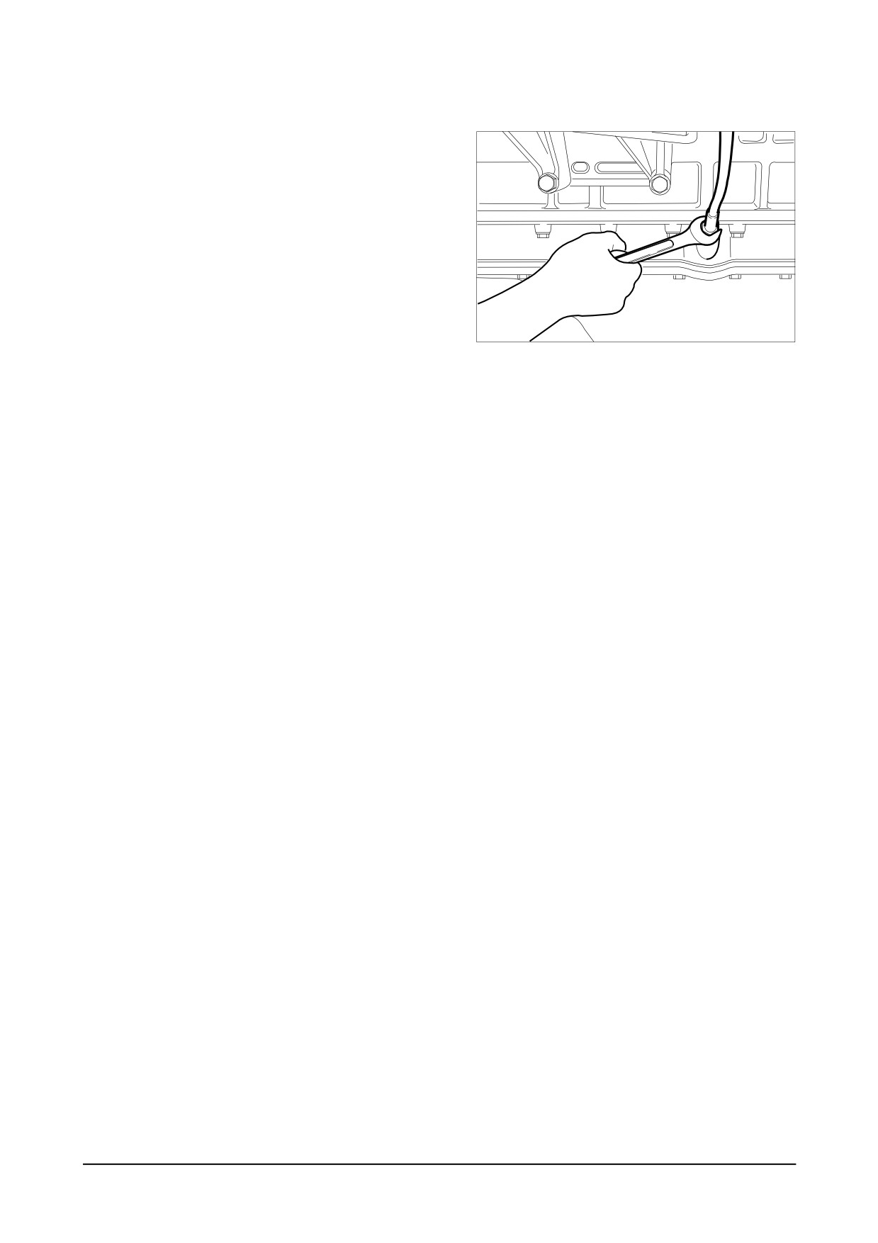
9.3.41. Oil level gauge
● Assemble the oil level gauge and
guide tube on the oil pan.
EQM3005I
9.4. Breaking-in
Refer to “Breaking-in” in chapter of “Commissioning and Operation”.
Disassembly and Reassembly of Major Components - 113 -
10. Maintenance of Major Components
10.1. Cooling System
10.1.1. General information
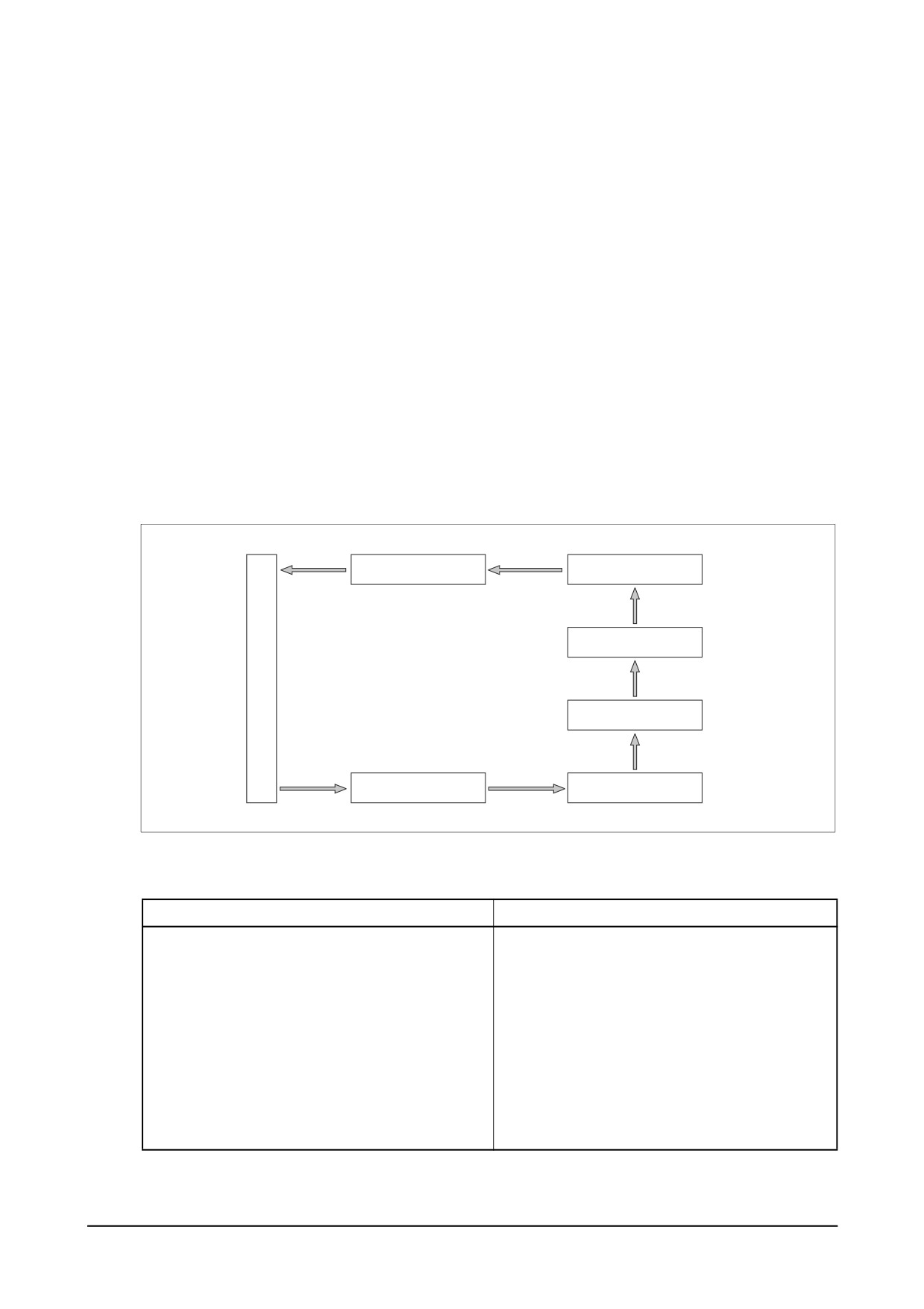
This engine is water-cooling type. Heat from the combustion chamber and engine oil heat are
cooled down by coolant and radiated to the outside, resulting in the normal operation of the
engine.
Looking into the cooling system, the water pumped up by the water pump circulates around the
oil cooler through the water pipe to absorb the oil heat, and then flows through the water jacket
of the cylinder block and water passage of the cylinder head to absorb the heat of the combus-
tion chamber.
The water absorbing the oil heat and combustion chamber heat goes on to the thermostat
through the water pipe, and circulates to the water pump if water temperature is lower than the
valve opening temperature on the thermostat, while circulating to the radiator at water tempera-
ture higher than the valve opening temperature. At the radiator, the heat absorbed in the cool-
ant is radiated to cool down and the coolant recirculates to the water pump.
Thermostart
Water pipe
R
a
Cylinder head
d
i
a
t
o
Cylinder block
r
Water pump
Oil cooler
ED5OM006
● Specification
Item
Specification
1. Water pump
Centrifugal type
type
Delivery
About 280 liter/min
Pumping speed
2,234 rpm
Pumping back pressure
760 mmHg
2. Thermostat
Operating temperature
71 ~ 85C / 83 ~ 95C
3. Cooling fan and belt
Fan diameter - Number of blades
൵755 - 7
Fan belt tension
15mm / deflection by thumb
-
114 -
Maintenance of Major Components
10.1.2. Water pump
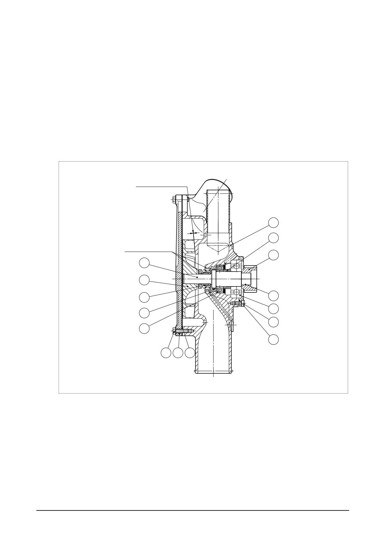
● Loosen the bolt (16) to disassemble the housing cover (15).
● Heat the impeller (6) slightly, then remove it using a puller jig.
● Remove the mechanical seal.
● Unscrew the socket bolt (12) and remove the shaft and bearing assembly from the housing.
● With a press, remove the spline shaft and bearing.
● Reverse the disassembly sequence for reassembly operation.
● Replace the oil seal (7) with a new one at reassembly.
● To reassemble the impeller, maintain a constant gap (0.3 ~ 0.6 mm) between the impeller
and pump housing using a feeler gauge.
Thickness 0.3 ~ 0.6
1
9
Par latex coating
11
4
6
5
13
10
7
12
8
11
16
15
14
ED5OM007
<Construction of water pump>
1. Water pump housing
8. Ball bearing
13. Spline shaft
4. Shaft
9. Spacer
14. Gasket
5. Mechanical seal
10. Ball bearing
15. Housing cover
6. Impeller
11. Bearing cover
16. Bolt
7. Oil seal
12. Socket bolt
Maintenance of Major Components
-
115 -
10.1.3. Thermostat
● General descriptions and main data
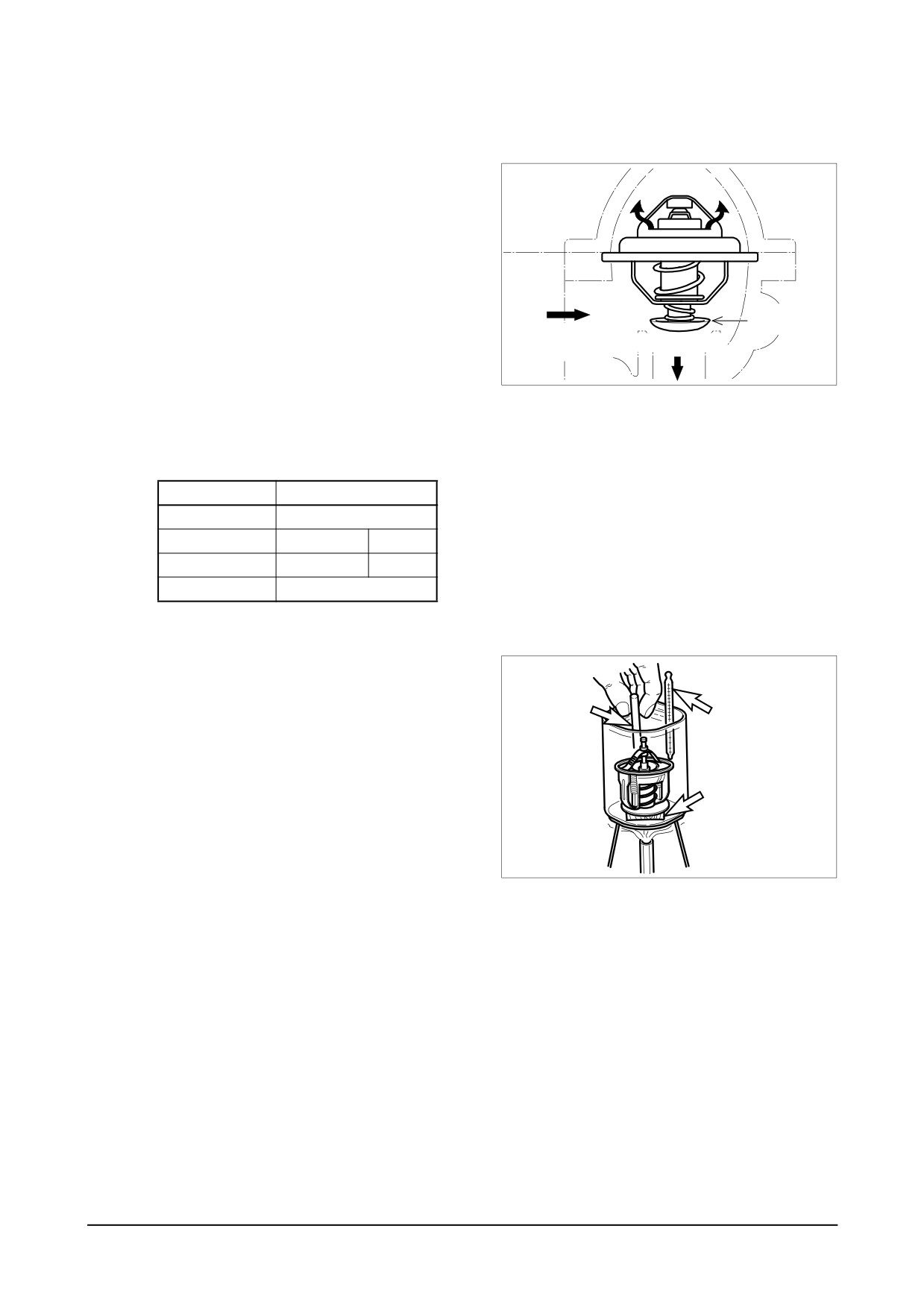
The thermostat maintains a constant tem-
To radiator
perature of coolant
(71 ~ 85C / 83 ~
95C) and improves thermal efficiency of
the engine by preventing heat loss.
Namely, when the temperature of coolant
is low, the thermostat valve is closed to
make the coolant bypass to directly enter
Bypass
valve
the water pump; when the coolant tem-
From cooling
To bypass tube
water pipe
perature rises to open wide the thermo-
EAMC002I
stat valve, the bypass circuit is closed
and the water passage to the radiator is
opened so that the coolant is forced to
flow into the radiator.
Item
Specifications
Type
Wax-pallet type
Open at
71C
83C
Open wide at
85C
85C
Valve lift
8 mm or more
● Inspecting
1) Check the wax pallet and spring
for damage.
2) Put the thermostat in a container of
Ruler
Thermometer
water, then heat the water slowly and
check temperature with a thermome-
ter. If the valve lift is 0.1 mm (starting
Woodplate
to open) at temperature of
71C /
83C and 8 mm or more (opening
wide) at temperature of 85C / 95C,
EFM2055I
the thermostat is normal.
● Replacing thermostat and precautions for handling
1) Precautions for handling
The wax pallet type thermostat does not react as quickly as bellows type one to a varia-
tion of temperature of coolant. Such relatively slow reaction is mainly due to the large
heat capacity of the wax pellet type thermostat. Therefore, to avoid a sharp rise of cool-
ant temperature, it is essential to idle the engine sufficiently before running it. In cold
weather, do not run the engine at overload or overspeed it immediately after starting off.
2) When draining out or replenishing coolant, do it slowly so that air is bled sufficiently from
the entire cooling system.
3) Replacing thermostat
If the thermostat is detected defective, retrace with a new one.
-
116 -
Maintenance of Major Components