DOOSAN Generator diesel engine DE12T, P126TI, P126TI-1, P126TI-II, PU126TI. Operation and Maintenance Manual - page 2
5.5. Fuel System
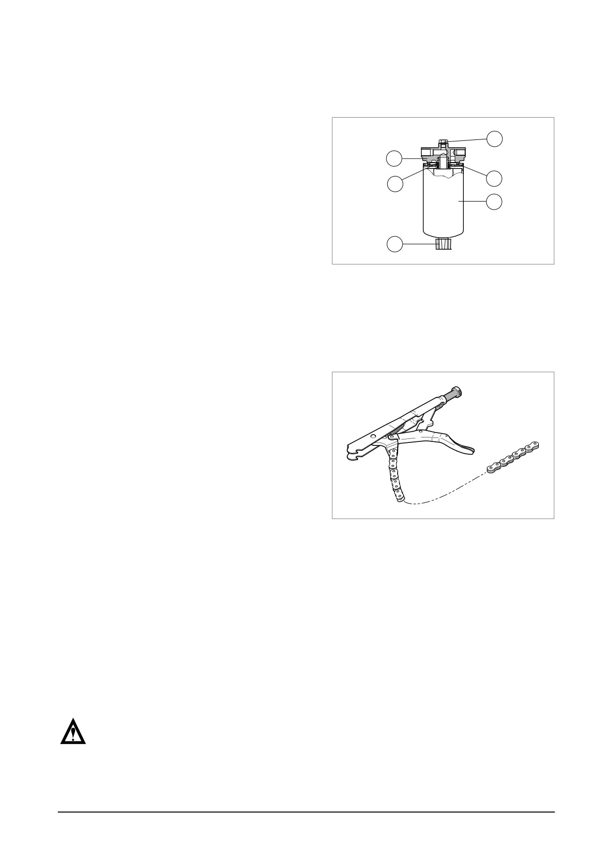
5.5.1. Fuel filter
● After every
200 hour of operation,
drain the water and sediment from
1
the fuel-water separator.
3
● Shut off the engine. Use your hand to
5
4
open the drain valve (6).
● Turn the valve counter clockwise
2
approximately 2 ~ 3 turns until draining
occurs. Drain the filter sump of water
6
until close fuel is visible.
EA2O4009
● Turn the valve clockwise to close the
drain valve. Do not over tighten the
valve, overtightening can damage the
threads.
5.5.2. Replacement of fuel filter
● Clean the area around the fuel filter
head (3).
● Remove the fuel filter
(2) by turning it
counter-clockwise with filter wrench.
(Discard the used filter.)
● Remove the fuel filter thread adapter
seal ring (4).
● Use a clean lint free cloth to clean the
gasket surface of the fuel filter head (3).
EA7O5008
● Install the new thread adapter seal ring
(4) supplied with the new filter.
● Use clean oil to lubricate the filter seal
(5), and fill the new filter with clean fuel.
● Install the filter on the filter head (3).
● Tighten the filter until the gasket contacts
the filter head surface.
● Tighten the filter on additional one-half to
three-fourths of a turn with the filter
wrench, on as specified by the filter
manufacturer.
NOTE :
Mechanical over tightening of the
filter can distort the thread or
damage the filter element seal.
Maintenance and Care
-
37 -
5.5.3. Fuel system checks
Fill the tank with the recommended fuel. Keeping tanks full reduces water condensation and
helps keep fuel cool, which is important to engine performance.
Make sure fuel supply valves (if used) are open.
To insure prompt starting and even running, the fuel system must be primed with the fuel feed
pump manually before starting the engine the first time, or after a fuel filter change.
Refill at the end of each dayís operation to prevent condensation from contaminating the fuel.
Condensation formed in a partially filled tank promotes the growth of microbial organisms that
can clog fuel filters and restrict fuel flow.
If the engine is equipped with a fuel water separator, drain off any water that has accumulated.
Water in fuel can seriously affect engine performance and may cause engine damage. DOOSAN
recommends installation of a fuel water separator on generator units.
● Air removal of fuel system
The suction room of fuel injection pump has the function of air removal continuously during
the operation through a relief valve.
In case that the suction room lacks fuel at all, for instance, in case of new installation of
injection pump, after loosening the air removing screws of cartridge filter respectively,
remove the air by operating the manual pump of fuel supply pump until bubble will disap-
pear.
● Fuel supply pump
Every time of engine oil replacement, the fuel strainer installed at the fuel supply pump should
be removed and cleaned.
5.5.4. Fuel Contamination and water trap
In the generator environment, the most likely fuel contaminants are water and microbial growth
(black “slime”). Generally, this type of contamination is the result of poor fuel handling practices.
Black ìslimeî requires water in the fuel to form and grow, so the best prevention is to keep
water content to a minimum in storage tanks.
If diesel fuel which contains moisture is used the injection system and the cylinder liners / pis-
tons will be damaged. This can be prevented to same extent by filling the tank as soon as the
engine is switched off while the fuel tank is still warm (formation of condensation is prevented).
Drain moisture from storage tanks regularly. Installation of a water trap upstream of the fuel filter
is also advisable.
NOTE :
A galvanized steel tank should never be used for fuel storage, because the fuel oil
reacts chemically with the zinc coating to form powdery flakes which can quickly clog
the fuel filters and damage the fuel pump and injection nozzles.
-
38 -
Maintenance and Care
5.5.5. Priming pump strainer cleaning
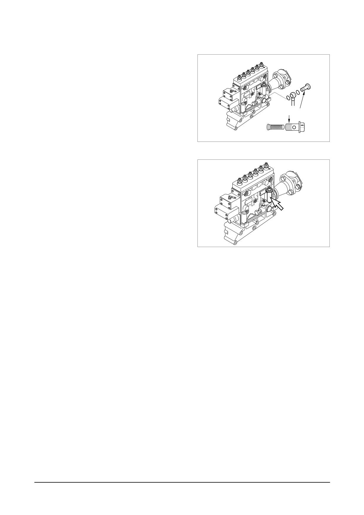
Clean the priming pump strainer every
200
operation hours.
The strainer is incorporated in the priming
pump inlet side joint bolt.
Clean the strainer with the compressed
air and rinse it in the fuel oil.
Strainer(Inner)
EA7O5009
5.5.6. Bleeding the fuel system
Whenever fuel filter is changed or the
engine is stopped by cause of the fuel
lack, the air of fuel line must be removed
as follows.
Bleed the fuel by manually operating the
priming pump with fuel filter outlet joint
Priming pump
bolt and injection pump bleeder screw
loosened.
● Press the feed pump cap repetitively
EA9O4005
until the fuel without bubbles overflows
from the bleeding plug screw.
● After the whole air is pulled out, close
the plug screws of the filter and the
pump.
● Confirm the resistance of fuel delivery
by
repetition pressing of the feed
pump cap, Pressure and turn the prim-
ing pump cap simultaneously to close
it.
5.5.7. Injection pump
● Check the fuel injection pump housing for cracks or breaks, and replace if damaged.
● Check and see if the lead seal for idling control and speed control levers have not been
removed.
● No alterations must be made to the injection pump. If the lead seal is damaged the warranty
on the engine will become null and void.
● We strongly recommended that any faults developing in the injection pump should be taken
care of by authorized specialist personnel.
Maintenance and Care
-
39 -
5.6. Injection Nozzle Maintenance (by authorized specialist personnel)
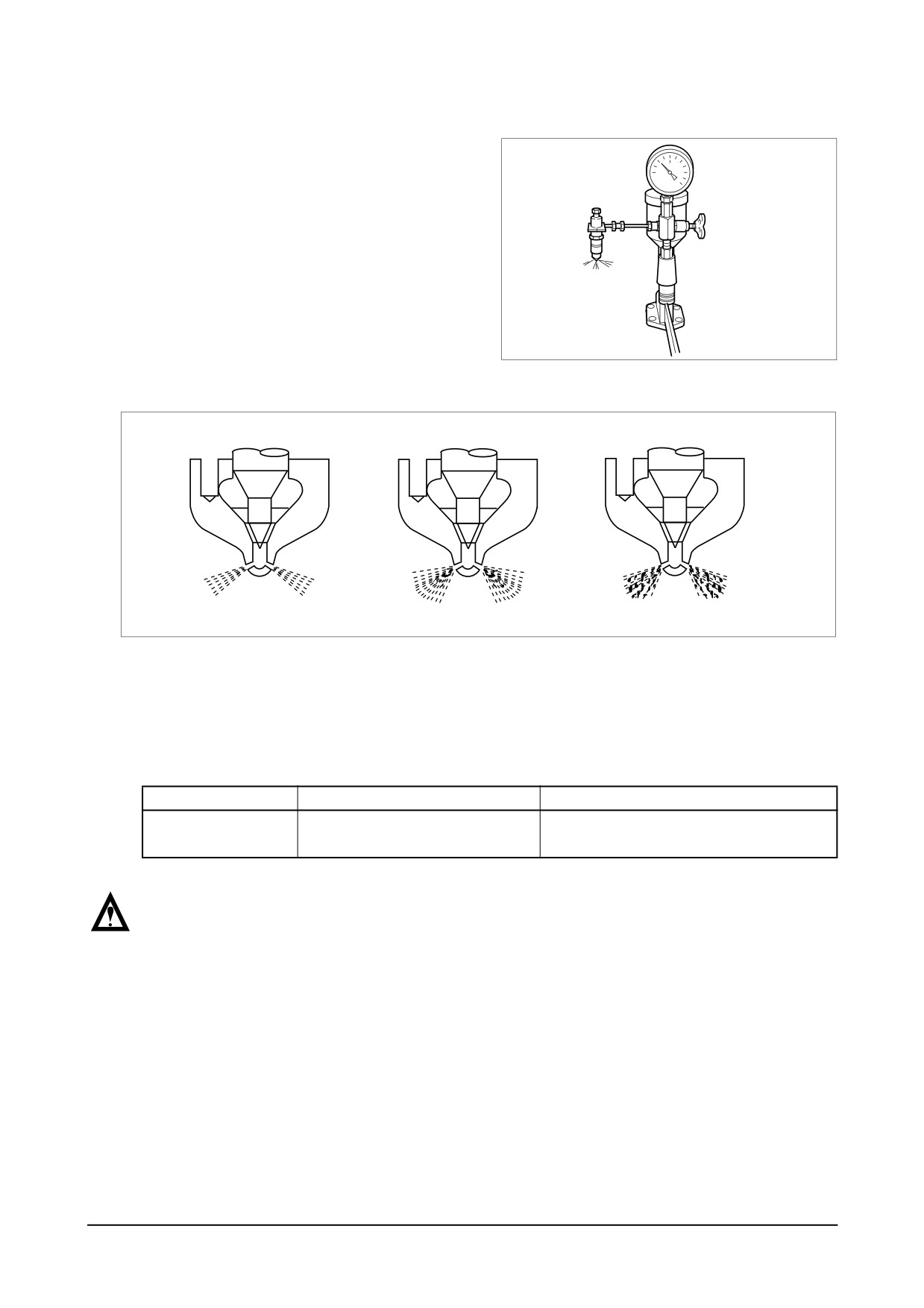
The injectors are designed to spray the
fuel delivered by the injection pump directly
into the spherical combustion chamber in
the piston crown. The injector consists of
the nozzle and the nozzle holder.
A copper seal fitted to the injector ensures
gas-tight seating and good heat dissipation.
The opening pressure of the nozzle is
adjusted by means of shims at the com-
EA0M3003
pression spring.
EFM1006I
● Install a nozzle to a nozzle tester.
● Check injection pressure, and adjust the nozzle using the adjusting shim if the pressure does
not meet the specified limit.
● Check nozzle spray patterns and replace if damaged.
DE12T
P126TI / P126TI-1 / P126TI-II / PU126TI
1st : 160kg/cm2
Opening pressure
220kg/cm2
2nd : 220kg/cm2
NOTE :
A galvanized steel tank should never be used for fuel storage, because the fuel oil
reacts chemically with the zinc coating to form powdery flakes which can quickly clog
the fuel filters and damage the fuel pump and injection nozzles.
● When mounting the pipes to the engine take care of good fitness.
● Do not bend pipes to permanent deformation (not for replacing the nozzles either).
● Do not mount any heavily bent pipes.
● Avoid bending the pipes at the ends by more than 2 to 3 degrees.
In case of faults in the injection system which might have resulted in excessive operating pres-
sures, not only the failed part but also the injection line has to be replaced.
-
40 -
Maintenance and Care
5.7. Turbocharger
5.7.1. Maintenance (by authorized specialist personnel)
The turbochargers do not call for any specific maintenance.
The only points to be observed are the oil pipes which should be checked at every oil change for leak-
age and restrictions. The air cleaners should be carefully serviced.
Furthermore, a regular check should be kept on charge air exhaust gas pipes. Any leakages should be
attended to at once because they are liable to cause overheating of the engine.
When operating in highly dust or oil-laden atmospheres, cleaning of the air impeller may be necessary
from time to time. To this end, remove compressor casing (Caution : Do not skew it!) and clean in a
non-acid solvent, if necessary using a plastic scraper.
If the air compressor should be badly fouled, it is recommended that the wheel be allowed to soak in a ves-
sel with solvent and to clean it then with a stiff brush. In doing so, take care to see that only the compressor
wheel is immersed and that the turbocharger is supported on the bearing casing and not on the wheel.
5.7.2. Special hints
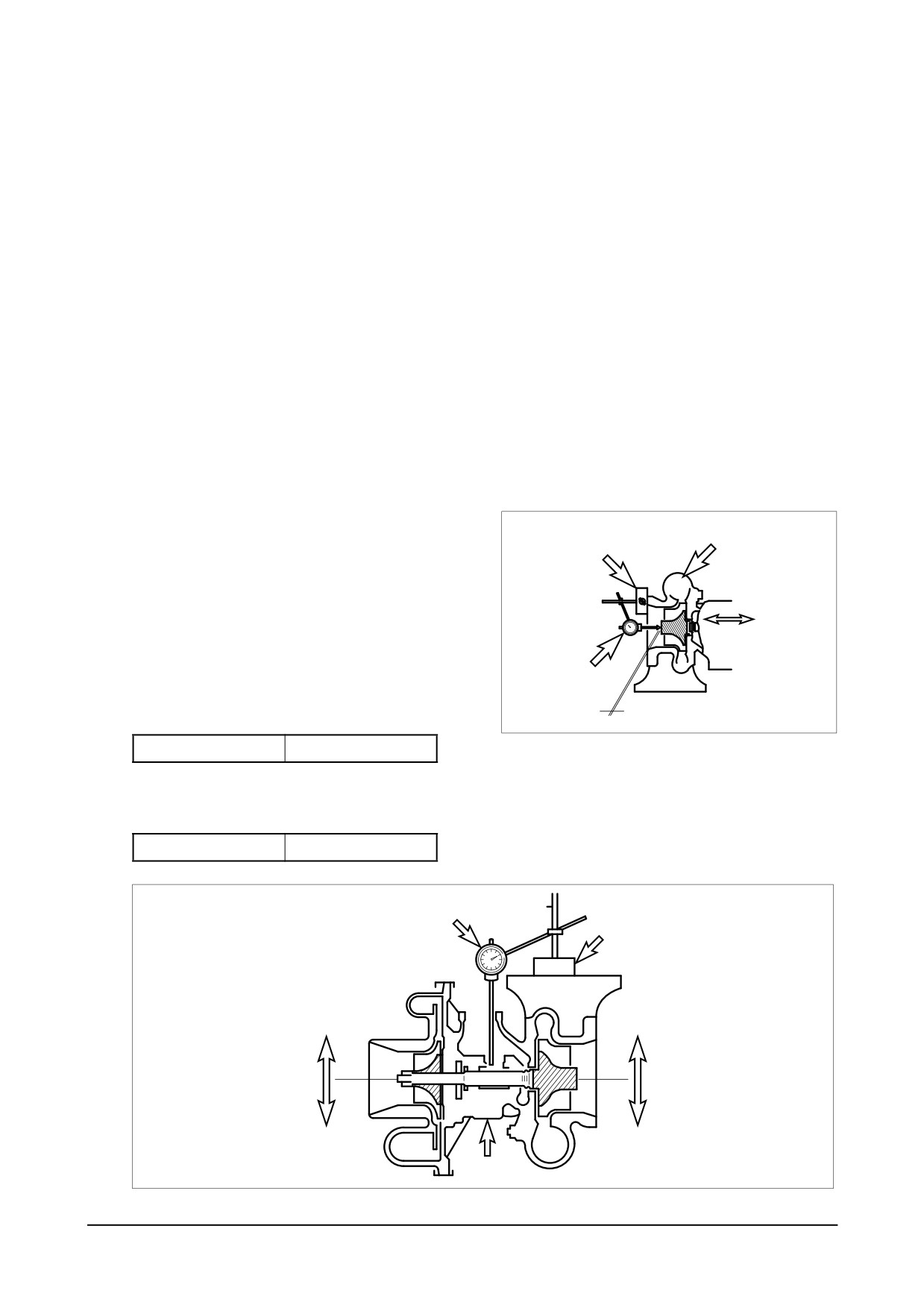
It is recommended that the radial and axial
Turbine wheel chamber
clearances of the rotor be checked after
Magnetic vise
every 3,000 hours operation.
This precaution will enable any wear of the
Measuring of axial clearance bearings to be
Move the turbine
detected in good time before serious damage
shaft to axial
direction
is caused to the rotor and bearings.
Dial gauge
<Measuring rotor axial clearance>
Wear limit : 0.20mm
(m m )
EA4M2017
Axial clearance
0.2
<Measuring radial clearance>
(m m )
Radial clearance
0.65
Dial gauge
Magnetic vise
Radial play
Move the turbine shaft
Limit of wear : 0.57mm
in both directions
simultaneously
Oil inlet
EA4M2018
Maintenance and Care
-
41 -
6. Checking and Setting
6.1. Adjustment of Valve Clearance
6.1.1. General information
The valve clearances are to be adjusted at the times of the following situations.
● After initial 50 hour’s operation.
● When the engine is overhauled and the cylinder heads are disassembled.
● When severe noise comes from valve train.
● When the engine is not normally operated, even though there is no trouble in the fuel system.
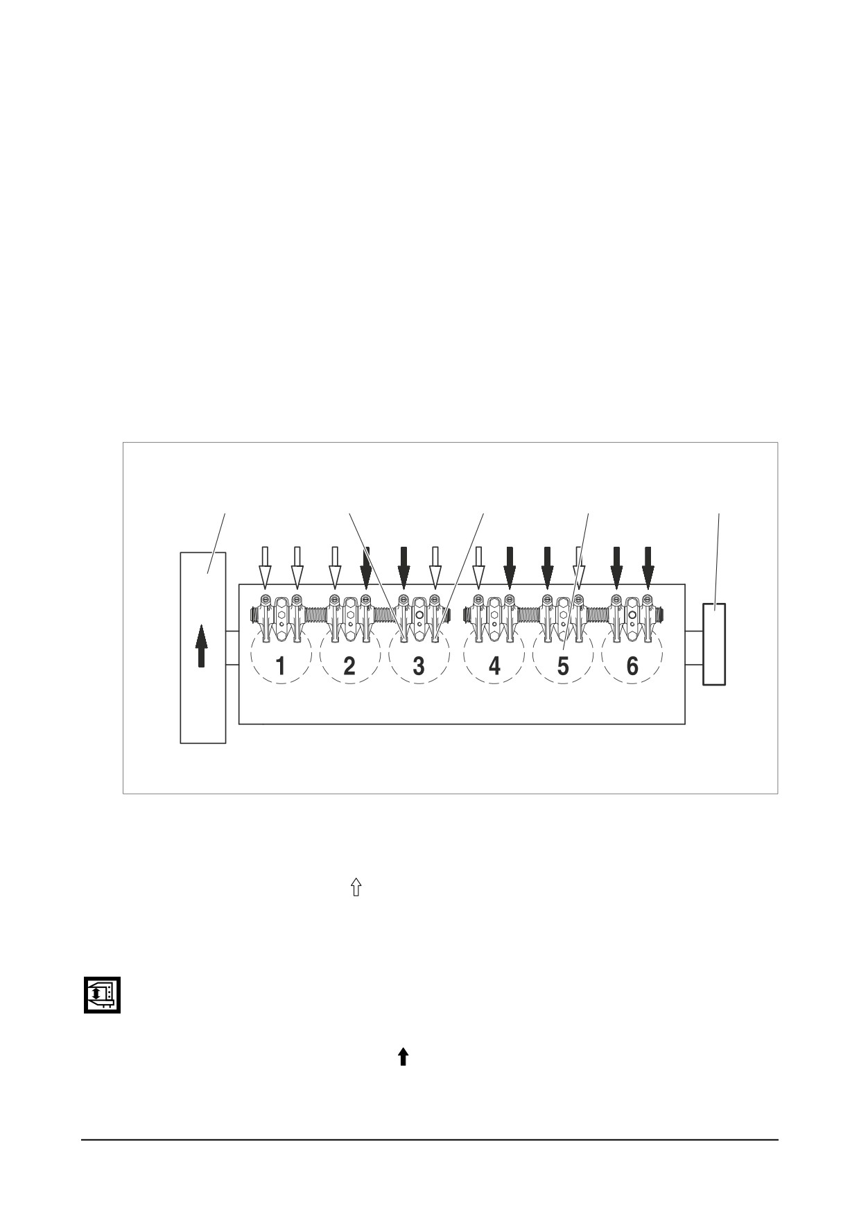
6.1.2. Adjusting order of the valve clearance
● Cylinder No. 1 begins from the rear side where the flywheel is mounted but cylinder No. 6
begins from the front side of the engine on the contrary.
Flywheel
Intake Valve
Exhaust Valve
Cylinder No.
Crank pulley
ED5OM005
Step 1 :
● After letting the cylinder No.6 in the overlap TDC position by turning the crankshaft, adjust
the valves corresponding to " " of following figure. At this time cylinder No. 1 should be at
the ignition TDC position (O.T).
Step 2 :
● After adjusting upper valves turn the crank pulley
360° to adjust the other valve clearance
until the cylinder No. 1 comes to overlap TDC position.
At this time cylinder No. 6 should be at the ignition TDC position (O.T).
● Adjust the valves corresponding to " " in upper figure.
After reconfirming the valve clearances, retighten it if necessary.
-
42 -
Checking and Setting
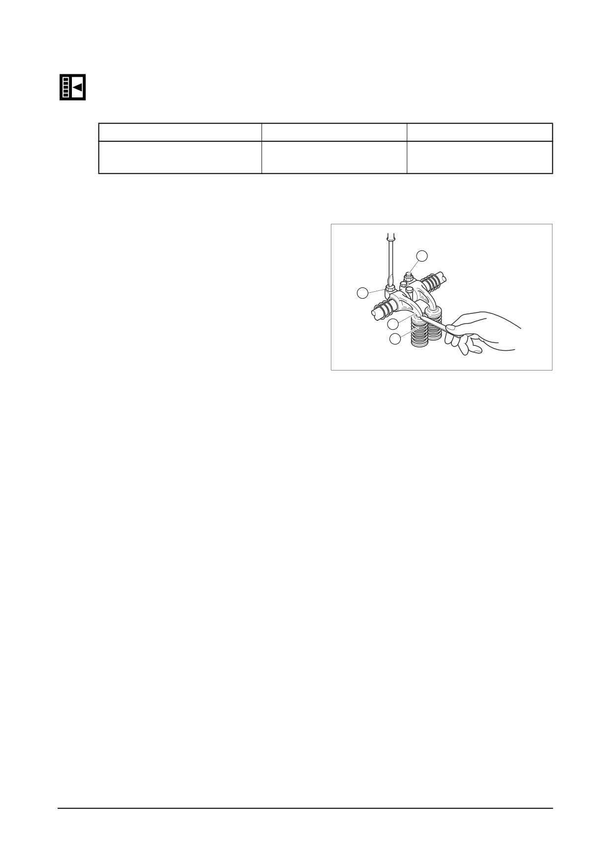
● Loosen the lock nuts of the rocker arm adjusting screws and push the specified feeler gauge
and adjust the valve clearance with adjusting screw respectively.
(mm)
Model
Intake Valve
Exhaust Valve
DE12T / P126TI / P126TI-1 /
0.3
0.3
P126TI-II / PU126TI
6.1.3. Method of adjusting the valve clearance
1) Loosen the lock-nuts
(1) using a ring
spanner.
4
2) Insert a thickness gauge of
0.3mm
between valve stem
(2) and rocker
arm (3).
1
3) Turn the adjusting bolts
(4) using a
3
screw driver until the gauge can be
2
pulled out with some restriction.
4) After the adjustment fix the adjusting
EAOO4014
bolt not to rotate and tighten the lock-
nut at the same time.
5) Measure the clearance one more time
and if necessary adjust again.
Checking and Setting
-
43 -
6.2. Adjustment of Injection Timing
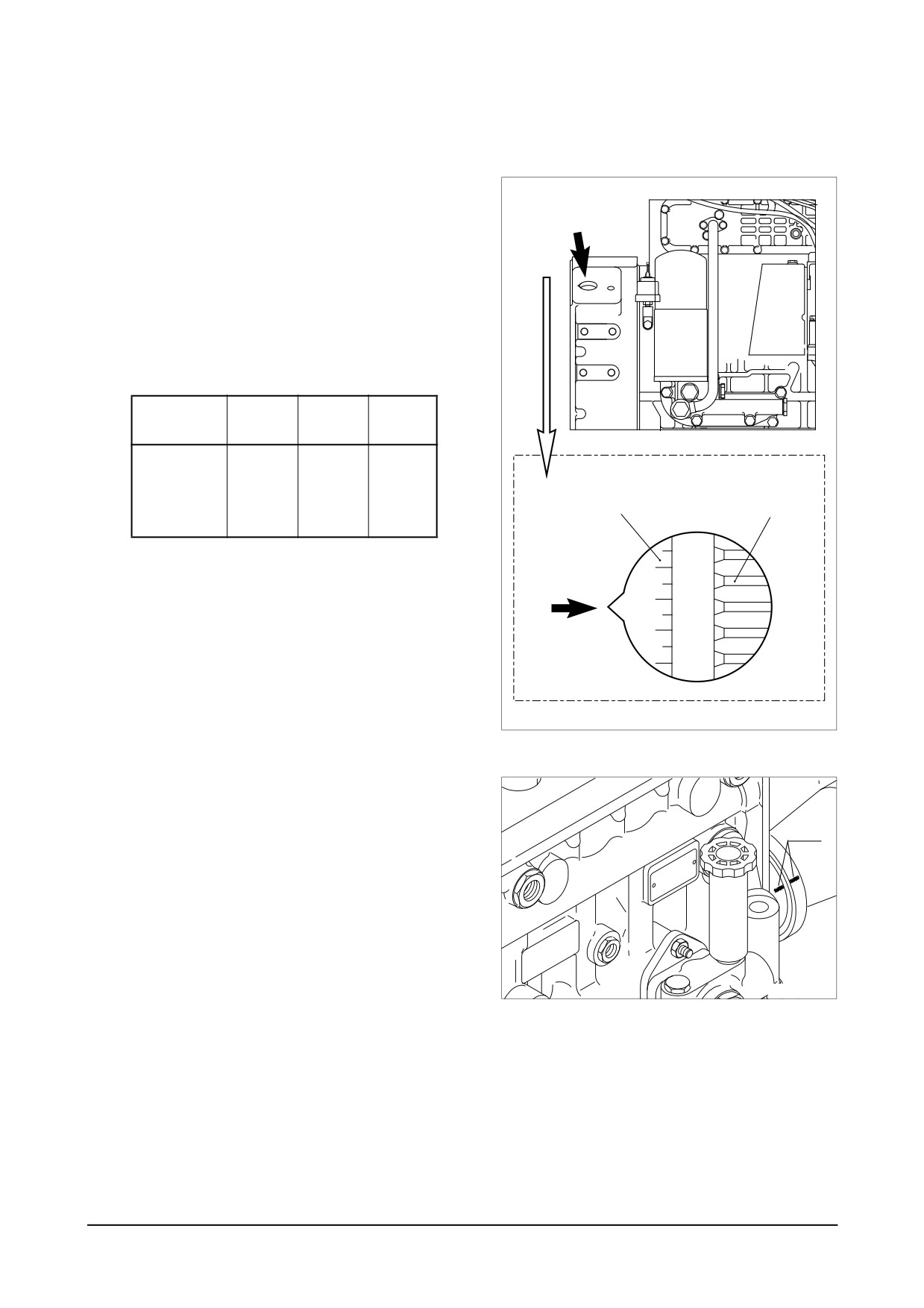
6.2.1. Method of adjusting injection timing
● Turn the flywheel until No. 1 piston is
placed in the
“OT” position of notch
Timing
Check hole
marks on the flywheel, and then turn
again the flywheel clockwise until
showing the notch mark of the right
figure corresponding to the injection
timing is aligned with the pointer
(↓)
on the flywheel housing.
DE12T /
P126TI /
PU126TI
P126TI-1
P126TI-II
Fuel injection
timing
12°
16°
14°
Injection timing
Flywheel
(B.T.D.C
notch mark
ring gear
static)
EA8O6002
● Turn the timer until the notch mark of
the indicator plate attached to the fuel
Notch
injection pump is aligned with the
mark
notch mark of the timer.
EA9O5002
-
44 -
Checking and Setting
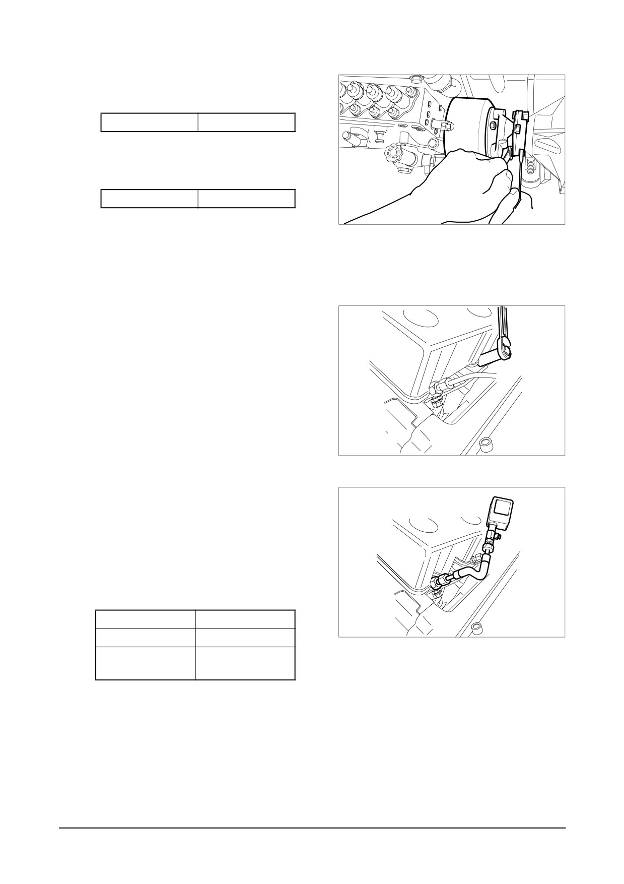
● Tighten the coupling fixing bolts and
nuts to specified torque.
Torque
6.0 kgm
● Tighten the drive shaft connecting
flange fixing bolts to specified torque.
Torque
7.5 ~ 8.5 kgm
EAMD021I
● Install the oil delivery pipe and return
pipe.
6.3. Cylinder Compression Pressure
1) Stop the engine after warming it up,
then remove the nozzle assemblies.
EA9O5003
2) Install a special tool
(gauge adapter) in
nozzle holder hole and connect the
compression
pressure gauge to the
adapter.
3) Cut off fuel circulation, rotate the starter,
then measure compression pressure of
each cylinder.
Standard value
25 ~ 28 kg/cm2
EA9O5004
Limit
24 kg/cm2 or less
Difference between
Within ± 10%
each cylinder
- Testing conditions : at water tempera-
ture of
20C and speed of
200 rpm
(10 turns)
Checking and Setting
-
45 -
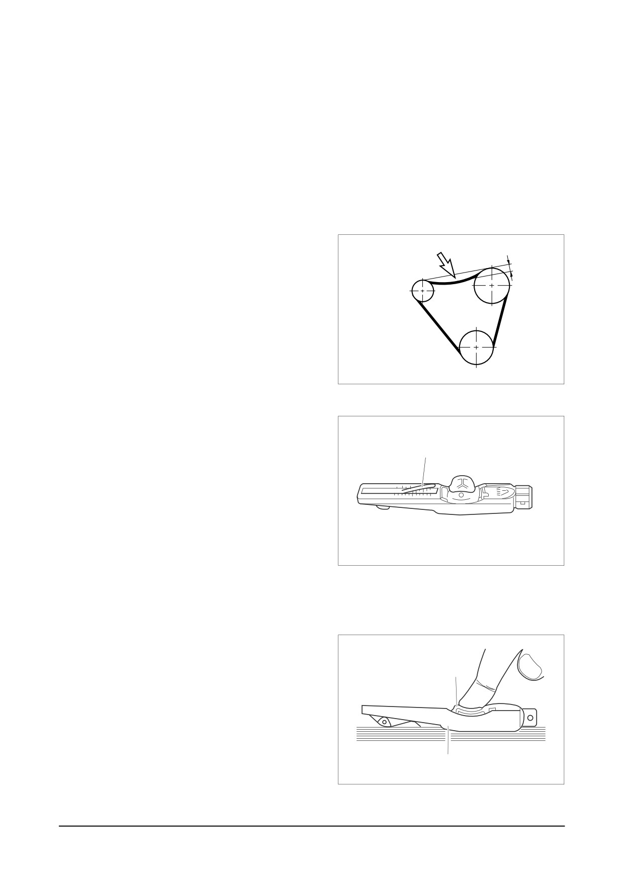
6.4. V-belts
The tension of the V-belts should be checked after every 2,000 hours of operation.
1)
Change the V-belts if necessary
If in the case of a multiple belt drive, wear or differing tensions are found, always replace the
complete set of belts.
2)
Checking condition
Check V-belts for cracks, oil, overheating and wear.
3)
Testing by hand
The tension is correct if the V-belts can
Press here
be pressed in by about the thickness of
15mm
the V-belt.
(no more midway between
Alternator
Fan
the belt pulleys)
Pulley
Pulley
A more precise check of the V-belt ten-
sion is possible only by using a V-belt
V-belt
tension tester.
Crank Pulley
EA8O3005
4)
Measuring tension
(1)
Lower indicator arm
(1) into the
scale.
(1)
● Apply tester to belt at a point mid-
way between two pulleys so that
edge of contact surface
(2) is
flush with the
V- belt.
● Slowly depress pad
(3) until the
spring can be heard to disengage.
This will cause the indicator to move
EA6O6011
upwards.
If pressure is maintained after the
spring has disengaged a false
reading will be obtained!
(2)
Reading of tension
● Read of the tensioning force of
(3)
the belt at the point where the top
surface of the indicator arm
(1)
intersects with the scale.
● Before taking readings make
ensure that the indicator arm
remains in its position.
(2)
EA6O6012
-
46 -
Checking and Setting
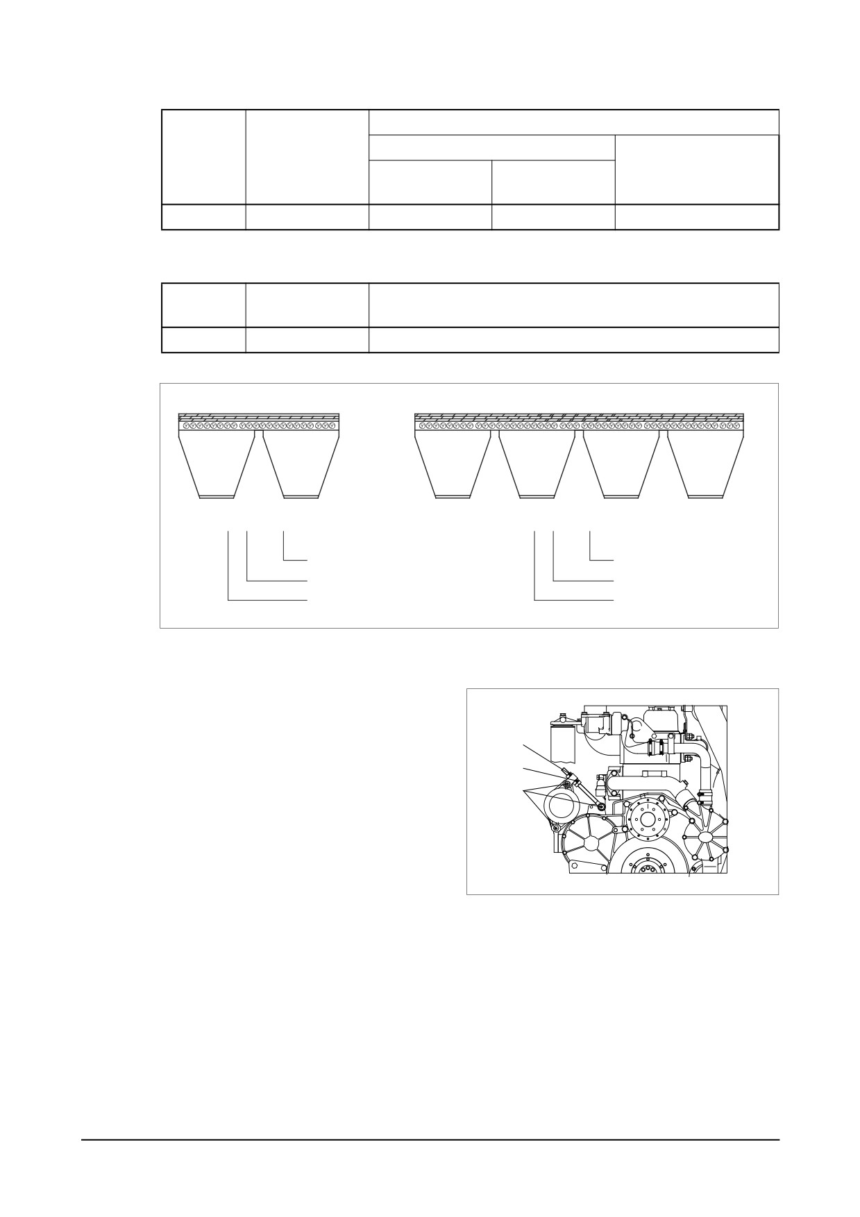
Tensioning forces on the tester
new installation
Type
Drive belt width
When servicing after
After 10 min.
Installation
long running time
running time
A
11.8 mm
55 kg
50 kg
45 kg
* V-belt of raw edge cogged type
When servicing after
Type
new installation
long running time
3V
45 kgf
41 kg
3V 2 - 0000
3V 4 - 0000
Belt length
Belt length
No. of belt rib
No. of belt rib
Belt type
Belt type
EF8OM084
5) Tensioning and changing V-belt
● Remove fixing bolts. (1)
● Remove lock nut. (2)
● Adjust nut (3) until V-belts have cor-
(2)
rect tensions.
(3)
● Retighten lock nut and fixing bolts.
(1)
EA8O6004
Checking and Setting
-
47 -
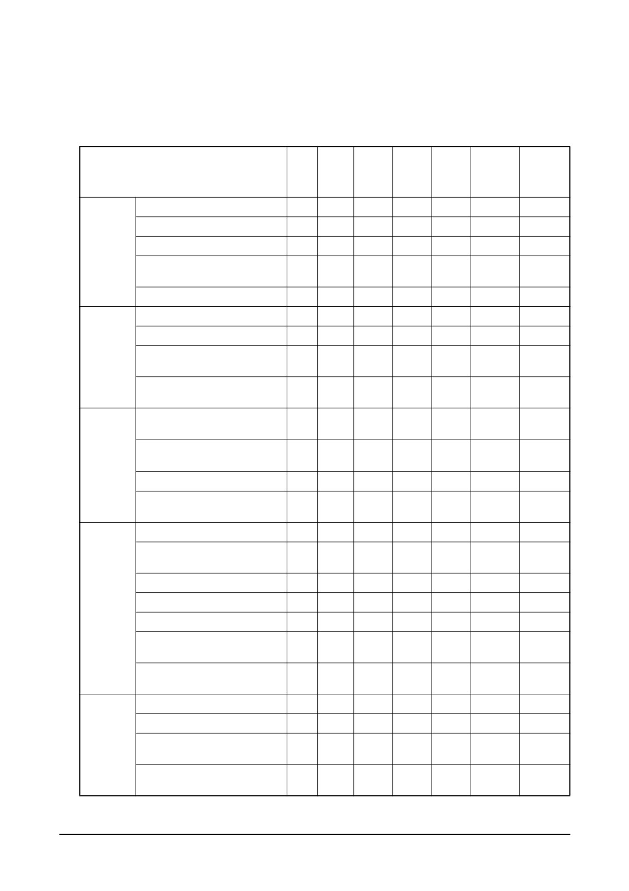
7. Operation Tip
7.1. Periodic Inspection Cycle
{
: Check & adjust z
: Replace
Every
Every
Every
Every
Every
Inspection
Daily
Remark
50hrs
200hrs
400hrs
800hrs
1,200hrs
Check for leakage (hoses, clamp)
{
Check the water level
{
Cooling
Change the coolant water
z
System
Every
Adjust the V-belt tension
{
2,000hrs
Clean the radiator
{
Check for leakage
{
Check the oil level gauge
{
Lubrication
z
Change the lubricating oil
z
System
1st
z
Replace the oil filter cartridge
z
1st
Check the leakage for
{
intercooler (hoses, clamp)
Intake &
Clean and change
{
z
Exhaust
the air cleaner element
clean
System
Clean the inter-cooler air fins
{
Every
Clean the turbo-charger
2,000hrs
Check the leakage fuel line
{
Clean the fuel strainer
{
of fuel feed pump
Remove sediment from fuel tank
{
Fuel
Drain the water in separator
{
System
Drain the water in separator
z
When
Check fuel Injection timing
{
necessary
When
Check the injection nozzles
{
necessary
Check the state of exhaust gas
{
Check the battery charging
{
When
Engine
Check the compression pressure
{
necessary
Adjust
Adjust Intake/Exhaust valve
{
When
clearance
1st
necessary
- 48 -
Operation Tip
7.2. Trouble Shooting
7.2.1. Engine starting impossible
1. Engine Starting Impossible
Starting motor operation poor
Starting motor revolution
Inspection of battery electorlytic
Engine
Fuel
Ilquid amount & gravity
Inspect air cleaner
Inspect amount of fuel
Normal
Too low
Ajustment¡⁄
Normal
Polluted
Normal
None
Recharging
Replace or
Replenish
Inspection of loose electric
clean element
Inspect fuel
wring & short
injection
No injection
Check compression
pressure
Retigten¡⁄
Normal
Normal
Replace
Too low
Continuous
Normal
operation after
Repair¡⁄
Inspection of starting switch
air removal
Replace
Inspect
Repair¡⁄
Inspect of
Normal
injection
Replace
other parts
timing
Check valve
Adjust
Inspection of starting relay
Normal
clearance
Normal
Replace
Inspect injection
Normal
Adjust
nozzle (injection
Inspection of magentic switch
pressure injection
Check cylinder
Replace
state etc.)
Repair
head gasket
Normal
Replace
Repair¡⁄
Normal
Normal
Replace
Starting motor
Engine disassembly
Injection pump
disassembly
(valve assembly piston
disassembly
cylinder liner etc.)
Inspect supply pump operation
Normal
Inspect supply pump valve strainer
Air mixture in fuel
Injection pump
Retighten connection
Clean¡⁄
Normal
dasassembly
parts. Replace gasket
replace
Inspect fuel filter
Air removal
Element polluted
Continuous air mixing
Overflow valve poor
Supply pump
Replace
disassembly
Operation Tip
- 49 -
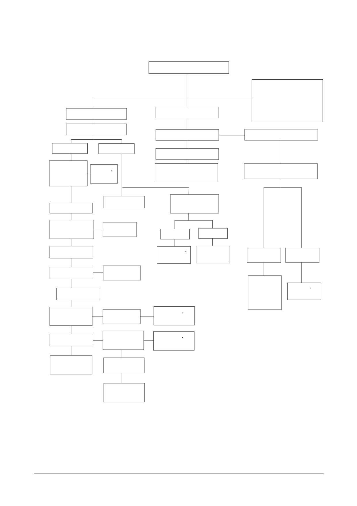
7.2.2. Engine overheated
2. Engine Overheated
Operating state
1. Overload
2. Radiator core clogged
Cooling unit
Fuel unit
3. Continuous over-run
Check coolant
Inspect fuel quality
Fuel excessive supply
Normal
Too low
Poor
Check fan belt
Repair
Clean and replace
Check injection nozzle
tension wear
Replace
with specilied fuel
or damage etc.
Inspect cooling
Replenish
Normal
water leakage
Check fresh
Replace
water tank cap
Exteranl
Internal
Normal
Retighten
Engine
Normal
Abnormal
Replace
disassembly
Check thermostat
Replace
Adjust
repair
Repair
Normal
Replace
injection
pump
Inspect heat
Repair
Damage
exchanger
Replace
Check cooling
Repair
Normal
water pump
Replace
Clean cooling
Normal
water passage
Engine
disassembly
- 50 -
Operation Tip
7.2.3. Output insufficient
3. Output Insufficient
Engine
Installation improper
Check for coupling
Fuel unit
Others
alignemnt
Check for air mixing
Inspect air cleaner
Adjust or replace
in fuel
coupling
Normal
Clean Relpace
Inspect fuel supply pump
Inspect air leakage
Inspect engine control
Normal
Clean Replace
of air piping line
rod, link, cable, etc.
Inspect fuel filter over folw valve
Retighten
Normal
Adjust
Normal
Replace
Normal
Replace
Check valve clearance
Inspect air leakage
Inspect injection pipe
of Intercooler
Normal
Adjust
Normal
Repair Replace
Inspect cylinder head
gasket for damage
Inspect injection nozzle
injection pressure
atomizing state
Normal
Replace
Normal
Adjust Replace
Engine disassembly
(valve assembly)
Check injection timing
Normal
Adjustment
Disassemble engine or
Check Turbocharger
injection pump
Normal
Repair
Replace
Disassemble injection
pump or engine
Operation Tip
- 51 -
7.2.4. Oil pressure lowered
4. Oil pressure lowered
Check if oil pressure
gauge indicates wrongly
Check oil amount
Too low
Normal
Use recommended oil
Check cooling
(replenish)
temperature
Too high
Normal
Refer to engine overhea
Inspect oil quality
Normal
Check oil relief
Water & fuel mixed
Improper
valve
in oil
Replace with
Retighten
Disassemble engine
Normal
recommended oil
Replace
or injection pump
Disassemble
engine
- 52 -
Operation Tip
7.2.5. Fuel consumption
5. Fuel Consumption Excessive
Causes according to Use Conditions
1. Overload
2. Govemor's Arbitrary Adjustment
3. Full Speed Operation for Long time
4. Sudden Speed Change from Low to
Inspect fuel leakage
High Speed
Normal
Oil leakage
Inspect injection nozzle
(injection pressure
Adjust Replace
atomizing state etc.)
Retighten Replace
Normal
Check injection timing
Adjust
Normal
Repair Replace
Inspect compressed
Check valve
Cylinder liner
pressure
clearance
Piston ring Piston
Normal
Disassemble
Adjust
injection pump
Normal
Inspect head gasket
Replace
Normal
Disassemble engine
(valve assembly piston
cylinder liner etc.)
Operation Tip
- 53 -
7.2.6. Oil consumption excessive
6. Oil Consumption Excessive
Cause according to use conditions
1. Excessive oil infusing
2. Continuous operation in low or
extremely cold state
Inspect oil leakage
Inspect air cleaner
Clean Replace
Normal
Oil leakage
External
Internal
Check oil quality
Retighten
Check compressed
Replace with
Replace
pressure
specified oil
Engine disassembly
Normal
(piston cylinder liner)
Disassemble
cylinderhead
(valve stem seal)
7.2.7. Engine knocking
7. Engine Knocking
Inspect combustion of fuel & oil
(carbon residue exhaust gas)
Unconfirmed
Confirm
Inspect compressed
Disassemble
pressure
engine
Too low
Normal
Check valve clearance and
Inspect injection
cylinderhead gasket for damage
pump
Normal
Adjust
Replace
Normal
Adjust
Check fuel quality
Disassemble
engine
Use specified fuel
- 54 -
Operation Tip
7.2.8. Battery discharge
8. Battery Discharge
Generator
Battery
Wiring Switch
Inspect cut wire
Check fan belt
Check electrolytic
shorts and loose
tension & damage
liquid amount
connections
Repair Replace
Normal
Battery self
Battery over
Electrolytic
Battery room
discharge
charging
liquid's
damage
standard
Inspect generator
Replace
Charging
Voltage regulator
Replenish
Abnormal
Normal
Adjust
Check charged stated
Replace
Discharging
Disassemble
generator Voltage
regulator
Operation Tip
- 55 -
7.3. Causes and Remedies
Condition
Causes
Remedies
1) Starting difficult
● Valveís poor shut, stem distortion
Repair or replace
(1) Compression pressure
● Valve spring damage
Replace valve spring
● Cylinder head gasket’s leak
Replace gasket
● Wear of piston, piston ring or liner
Adjust
2) Idle operation abnormal
● Injection timing incorrect
Adjust
● Air mixing at injection pump
Remove air
Adjust
3) Engine output insufficient
● Valve clearance incorrect
Repair
(1) Continuous output insuffi-
● Valve tightness poor
Replace gasket
cient
● Cylinder head gasket’s leak
Replace piston ring
● Wear, stick, damage of piston ring
Adjust
● Injection timing incorrect
Adjust injection pump
● Fuel injection amount insufficient
Adjust or replace
● Nozzle injection pressure improper or stuck
Repair or replace
● Supply pump’s function lowered
Repair
● Fuel pipe system clogged
Clean or replace air
● Air suction amount insufficient
cleaner
● Supercharger poor
Repair or replace
(2) Output insufficient when in
● Compression pressure insufficient
Disassemble engine
acceleration
● Injection timing incorrect
Adjust
● Fuel injection amount insufficient
Adjust injection pump
● Injection pump timer’s function insufficient
Repair or replace
● Nozzle infection pressure, infection angle
Repair, replace
improper
● Supply pump’s function lowered
Repair or replace
● Air intake amount insufficient cleaner
Clean or replace air
4) Overheating
● Engine oil insufficient or poor
Replenish or replace
● Cooking water insufficient
Replenish or replace
● Fan belt loosened, worn, damaged
Adjust or replace
● Cooling water pump’s function lowered
Repair or replace
● Water temp. regulator’s operation poor
Replace
● Valve clearance incorrect
Adjust
● Exhaust system’s resistance increased
Clean or replace
5) Engine noisy
For noises arise compositely such asrota ting
parts, lapping parts etc., there is nec essity to
search the cause of noises accurately.
(1) Crankshaft
● As the wear of bearing or crankshaft
Replace bearing & grind
progress, the oil clearances increase.
crankshaft
● Lopsided wear of crankshaft
Grind or replace
● Oil supply insufficient due to oil passage
Clean oil passage
clogging
● Stuck bearing
Replace bearing & Grind
- 56 -
Operation Tip
Condition
Causes
Remedies
(2) Con rod and Con rod
● Lopsided wear of con rod bearing
Replace bearing
bearing
● Lopsided wear of crank pin
Grind crankshaft
● Connecting rod distortion
Repair or replace
● Stuck bearing
Replace & grind crank-
● Oil supply insufficiency as clogging at oil
shaft
passage progresses
Clean oil passage
(3) Piston, piston pin &
● Piston clearance increase as the wear of
Replace piston & piston
piston ring
piston and piston ring progresses
ring
● Wear of piston or piston pin
Replace
● Piston stuck
Replace piston
● Piston insertion poor
Replace piston
● Piston ring damaged
Replace piston
(4) Others
● Wear of crankshaft, thrust bearing bearing
Replace thrust
● Camshaft end play increased
Replace thrust plate
● Idle gear end play increased
Replace thrust washer
● Timing gear backlash excessive
Repair or replace
● Vale clearance excessive
Adjust valve clearance
● Abnormal wear of tappet, cam
Replace tappet, cam
● Supercharger inner part damaged
Repair or replace
● Injection timing incorrect
Adjust
6) Fuel Consumption Exttive
● Fuel injection amount excessive
Adjust injection pump
7) Oil Consumption Excessive
(1) Oil level elevated
● Clearance between cylinder iner & piston
Replace
● Wear of piston ring, ring groove
Replace piston, piston ring
● Piston ring’s damage, stick, wear
Replace piston ring
● Piston ring opening’s disposition improper
Correct position
● Piston skirt part damaged or abnormal wear
Replace piston
● Oil ring’s oil return hole clogged
Replace piston ring
● Oil ring’s contact poor
Replace piston ring
(2) Oil level lowered
● Looseness of valve stem & guide
Replace in set
● Wear of valve stem seal
Replace seal
● Cylinder head gasket’s leak
Replace gasket
(3) Oil leak
● Looseness of connection parts
Replace gasket, repair
● Various part’s packing poor
Replace packing
● Oil seal poor
Replace oil seal
Operation Tip
- 57 -
8. General Information
8.1. General Repair Instructions
1)
Before Performing service operation, disconnect the grounding cable from the battery for reduc-
ing the chance of cable damage and burning due to short-circuiting.
2)
Use covers for preventing the components from damage or pollution.
3)
Engine oil and anti-freeze solution must be handled with reasonable care as they cause paint
damage.
4)
The use of proper tools and special tools where specified is important to efficient and reliable
service operation.
5)
Use genuine DOOSAN parts necessarily.
6)
Used cotter pins, gaskets, O-rings, oil seals, lock washer and self-lock nuts should be dis-
carded and new ones should be prepared for installation as normal function of the parts can
not be maintained if these parts are reused.
7)
To facilitate proper and smooth reassemble operation, keep disassembled parts neatly in
groups. Keeping fixing bolts and nut separate is very important as they vary in hardness design
depending on position of lnstallation.
8)
Clean the parts before inspection or reassembly. Also clean oil ports, etc. using compressed air
to make certain they are free from restrictions.
9)
Lubricate rotating and sliding faces of parts with oil or grease before installation.
10) When necessary, use a sealer on gaskets to prevent leakage.
11) Carefully observe all specifications for bolts and nuts torques.
12) When service operation is completed, make a final check to be sure service has been done
property.
-
58 -
General Information
8.2. Engine Characteristics
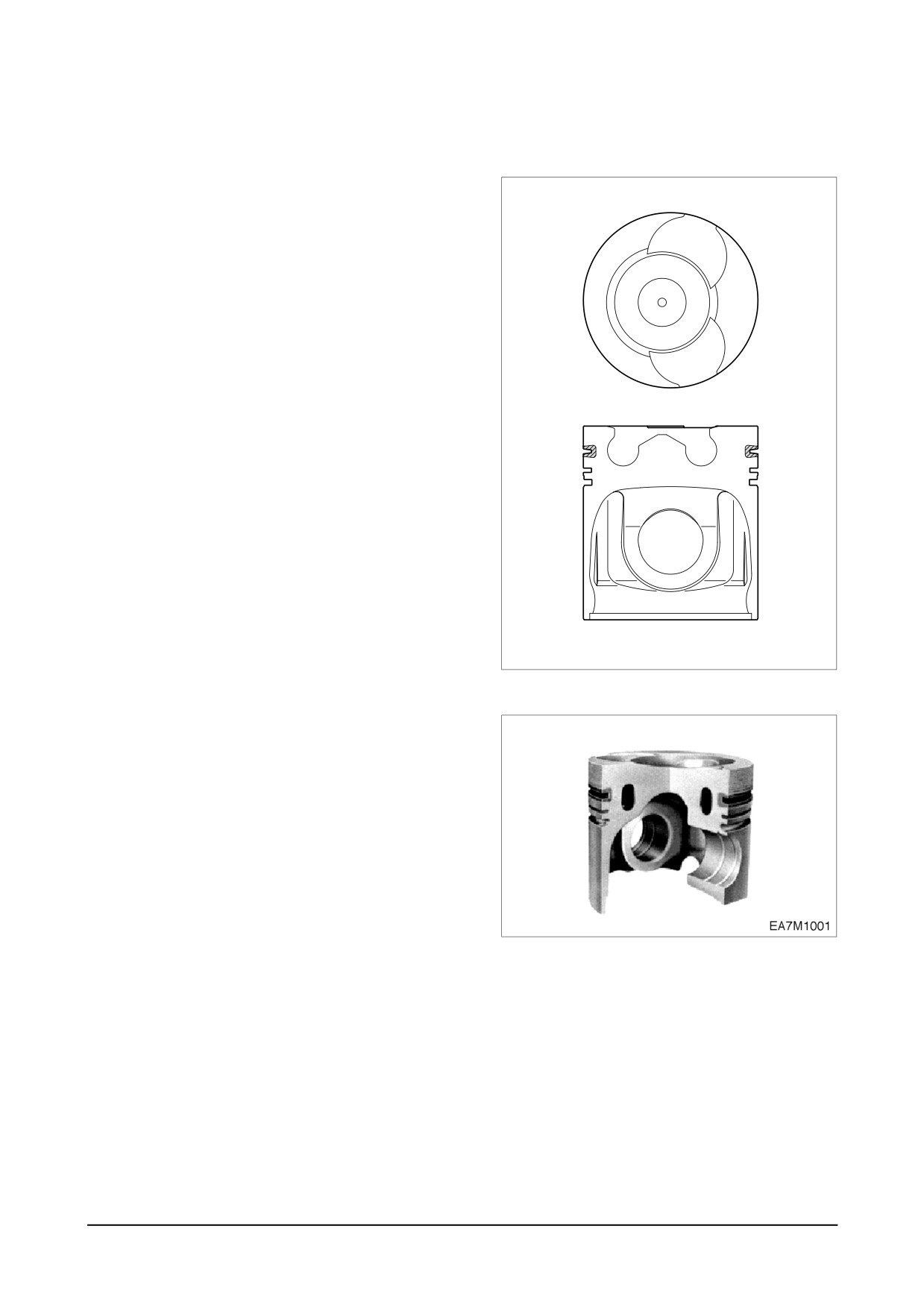
8.2.1. OMEGA combustion bowl
The OMEGA combustion bowl is a unit
designed to perform high efficiency, low
emission combustion. As the rim around
the combustion bowl port of the upper of
the piston has been machined in a
smaller size than the interior of the com-
bustion bowl, strong swirl is produced in
the combustion bowl and strong squish
flow makes the fuel be mixed more suffi-
ciently with air.
Due to the application of OMEGA com-
bustion system and optimal utilization of
intake and exhaust port configuration
within the cylinder head, the P126TI
series, DE12T and PU126TI engines dis-
charge very low level of hazardous
exhaust gases such as smoke, nitrogen
oxide, hydrocarbon, or carbon monoxide
and thus ensure high performance and
low fuel consumption.
EA8M1001
8.2.2. Oil gallery cooling type piston (P126TI / PU126TI)
Oil gallery cooling is used for the piston
of P126TI series and PU126TI engine.
When thermal loading is high, piston cool-
ing by means of an oil gallery in the
crown is normally necessary to prevent
crown cracking and ring sticking. The
design of the gallery, the design and
location of the oil spray nozzle and the
quantity of oil flowing in the gallery are
critical in order to achieve the desired
temperature reduction.
The cross section shape of the gallery
should be designed to achieve sufficient
oil movement to maximize cooling effi-
ciency.
General Information
-
59 -
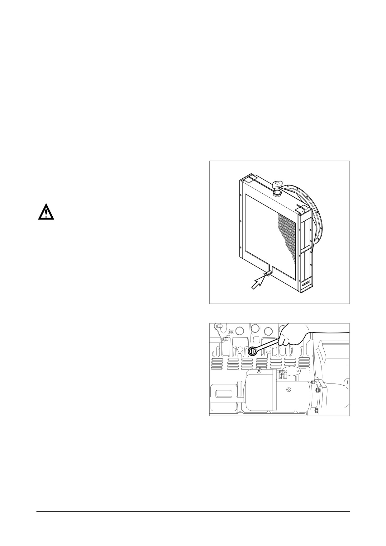
9. Disassembly and Reassembly of Major Components
9.1. Disassembly
9.1.1. General precautions
● Maintenance operation should be carried out in a bright and clean place.
● Before disassembly, provide parts racks for storage of various tools and disassembled parts.
● Arrange the disassembled parts in the disassembly sequence and use care to prevent any
damage to them.
9.1.2. Cooling water
● Remove the radiator cap. Open the
drain plug at the radiator lower part to
drain the coolant as the right figure.
CAUTION :
When removing radiator filler cap
while the engine is still hot, cover
the cap with a rag, then turn it
slowly to release the internal steam
pressure This will prevent a person
from scalding with hot steam
spouted out from the filler port.
Drain Valve
EA5O4002
● Remove the drain plug from the cylin-
der block and drain out the cooling
water into a container.
EI7OM003
D
-
60 -
isassembly and Reassembly of Major Components
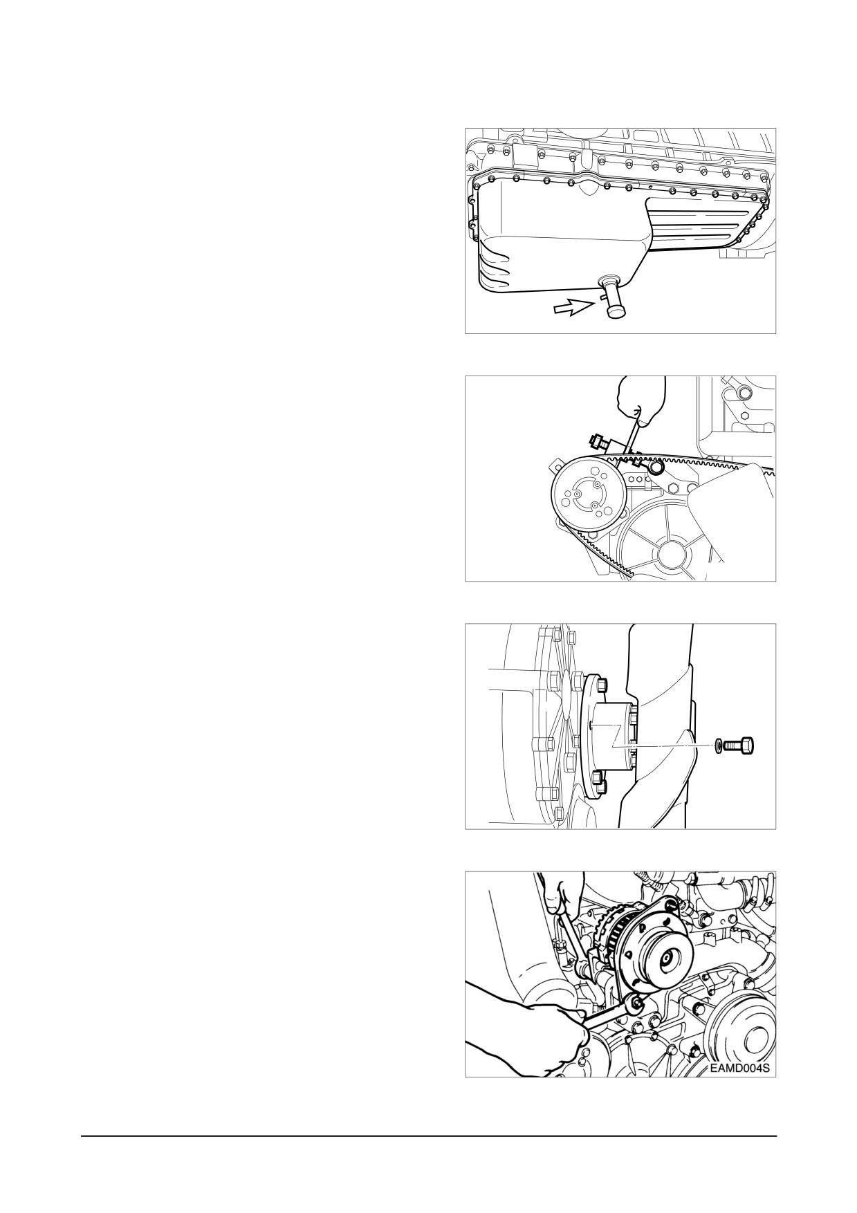
9.1.3. Engine oil
● Take out the oil dipstick.
● Remove the oil drain valve of oil pan
and drain out the engine oil into a pre-
pared container.
Drain valve
EA8O5001
9.1.4. Alternator belt
● Loosen the tension adjusting nut
installed on the alternator bracket, and
take off the alternator belt.
EA8M3001
9.1.5. Cooling fan
● Remove the flange fixing bolts, then
take off the flange and cooling fan.
EQM3004I
9.1.6. Alternator
● Remove the alternator fixing bolt and
disassemble the alternator.
● Remove the tension adjusting bolt and
bracket.
Disassembly and Reassembly of Major Components
-
61 -
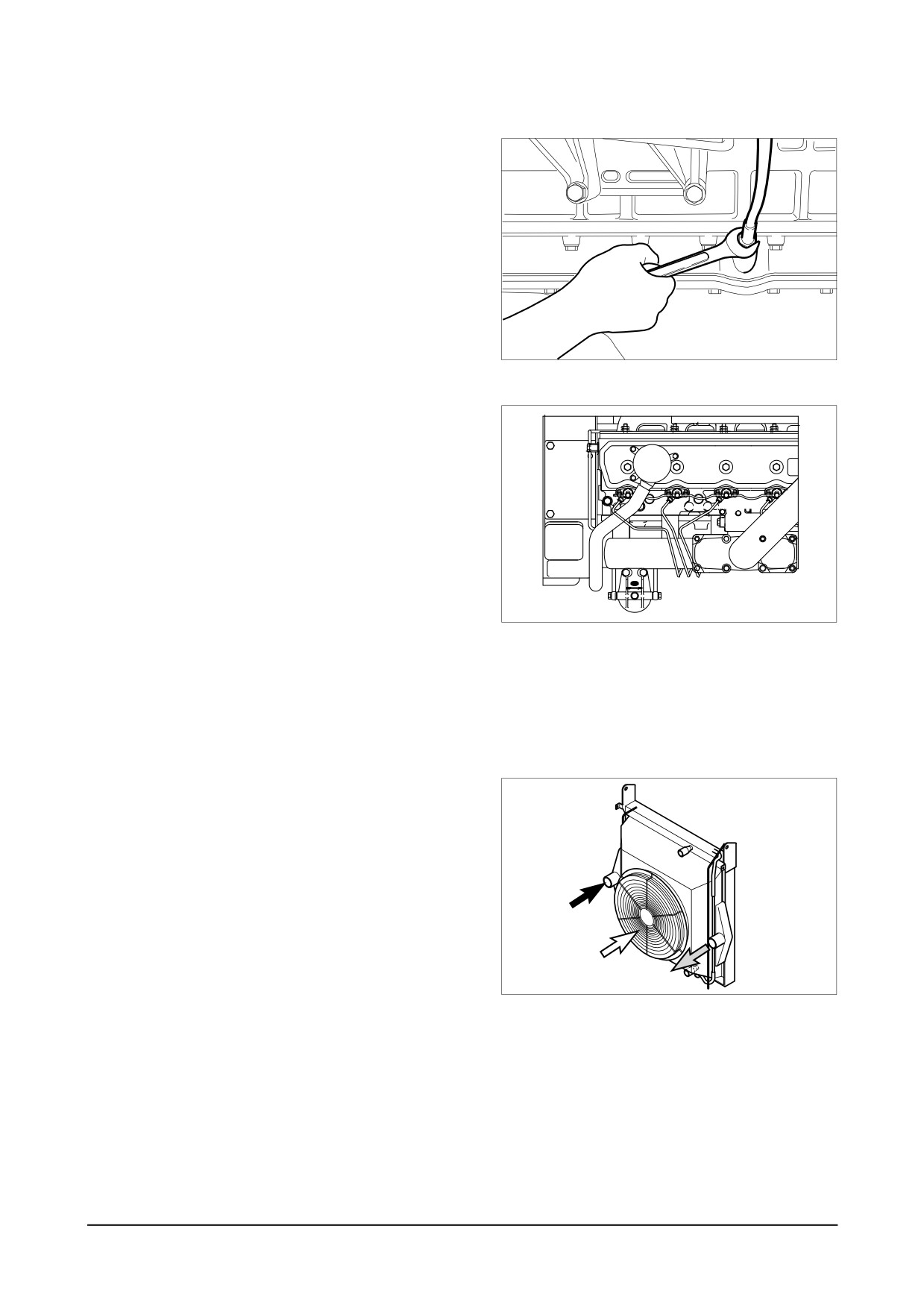
9.1.7. Guide tube of oil level gauge
● Loosen the flange nut installed on the
oil pan to remove the guide tube.
EQM3005I
9.1.8. Fuel filter
● Remove fuel hoses connected to the
fuel injection pump, take off the
bracket fixing bolts, then disassemble
the fuel filter.
EI6OM016
9.1.9. Breather
● Loosen the clamp screw to remove the
rubber hose.
9.1.10. Intercooler
● Tear down the various hoses and air
pipes from the inter cooler.
● Remove the intercooler fixing bolts
and tear it down.
EA6M2001
D
-
62 -
isassembly and Reassembly of Major Components
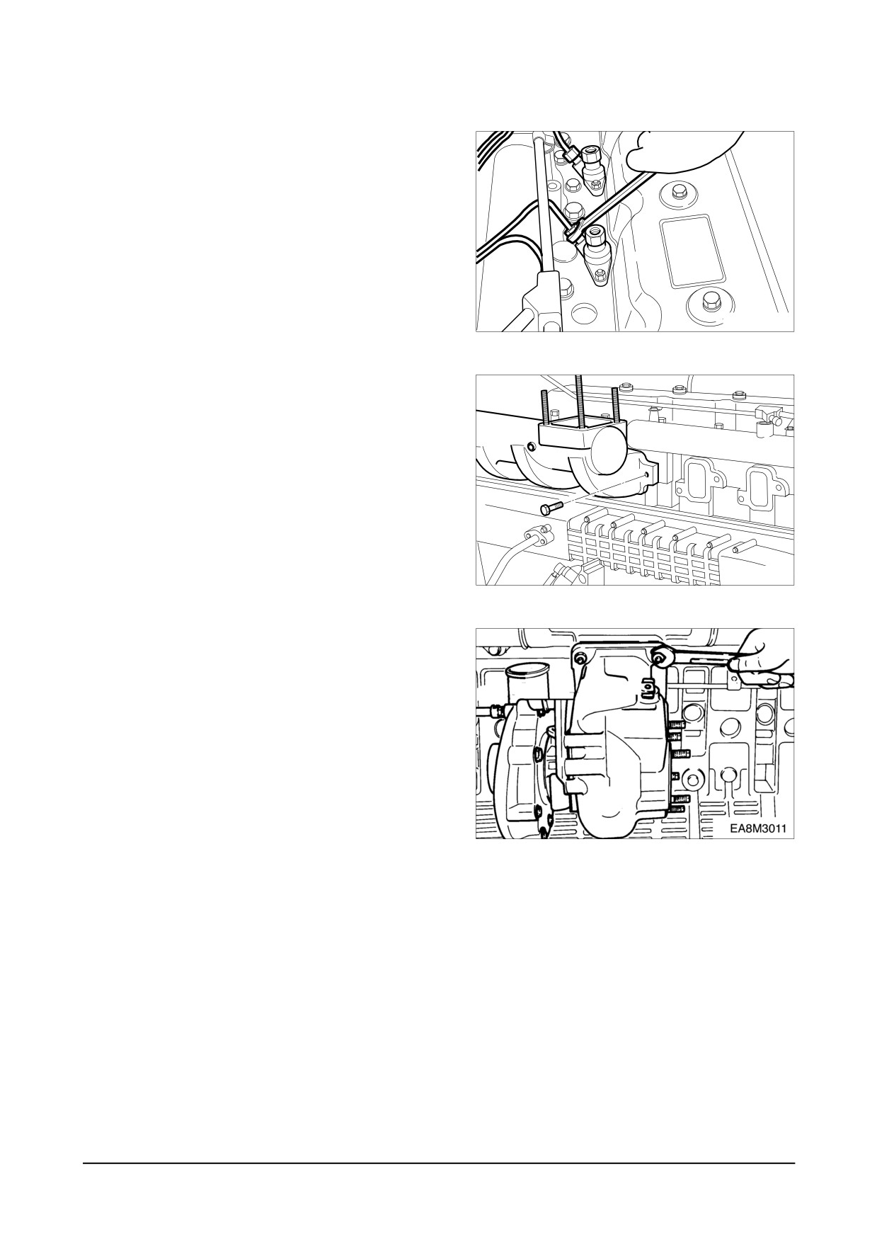
9.1.11. Injection pipe
● Unscrew the hollow screws to disas-
semble the fuel return pipe.
● Remove the nuts installed on the fuel
injection pump and nozzles, then dis-
assemble the injection pipe.
EQM3009I
9.1.12. Intake manifold
● Remove the air hose connected to
the fuel injection pump.
● Loosen the intake manifold fixing
bolts, then disassemble the intake
manifold.
EQM3011I
9.1.13. Turbo charger
● Release the clamp screw of the rub-
ber hose connected to the intake
manifold, and take off the intake
pipes both simultaneously.
● Unscrew the exhaust pip5e bracket
fixing bolts, release the nuts installed
on the turbocharger, then disassem-
ble the exhaust pipe.
● Remove the turbocharger after remov-
ing the oil supply pipe and return
pipe and releasing the fixing nuts.
Disassembly and Reassembly of Major Components
-
63 -
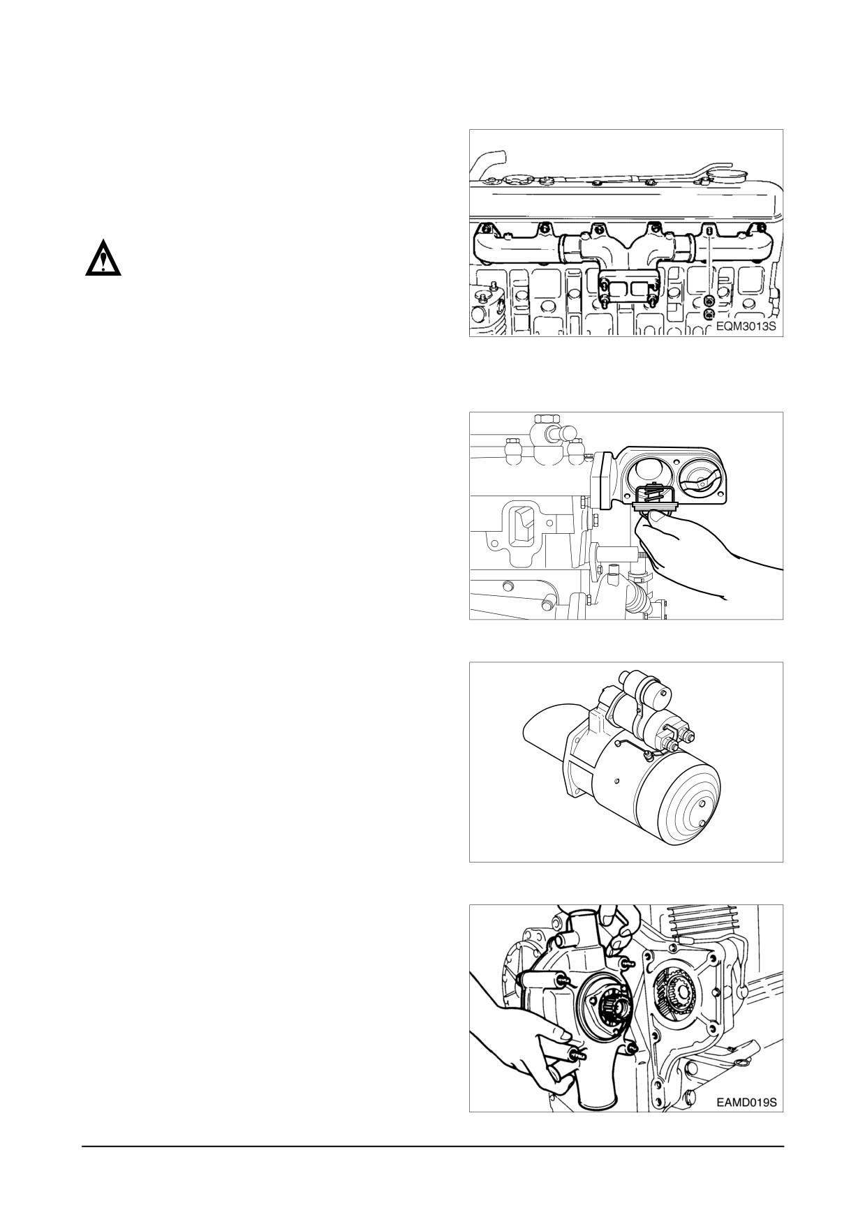
9.1.14. Exhaust manifold
● Release the exhaust manifold fixing
bolts, disassemble the exhaust mani-
fold, then remove the heat shield and
gasket.
NOTE :
Make sure to release the nuts one
after another because the exhaust
manifold will be removed if you
unscrew two nuts simultaneously.
9.1.15. Thermostat
● Remove the by-pass pipe connected to
the water pump, unscrew the thermostat
fixing bolts, then disassemble the ther-
mostat housing.
● Disassemble the thermostat housing
and remove the thermostat.
● Disassemble the water pipe by
unscrewing the bolts and nuts
installed on the cylinder head.
EAMD014I
9.1.16. Starter
● Unscrew the starter fixing bolts, then
disassemble the starter.
ED5OM009
9.1.17. Water pump
● Remove the water pipe connected to
the expansion tank.
● Remove the water pipe and hoses
connected to the water pump.
● Unscrew the water pump fixing bolts
and remove the water pump.
-
D
64 -
isassembly and Reassembly of Major Components
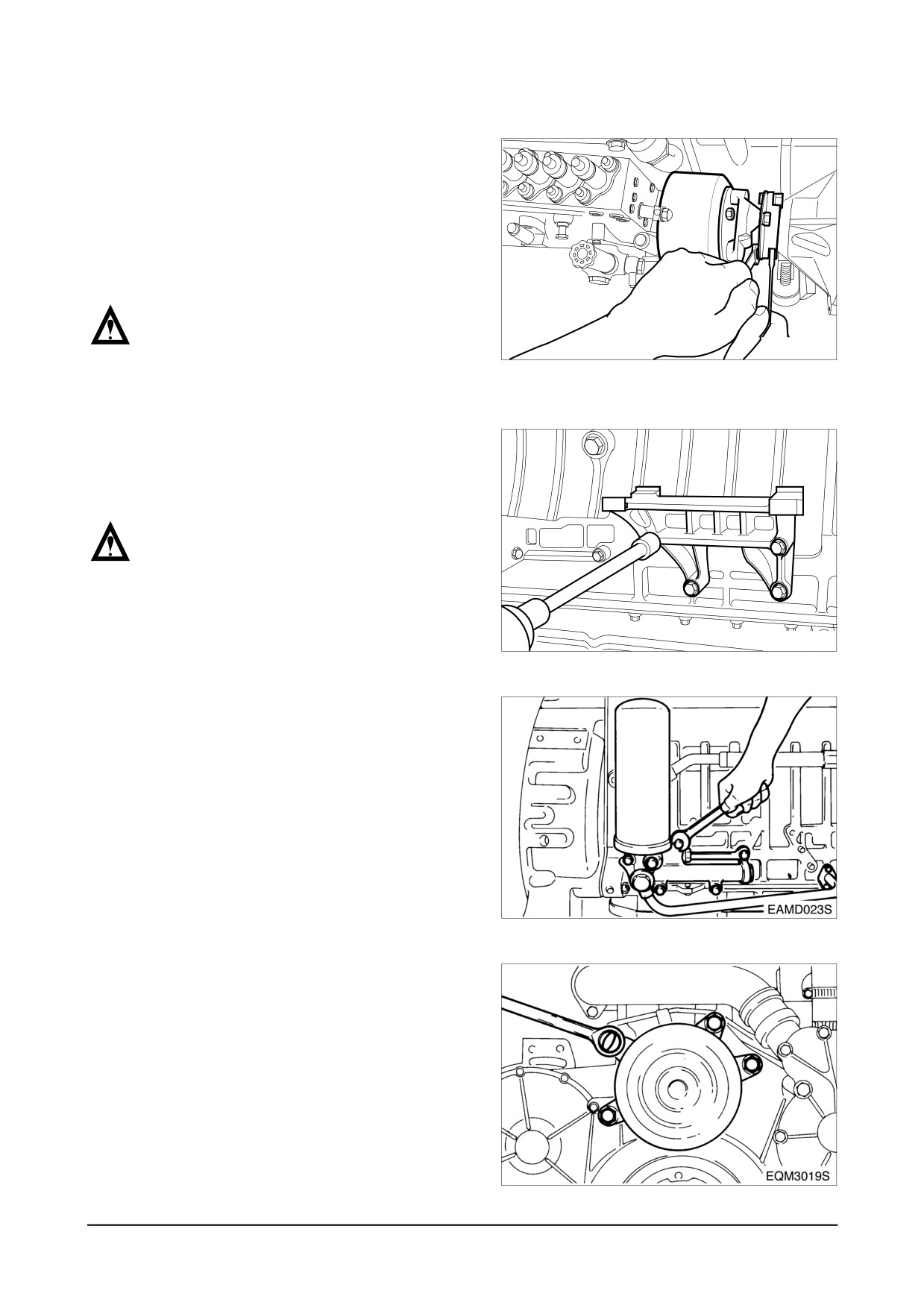
9.1.18. Injection pump
● Remove the oil supply pipe and return
pipe connected to the fuel injection pump.
● Unscrew the bolts connecting the
coupling and drive shaft, disassemble
the injection pump mounting bolts,
then detach theinjection pump.
NOTE :
After letting No.1 cylinder to the 'OT'
EAMD021I
position by turning the crankshaft,
disassemble the injection pump.
● Release the pump fixing bracket bolts
to disassemble the bracket from the
cylinder block.
NOTE :
Do not mix the disassembled shims.
These should be reassembled to the
original position.
EAMD022I
9.1.19. Oil filter
● Using a filter remover wrench, remove
the oil filter cartridge.
● Remove the pipe connected to the oil
cooler.
● Loosen the oil filter fixing bolts and dis-
assemble the oil filter head from the
cylinder block.
9.1.20. Fan drive pulley
● Remove the bolts and disassemble
the fan drive pulley.
Disassembly and Reassembly of Major Components
-
65 -
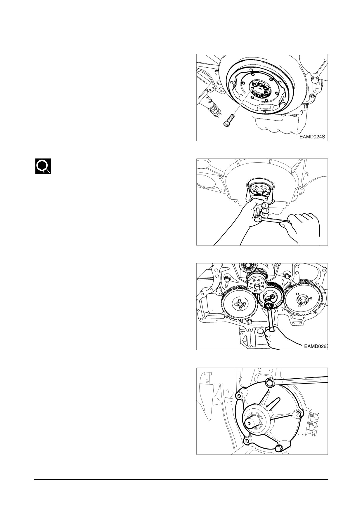
9.1.21. Vibration damper
● Unscrew the pulley fixing bolts and
disassemble
the
pulley-vibration
damper assembly.
● Unscrew the vibration damper fixing
bolts and disassemble the damper
from the pulley.
9.1.22. Timing gear case cover
● Disassemble the oil seal using an oil
seal removing jig.
● Remove the cover fixing bolts and
disassemble the cover from the timing
gear case.
EAMD025I
9.1.23. Idle gear
● Unscrew the idle gear fixing bolts and
disassemble the thrust washer and
idle gear.
● Disassemble the idle gear pin using a
rubber hammer to prevent damage to
them.
9.1.24. Fuel injection pump drive assembly
● Unscrew the injection pump drive
shaft bearing housing fixing bolts and
remove the injection pump drive
assembly which the shaft, gear, bear-
ings, and housing are put together.
EAMD027I
-
D
66 -
isassembly and Reassembly of Major Components
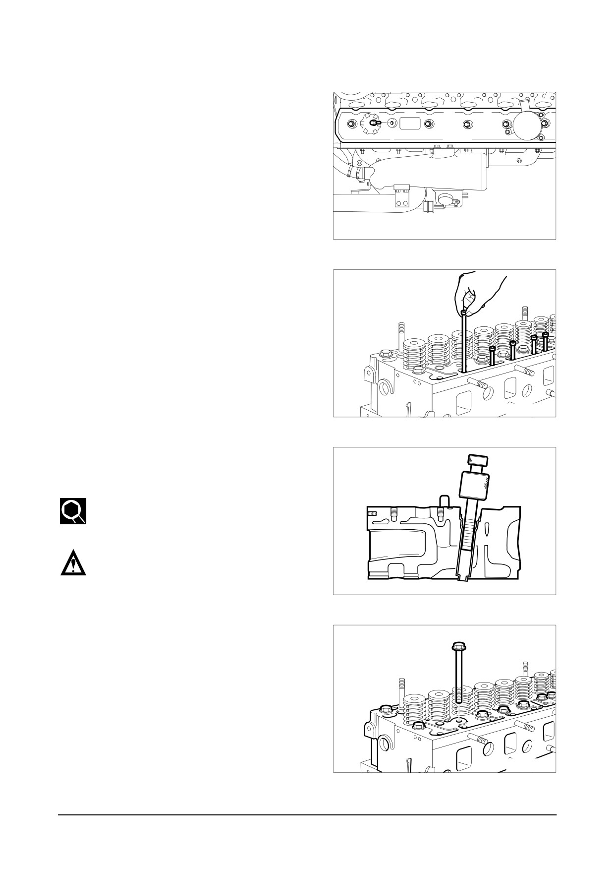
9.1.25. Cylinder head cover
● Unscrew the cover fixing bolts and
disassemble the cover.
● Keep the bolts in an assembly state
so that the packings and washers
may not be lost, and keep the cover
packing as assembled with the cover.
EI7OM005
9.1.26. Rocker arm assembly
● Unscrew the rocker arm bracket bolts
and remove the rocker arm assembly.
● Take off the snap rings to remove
the washers and rocker arm, then
unscrew the bracket fixing bolts to
take off the bracket and springs.
● Take out the push rods.
EAMD029I
9.1.27. Injection nozzle
● Take off the injection pipes between
the injection pump and injection noz-
zles.
● Remove the nozzle tube using nozzle
tube removing jig.
Do not disassemble injection nozzle
unless coolant or gas come out.
EAMD030I
9.1.28. Cylinder head
● Unscrew the cylinder head fixing bolts
and take off the cylinder head.
● Remove the cylinder head gasket.
EAMD031I
Disassembly and Reassembly of Major Components
-
67 -
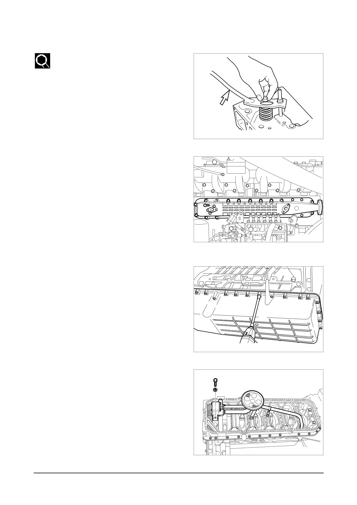
9.1.29. Valve & valve stem seal
● Compress the valve spring retainer
using a jig and take off the valve cot-
ter pins.
● Disassemble the valve springs and
retainers.
● Take off the valves.
Valve spring
● Remove using a general tool and dis-
compressor
card the valve stem seals in order
not to be re-used.
EA0M4007
9.1.30. Oil cooler
● Remove the water pipe connected to
the water pump.
● Remove the oil pipe connected to the
cylinder block.
● Unscrew the oil cooler cover fixing
bolts and disassemble the oil cooler
assembly from the cylinder block.
● Unscrew the oil cooler fixing bolts
and remove the oil cooler from the oil
EAMD033I
cooler cover.
9.1.31. Oil pan
● Stand the engine with the flywheel
housing facing the bottom.
● Release the oil pan fixing bolts,
remove the stiffeners then disassem-
ble the oil pan.
EAMD034I
9.1.32. Oil pump & oil pipe
● Unscrew the oil suction pipe bracket
bolts, releasing the pipe fixing bolts,
then disassemble the oil suction pipe
assembly.
● Disassemble the oil pipe feeding oil
from the oil pump to the cylinder
block.
● Unscrew the oil pump fixing bolts and
disassemble the oil pump.
EAMD035I
D
-
68 -
isassembly and Reassembly of Major Components
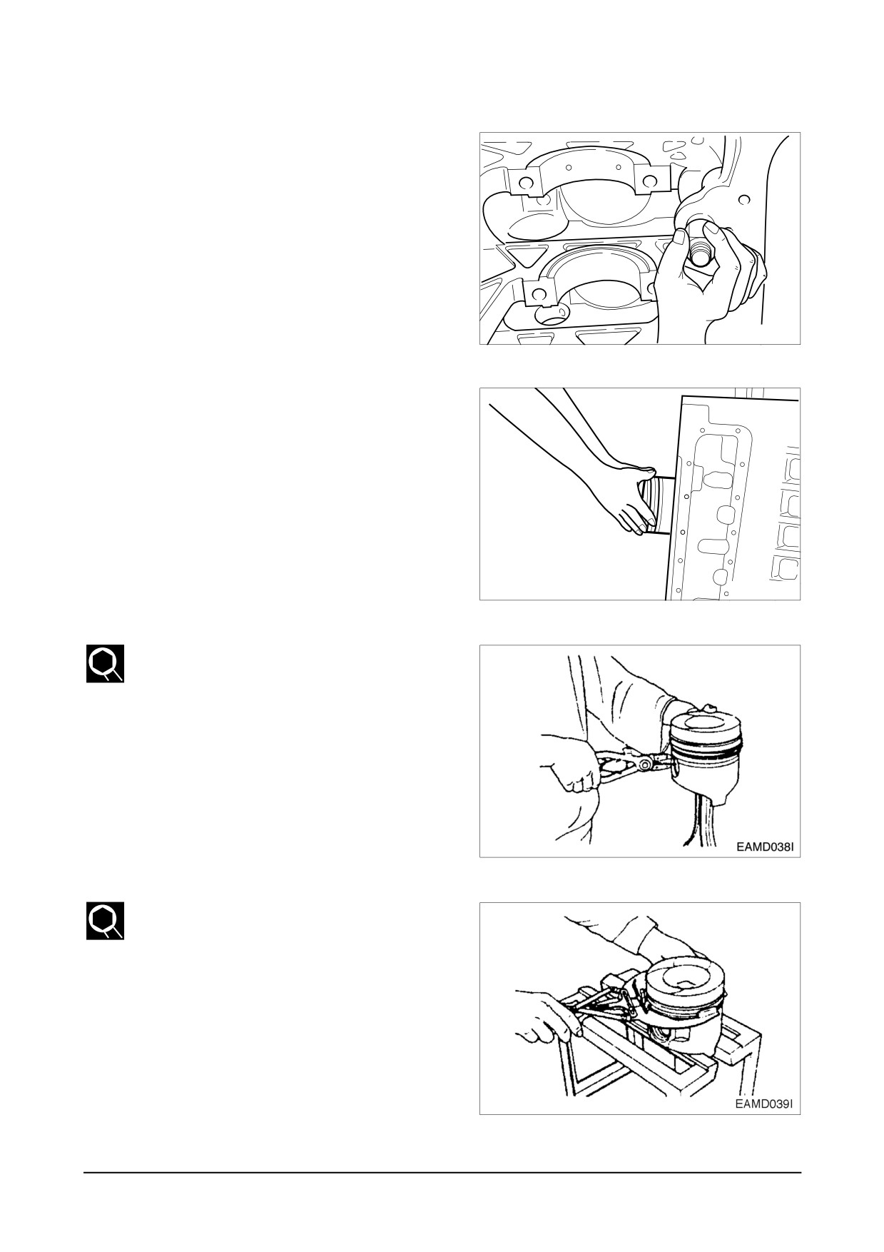
9.1.33. Relief valve
● Disassemble the relief valve.
EAMD036I
9.1.34. Piston & connection rod
● Disassemble the pistons by two cylin-
ders while turning the crankshaft.
● Unscrew the connecting rod fixing
bolts and take off the pistons and
connecting rods in the direction of
piston.
EAMD037I
● Remove the piston pin snap rings,
take off the piston pin, then discon-
nect the connecting rod from the pis-
ton.
● Disassemble the piston rings using
ring pliers.
● Use care not to interchange the dis-
assembled parts and keep them in
the sequence of cylinder No.
Disassembly and Reassembly of Major Components
-
69 -
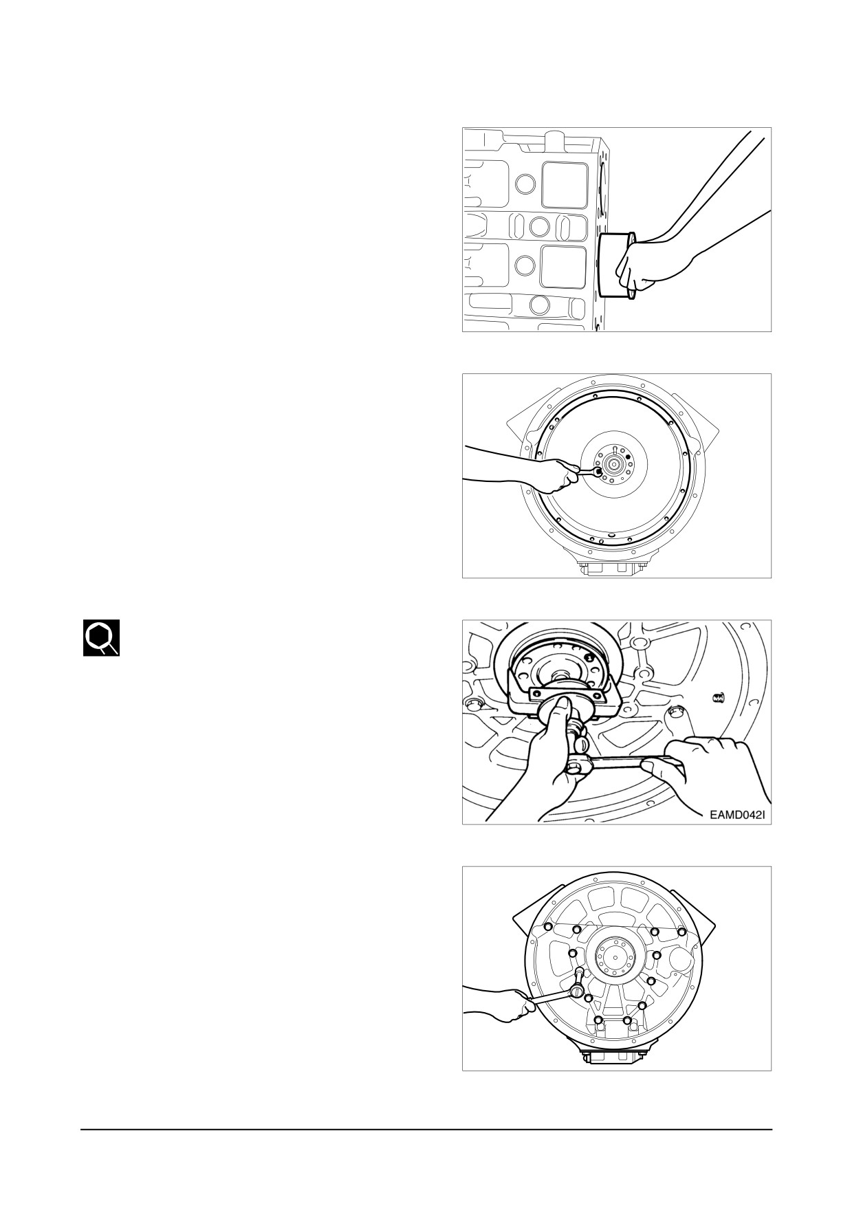
9.1.35. Cylinder liner
● Disassemble the cylinder liner using a
liner puller.
EAMD040I
9.1.36. Flywheel
● Position the engine so that the head
installing surface of the cylinder block
faces down.
● Unscrew the flywheel fixing bolts and
fit a dowel pin.
● Install flywheel disassembling bolts in
the bolt holes machined on the fly-
wheel, and disassemble the flywheel.
EAMD041I
9.1.37. Oil seal
● Take off the rear oil seal using an oil
seal disassembling jig.
● If only the inside guide ring is
removed, use a special tool to take
off the outside seal.
9.1.38. Flywheel housing
● Loosen the housing fixing bolts disas-
semble the flywheel housing.
EAMD043I
-
D
70 -
isassembly and Reassembly of Major Components
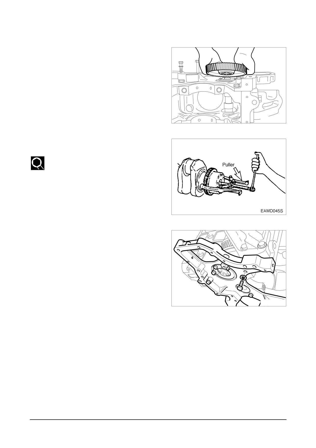
9.1.39. Cam shaft & tappet
● Remove the cam shaft gear.
● Take off the cam shaft gear thrust
washer.
● Take out the cam shaft using care
not to damage the cam shaft.
● Slide out the tappets by hand.
EAMD044I
9.1.40. Crankshaft gear & oil pump idle gear
● Loosen the socket head bolts and
take out the oil pump idle gear.
● Use a puller to remove the crankshaft
gear.
9.1.41. Timing gear case
● Unscrew the case fixing bolts and
disassemble the timing gear case.
EAMD046I
Disassembly and Reassembly of Major Components
-
71 -
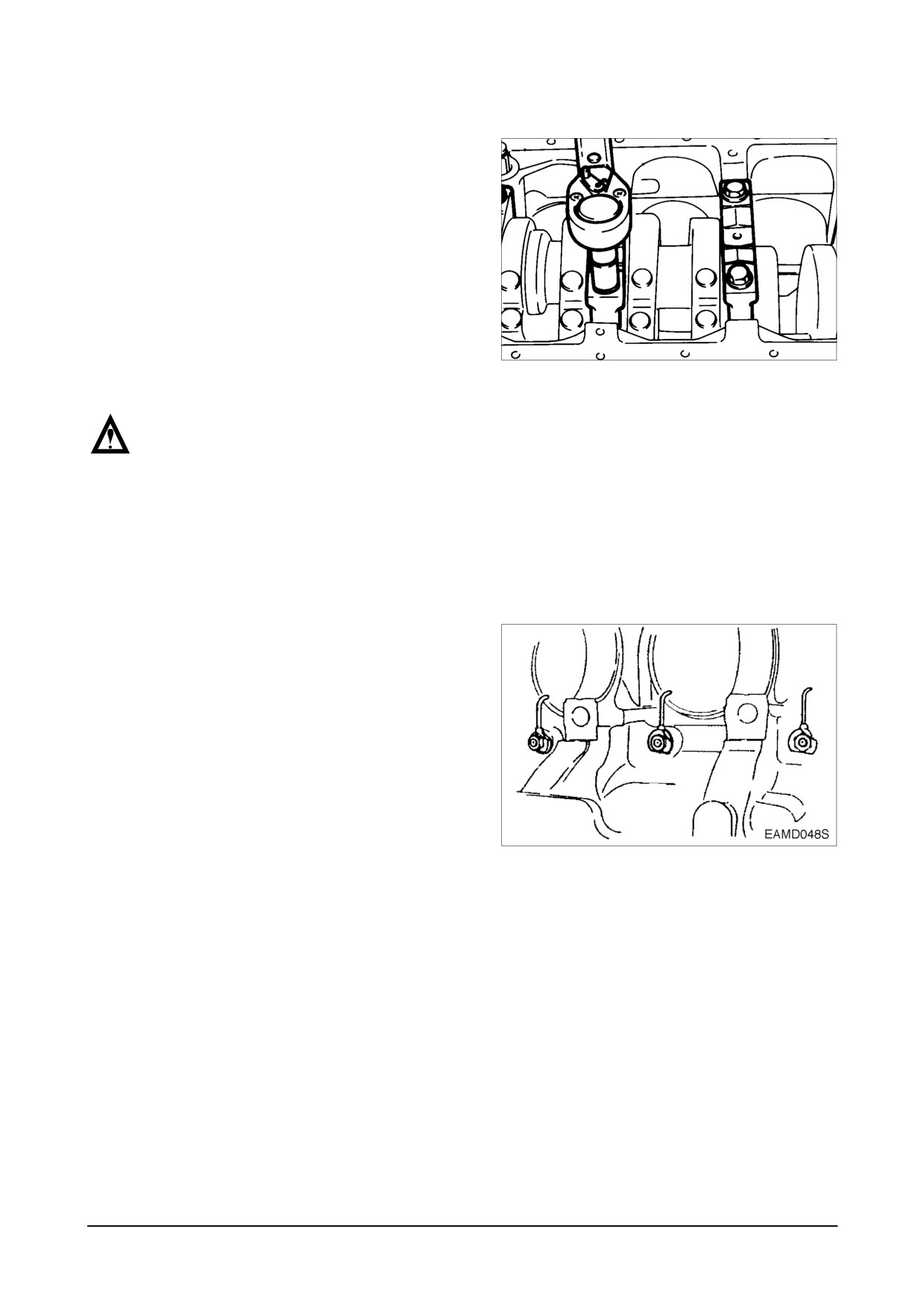
9.1.42. Crankshaft
● Remove the bolts from bearing caps.
● Remove the main bearing cap fixing
bolts in the order of assembling.
● (Remove them in the same way of
the cylinder head bolts.)
● Maintain the removed bearing caps in
the order of cylinders.
● Temporarily install the bolts at the
both side of crankshaft, and lift the
shaft with a rope.
NOTE :
Do not mingle with the metal
bearings and bearing caps randomly.
To prevent mixing, temporarily
assemble the metal bearings to the
corresponding bearing caps in turn.
9.1.43. Oil spray nozzle
● Unscrew the fixing bolt and remove
the oil spray nozzles.
-
D
72 -
isassembly and Reassembly of Major Components
9.2. Inspection
9.2.1. Cylinder block
1) Clean the cylinder block thoroughly and make a visual inspection for cracks or damage.
2) Replace if cracked or severely damaged, and correct if slightly damaged.
3) Check oil and water flow lines for restriction or corrosion.
4) Make a hydraulic test to check for any cracks or air leaks. (Hydraulic test) :
5) Stop up each outlet port of water/oil passages in the cylinder block, apply air pressure of
about 4 kg/cm2 against the inlet ports, then immerse the cylinder block in water for about 1
minute to check any leaks. (Water temperature: 70C)
9.2.2. Cylinder head
1)
Inspection
● Carefully remove carbon from the lower face of the cylinder head using nonmetallic mate-
rial to
prevent scratching of the valve seat faces.
● Check the entire cylinder head for very fine cracks or damage invisible to ordinary sight
using a hydraulic tester or a magnetic flaw detector.
2)
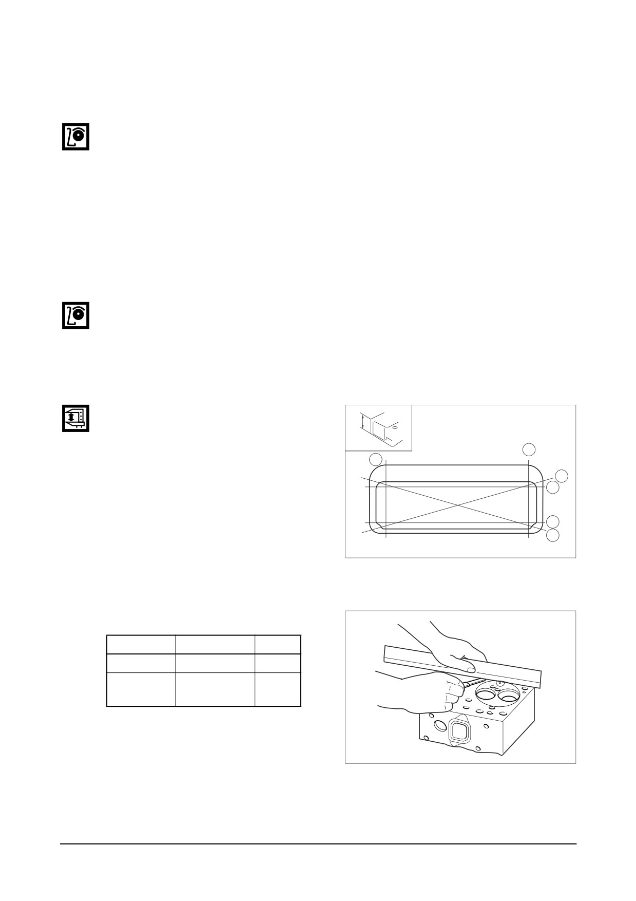
Distortion at the lower face
● Measure the amount of distortion
(t)
using a straight edge and a feeler
gauge at six positions
(A
~ F) as
B
shown in the right figure.
A
● If the measured value exceeds the
C
D
standard value, retrace the head
with grinding paper of fine grain
E
size to correct such defect.
F
● If the measured value exceeds the
EA3M2031
maximum allowable limit, replace
the cylinder head.
<Lower face warpage and height>
(mm)
Standard
Limit
Warpage
0.2 or less
0.3
Thickness : t
114.95 ~ 115.0
113.9
(reference)
EA6M2002
Disassembly and Reassembly of Major Components
-
73 -
3) flatness
Measure flatness of the intake/
exhaust manifolds fitting surfaces on
the cylinder head using a straight
edge and a feeler gauge.
(mm)
Standard
Limit
0.05
0.2
4) Hydraulic test
Hydraulic test method for the cylinder
head is same as that for cylinder block.
9.2.3. Valve and valve guide
1)
Valve
Clean the valves with clean diesel oil,
then inspect them as follows:
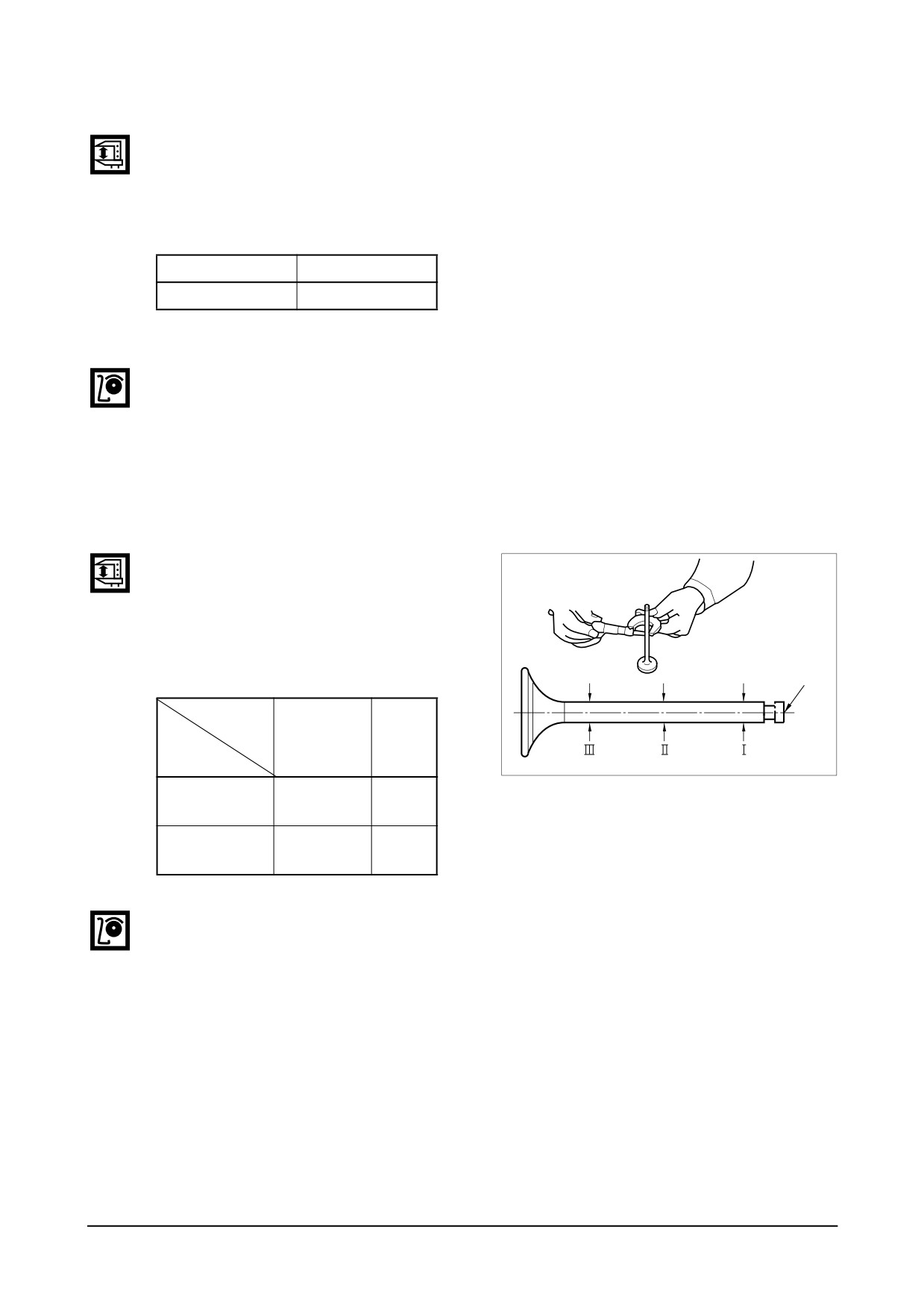
● Valve stem outer diameter
Measure the valve stem outer diam-
eter at 3 positions. (top, middle, and
bottom) If the amount of wear is
beyond the limit, replace the valve.
End of stem
(mm)
Dimension
Standard
Limit
Description
EFM2036I
Intake valve
Ø10.950 ~
Ø10.87
stem
Ø10.970
Exhaust valve
Ø10.935 ~
Ø10.84
stem
Ø10.955
● Valve seat contacting faces
Check the valve seat contacting
faces for scratches or wear, and
correct the faces with grinding paper
as necessary. Replace if severely
damaged.
D
-
74 -
isassembly and Reassembly of Major Components
● Valve head thickness
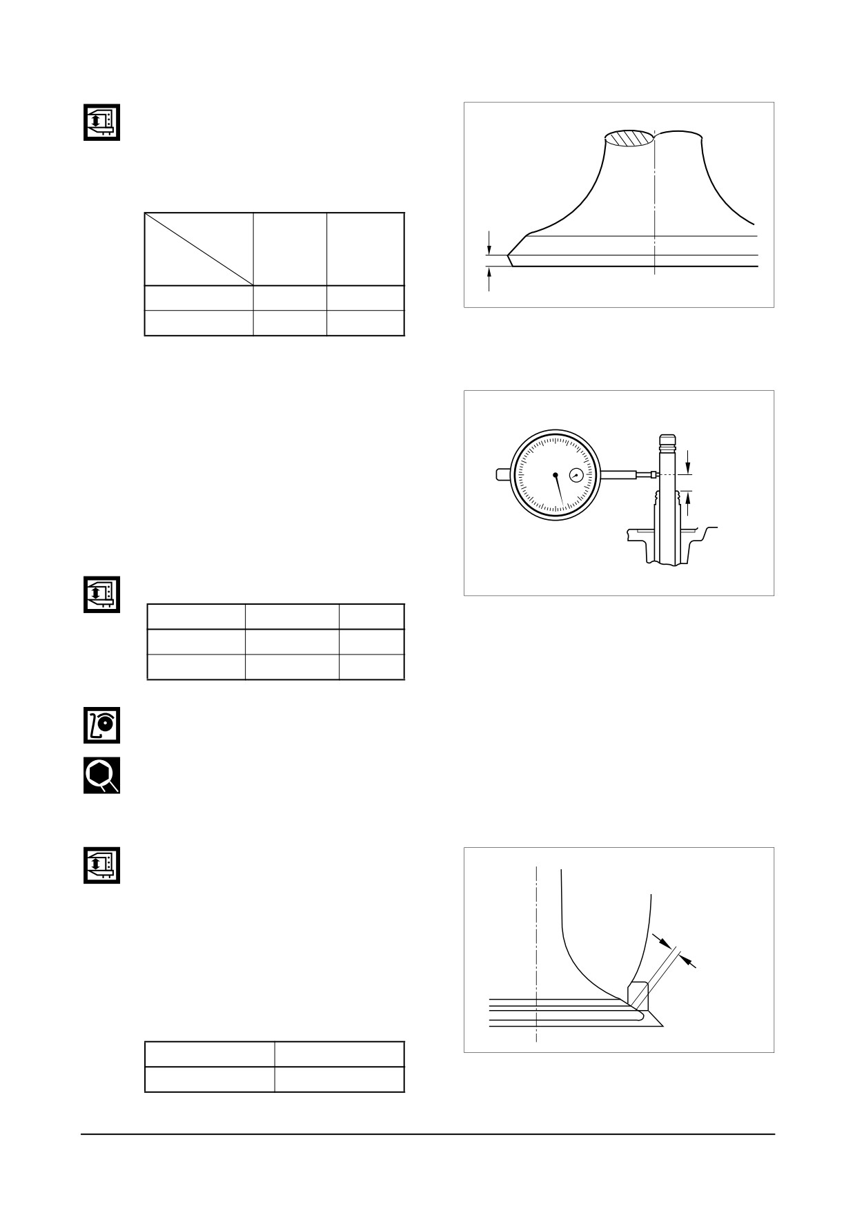
Measure the valve head thickness,
and replace the valve if the mea-
sured value is beyond the limit.
(mm)
Dimension
Standard
Limit
Description
Intake valve
1.5
1 or less
EFM2037I
Exhaust valve
1.5
0.9 or less
2)
Valve guide
● Install the valve into the valve guide
and measure the clearance between
them by valve movement. If the
clearance is excessive, measure the
valve and replace either the valve
Measuring
or the valve guide, whichever worn
position
more.
<Valve stem end play>
EA0M4052
Standard
Limit
Intake valve
0.04 ~ 0.07
0.2
Exhaust valve
0.06 ~ 0.09
0.25
● Install the valve into the cylinder
head valve guide, then check and
see if it is centered with the valve
seat using a special tool.
3)
Valve seat
● Contacting face amount
Measure the contacting
face
between intake valve and exhaust
valve seat for valve seat wear, and
replace if the measured value
exceeds the specified limit.
Contact width
<Valve contact width>
(mm)
EA0M4047
Standard
Limit
0 ~ 0.03
0.55
Disassembly and Reassembly of Major Components
-
75 -
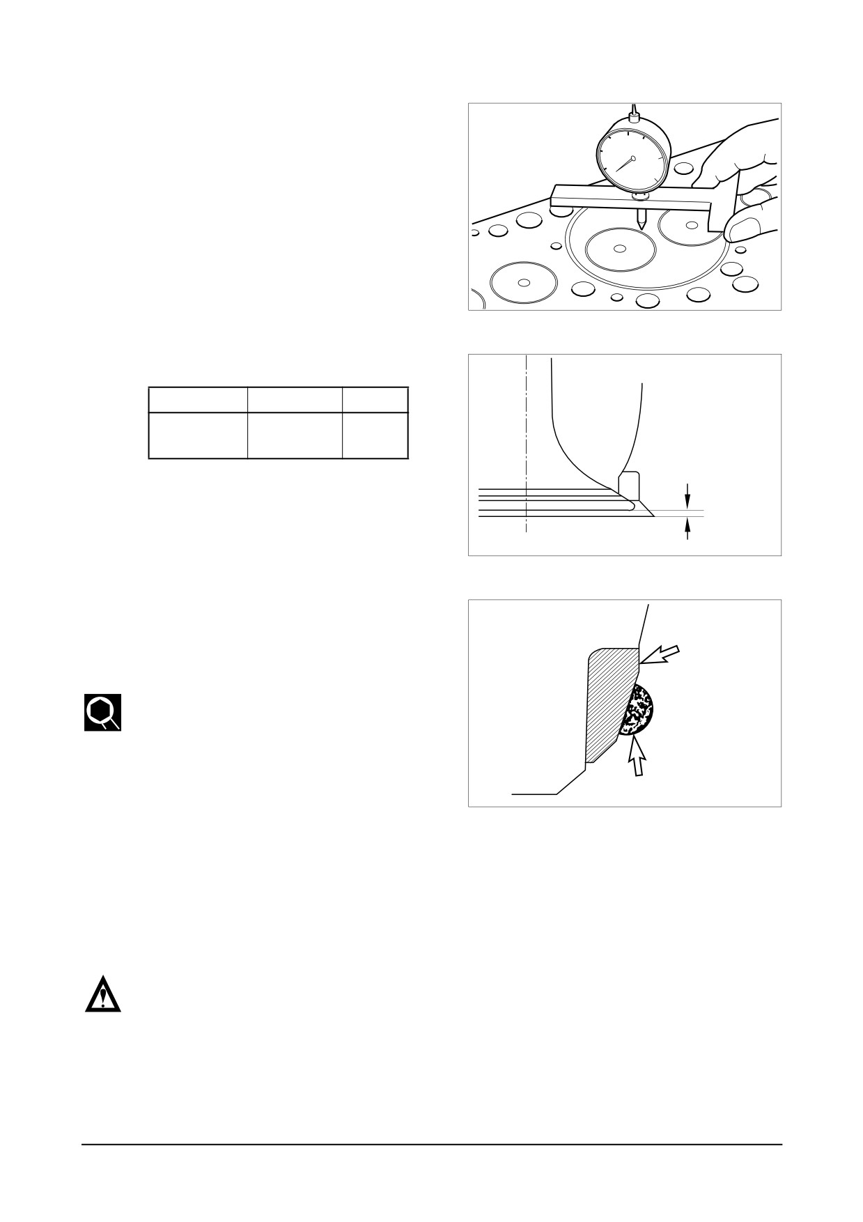
● Install the valve into the valve seat
on the cylinder head, and check the
amount of depression of the valve
from the lower portion of the cylin-
der head using a dial gauge.
EDM2032P
<Valve depression>
(mm)
Standard
Limit
Intake &
0 ~ 0.3
0.55
Exhaust
Depression
If the amount of depression is beyond
the specified limit, replace the valve seat.
EA0M4046
● For removal of the valve seat, apply
arc welding work to two points of
Valve seat
valve seat insert, and pull out the
valve seat insert with inner extractor.
● For assembling of a new valve seat,
Cylinder head
by putting it among the dry ices of
an ice box previously for about
2
hours for the cold shrinkage, and
Welding bead
press it in the cylinder head by a
EA3M2032
special tool. (bench press)
● Apply the valve lapping compound
on the valve head seating face and
lap the valve seat by turning it until
it is seated in its position, then wipe
out the lapping compound.
NOTE :
Clean the valve and cylinder head
with light oil or equivalent after the
valve seat finishing is completed,
and make sure that there are no
grinding materials remained.
D
-
76 -
isassembly and Reassembly of Major Components