DENSO COMMON RAIL SYSTEM (CRS). SERVICE MANUAL (2007) - page 3
Operation Section
1-76
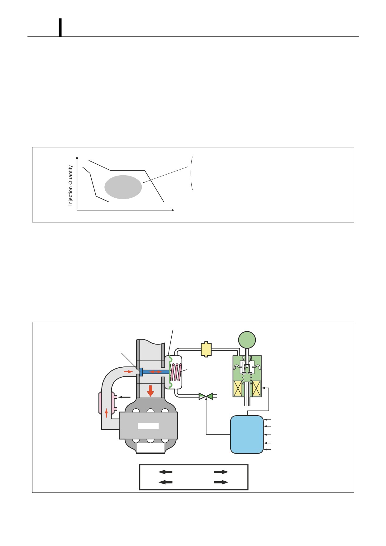
7.2 E-EGR System (Electric-Exhaust Gas Recirculation)
(1) General Description
• The E-EGR system is an electronically controlled EGR system. The EGR system recirculates a portion of the exhaust
gases into the intake manifold in order to lower the combustion chamber temperature and reduce NOx emissions.
However, operation of the EGR system may reduce engine power output and affect drivability. For this reason, in the
E-EGR system, the engine ECU controls the EGR to achieve an optimal EGR amount.
Operation Conditions Example
- This operates in the operation region fulfilling the starting conditions below (one example).
· Engine Operating Conditions
· · · · · Except during engine warm-up and startup,
does not overheat, etc.
· EGR Operating Range
· · · · · · · · For Engine Medium Load
Engine Speed
Q000501E
(2)
Operation
•
After the vacuum pump generates a vacuum, the E-VRV (electric-vacuum regulation valve) regulates the vacuum and
directs it to the diaphragm chamber of the EGR valve. In response to this vacuum, the diaphragm pushes the spring
downward, which determines the opening of the EGR valve and controls the EGR volume.
•
The EGR cooler, which is provided in the EGR passage between the cylinder head and the intake passage, cools the
EGR in order to increase the EGR volume.
•
The EGR cutoff VSV, which opens the diaphragm chamber to the atmosphere when the EGR valve is closed, helps
to improve response.
Diaphragm
Vacuum Pump
Vacuum Damper
EGR Valve
E-VRV
Spring
EGR Shut-Off VSV
Coolant
EGR Cooler
Engine Speed
Engine
Accelerator Opening
Control Unit
Intake Air Pressure And
Atmospheric Pressure
Coolant Temperature
Exhaust
Manifold
Intake Air
Relationship Between Vacuum and EGR Valve Opening
Low
Vacuum
High
Small
EGR Valve Opening
Large
Q000903E
Operation Section
1-77
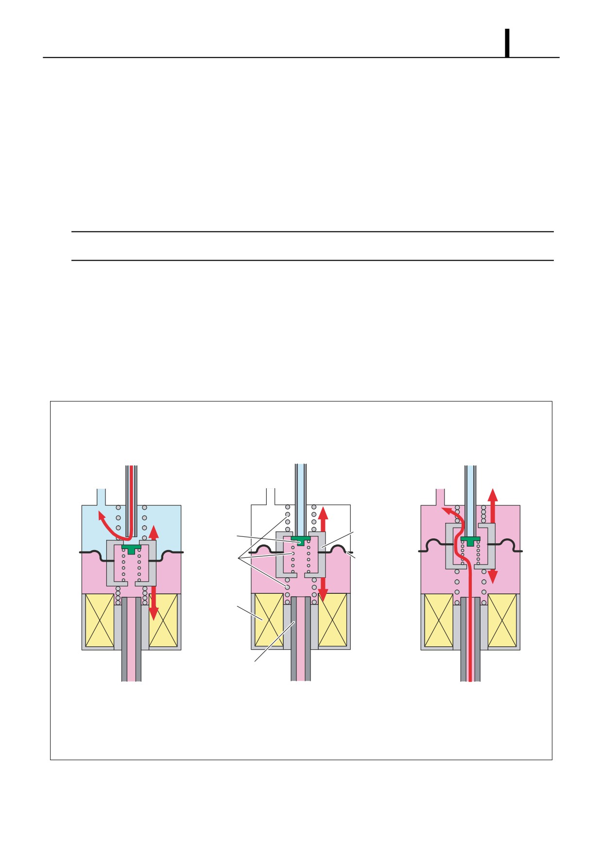
To Increase the EGR Quantity
- The E-VRV duty ratio is controlled*1. In the stable condition shown in the bottom center diagram, an increase in the
current that is applied to the coil causes the attraction force FM in the coil to increase. When this force becomes
greater than the vacuum force FV that acts on the diaphragm, the moving core moves downward. Along with this
movement, the port from the vacuum pump to the upper chamber of the diaphragm opens. Consequently, the out-
put vacuum increases, which causes the EGR valve to open and the EGR volume to increase. Meanwhile, because
"increased output vacuum equals increased FV", the moving core moves upward with the increase in FV. When
FM and FV are equal, the port closes and the forces stabilize. Because the vacuum circuit of the EGR is a closed
loop, it maintains the vacuum in a stabilized state, provided there are no changes in the amperage.
< NOTE >
*1
: The engine ECU outputs sawtooth wave signals with a constant frequency. The value of the current is the effective (average) value of these
signals. For details, see the explanation of the HP3 supply pump and SCV.
To Decrease the EGR Volume
- A decrease in the current that is applied to the coil causes FV to become greater than FM. As a result, the dia-
phragm moves upward. The moving core also moves upward in conjunction with the movement of the diaphragm,
causing the valve that seals the upper and lower diaphragm chambers to open. Consequently, the atmospheric
pressure in the lower chamber enters the upper chamber, thus reducing the output vacuum. This causes the EGR
valve to close and the EGR volume to decrease. Because "decreased output vacuum equals decreased FV", the
moving core moves downward with the decrease in FV. When FM and FV are equal, the port closes and the forces
stabilize.
From Vacuum Pump
To EGR Valve
FV
Moving Core
Valve
Spring
Diaphragm
FM
Coil
Stator Core
Atmosphere
FM > FV
FM < FV
EGR Quantity Increased
EGR Quantity Decreased
Q000904E
Operation Section
1-78
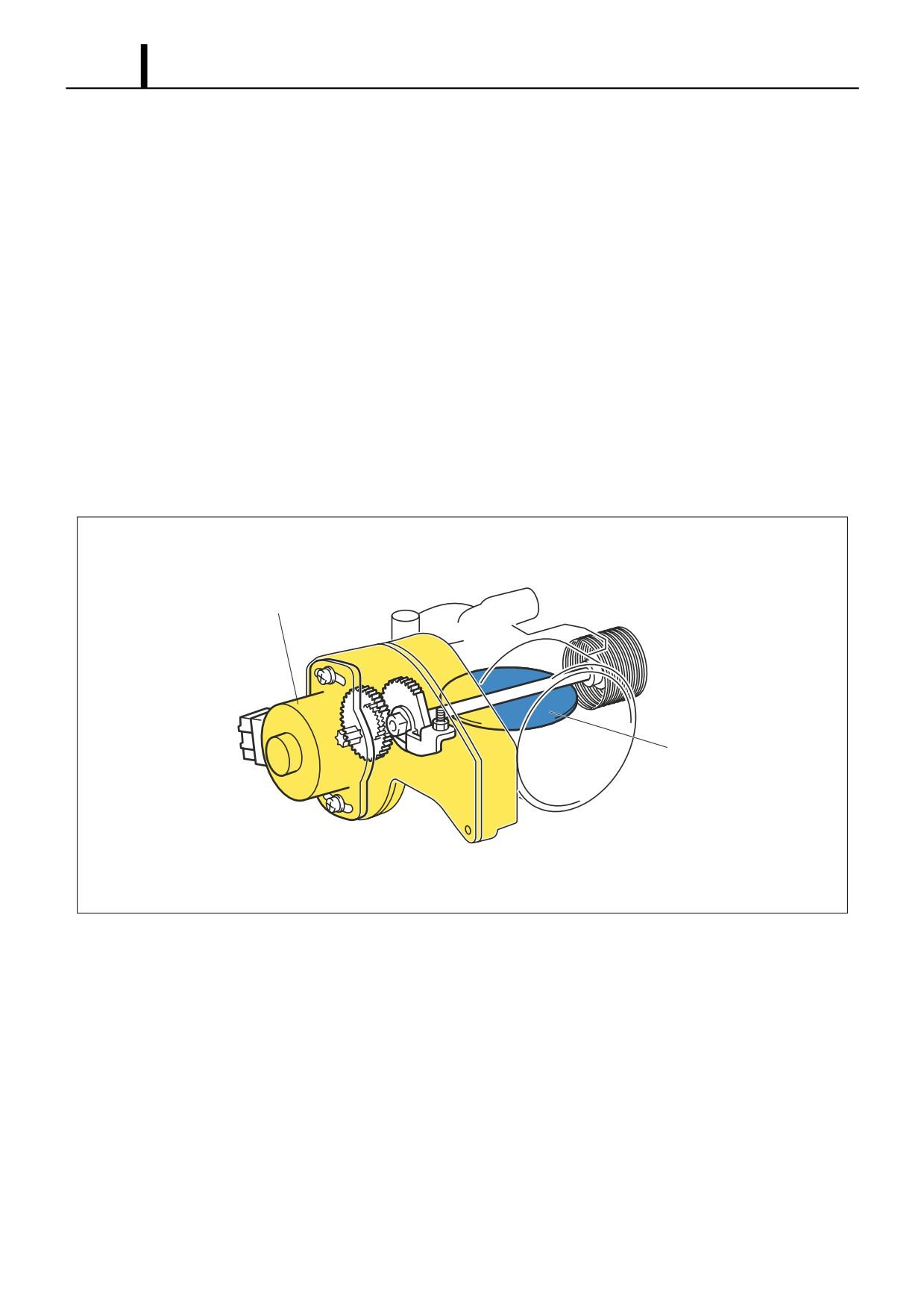
7.3 Electronically Controlled Throttle (Not Made By DENSO)
(1) General Description
• The electronically controlled throttle is located upstream of the EGR valve in the intake manifold. It controls the throttle
valve at an optimal angle to regulate the EGR gas and reduce noise and harmful exhaust gases.
(2) Operation
• Signals from the engine ECU actuate the stepping motor, which regulates the throttle valve opening.
EGR Control
• To further increase the EGR volume when the EGR valve is fully open, the vacuum in the intake manifold can be in-
creased by reducing the throttle valve opening, which restricts the flow of the intake air.
Noise and Exhaust Gas Reduction
• When the engine is being started, the throttle valve opens fully to reduce the emissions of white and black smoke.
• When the engine is being stopped, the throttle valve closes fully to reduce vibration and noise.
• During normal driving, the throttle valve opening is controlled in accordance with the engine conditions, coolant tem-
perature, and atmospheric pressure.
Stepping Motor
Throttle Valve
Q000905E
Operation Section
1-79
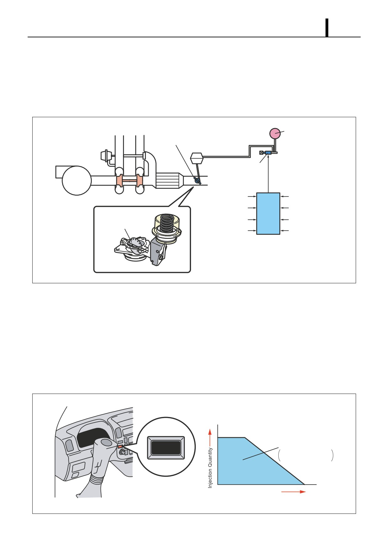
7.4 Exhaust Gas Control System
(1) General Description
• The exhaust gas control system is provided to improve warm-up and heater performance. This system actuates the
exhaust gas control valve VSV, which is attached to the exhaust manifold. It increases the exhaust pressure to in-
crease the exhaust temperature and engine load, in order to improve warm-up and heater performance.
Vacuum Pump
Exhaust Gas
Control Valve
Air Cleaner
VSV
Turbo Pressure
Mass Airflow Meter
Sensor
Cylinder
Coolant Temperature
Recognition Sensor
Sensor
ECU
(TDC (G) Sensor)
Exhaust Gas
EGR Valve Position
Accelerator
Control Valve
Sensor
Position Sensor
Warm-Up Switch
Atmospheric
Pressure Sensor
Q000906E
(2) Operation
• The exhaust gas control system operates when the warm-up switch is ON, and all the conditions listed below have
been met.
Operation Conditions
- The EGR is operating.
- The coolant temperature is below 70°C.
- The ambient temperature is below 5°C.
- A minimum of 10 seconds have elapsed after starting the engine.
- The engine speed and fuel injection quantity are in the state shown in the graph below.
[Exhaust Gas Control System Operating Range]
WARM UP
Operating Range
Extremely Low Torque
or Engine Speed Range
Engine Speed
Q000907E
Operation Section
1-80
7.5 DPF System (Diesel Particulate Filter)
(1) General Description
• This system reduces emissions of PM (particulate matter). In order to collect PM, a DPF cleaner with built-in catalytic
filter is mounted on the center pipe. The collected PM is handled with combustion processing during operation.
(2) System Configuration
Rail
Intake Air
G2 Injector
Intercooler
Pressure Sensor
EGR Cooler
VNT Actuator
EGR Valve
Equilibrium
Actuator
Supply Pump
Exhaust Gas
DPF (with
Temperature Sensor
Oxidation Catalyst)
ECU & EDU
Differential Pressure Sensor
Exhaust Gas Temperature Sensor
Q000908E
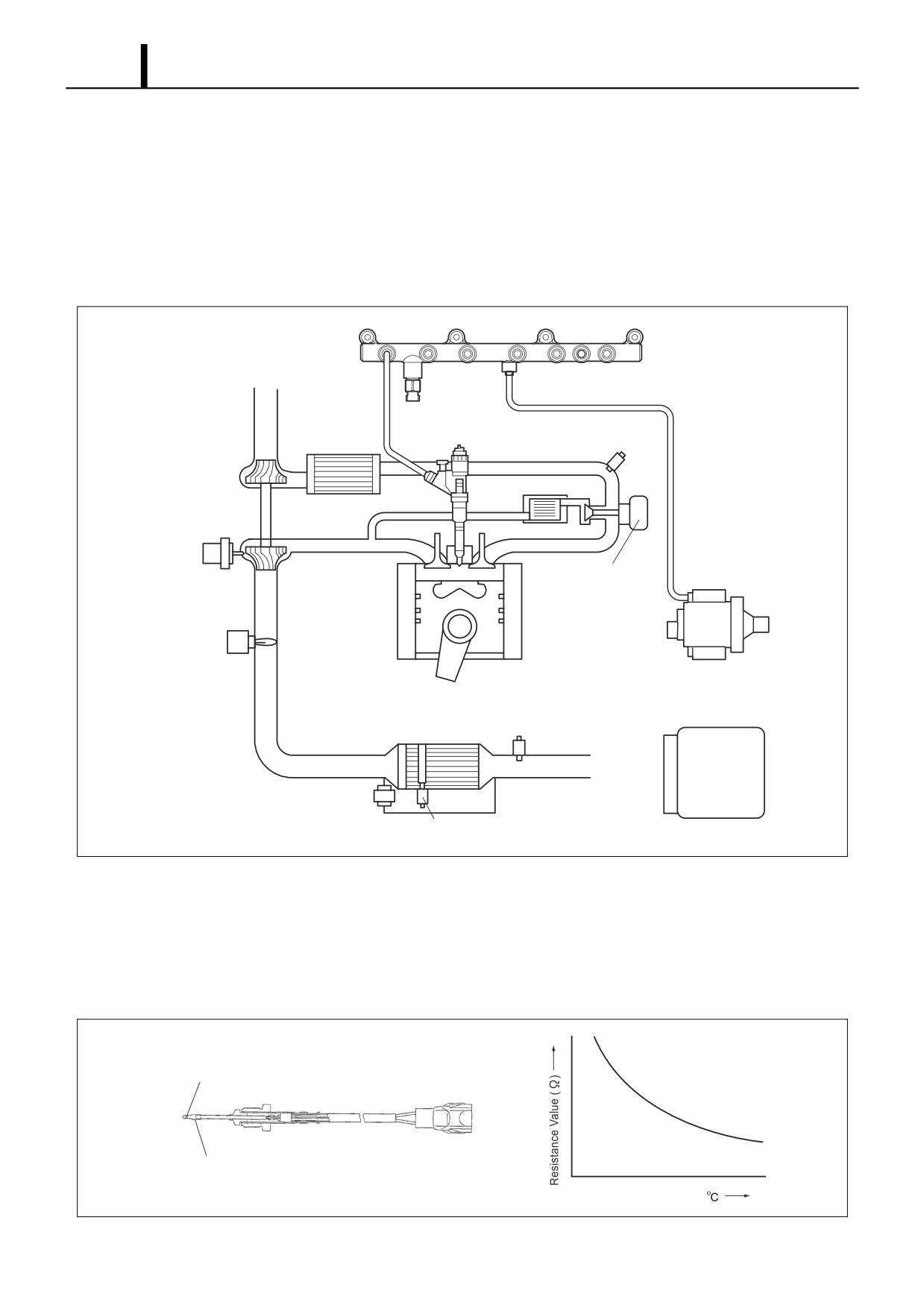
(3) Various Sensors
Exhaust Gas Temperature Sensor
• The exhaust gas temperature sensor is installed to the front and rear of the DPF to detect the temperature in these
positions. The engine ECU controls the exhaust temperature for PM combustion based on the signals from this sen-
sor. The sensor element is a thermistor.
Thermistor Element
Cover
Exhaust Gas Temperature (
)
Q000909E
Operation Section
1-81
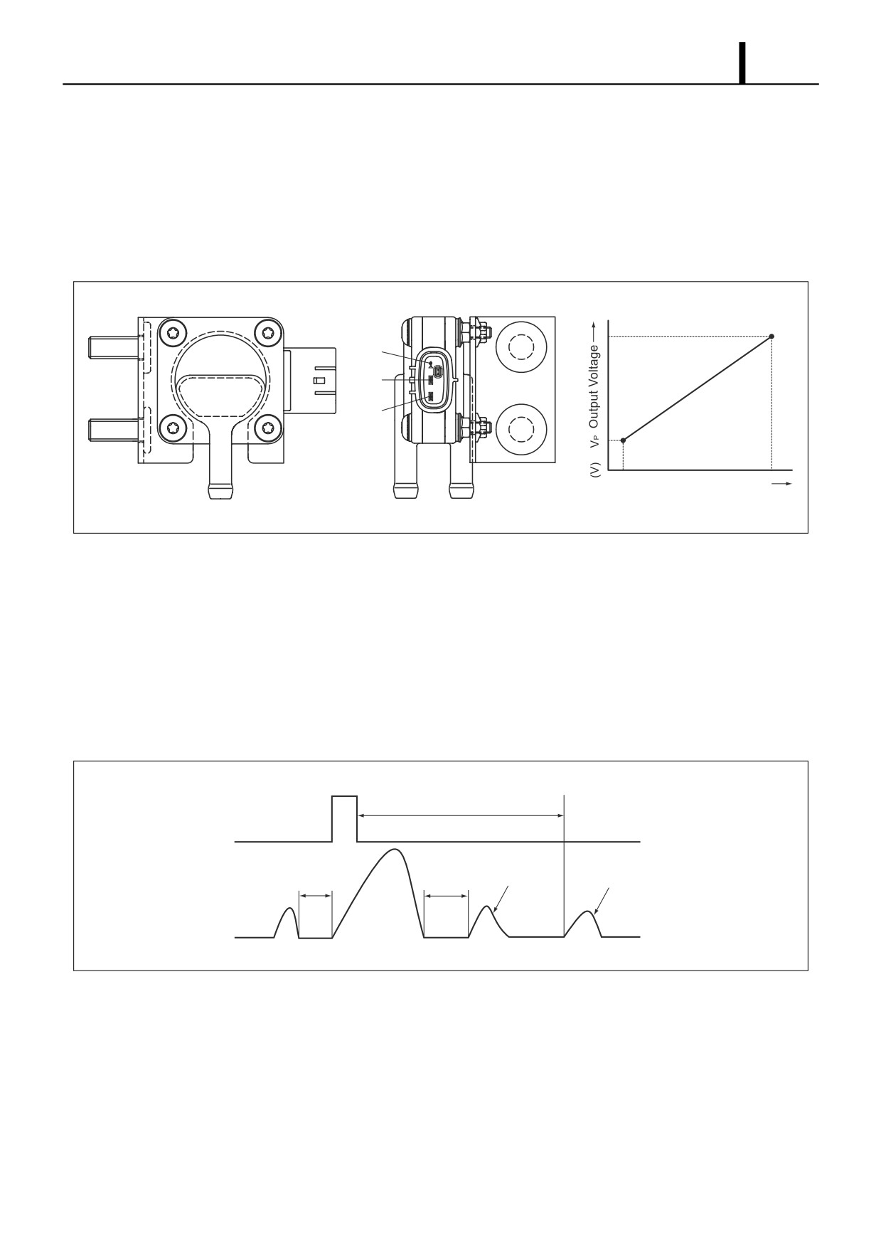
Differential Pressure Sensor
• The differential pressure sensor detects the difference in pressure at the front and rear of the DPF, and outputs a sig-
nal to the engine ECU. The sensor portion is a semiconductor type pressure sensor that utilizes the piezoelectric ef-
fect through a silicon element, and amplifies and outputs the voltage with its IC circuit. When PM is collected and
accumulated in the DPF, the filter clogs and the difference in pressure at the front and rear of the DPF increases.
Therefore, based on the signals from this sensor, the engine ECU judges whether or not to subject PM to combustion
processing.
GND
VP
VC
Pressure (kPa)
Q000910E
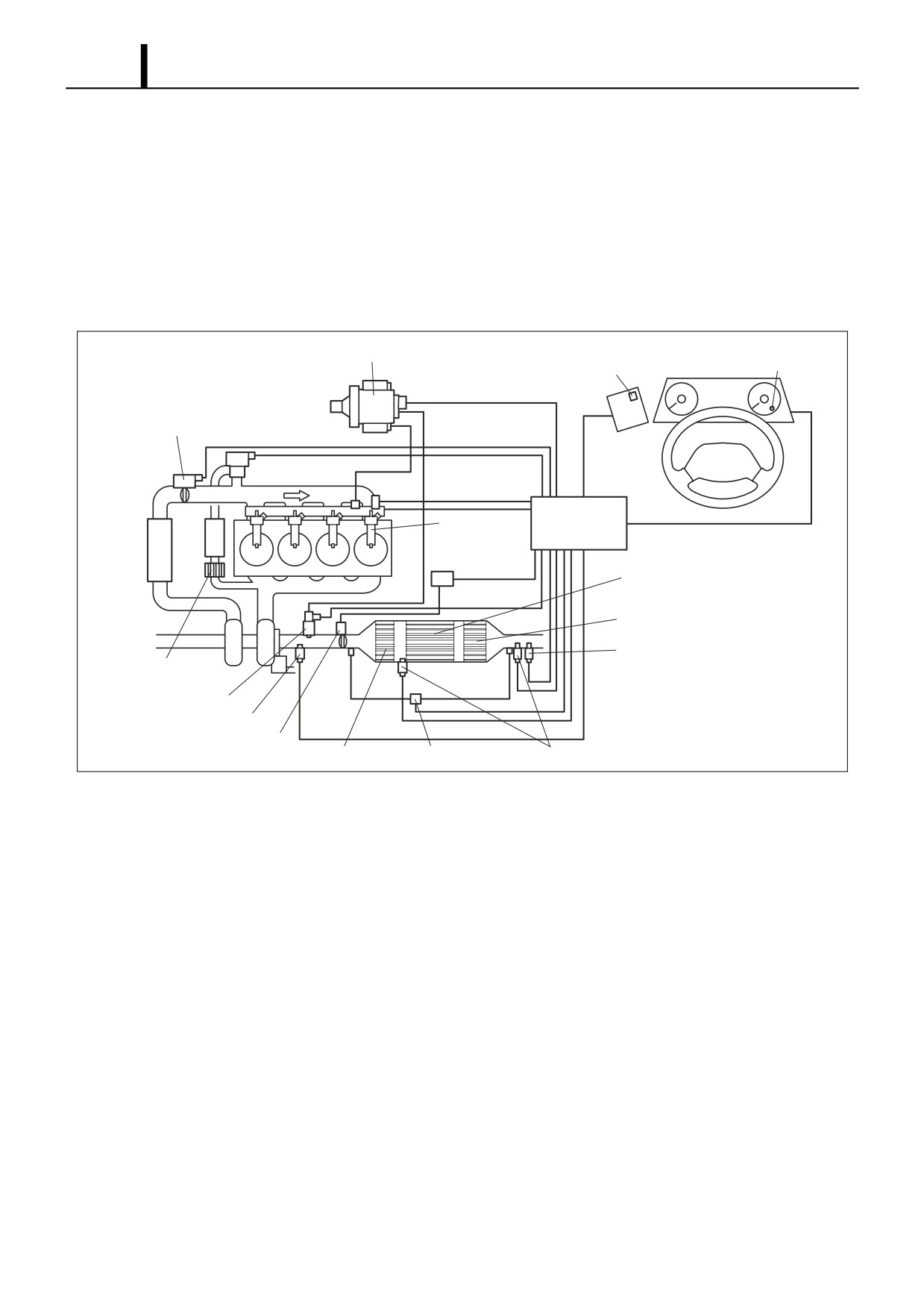
(4) Operation
• By optimizing the injection pattern and controlling the exhaust gas temperature based on the exhaust gas temperature
and the difference in pressure at the front and rear of the DPF, PM is collected, oxidized, and self-combusted. When
the exhaust temperature is low, adding after-injection after the main injection raises the exhaust gas temperature to
approximately 250?C and promotes oxidation of the PM. When the PM is collected and accumulated, the post-injec-
tion is added and HC is added to the catalyst to raise the catalyst temperature to 600?C, which is the self-combustion
temperature for PM. This combusts the accumulated PM in a short time. The engine ECU controls the A, B, and C
times and the injection times.
TDC
A
After-Injection
Post-Injection
B
C
Q000506E
Operation Section
1-82
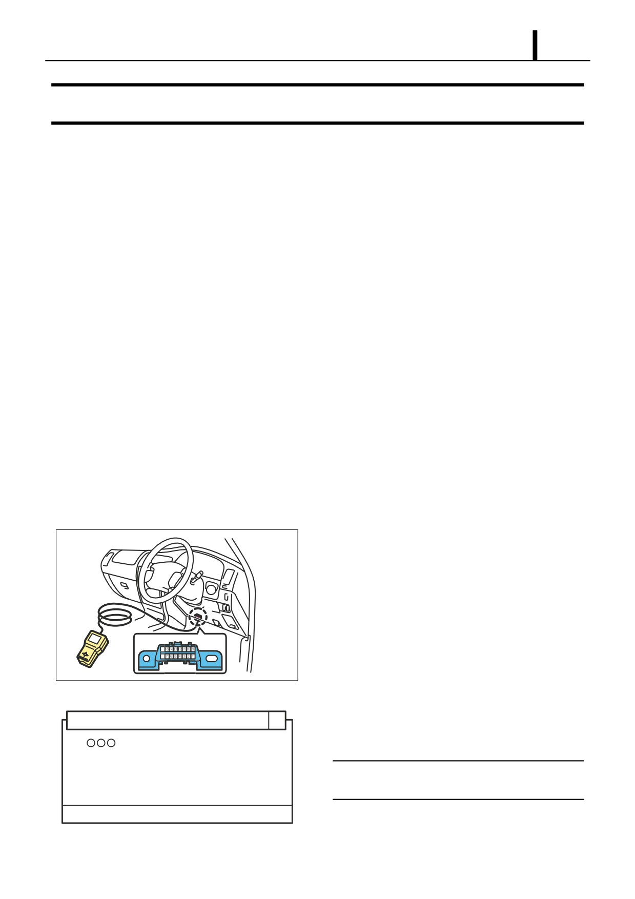
7.6 DPNR SYSTEM (DIESEL PARTICULATE NOx REDUCTION)
(1) General Description
• This system reduces the emissions of PM (particulate matter) and NOx. The DPNR catalyst mounted in the center
pipe collects and regenerates PM and reduces NOx all at the same time. The collected PM is handled with combus-
tion processing during operation.
(2) System Configuration
Exhaust Gas Cleaning
Exhaust Gas Cleaning
Supply Pump
Device Switch
Device Display Lamp
Intake Restriction Valve
Injector
Engine ECU
Exhaust
Retarder VSV
DPNR Catalyst
Oxidation Catalyst
A/F Sensor
Oxidation Catalyst
Before EGR Cooler
Fuel Addition Valve
A/F Sensor
Exhaust Retarder
NSR Differential Pressure Sensor
Exhaust Gas Temperature Sensor
Q000911E
Operation Section
1-83
8. DIAGNOSIS
8.1 Outline Of The Diagnostic Function
z The diagnostic function enables a system to self-diagnose its own malfunctions. If abnormal conditions occur in the sen-
sors or actuators used in the control systems, the respective systems convert the malfunction signals into codes and
transmit them to the engine ECU. The engine ECU records the transmitted malfunction code into memory. Recorded
codes are output at the diagnostics connector on the vehicle. To inform the driver of the malfunction, the engine ECU
causes the MIL (Malfunction Indicator Light) in the meter to illuminate. Accurate troubleshooting can be performed by
way of the DTCs (Diagnostic Trouble Codes) that are output at the diagnostic connector. For details on actual diagnosis
codes, see the vehicle manual. It is necessary to put the vehicle into the state below before starting inspection.
(1) Pre-Inspection Preparation
• Position the shift lever in "N" or "P".
• Turn OFF the air conditioner.
• Verify that the throttle valve is fully closed.
8.2 Diagnosis Inspection Using DST-1
z The DST-1 can be used in both normal and check modes. Compared to the normal mode, the check mode has a higher
sensitivity to detect malfunctions.
z The check mode inspection is performed when normal codes are output in the normal mode, despite the fact that there
may be malfunctions in the sensor signal systems.
(1) Reading DTCs
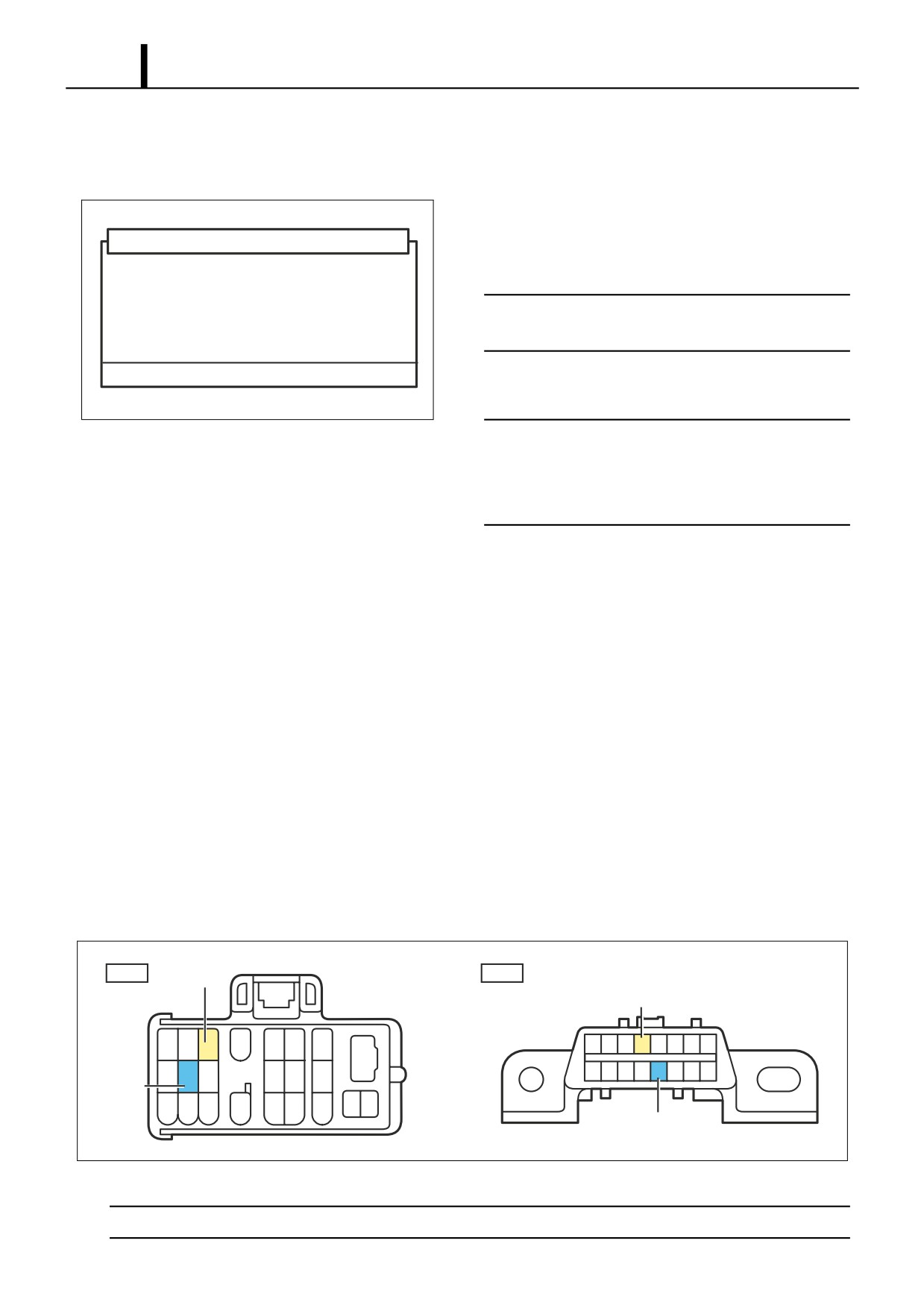
1) DST-1 Connection: Connect the DST-1 to the DLC3 termi-
nal.
DLC3
16
8
Q000914
2) Reading DTCs: Operate in accordance with the instructions
shown on the screen to display the "DTC check" screen. Se-
Diagnostic Trouble Codes (DTC)
lect either the normal or check mode and read the DTC.
1.
· · ·
< NOTE >
If no DTC appears on the screen, there may be a failure
in the engine ECU.
Execute: Execute
Q000915E
Operation Section
1-84
3) Checking the Freeze Frame Data: If the symptom that out-
puts a DTC cannot be duplicated, check the freeze frame
data.
4) Erasing DTCs from memory: Operate in accordance with
the instructions shown on the screen to display the "DTC
DTC (ECD Erasure)
check" screen. Select "Erase DTCs" to erase the DTCs.
This will erase the DTC and freeze frame data.
< NOTE >
Do you wish to proceed?
If it is not possible to erase the DTC, turn the ignition
switch OFF, and repeat the process.
NG : - OK : +
5) Wiring Harness and Connector Open Circuit Check
Q000916E
< NOTE >
If the DTC output during a diagnostic inspection (in the
check mode) has identified the system with a malfunction,
use the method indicated below to narrow down the area
of the malfunction.
• Erasing DTCs from memory: After reading the DTCs in check mode, erase the DTCs from memory.
• Starting the Engine: Select the check mode and start the engine.
• Malfunctioning system check 1: While the engine is running at idle, shake the wiring harness and connectors of the
system that output the malfunction during the diagnosis (check mode) inspection.
• Malfunctioning system check 2: If the MIL (Malfunction Indicator Light) illuminates when the wiring harness and con-
nectors are shaken, there is a poor contact in the wiring harness or connectors in that area.
8.3 Diagnosis Inspection Using The MIL (Malfunction Indicator Light)
z Before reading a DTC, turn the ignition switch ON to make sure the MIL (Malfunction Indicator Light) illuminates.
z Inspections in the check mode cannot be performed.
(1) Reading DTCs
Short circuiting the connector
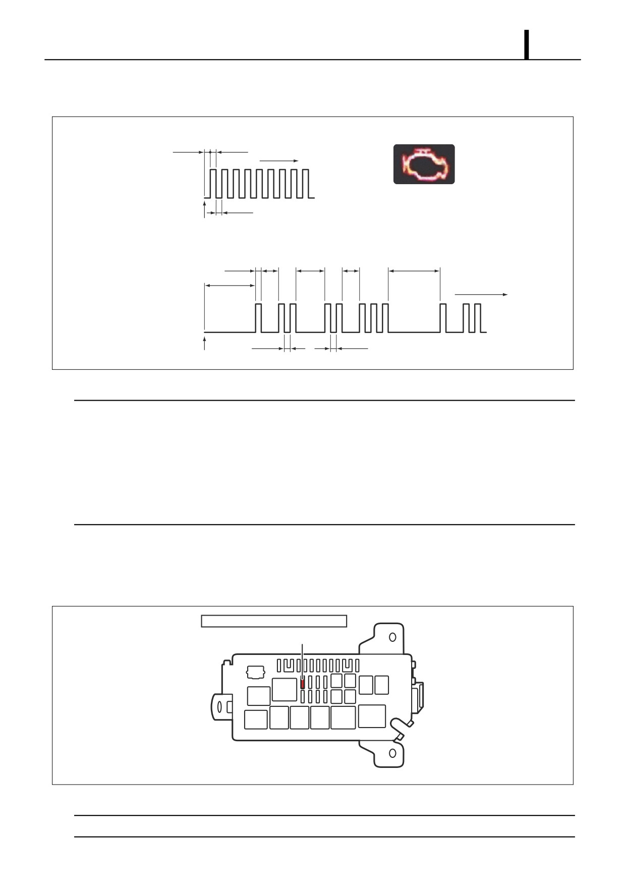
• Using the STT, short circuit between DLC1 terminals 8 (TE1) and 3 (E1) or between DLC3 terminals 13 (TC) and 4
(CG).
DLC1
DLC3
E1
TC
1
2
3
4
5
6
18
16
15 14 13 12
11
10
9
19
8
7
6
5
4
3
2
1
7
8
9
10
11
20
TE1
22
23
12
13
14
15
16
17
21
CG
Q000917E
< CAUTION >
Never connect the wrong terminals of the connectors as this will lead to a malfunction.
Operation Section
1-85
Reading DTCs 1
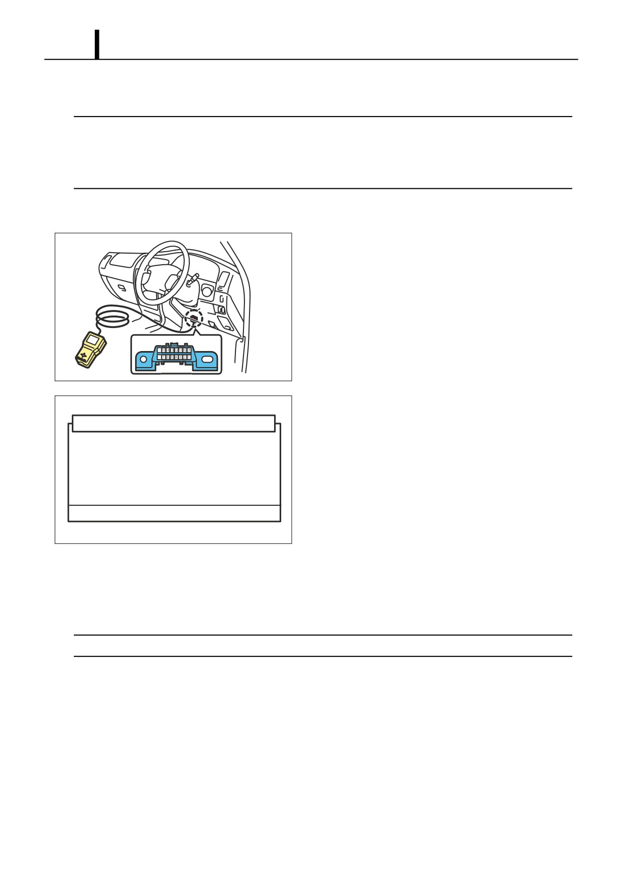
• Turn the ignition switch ON and count the number of times the MIL (Malfunction Indicator Light) blinks
· Normal Operation
0.26sec
0.26sec
Repeat
ON
Malfunction
OFF
Indicator Light
0.26sec
Jump Terminals TE1 and TC
· Malfunction (Codes "12" and "23" are output.)
0.52sec 1.5sec
2.5sec
1.5sec
4.5sec
4.5sec
Repeat Thereafter
ON
OFF
0.52sec
0.52sec
Jump Terminals TE1 and TC
Q000918E
< NOTE >
• If the MIL (Malfunction Indicator Light) does not output a code (the light does not blink), there may be an open circuit in
the TC terminal system or a failure in the engine ECU.
• If the malfunction indicator light is constantly ON, there may be a short (pinching) in the wiring harness or a failure in
the engine ECU.
• If meaningless DTCs are output, there may be a malfunction in the engine ECU.
• If the MIL (Malfunction Indicator Light) illuminates without outputting a DTC while the engine operates at a minimum
speed of 1000rpm, turn the ignition switch OFF once; then resume the inspection.
Reading DTCs 2
• If an abnormal DTC has been output, check it against the DTC list.
Erasing DTCs from memory
• Remove the ECD fuse (15A); after 15 seconds have elapsed, re-install the fuse.
Engine Compartment Relay Block
ECD Fuse (15A)
Q000919E
< CAUTION >
After completing the inspection of the ECD system, erase the DTC memory, and make sure the normal code is output.
Operation Section
1-86
8.4 Throttle Body Function Inspection
< CAUTION >
• Be sure to inspect the function of the throttle body after it has been disassembled and reassembled, or after any of its
components have been removed and reinstalled.
• Verifying Throttle Motor: Verify that the motor generates an operating sound when the ignition switch is turned ON.
Also, verify that there is no interference sound.
(1) Erasing DTCs
1) Connect the DST-1 to the DLC3 connector.
DLC3
16
8
Q000914
2) Operate in accordance with the instructions shown on the
screen to display the "DTC check" screen. Select "Erase
DTC (ECD Erasure)
DTCs" to erase the DTCs.
This will erase the DTC and freeze frame data.
Do you wish to proceed?
NG : - OK : +
Q000916E
(2) Inspection
• Start the engine and make sure the MIL (Malfunction Indicator Light) does not illuminate and the engine speed is with-
in standards when the air conditioner is turned ON and OFF after the engine has warmed up.
< CAUTION >
Make sure no electrical load is applied.
(3) Final Inspection
• After inspecting the throttle body function, drive test the vehicle to confirm that operation is normal.
Operation Section
1-87
9. END OF VOLUME MATERIALS
9.1 Particulate Matter (PM)
z At high concentration levels, this substance is known to affect the respiratory system. It consists of soluble organic mat-
ter such as unburned oil, unburned diesel fuel, and other "soluble organic matter" in the exhaust gases, and insoluble
organic matter such as soot (black smoke) and sulfuric acid gas.
9.2 Common Rail Type Fuel Injection System Development History And
The World’s Manufacturers
z The conventional injection pump faced certain issues such as injection pressure that depended on engine speed, and
limits on the maximum fuel pressure. Other types of injection control such as pilot injection also faced some difficulties.
Addressing these issues in a revolutionary manner, DENSO led the world by introducing a commercial application of
the common rail fuel injection system.
z Two types of common rail fuel injection systems are in use today. One is the common rail system that pressurizes the
fuel and injects it directly into the cylinders. DENSO was the first in the world to introduce a commercial application of
this system. This system, which is undergoing further development, has been adopted in passenger car applications.
Other companies, such as R. Bosch, Siemens, and Delphi also offer their commercial versions of this system today. The
other system is the Hydraulic Electric Unit Injection (HEUI) system, which was developed by Caterpillar in the United
States. This system uses pressurized engine oil to pressurize the fuel by actuating the piston of the nozzle (injector)
through which the pressurized fuel is injected.
Operation Section
1-88
9.3 Higher Injection Pressure, Optimized Injection Rates, Higher Injection
Timing Control Precision, Higher Injection Quantity Control Precision
(1) Higher Injection Pressure
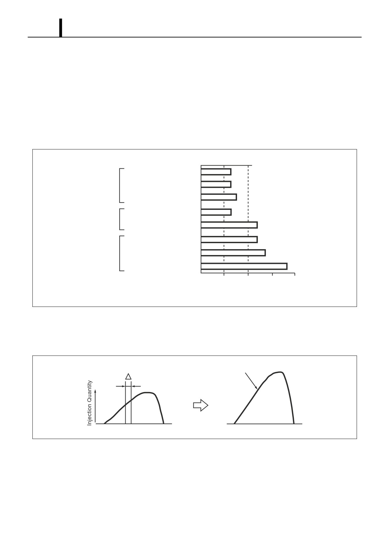
• The fuel that is injected from the nozzle turns into finer particles as the fuel injection pressure increases. This improves
combustion and reduces the amount of smoke contained in the exhaust gases. Initially, the maximum injection pres-
sure of the in-line pump (A type) and the distributor pump (VE type) was 60 MPa. Due to advancement in high-pres-
sure applications, there are some recently developed fuel injection systems that inject fuel at a pressure of 100 MPa
or higher. The second-generation common rail system injects fuel at an extremely high pressure of 180 MPa.
A Type Pump
Mechanical Pump
Distributor Type Pump
NB Type Pump
1 MPa is
ECD V3 Pump
approximately 10.2kgf/cm2
ECD V Series
ECD V4 Pump
120
(1st Generation)
HP0Pump
120
Common Rail Series
HP2Pump
145
(2nd Generation)
HP3,4Pump
185
50
100
150
200
Injection Pressure (MPa)
Q000920E
(2)
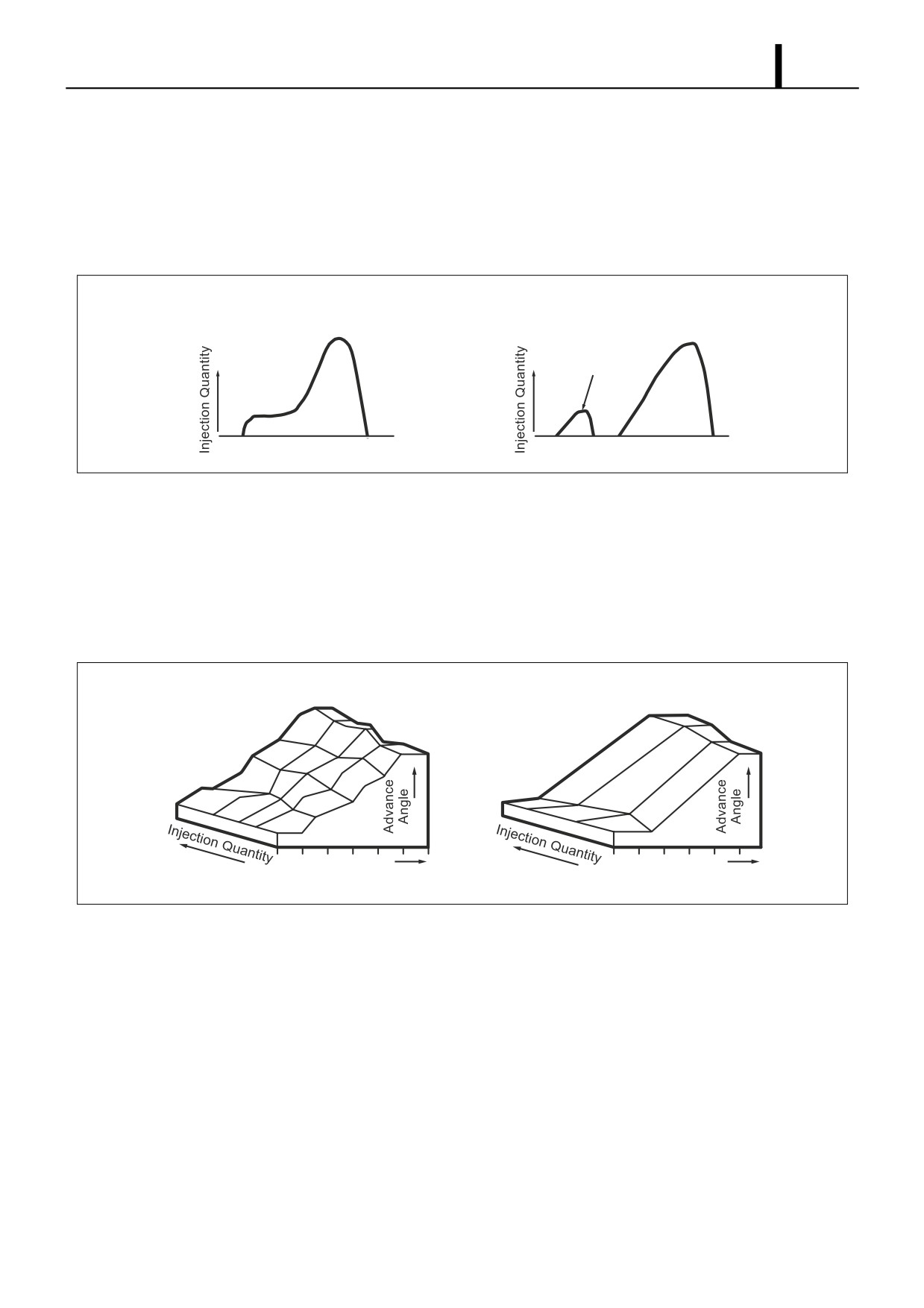
Optimized Injection Rates
•
The injection rate is the ratio of the changes in the fuel quantity that is injected successively from the nozzle within a
given unit of time.
Injection Rate
High Injection Rate
t
Q000921E
Operation Section
1-89
• As the injection pressure increases, the injection rate increases accordingly. The increase in injection rate leads to an
increase in the volume of the air-fuel mixture that is created between the start of injection until ignition (the ignition lag
period). Because this mixture is subsequently combusted at once, it creates noise (diesel knock) and NOx. For this
reason, it is necessary to appropriately control the injection rate by maintaining a low injection rate at the beginning
of injection and supplying a sufficient quantity after the ignition. To meet this need, two-spring nozzles have been
adopted and a pilot injection system has recently been developed.
2-Spring Nozzle
Common Rail System
Injection Rate
Injection Rate Control
Pilot Injection
Q000922E
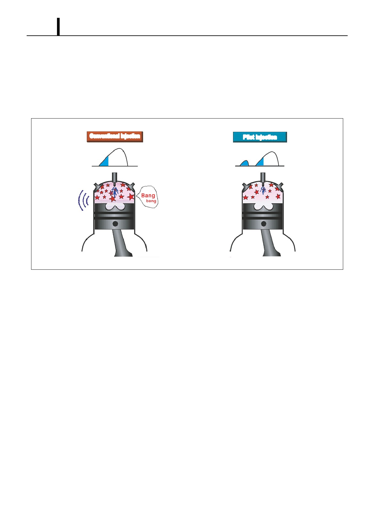
(3) Higher Injection Timing Control Precision
• Reducing exhaust gas emissions and fuel consumption and optimizing the injection timing are important. It is ex-
tremely difficult to achieve the desired exhaust emission reduction levels through methods that adjust the injection
timing according to speed (or centrifugal force), such as the conventional mechanical timer. For this reason, electron-
ically controlled systems have been adopted to freely and precisely control the injection timing in accordance with the
engine characteristics.
Electronic Control Type
Mechanical Timer
Engine Speed
Engine Speed
Q000923E
(4) Higher Injection Quantity Control Precision
• Power output adjustment in a diesel engine is accomplished by regulating the fuel injection quantity. Poor injection
quantity control precision leads to increased exhaust gas emissions, noise, and poor fuel economy. For this reason,
electronically controlled systems have been developed to ensure high precision injection quantity control.
Operation Section
1-90
9.4 Image Of Combustion Chamber Interior
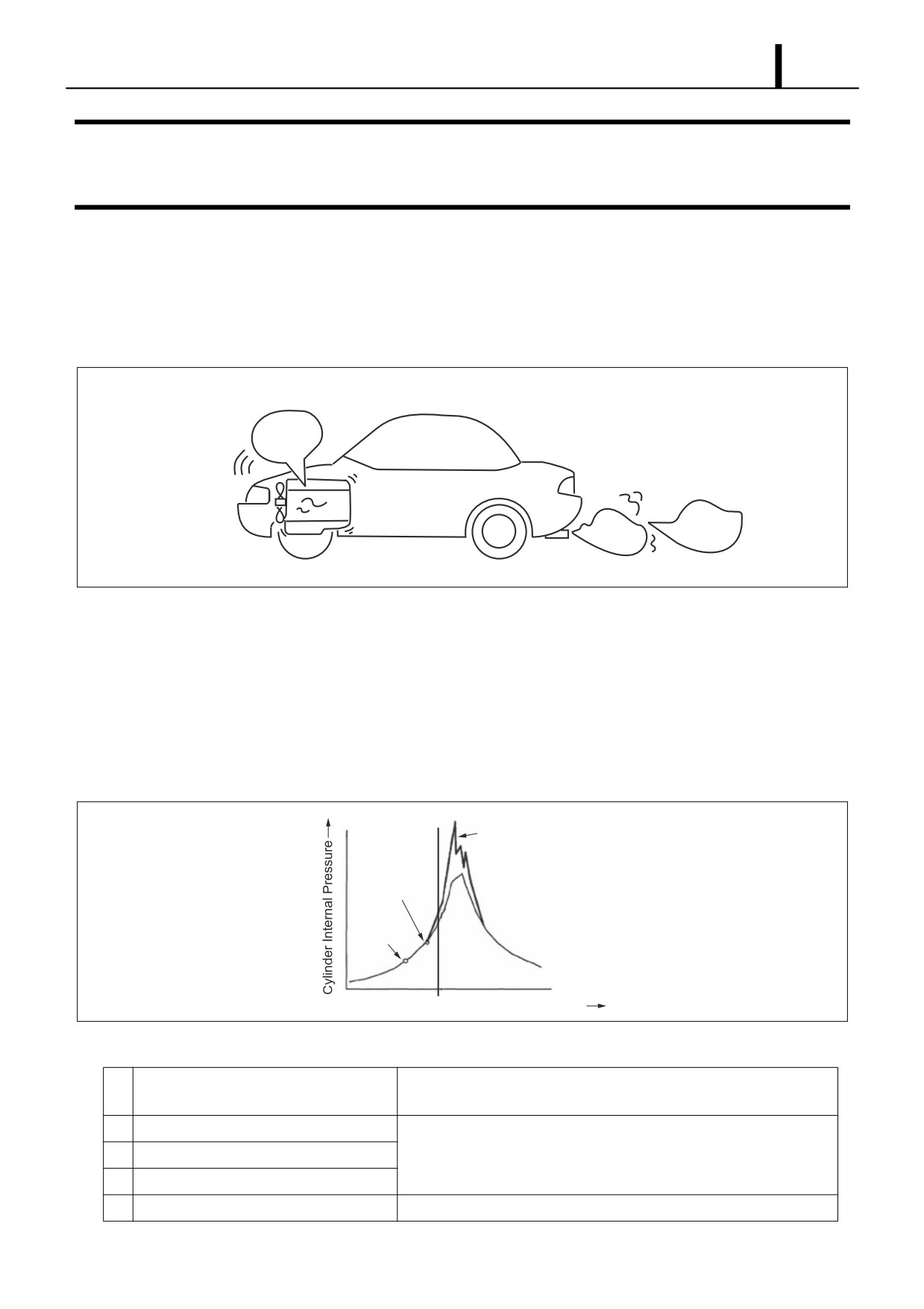
z With conventional injection methods, because an excessive quantity of fuel was injected in the initial period, the explo-
sion pressure rose excessively, leading to the generation of noise such as engine knocking sounds. To improve this
condition through pilot injection, initially only the necessary and adequate quantity of fuel is injected. At the same time,
the combustion chamber temperature is raised, and main injection combustion is assisted while working to prevent
noise and vibration.
Conventional Injection
Pilot Injection
Q000924E
Repair Section
2-91
1. DIESEL ENGINE MALFUNCTIONS AND DIAGNOSTIC METH-
ODS (BASIC KNOWLEDGE)
1.1 Combustion State and Malfunction Cause
z Depending on the state of combustion in a diesel engine, diesel knock as well as the color of the exhaust gas may
change. Subsequently, the cause of engine malfunctions can be ascertained from changes in diesel knock and exhaust
gas color.
Knocking
Sound
White
Black
Smoke
Smoke
Q002310E
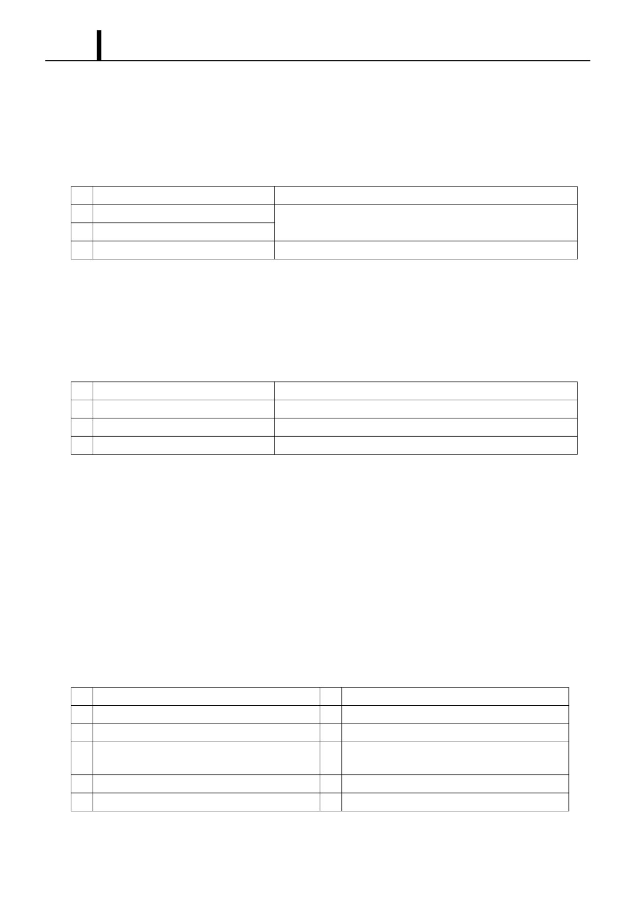
(1) Diesel Knock
• When fuel mixed with air during the ignition lag period (from the time injection begins until the fuel is ignited) reaches
ignition temperature, the mixture is combusted in one burst. The pressure in the combustion chamber at this time rises
as the quantity of the air-fuel mixture increases. If a large amount of air-fuel mixture is created during the ignition lag
period, the pressure in the combustion chamber will rise rapidly. The pressure waves resulting from fuel ignition vi-
brate the cylinder walls and engine components, which generates noise. The generated noise is called "knocking".
To some extent, knocking is unavoidable in engines that use a self-ignition system.
Pressure Increase
Ignition
Start of
Injection
T.D.C. Crankshaft Angle
Q002311E
Cause of Diesel Knocking
A large quantity of air-fuel mixture is created prior to ignition, or the
1
Early Injection Timing
cetane value is high.
2
Cold Engine
3
Intake air temperature is low.
Ignition occurs late without an increase in temperature.
4
Poor Engine Compression
5
Poor Fuel Combustibility
Ignition occurs late (low cetane value.)
Repair Section
2-92
(2) White Smoke
White smoke: Uncombusted fuel that has been vaporized and then discharged.
• White smoke is generated when combustion occurs at a relatively low temperature, resulting in the exhaust of un-
combusted fuel and oil particles. White smoke is most likely to be generated when combustion chamber temperature
is low.
Source of White Smoke
1
Late Injection Timing
Fuel is injected when the piston is in the down stroke.
2
Cold Engine
Ignition occurs late and combustion is prolonged.
3
Poor Fuel Combustibility
4
Rise and Fall of Oil Pressure
Oil undergoes partial thermal breakdown.
(3) Black Smoke
Black smoke: Fuel that has been baked into soot and discharged.
• Black smoke is often referred to as just "smoke". Black smoke is generated when the injected fuel is poor in oxygen.
As the fuel is exposed to high temperatures, thermal breakdown occurs, leaving carbon behind. Black smoke occurs
when the injected fuel quantity is too large, or when the air-fuel mixture is rich due to an insufficient quantity of air.
Source of Black Smoke
1
Large Fuel Injection Quantity
Air-fuel mixture becomes rich.
2
Low Intake Air Quantity
Air quantity is insufficient due to air filter clogging.
3
Poor Fuel Atomization
The ratio of fuel to air worsens.
4
Retarded Fuel Injection Timing
Air-fuel mixing time is insufficient.
1.2 Troubleshooting
Troubleshooting cautions
z Observe the following cautions to avoid decreased engine performance and fuel injector malfunctions.
• Use the designated fuel.
• Avoid water and foreign material intrusion into the fuel tank.
• Periodically check and clean the filter.
• Do not unnecessarily disassemble sealed components.
Troubleshooting notes
z The cause of malfunctions is not necessarily limited to the pump itself, but may also be related to the engine and/or fuel
systems. Further, the majority of malfunctions are the result of user error, and often can often be resolved through simple
checks and maintenance. Avoid any hasty removal of system components.
Basic Check Items
1
Engine Oil
7
Fuel Supply to the Pump
2
Coolant
8
Injector Injection Status
3
Fan Belt
9
Supply Pump Timing Mark
Check for Loose or Disconnected Connectors, and
4
Air Cleaner
10
Modifications
5
Battery and Terminals
11
Idle Speed Status
6
Fuel System Leaks
Repair Section
2-93
2. DIAGNOSIS OVERVIEW
2.1 Diagnostic Work Flow
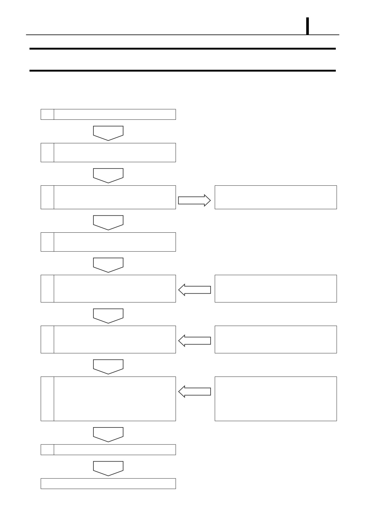
Diagnostic Procedures
1
Receive malfunctioning vehicle
2
Question the user to verify the nature of the
malfunction.
3
Does the malfunction reoccur?
Refer to "Actions for Non-Reoccurring Malfunc-
tions."
4
Verify the malfunction symptom at the actual
vehicle.
5
Use the DST-2 to check for any DTCs.
Proceed with diagnostics while referencing the
DTC chart in the repair manual for the appropri-
ate vehicle.
6
Use the DST-2 "Data Monitor" function to per-
Proceed with diagnostics while referencing the
form checks while monitoring each input and
repair manual for the appropriate vehicle.
output signal.
7
Use the DST-2 active test function to operate
Proceed with diagnostics while referencing the
each output device with the ignition switch in the
repair manual for the appropriate vehicle.
ON position. Check for any abnormalities in
either the electrical circuits or the output
devices.
8
Was the malfunction cleared?
Return to step 3.
Repair Section
2-94
2.2 Inquiries
z Use the Common Rail System (CRS) troubleshooting questionnaire to consult with the customer and adequately grasp
the malfunction symptoms.
< NOTE >
Do not ask random questions. Rather, ask questions that will aid in narrowing down the possible malfunctioning system
while making educated guesses based on the actual symptoms.
Questioning points
z Use the following questions as a basis to fully grasp the malfunction.
• What?: Malfunction symptoms
• When?: Date, time, frequency of occurrence
• Where?: Road conditions
• Under what conditions?: Driving conditions, engine operating conditions, weather
• How?: Impression of how the symptoms occurred.
CRS troubleshooting questionnaire
z When the vehicle is received at the service center, it is necessary to verify the "malfunction symptoms" and the "gener-
ated malfunction data" with the customer. Consult with the customer using the CRS troubleshooting questionnaire. The
troubleshooting questionnaire is necessary for the following reasons.
Reasons
• There are cases when the malfunction symptoms cannot be reproduced at the service center.
• The customer's complaint is not always limited to the malfunction.
• If the person performing repairs is not working from the correct malfunction symptoms, man-hours will be wasted.
• The questionnaire can aid the service center in diagnosing, repairing and verifying repair work.
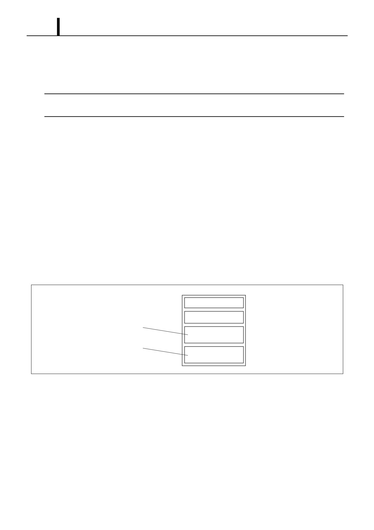
Questioning Results
Inspection Results
Q002315E
Repair Section
2-95
(1) Questionnaire
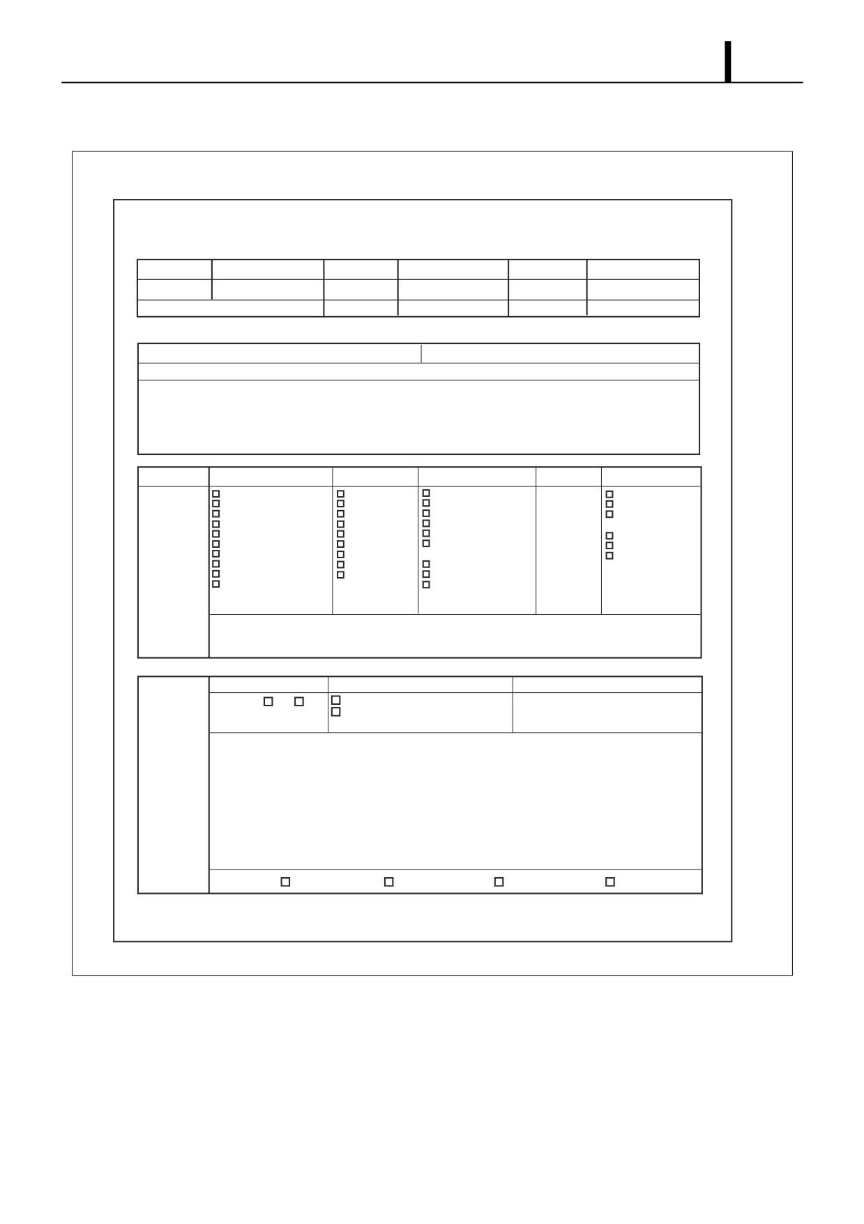
CRS Troubleshooting Questionnaire
Vehicle Model
Receiving Date
Service History
No / Yes (
times)
Frame No.
Date Registered
Registration No.
Occurrence Date
Odometer Reading
Previous Vehicles Driven:
Main Area and Purpose of Use
Other Customer Information
Indications from the Customer
MIL Illumination No / Yes (
)
System Conditions
Driving Conditions
Road Surface
Other
Frequency of Occurrence
Occurrence Speed
During Take-Off
Flat
Accelerator
Normal
(
) km/hr
While Cruising
Uphill
Opening
Only Once
Shift Position
When Accelerating
Downhill
(
) %
Occasionally
(
) Range
When Decelerating
Dry, Sealed road
Outside Air
At Start-Up
When Braking
Wet, Sealed Road
Temperature
(
) Times per Day
Directly after Start-Up
When Turning
Unsealed Road or
(
) oC
(
) Times per Week
Up to (
) Minutes after Start
When Stopped
Rough Road Surface
Weather
(
) Times per Month
Questioning
Up to (
) Minutes into Driving
No Relationship
Snow-Covered or Icy Road
(
)
Results
When Cold
Other (
)
Potholes, Manholes, etc.
When Warm
Other (
)
During Operation
Other (
)
Additional Items
DTC Check
Illuminated
No
Yes
DTC Normal
Fuel Pressure when Engine is Stopped
Abnormal DTC (All Codes)
1 Minute after Turning Engine OFF
Malfunction Details: Time of occurrence, place and driving conditions during reoccurrence.
Inspection
Results
Reoccurrence
Continues to Appear
Occurs Regularly
Occurs Occasionally
Does Not Reoccur
Conditions
After One Occurrence
Q002316E
Repair Section
2-96
2.3 Non-Reoccurring Malfunctions
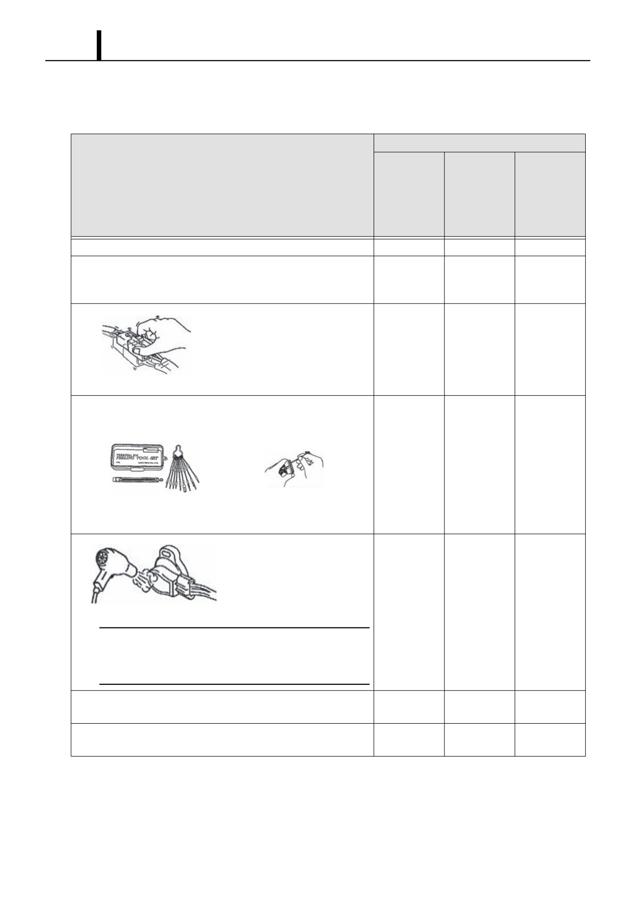
z In cases where the malfunction does not reoccur, perform the actions below to determine the cause of the malfunction.
Malfunction Symptom
Idle Speed,
Fully Dis-
Engine Stall,
Action
Engine will not
charged Bat-
Sputtering,
Start
tery
Poor Acceler-
ation
Verify that there is no DTC stored in the memory.
No
Yes
Yes
Use the questionnaire as a basis to perform a reoccurrence test in
"Reoccurrence" mode. Use this data (engine ECU voltage value, etc.)
Yes
Yes
Yes
to determine the cause of the malfunction.
Assume that an electrical sys-
tem wiring harness or connector
is the cause of the malfunction.
No
Yes
Yes
Shake the wiring by hand to
check whether a malfunction
Q002317
occurs and a DTC is generated.
Assume that an electrical system female connector terminal is the
cause of the malfunction and verify that the connection points are not
defective.
No
Yes
Yes
Recommended Tool: KOWA Precision Handling
Insert the male terminal that
Feeler Gauge Set (KLM-10-20)
matches the shape of the
Depending on the terminal, a matching
female terminal and check
size may not be available
for looseness.
Q002318
Use a dryer to heat the acceler-
ator pedal position sensor and
other electronic components.
Check for changes in the volt-
Q002319
age value (resistance value).
No
No
Yes
< CAUTION >
• Do not exceed 60°C (still touchable by hand) when heating.
• Do not remove the component cases and add heat directly to
electronic parts.
Verify whether malfunction symptoms occur under heavy engine
No
No
Yes
loads (headlights, A/C, wiper, etc. switches ON.)
If any commercial electrical products have been installed, remove
Yes
Yes
Yes
such products and verify whether the malfunction symptoms occur.
Repair Section
2-97
Malfunction Symptom
Idle Speed,
Fully Dis-
Engine Stall,
Action
Engine will not
charged Bat-
Sputtering,
Start
tery
Poor Acceler-
ation
If it is likely that the malfunction
Mist State
occurs in rainy or high-tempera-
ture weather, spray the vehicle
with water and verify whether
Q002320E
the malfunction occurs.
< CAUTION >
No
Yes
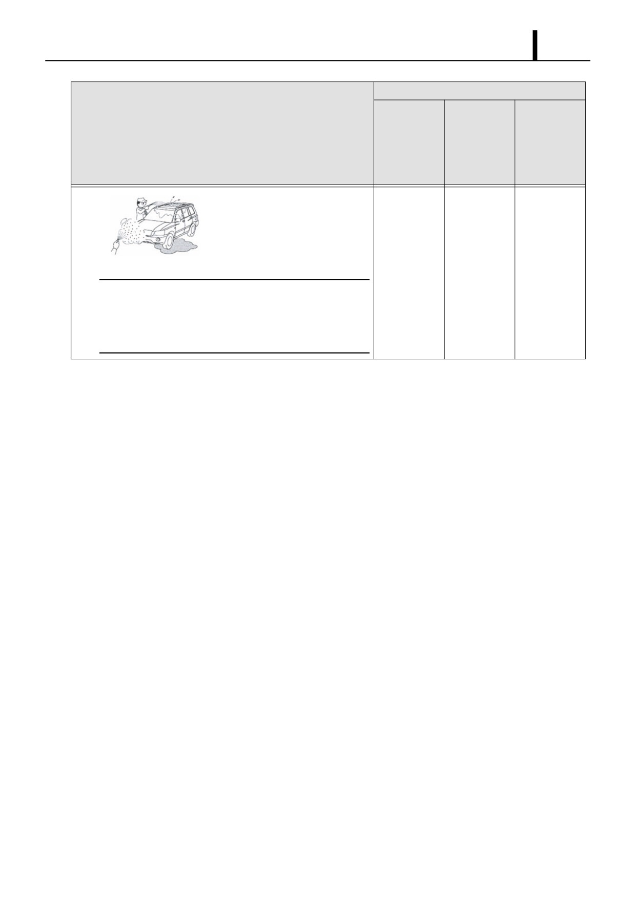
Yes
• Do not spray water directly into the engine compartment.
Spray water in mist form on all surfaces of the radiator to indi-
rectly change temperature and humidity.
• Do not spray water directly on electrical parts.
Repair Section
2-98
3. DTC READING (FOR TOYOTA VEHICLES)
3.1 DST-2
z The DST-2 can check for DTCs in either normal or check mode. In comparison to the normal mode, the check mode
has higher sensitivity in detecting malfunctions. Check mode is used when detection is not possible in normal mode,
regardless of the assumed abnormality.
3.2 DTC Check (Code Reading via the DST-2)
z Connect the DST-2 to the DLC3 connector.
z Operate the DST-2 in accordance with the instructions shown on the display to view the "DTC check" screen. Select
either the normal or check mode to verify the DTC.
3.3 DTC Memory Erasure (via the DST-2)
z To erase DTC codes, follow the instructions on the display to view the "DTC and Freeze Data Erasure" screen.
DTC (ECD Erasure)
This will erase the DTC and freeze frame data.
Do you wish to proceed?
NG : - OK : +
Q000916E
< CAUTION >
• If the DTC cannot be erased, cycle the ignition switch OFF and back ON, and then perform code erasure again.
• Do not use the DST-2 to erase the DTC until the cause of the malfunction is clear.
Repair Section
2-99
4. TROUBLESHOOTING BY SYSTEM
4.1 Intake System Diagnosis
Clogged air cleaner element
1
Clogged air cleaner element
Clean or replace the air cleaner.
NG
OK
2
Check the suction path for leaks.
Repair or replace the malfunctioning compo-
NG
• Suction path joints
nent.
• Suction pipes, hoses
OK
Normal
4.2 Fuel System Diagnosis
Clogged air cleaner element
1
Fuel system check (remaining fuel quantity, fuel
Add fuel or replace components (clean tank.)
NG
properties)
• Check the amount of fuel remaining in the
tank.
• Check the condition of the fuel. Request
engine analysis from a third party as neces-
sary.
- Color (no color, brownish, milky)
- Odor (kerosene, heavy oil, irritating odor)
- Separation of materials
(water, foreign
objects)
- Viscosity
(high/low viscosity, wax consis-
tency)
OK

Repair Section
2-100
2
Fuel tank interior check (modification/additions,
Restore the fuel tank.
NG
position of fuel pipe inlet/outlet, clogging and
holes)
• Check the tank for modifications or additions.
Consult with the user.
- Fuel inlet/outlet position, tank piping
- Foreign material inside the tank, water sep-
aration
- Tank-internal Zn cladding
- Check the tank-internal fuel piping for the
following.
- Inlet/outlet position (below position "E")
- Inlet clogging, bent or deformed piping
(crushed pipe)
- Crushed piping connections
OK
3
Tank-external fuel path conditions
(crushed
Repair or replace the hose.
hose, clogging, air introduction at hose connec-
NG
tion)
• Check the condition of the hose.
- Crushing around bands, over-bending
- Pinched or crushed by other parts
• Air introduction through fuel system connec-
tion points
- Looseness
- Hose deterioration (Verify by hand or visu-
ally that there is no rubber hardening/split-
ting.)
< CAUTION >
Be cautious when vacuum pressure is
present, as air will be drawn into the
hose.
OK
4
Primary filter, sedimentor check
Replace the filter, and drain water from the sedi-
NG
• Check for primary filter clogging and dirt.
mentor.
• Check sedimentor water volume.
OK
5
Looseness at priming attachment point check
Tighten or replace the priming pump.
NG
• Check the following.
- Looseness at the priming attachment point
- Does the piston stick out?
- Fuel leakage (oozing)
OK
Repair Section
2-101
6
Filter (supply pump inlet) clogging
Clean the gauze filter, fuel filter and fuel piping
NG
• Fuel filter
system, or replace the filters.
- Check for fuel delivery from the priming
pump.
• Gauze filter
- Visually check for clogging due to foreign
material.
OK
7
Oil level increase (engine internal leak)
Check the engine.
NG
• V erify whether the oil level increases on the
oil level gauge.
OK
8
High-pressure piping and CRS component
Repair leaking high-pressure piping or replace
NG
(injector supply pump, rail) fuel leaks (engine
leaking parts.
external leak) (Refer to "(2) Fuel leak check".)
• Connect the DST-2 to the diagnostic connec-
tor. Activate the "Fuel Leak Check Function"
within the active test.
• Visually check and specify areas that leak
fuel.
< CAUTION >
In the event of a large fuel leak down-
stream of the flow damper, be aware
that fuel flow will stop and the leak will
cease due to flow damper operation.
OK
Normal
(1) Fuel pressure test procedure
• Connect the DST-2 to the vehicle-side test connector.
- With the vehicle idling, verify the rail pressure displayed on the DST-2.
System selection screen: Rail a ECU Data Monitor
Item Name (Abbrevi-
Explanation
Check Conditions
Reference Value
Items of Importance
ated)
During an Abnormal-
ity
Rail Pressure (RP)
• Displays the fuel
Following
engine
Fuel pressure in the
PCR1, PCR2 signals
pressure in the rail.
warm-up, when the
rail is displayed within
(rail assembly)
• Display range:
0
engine is rotating
a range of 30 MPa to
MPa to 255 MPa
160 MPa.
Repair Section
2-102
(2) Fuel leak check
• Connect the DST-2 to the vehicle-side test connector.
• With the vehicle idling, perform the active test by following the instructions on the DST-2 display.
System selection screen: TCCS a Active Test
Item Name
Description
Control Conditions
High-Pressure Fuel System Check
Raise engine speed to 2000 rpm, and
• Following engine warm-up, when
then use the active test to place the
the engine is at idle speed
fuel inside the rail under high pres-
• The vehicle speed sensor is operat-
sure.
ing normally, and speed is 0 km/h.
< CAUTION >
Engine speed cannot be
raised by stepping on the
accelerator pedal.
• Verify that there are no fuel system leaks during the active test (when fuel pressure is being applied to the rail.)
4.3 Basics of Electrical/Electronic Circuit Checks
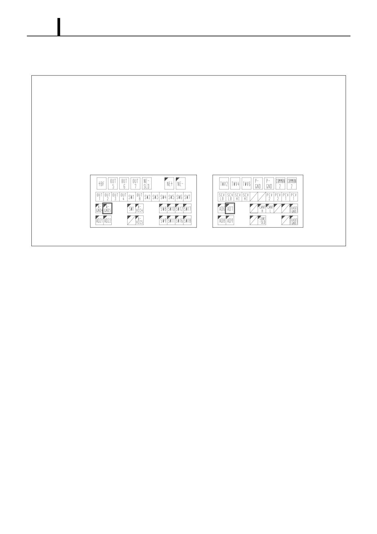
(1) ECU terminal voltage and waveform measurements
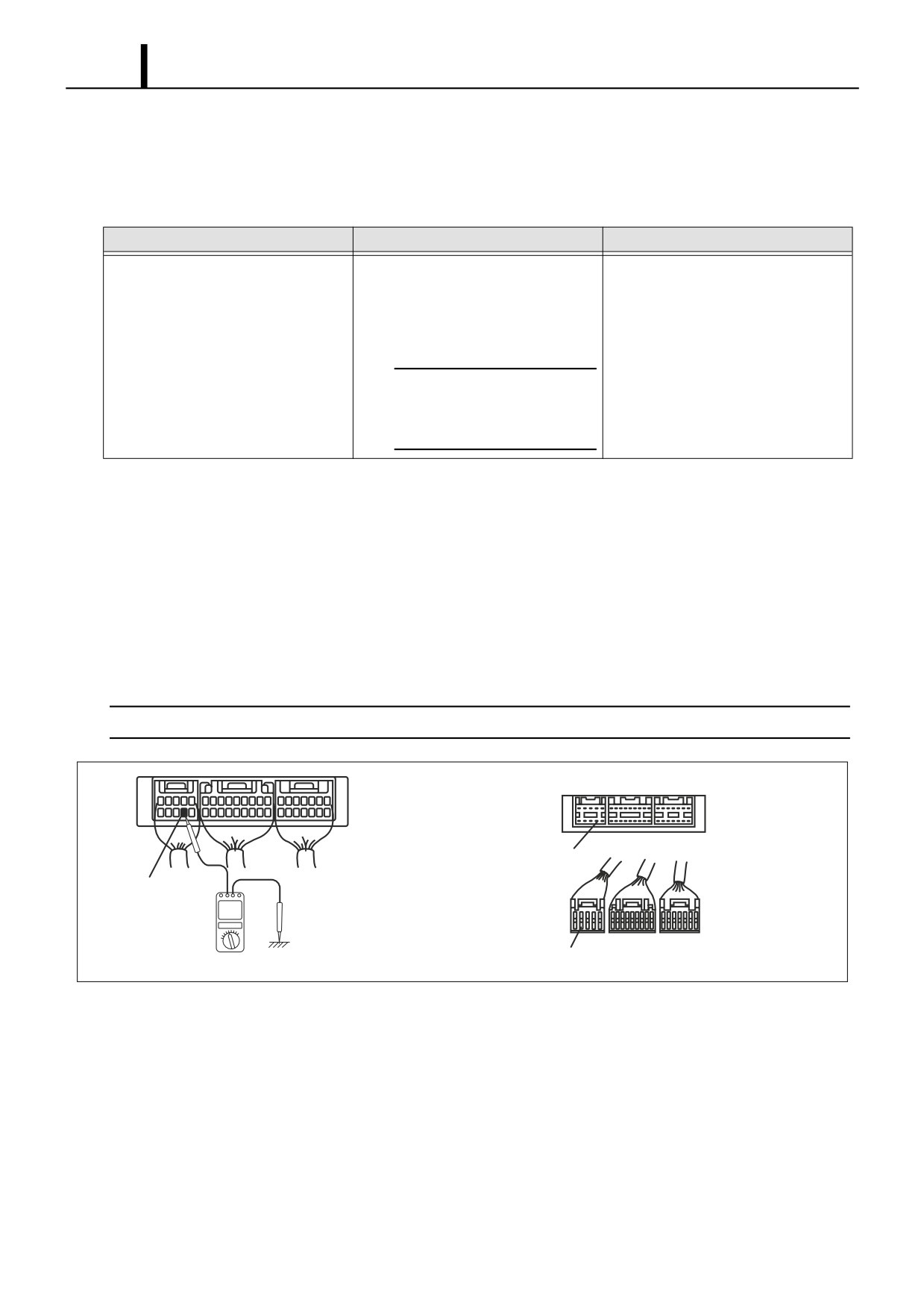
• When measuring the voltage and resistance of each terminal, insert the multimeter probe into the rear side of the
wiring harness connector. If connectors are too small for the probe to be inserted easily, insert a fine metal wire into
the rear of the connector and touch the wire to the probe.
< NOTE >
The number of each terminal can be seen from the rear side of the wiring harness.
Engine ECU Side
Ground
Ground
Wiring Harness
Side
Ground
Q002326E
Repair Section
2-103
(2) Open circuit check
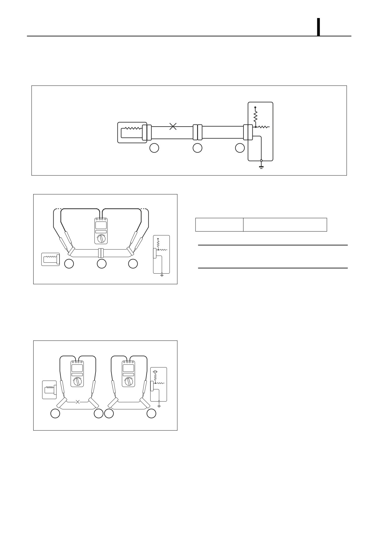
• When dealing with a wiring harness open circuit like that depicted in diagram 1, check continuity and/or voltage to
determine the location of the open circuit.
Diagram 1
Engine ECU
Open
Sensor
Circuit
1
1
1
1
2
2
2
2
C
B
A
Q002327E
Continuity Check
1)
Remove connectors "A" and "C", and then measure resis-
Diagram 2
tance between the two.
Engine
Standard Value
1Ω or less
ECU
< NOTE >
1
1
Sensor
Measure resistance while gently shaking the wiring har-
2
2
2
ness up and down, and side-to-side.
C
B
A
Q002328E
2)
As shown in diagram 2, there is no continuity (open circuit)
between terminal 1 of connector "A" and terminal 1 of con-
nector "C". However, there is continuity between terminal 2
of connector "A" and terminal 2 of connector "C". Therefore,
there is an open circuit between terminal 1 of connector "A"
and terminal 1 of connector "C".
3)
Remove connector "B" and measure the connector resis-
Diagram 3
tance.
Engine
ECU
4)
As shown in diagram 3, there is continuity between terminal
Sensor
1 of connector "A" and terminal 1 of connector "B1". Howev-
er, there is no continuity (open circuit) between terminal 1 of
connector "B2" and terminal 1 of connector "C". Therefore,
1
1
1
1
2
2
2
2
there is an open circuit between terminal 1 of connector "B2"
C
B2 B1
A
and terminal 1 of connector "C".
Q002329E
Repair Section
2-104
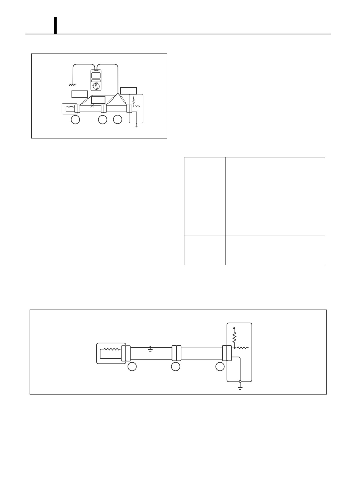
Voltage Check
1)
For the circuit that applies voltage to the ECU connector ter-
Diagram 4
minals, check for an open circuit by performing a voltage
check.
2)
As shown in diagram 4, with all connectors connected, mea-
5 V
0 V
sure the voltage for the ECU 5 V output terminal between
Sensor
5 V
the body ground and terminal 1 of connector "A". Next mea-
1
1
1
2
2
2
sure voltage for terminal 1 of connector "B" and terminal 1 of
C
B
A
connector "C" in the same fashion.
Q002330E
3)
The faulty circuit and measurement results are shown be-
low.
• Voltage between terminal 1 of con-
nector "A" and the body ground is 5
V.
• Voltage between terminal 1 of con-
Measurement
nector "B" and the body ground is 5
Results
V.
• Voltage between terminal 1 of con-
nector "C" and the body ground is 0
V.
There is an open circuit in the wiring
Faulty Item
harness between terminal 1 of connec-
tor "B" and terminal 1 of connector "C".
(3)
Short circuit check
•
As shown in diagram 5, if there is a short in the wiring harness ground, perform a "Ground Continuity Check" to de-
termine the cause of the short.
Diagram 5
Engine ECU
Short
Sensor
Circuit
%
$
#
Q002331E
Repair Section
2-105
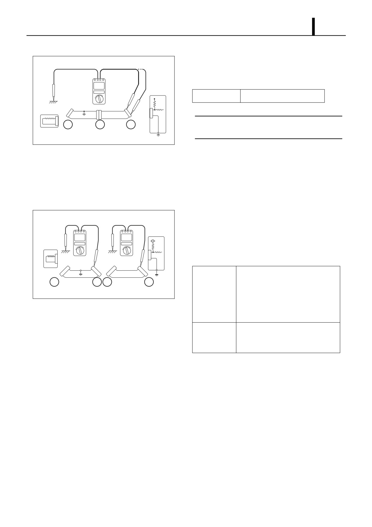
Ground Continuity Check
1)
Remove connector "A" and connector "C", and then mea-
Diagram 6
sure the resistance respectively between terminals 1 and 2
of connector "A" and ground.
Engine
ECU
Standard Value
1Ω or less
1
1
1
Sensor
< NOTE >
2
2
2
Measure resistance while gently shaking the wiring har-
C
B
A
ness up and down, and side-to-side.
Q002332E
2)
As shown in diagram 6, there is continuity between terminal
1 of connector "A" and the body ground (short circuit). How-
ever, there is no continuity between terminal 2 of connector
"A" and the body ground. Therefore, there is a short circuit
between terminal 1 of connector "A" and terminal 1 of con-
nector "C".
3)
Remove connector "B" and measure the resistance be-
Diagram 7
tween terminal 1 of connector "A" and the body ground, and
Engine
ECU
between terminal 1 of connector "B2" and the body ground.
Sensor
4)
The faulty circuit and measurement results are shown be-
low.
1
1
1
1
Measurement
• There is no continuity between termi-
2
2
2
2
C
B2
B1
A
Results
nal 1 of connector "A" and the body
ground.
Q002333E
• There is continuity between terminal
1 of connector "B2" and the body
ground.
Faulty Item
There is a short circuit between terminal
1 of connector "B2" and terminal 1 of
connector "C".
Repair Section
2-106
(4) Connector connection fault verification method
• Simultaneously perform the data monitor and connector voltage measurements.
Ex.) Coolant temperature sensor
1. Read the "Coolant Temperature Output Voltage" value using the DST-2 data monitor.
2. Measure the voltage directly from the corresponding ECU terminal.
If "1" is unsatisfactory and "2" is satisfactory, the connector connection is judged as faulty.
Since some malfunctions only occur intermittently, measure voltage while pulling and shaking the
wires in order to try to get the malfunction to reoccur.
Voltage Measurement
No.2 - 34P
No.5 - 31P
35
41
137
143
62
69
162
167
Q002334E
Repair Section
2-107
5. TROUBLESHOOTING
5.1 Troubleshooting According to Malfunction Symptom (for TOYOTA Ve-
hicles)
(1) Malfunction Indicator Lamp (MIL) is lit.
Description
The check engine warning light is lit when the engine is running, or before the engine is started.
Possible Cause
The DTC is recorded in the engine ECU.
Clogged air cleaner element
1
Connect the DST-2 and read the DTC.
Inspect the check engine warning light circuit.
NG
OK
Troubleshoot the corresponding DTC.
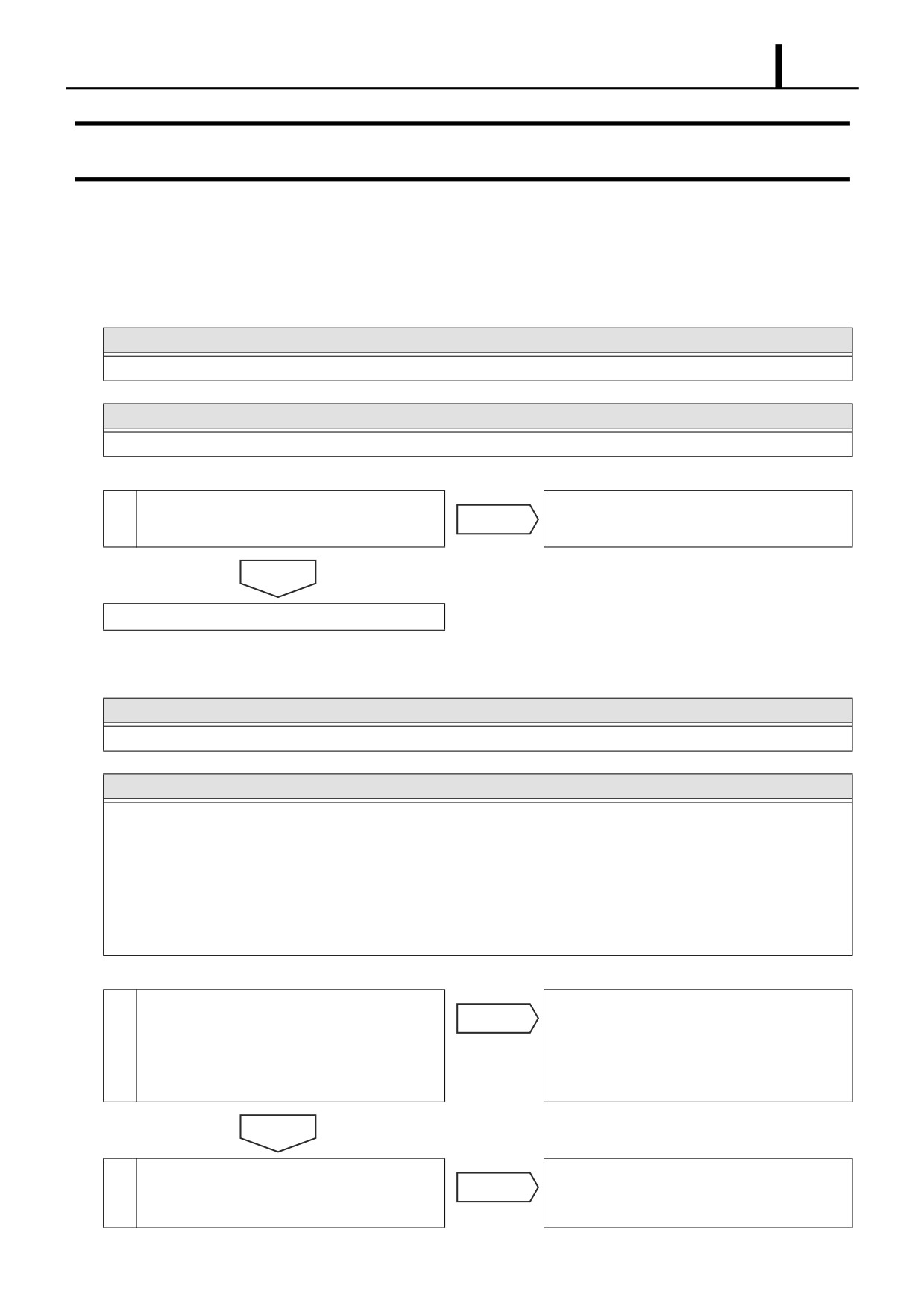
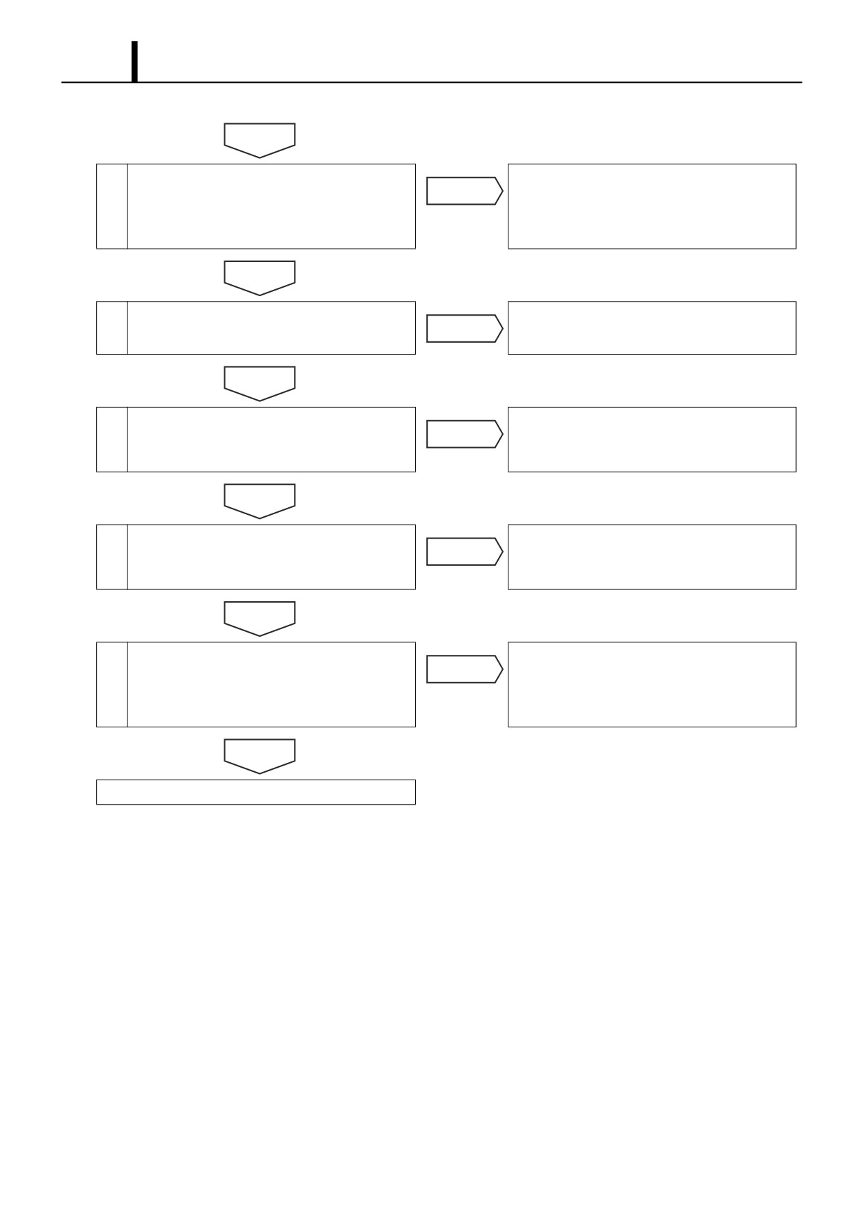
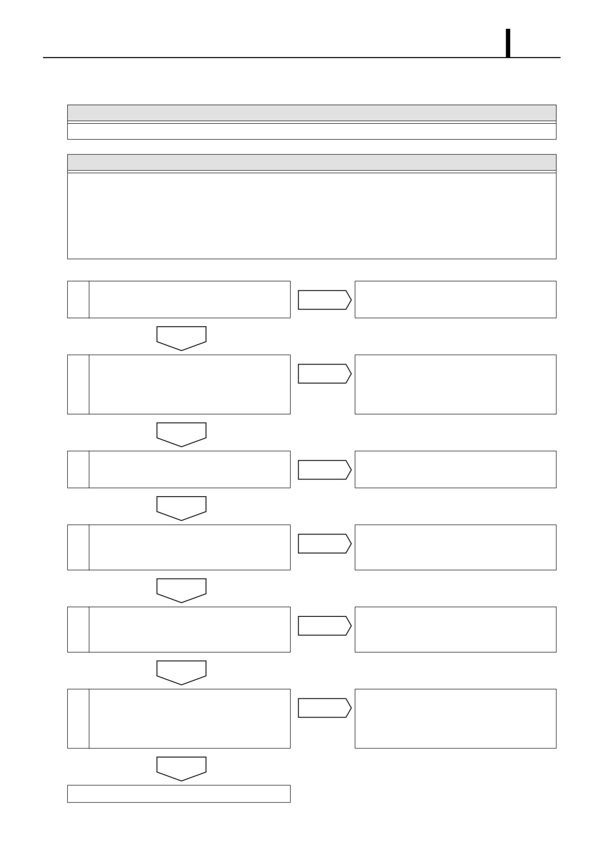
(2) The engine is hard to start.
Description
The starter turns at normal speed, but the engine takes too long to start.
Possible Cause
• Start signal circuit
• Glow control system
• Crankshaft position sensor
• Engine ECU power supply circuit
• Injector
• Supply pump
• Cylinder recognition sensor
Clogged air cleaner element
1
Use the DST-2 to verify whether the coolant
Repair the glow control system. (Refer to the
temperature is at the glow system operating
NG
glow control system check procedure issued by
temperature. In addition, verify whether battery
the vehicle manufacturer.)
voltage is being supplied to the glow plugs at
the designated times.
OK
2
Use the DST-2 to monitor engine speed while
Check the crankshaft position sensor. (Refer to
NG
cranking the engine. Verify whether engine
the crankshaft position sensor check procedure
speed is being correctly output.
issued by the vehicle manufacturer.)
Repair Section
2-108
OK
3
Verify the output waveform of the cylinder rec-
Repair or replace the cylinder recognition sen-
NG
ognition sensor. (Refer to the cylinder recogni-
sor and/or the corresponding circuit.
tion sensor check procedure issued by the
vehicle manufacturer.)
OK
4
Check each injector. (Refer to the injector check
Repair or replace the injector and/or the corre-
NG
procedure issued by the vehicle manufacturer.)
sponding circuit.
OK
5
Verify whether there is a start signal when
Repair the start signal circuit.
NG
cranking the engine by checking the engine
ECU start signal terminal.
OK
6
Check the engine ECU power supply. (Refer to
Repair the engine ECU power supply.
NG
the engine ECU power supply circuit diagram
issued by the vehicle manufacturer.)
OK
7
Check the supply pump and the supply pump
Repair or replace the supply pump and drive cir-
NG
drive circuit. (Refer to the supply pump drive cir-
cuit.
cuit diagram issued by the vehicle manufac-
turer.)
OK
Troubleshooting complete
Repair Section
2-109
(3) The engine stalls when idling.
Description
The engine stalls after starting or when idling.
Possible Cause
• Crankshaft position sensor
• Engine ECU power supply circuit
• Injector
• Supply pump
• Engine cooling system
• Start signal circuit
Clogged air cleaner element
1
Verify that the engine is not overheated.
Repair the engine cooling system.
NG
OK
2
Check the crankshaft position sensor output
Repair or replace the crankshaft position sensor
NG
waveform. (Refer to the crankshaft position sen-
and/or the corresponding circuit.
sor check procedure issued by the vehicle man-
ufacturer.)
OK
3
Check each injector. (Refer to the injector check
Repair or replace the injector and/or the corre-
NG
procedure issued by the vehicle manufacturer.)
sponding circuit.
OK
4
Verify whether there is a start signal when
Repair the start signal circuit.
cranking the engine by checking the engine
NG
ECU start signal terminal.
OK
5
Check the engine ECU power supply. (Refer to
Repair the engine ECU power supply.
the engine ECU power supply circuit diagram
NG
issued by the vehicle manufacturer.)
OK
6
Check the supply pump and the supply pump
Repair or replace the supply pump and drive cir-
NG
drive circuit. (Refer to the supply pump drive cir-
cuit.
cuit diagram issued by the vehicle manufac-
turer.)
OK
Troubleshooting complete
Repair Section
2-110
(4) The engine cranks normally, but does not start.
Description
The engine is cranked at the normal speed, but does not start.
Possible Cause
• Crankshaft position sensor
• Engine ECU power supply circuit
• Injector
• Supply pump
• Start signal circuit
Clogged air cleaner element
1
Use the DST-2 to verify whether the coolant
Repair the glow control system. (Refer to the
temperature is at the glow system operating
NG
glow control system check procedure issued by
temperature. In addition, verify whether battery
the vehicle manufacturer.)
voltage is being supplied to the glow plugs at
the designated times.
OK
2
Monitor engine speed while cranking the
Check the crankshaft position sensor. (Refer to
NG
engine. Verify whether engine speed is being
the crankshaft position sensor check procedure
correctly output.
issued by the vehicle manufacturer.)
OK
3
Verify whether there is a start signal when
Repair the start signal circuit.
NG
cranking the engine by checking the engine
ECU start signal terminal.
OK
4
Check the engine ECU power supply. (Refer to
Repair the engine ECU power supply.
NG
the engine ECU power supply circuit diagram
issued by the vehicle manufacturer.)
OK
5
Check each injector. (Refer to the injector check
Repair or replace the injector and/or the corre-
NG
procedure issued by the vehicle manufacturer.)
sponding circuit.
OK
6
Check the supply pump and the supply pump
Repair or replace the supply pump and drive cir-
NG
drive circuit. (Refer to the supply pump drive cir-
cuit.
cuit diagram issued by the vehicle manufac-
turer.)
OK
Troubleshooting complete
Repair Section
2-111
(5) Idle instability following engine start
Description
Idle speed after starting the engine is abnormal.
Possible Cause
• Injector
• Supply pump
• Fuel filter
• Engine ECU
• Rail pressure sensor
Clogged air cleaner element
1
Check each injector. (Refer to the injector check
Repair or replace the injector and/or the corre-
procedure issued by the vehicle manufacturer.)
NG
sponding circuit.
OK
2
Check the fuel filter.
Replace the fuel filter.
NG
OK
3
Check the supply pump and the supply pump
Repair or replace the supply pump and drive cir-
NG
drive circuit. (Refer to the supply pump drive cir-
cuit.
cuit diagram issued by the vehicle manufac-
turer.)
OK
4
Check the rail pressure sensor and the corre-
Repair or replace the rail pressure sensor and
NG
sponding circuit. (Refer to the rail pressure sen-
the corresponding circuit.
sor check procedure issued by the vehicle
manufacturer.)
OK
Troubleshooting complete
Repair Section
2-112
(6) The engine returns to idle speed too slowly, or does not return at all.
Description
The time required for the engine to return to idle speed is longer than normal, or the engine does not return to idle
speed.
Possible Cause
• Accelerator position sensor
• Injector
• Supply pump
Clogged air cleaner element
1
Perform the accelerator pedal position sensor
Repair or replace the accelerator position sen-
NG
function check. (Refer to the accelerator posi-
sor and/or the corresponding circuit.
tion pedal sensor check procedure issued by
the vehicle manufacturer.)
OK
2
Check each injector. (Refer to the injector check
Repair or replace the injector and/or the corre-
procedure issued by the vehicle manufacturer.)
NG
sponding circuit.
OK
3
Check the supply pump and the supply pump
Repair or replace the supply pump and drive cir-
NG
drive circuit. (Refer to the supply pump drive cir-
cuit.
cuit diagram issued by the vehicle manufac-
turer.)
OK
Troubleshooting complete
Repair Section
2-113
(7) Rough idle
Description
Idle speed fluctuates, causing the engine to vibrate.
Possible Cause
• Engine cooling system
• Crankshaft position sensor
• Engine
• Supply pump
• Injector
Clogged air cleaner element
1
Check parts that may be a source of abnormal
Repair the engine.
engine vibration.
NG
OK
2
Check each injector. (Refer to the injector check
Repair or replace the injector and/or the corre-
NG
procedure issued by the vehicle manufacturer.)
sponding circuit.
OK
3
Verify that the engine is not overheated.
Repair the engine cooling system.
NG
OK
4
Check the crankshaft position sensor. (Refer to
Repair or replace the crankshaft position sensor
NG
the crankshaft position sensor check procedure
and/or the corresponding circuit.
issued by the vehicle manufacturer.)
OK
5
Check the supply pump and the supply pump
Repair or replace the supply pump and drive cir-
NG
drive circuit. (Refer to the supply pump drive cir-
cuit.
cuit diagram issued by the vehicle manufac-
turer.)
OK
Troubleshooting complete
Repair Section
2-114
(8) The engine stalls when decelerating.
Description
The engine suddenly stops when decelerating.
Possible Cause
• Engine cooling system
• Crankshaft position sensor
• Engine ECU power supply circuit
• Supply pump
• Injector
• Start signal circuit
Clogged air cleaner element
1
Verify that the engine is not overheated.
Repair the engine cooling system.
NG
OK
2
Check the crankshaft position sensor. (Refer to
Repair or replace the crankshaft position sensor
NG
the crankshaft position sensor check procedure
and/or the corresponding circuit.
issued by the vehicle manufacturer.)
OK
3
Check each injector. (Refer to the injector check
Repair or replace the injector and/or the corre-
NG
procedure issued by the vehicle manufacturer.)
sponding circuit.
OK
4
Verify whether there is a start signal when
Repair the start signal circuit.
NG
cranking the engine by checking the engine
ECU start signal terminal.
OK
5
Check the engine ECU power supply. (Refer to
Repair the engine ECU power supply.
NG
the engine ECU power supply circuit diagram
issued by the vehicle manufacturer.)
OK
6
Check the supply pump and the supply pump
Repair or replace the supply pump and drive cir-
drive circuit. (Refer to the supply pump drive cir-
NG
cuit.
cuit diagram issued by the vehicle manufac-
turer.)
OK
Troubleshooting complete
Repair Section
2-115
(9) Poor engine output, poor acceleration
Description
Deficient engine performance.
Possible Cause
• EGR system
• Injector
• Mass Air Flow (MAF) meter
• Crankshaft position sensor
• Accelerator position sensor
• Boost pressure sensor
• Supply pump
• Start signal circuit
• Air cleaner, duct
Clogged air cleaner element
1
Check for air cleaner clogging and/or damage.
Replace the air cleaner or repair the air duct.
NG
OK
2
Verify that the engine is not overheated.
Repair the engine cooling system.
NG
OK
3
Check the crankshaft position sensor. (Refer to
Repair or replace the crankshaft position sensor
NG
the crankshaft position sensor check procedure
and/or the corresponding circuit.
issued by the vehicle manufacturer.)
OK
4
Check each injector. (Refer to the injector check
Repair or replace the injector and/or the corre-
NG
procedure issued by the vehicle manufacturer.)
sponding circuit.
OK
5
Verify whether there is a start signal when
Repair the start signal circuit.
NG
cranking the engine by checking the engine
ECU start signal terminal.
OK
6
Check the MAF meter and the corresponding
Repair or replace the MAF meter and/or the cor-
NG
circuit.
(Refer to the MAF meter check proce-
responding circuit.
dure issued by the vehicle manufacturer.)
OK