DENSO COMMON RAIL SYSTEM (CRS). SERVICE MANUAL (2007) - page 1
Diesel Injection Pump
SERVICE MANUAL
COMMON RAIL SYSTEM (CRS)
OPERATION
September, 2007
00400534E
Revision History
Revision History
Date
Revision Contents
2007. 09
• SCV: Explanation of compact SCV added to "Suction Control Valve (SCV)". (Operation: Refer
to page 1-30.)
• "Repair" section added.
Table of Contents
Table of Contents
Operation Section
1.
GENERAL DESCRIPTION
1.1
Changes In Environment Surrounding The Diesel Engine
1-1
1.2
Demands On Fuel Injection System
1-2
1.3
Types Of And Transitions In ECD (ELECTRONICALLY CONTROLLED DIESEL) Systems
1-3
1.4
Common Rail System Characteristics
1-4
1.5
Common Rail System And Supply Pump Transitions
1-5
1.6
Injector Transitions
1-5
1.7
Common Rail System Configuration
1-6
2.
COMMON RAIL SYSTEM OUTLINE
2.1
Layout of Main Components
1-7
3.
SUPPLY PUMP DESCRIPTION
3.1
HP0 Type
1-12
3.2
HP2 Type
1-18
3.3
HP3 Type
1-27
3.4
HP4 Type
1-41
4.
RAIL DESCCRIPTION
4.1
Rail Functions and Composition
1-46
4.2
Component Part Construction and Operation
1-46
5.
INJECTOR DESCRIPTION
5.1
General Description
1-50
5.2
Injector Construction and Features
1-51
5.3
Injector Operation
1-54
5.4
Injector Actuation Circuit
1-54
5.5
Other Injector Component Parts
1-56
6.
DESCRIPTION OF CONTROL SYSTEM COMPONENTS
6.1
Engine Control System Diagram (Reference)
1-59
6.2
Engine ECU (Electronic Control Unit)
1-60
6.3
EDU (Electronic Driving Unit)
1-60
6.4
Various Sensors
1-61
7.
CONTROL SYSTEM
7.1
Fuel Injection Control
1-66
7.2
E-EGR System (Electric-Exhaust Gas Recirculation)
1-76
7.3
Electronically Controlled Throttle (Not Made By DENSO)
1-78
7.4
Exhaust Gas Control System
1-79
7.5
DPF System (Diesel Particulate Filter)
1-80
7.6
DPNR SYSTEM (DIESEL PARTICULATE NOx REDUCTION)
1-82
Table of Contents
8. DIAGNOSIS
8.1
Outline Of The Diagnostic Function
1-83
8.2
Diagnosis Inspection Using DST-1
1-83
8.3
Diagnosis Inspection Using The MIL (Malfunction Indicator Light)
1-84
8.4
Throttle Body Function Inspection
1-86
9. END OF VOLUME MATERIALS
9.1
Particulate Matter (PM)
1-87
9.2
Common Rail Type Fuel Injection System Development History And The World’s Manufacturers
1-87
9.3
Higher Injection Pressure, Optimized Injection Rates, Higher Injection Timing Control Precision, Higher Injection
Quantity Control Precision
1-88
9.4
Image Of Combustion Chamber Interior
1-90
Repair Section
1.
DIESEL ENGINE MALFUNCTIONS AND DIAGNOSTIC METHODS (BASIC KNOWL-
EDGE)
1.1
Combustion State and Malfunction Cause
2-91
1.2
Troubleshooting
2-92
2.
DIAGNOSIS OVERVIEW
2.1
Diagnostic Work Flow
2-93
2.2
Inquiries
2-94
2.3
Non-Reoccurring Malfunctions
2-96
3.
DTC READING (FOR TOYOTA VEHICLES)
3.1
DST-2
2-98
3.2
DTC Check (Code Reading via the DST-2)
2-98
3.3
DTC Memory Erasure (via the DST-2)
2-98
4.
TROUBLESHOOTING BY SYSTEM
4.1
Intake System Diagnosis
2-99
4.2
Fuel System Diagnosis
2-99
4.3
Basics of Electrical/Electronic Circuit Checks
2-102
5.
TROUBLESHOOTING
5.1
Troubleshooting According to Malfunction Symptom (for TOYOTA Vehicles)
2-107
5.2
Other Malfunction Symptoms
2-122
6.
DIAGNOSIS CODES (DTC)
6.1
DTC Chart (Example)
2-124
Operation Section
1-1
1. GENERAL DESCRIPTION
1.1 Changes In Environment Surrounding The Diesel Engine
z Throughout the world, there is a desperate need to improve vehicle fuel economy for the purposes of preventing global
warming and reducing exhaust gas emissions that affect human health. Diesel engine vehicles are highly acclaimed in
Europe, due to the good fuel economy that diesel fuel offers. On the other hand, the "nitrogen oxides (NOx)" and "par-
ticulate matter (PM)" contained in the exhaust gas must be greatly reduced to meet exhaust gas regulations, and tech-
nology is being actively developed for the sake of improved fuel economy and reduced exhaust gases.
(1) Demands on Diesel Vehicles
• Reduce exhaust gases (NOx, PM, carbon monoxide (CO), hydrocarbon (HC) and smoke).
• Improve fuel economy.
• Reduce noise.
• Improve power output and driving performance.
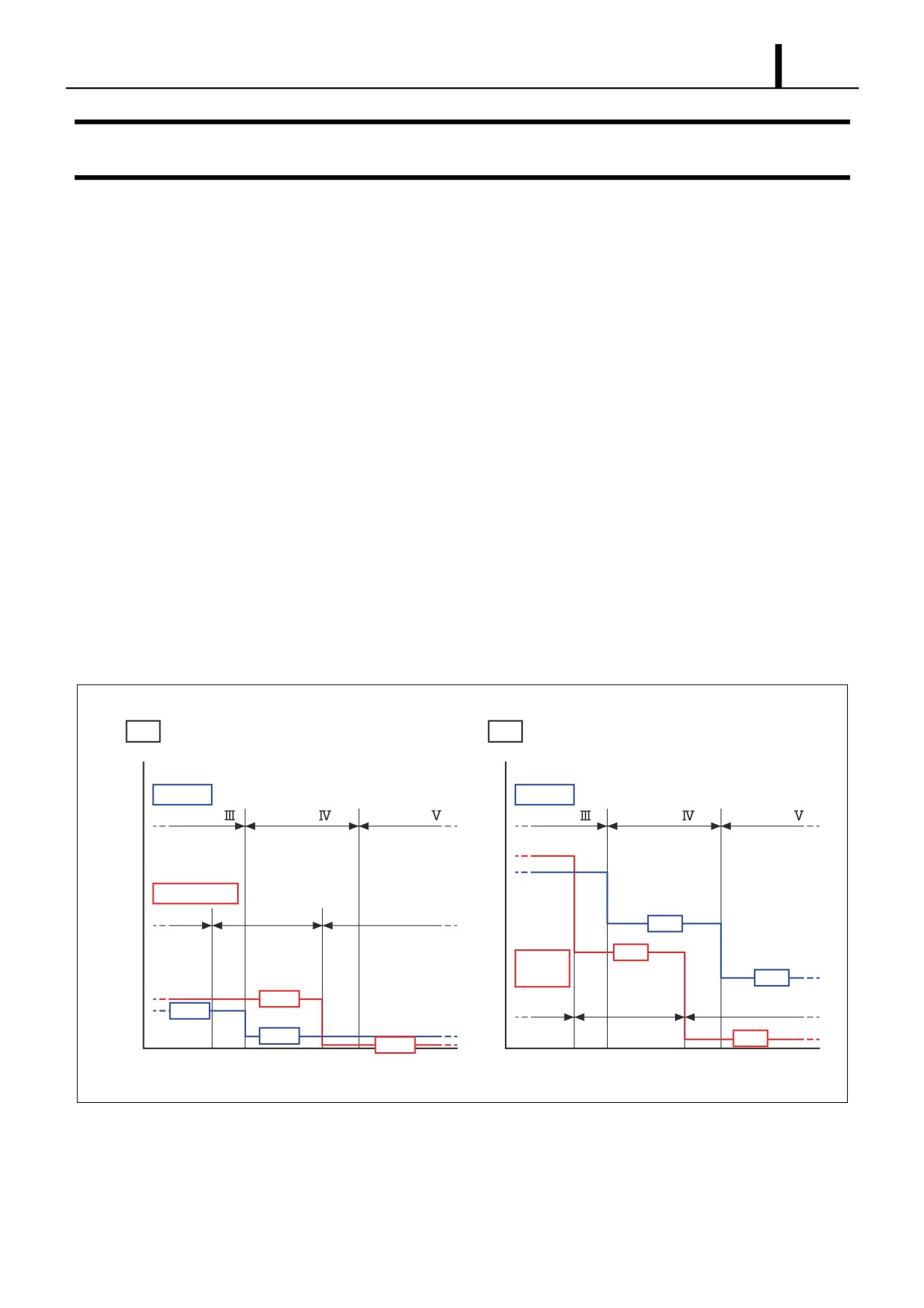
(2) Transition of Exhaust Gas Regulations (Example of Large Vehicle Diesel Regulations)
• The EURO IV regulations take effect in Europe from 2005, and the 2004 MY regulations take effect in North America
from 2004. Furthermore, the EURO V regulations will take effect in Europe from 2008, and the 2007 MY regulations
will take effect in North America from 2007. Through these measures, PM and NOx emissions are being reduced in
stages.
PM
NOx
g/kWh
g/kWh
Europe
Europe
EURO
EURO
EURO
EURO
EURO
EURO
North America
1998 MY
2004 MY
2007 MY
3.5
2.7
North
America
2.0
0.13
1998 MY
2004 MY
2007 MY
0.11
0.03
0.27
0.013
20042005
2007 2008
20042005
2007 2008
Q000989E
Operation Section
1-2
1.2 Demands On Fuel Injection System
z In order to address the various demands that are imposed on diesel vehicles, the fuel injection system (including the
injection pump and nozzles) plays a significant role because it directly affects the performance of the engine and the
vehicle. Some of the demands are: higher injection pressure, optimized injection rate, higher precision of injection timing
control, and higher precision of injection quantity control.
< NOTE >
z For further information on higher injection pressure, optimized injection rate, higher precision of injection timing control,
and higher precision of injection quantity control, see the material at the end of this document.
Operation Section
1-3
1.3 Types Of And Transitions In ECD (ELECTRONICALLY CONTROLLED
DIESEL) Systems
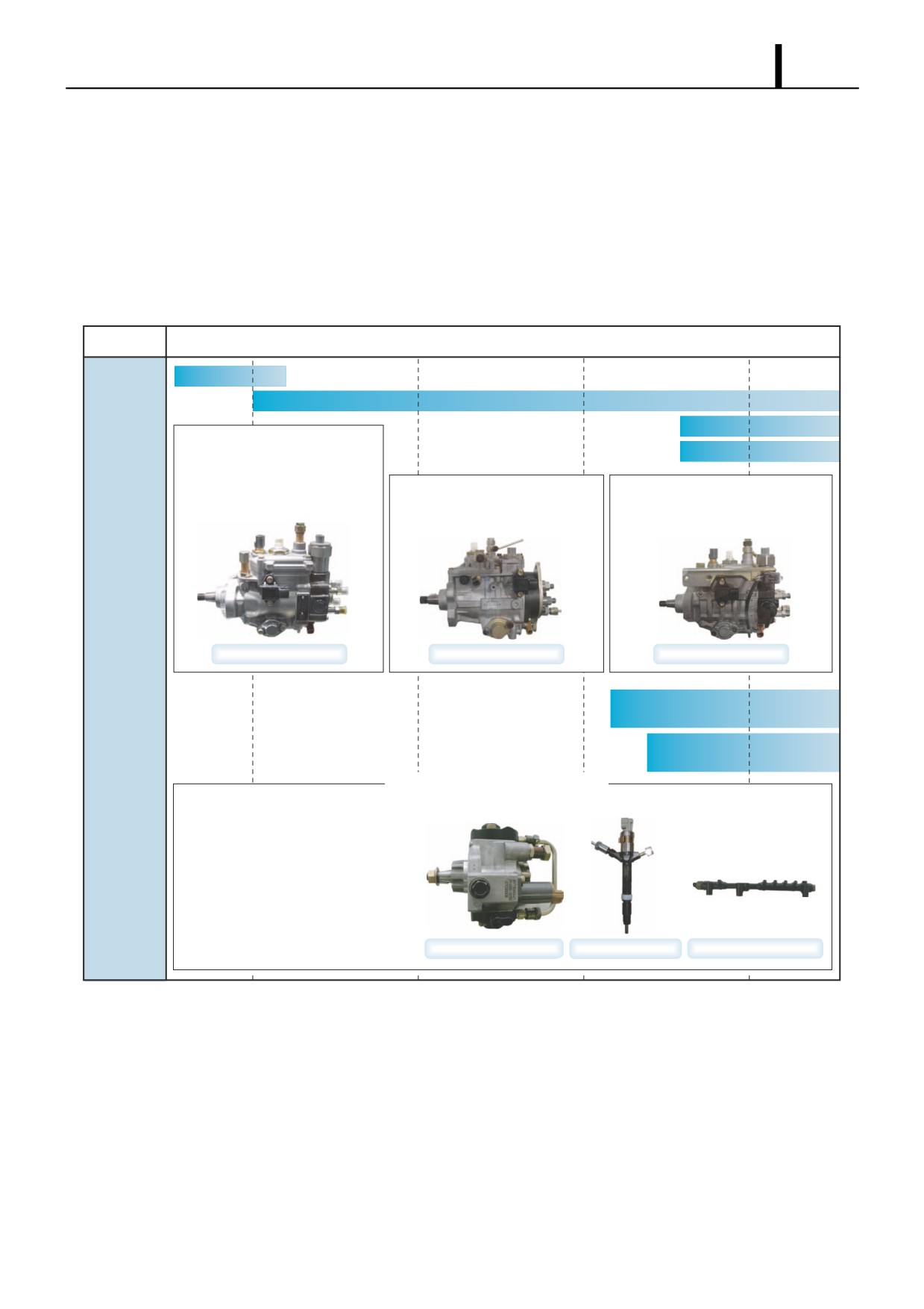
z ECD systems include the ECD-V series (V3, V4, and V5) which implements electronic control through distributed pumps
(VE type pumps), and common rail systems made up of a supply pump, rail, and injectors. Types are the ECD-V3 and
V5 for passenger cars and RVs, the ECD-V4 that can also support small trucks, common rail systems for trucks, and
common rail systems for passenger cars and RVs. In addition, there are 2nd-generation common rail systems that sup-
port both large vehicle and passenger car applications. The chart below shows the characteristics of these systems.
'85
'90
'95
'00
ECD-V1
ECD-V3
ECD-V4
· The world's first SPV (electromagnetic
spill valve system) is used for fuel
ECD-V5
injection quantity control, so the
quantity injected by each cylinder can
· Inner Cam Pumping Mechanism
· Uses pilot injection to reduce the
be controlled.
· Maximum Injection Pressure 130 MPa
engine combustion noise.
· Maximum Injection Pressure 60 MPa
· Maximum Injection Pressure
100 MPa
System
Types and
Transitions
ECD-V3
ECD-V4
ECD-V5
Large Vehicle Common Rail
(HP0)
Passenger Car Common Rail
(HP2)
Common Rail System
· Fuel raised to high pressure by the
supply pump is temporarily
accumulated in the rail, then injected
after the injector is energized.
· Uses pilot injection to reduce the
engine combustion noise
· Maximum Injection Pressure 180 MPa
Supply Pump
Injector
Rail
Q000750E
Operation Section
1-4
1.4 Common Rail System Characteristics
z The common rail system uses a type of accumulation chamber called a rail to store pressurized fuel, and injectors that
contain electronically controlled solenoid valves to inject the pressurized fuel into the cylinders.
z Because the engine ECU controls the injection system (including the injection pressure, injection rate, and injection tim-
ing), the injection system is independent and thus unaffected by the engine speed or load.
z Because the engine ECU can control injection quantity and timing to a high level of precision, even multi-injection (mul-
tiple fuel injections in one injection stroke) is possible.
z This ensures a stable injection pressure at all times, even in the low engine speed range, and dramatically decreases
the amount of black smoke ordinarily emitted by a diesel engine during start-up and acceleration. As a result, exhaust
gas emissions are cleaner and reduced, and higher power output is achieved.
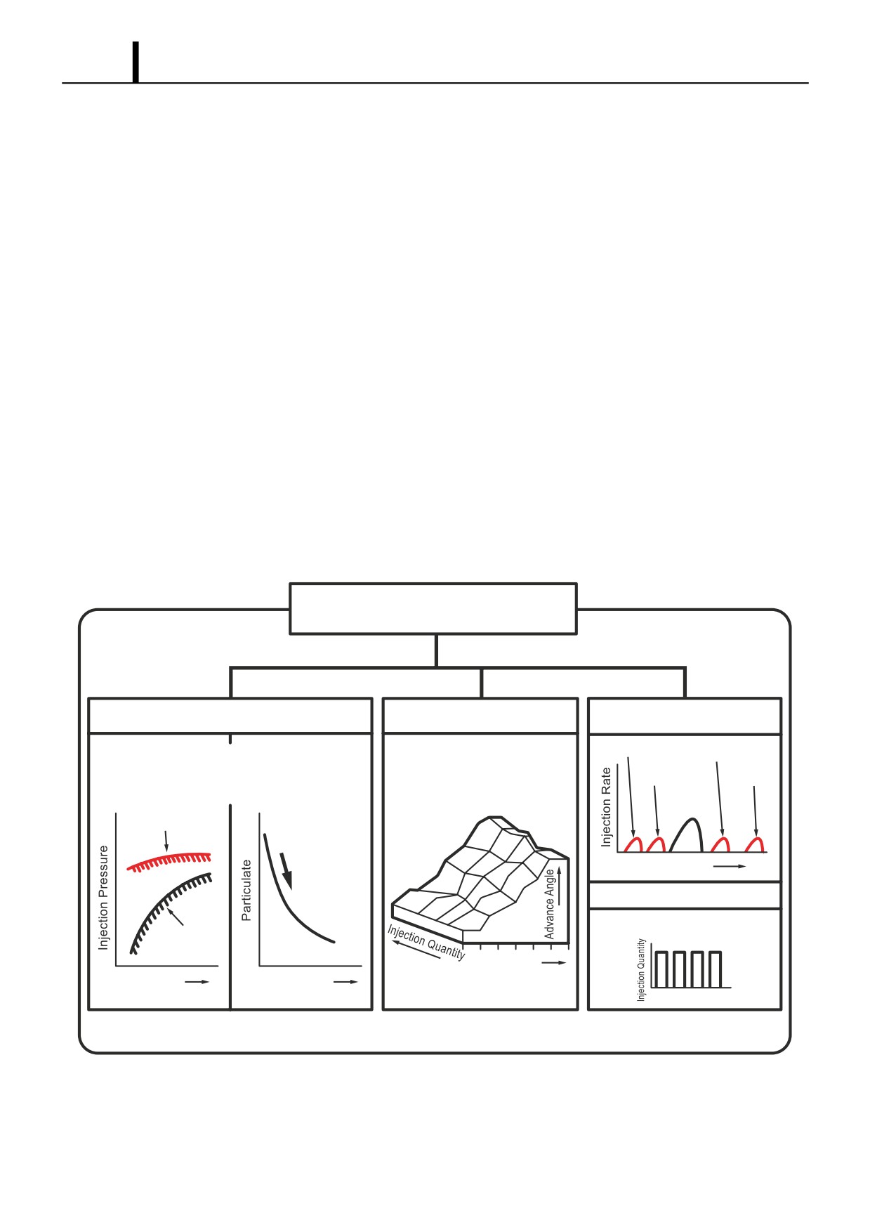
(1) Features of Injection Control
Injection Pressure Control
• Enables high-pressure injection even at low engine speeds.
• Optimizes control to minimize particulate matter and NOx emissions.
Injection Timing Control
• Enables finely tuned optimized control in accordance with driving conditions.
Injection Rate Control
• Pilot injection control injects a small amount of fuel before the main injection.
Common Rail System
Injection Pressure Control
Injection Timing Control
Injection Rate Control
Pilot injection
After-Injection
Optimized and Higher Pressure
· Injection pressure is more than double the current
Pre-Injection
Post-Injection
pressure, which makes it possible to greatly reduce
particulate matter.
Electronic Control Type
Main Injection
Common Rail System
Crankshaft Angle
Injection Quantity Control
Cylinder Injection Quantity Correction
Conventional
Pump
Speed
Speed
Injection Pressure
1
3
2
4
Q000751E
Operation Section
1-5
1.5 Common Rail System And Supply Pump Transitions
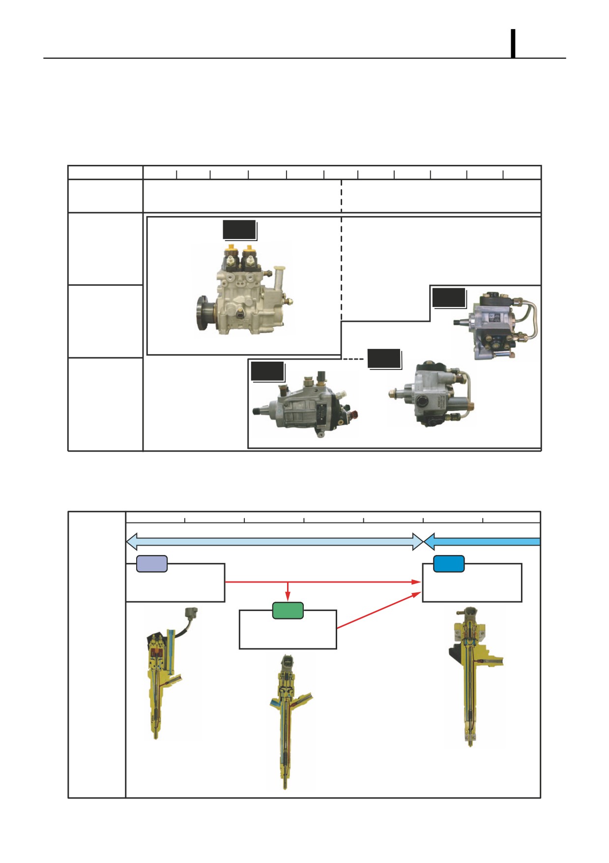
z The world's first common rail system for trucks was introduced in 1995. In 1999, the common rail system for passenger
cars (the HP2 supply pump) was introduced, and then in 2001 a common rail system using the HP3 pump (a lighter and
more compact supply pump) was introduced. In 2004, the three-cylinder HP4 based on the HP3 was introduced.
1996
1998
2000
2002
2004
2006
Common Rail
1st Generation Common Rail System
2nd Generation Common Rail System
System
HP0
120MPa
Large Trucks
HP4
Medium-Size Trucks
180MPa
Pre-Stroke Quantity Adjustment
Suction Quantity
Adjustment
HP3
HP2
Compact Trucks
180MPa
Passenger Vehicles
Suction Quantity
Adjustment
Suction Quantity
135MPa
Adjustment
Q000752E
1.6 Injector Transitions
97
98
99
00
01
02
03
1st Generation
2nd Generation
X1
G2
· 120MPa
· 180MPa
· Pilot Injection
· Multi-Injection
X2
· 135MPa
· Pilot Injection
Q000753E
Operation Section
1-6
1.7 Common Rail System Configuration
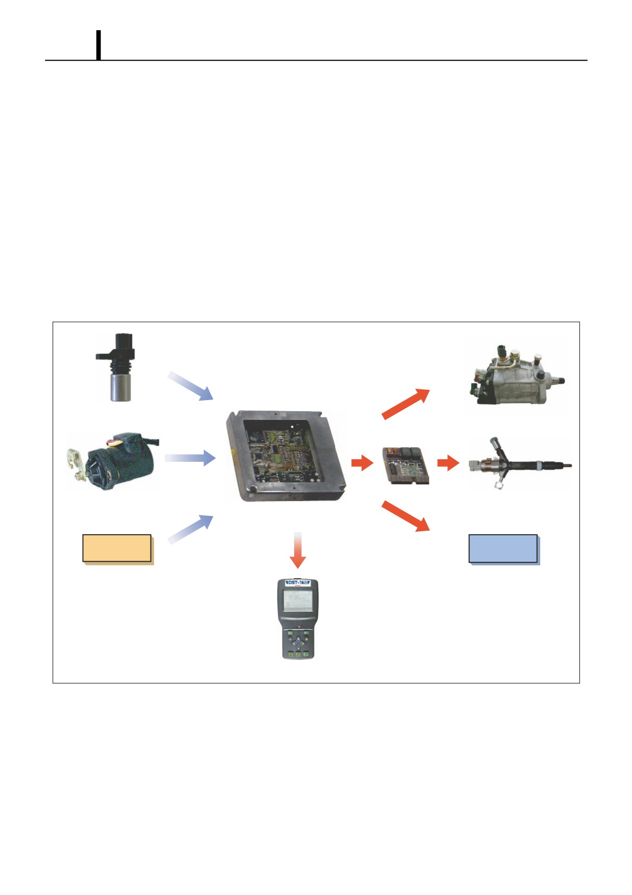
z The common rail control system can be broadly divided into the following four areas: sensors, engine ECU, EDU, and
actuators.
Sensors
z Detect the condition of the engine and the pump.
Engine ECU
z Receives signals from the sensors, calculates the proper injection quantity and injection timing for optimal engine oper-
ation, and sends the appropriate signals to the actuators.
EDU
z Enables the injectors to be actuated at high speeds. There are also types with charge circuits within the ECU that serve
the same role as the EDU. In this case, there is no EDU.
Actuators
z Operate to provide optimal injection quantity and injection timing in accordance with the signals received from the en-
gine ECU.
Engine Speed Sensor /
Supply Pump
TDC (G) Sensor
(SCV: Suction Control Valve)
EDU
Accelerator Position Sensor
Injector
Engine ECU
Other Sensors
Other Actuators
and Switches
Diagnosis
Q000754E
Operation Section
1-7
2. COMMON RAIL SYSTEM OUTLINE
2.1 Layout of Main Components
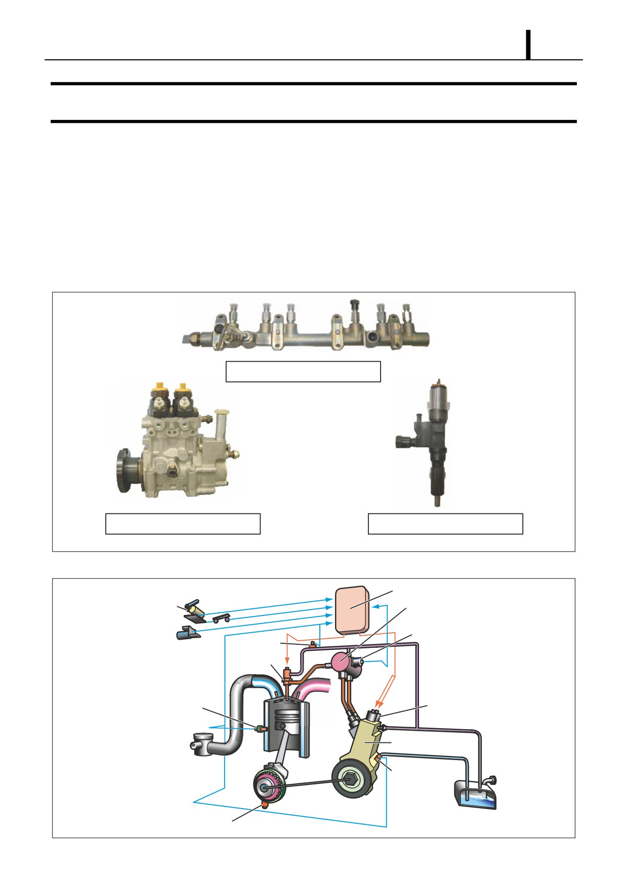
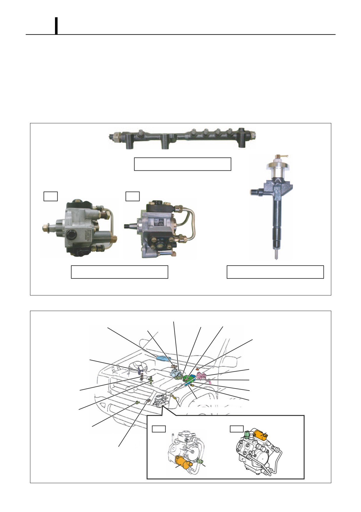
z Common rail systems are mainly made up of the supply pump, rail, and injectors. There are the following types accord-
ing to the supply pump used.
(1) HP0 Type
• This system is the first common rail system that DENSO commercialized. It uses an HP0 type supply pump and is
mounted in large trucks and large buses.
Exterior View of Main System Components
Rail
Supply Pump (HP0 Type)
Injector
Q000755E
Configuration of Main System Components (Example of HP0)
Engine ECU
Accelerator
Position Sensor
Rail
Rail Pressure Sensor
Fuel Temperature
Sensor
Injector
Coolant Temperature
PCV (Pump Control Valve)
Sensor
Supply Pump
Cylinder
Recognition Sensor
(TDC (G) Sensor)
Crankshaft Position Sensor (Engine Speed Sensor)
Q000756E
Operation Section
1-8
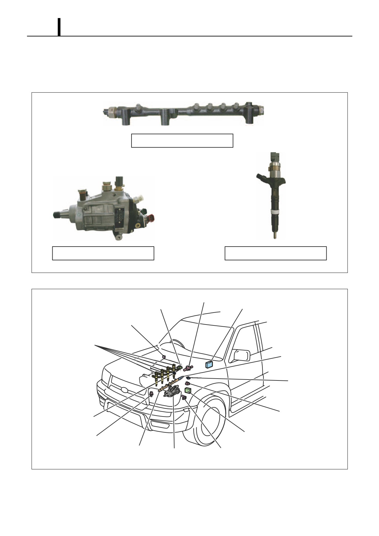
(2) HP2 Type
• This system uses a type of HP2 supply pump that has been made lighter and more compact, and is the common rail
system for passenger cars and RVs instead of the ECD-V3.
Exterior View of Main System Components
Rail
Supply Pump (HP2 Type)
Injector
Q000757E
Mounting Diagram of Main System Components
EGR Valve
Intake Air Pressure Sensor
Engine ECU
Accelerator Position Sensor
Injector
Rail Pressure Sensor
E-VRV
Coolant Temperature
Intake Air Temperature
Sensor
Sensor
EDU (Electronic Driving Unit)
Crankshaft Position Sensor
(Engine Speed Sensor)
Rail
Supply Pump
Cylinder Recognition Sensor
(TDC (G) Sensor)
Q000758E
Operation Section
1-9
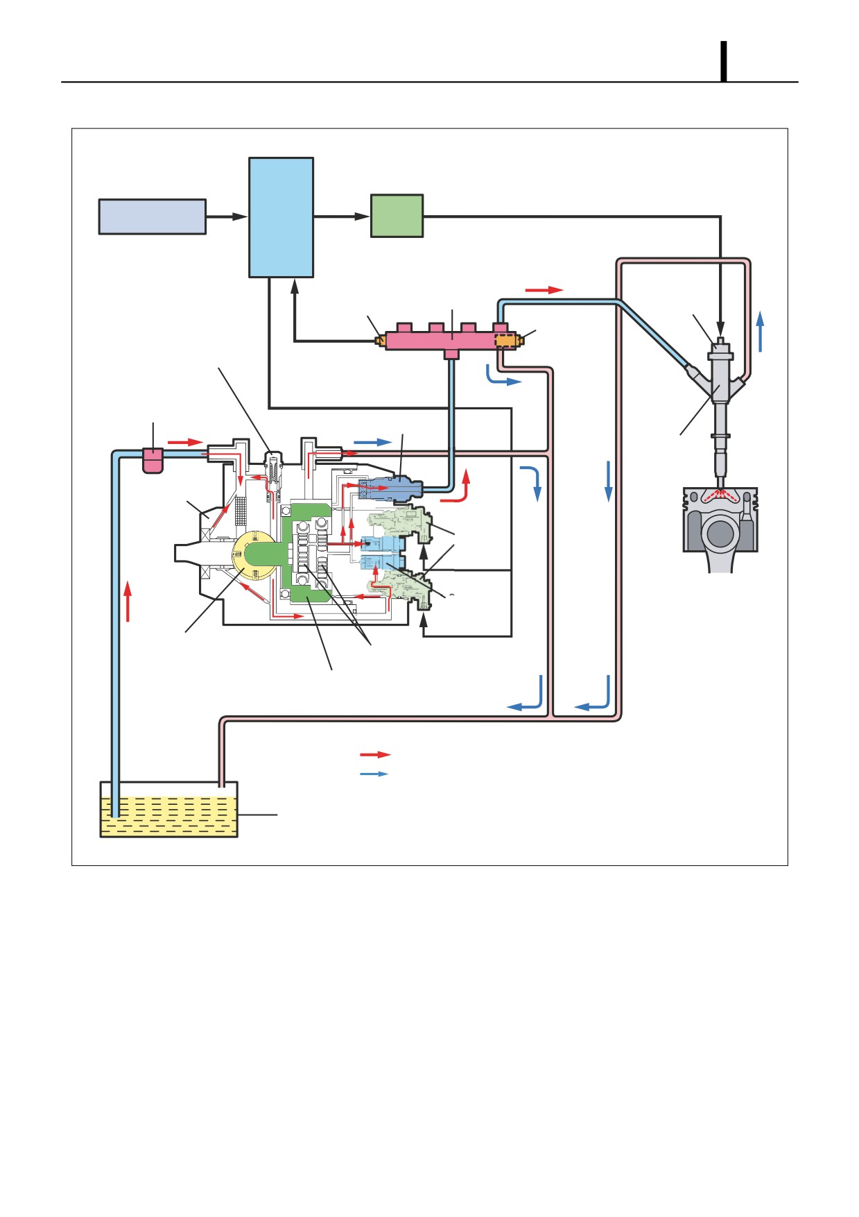
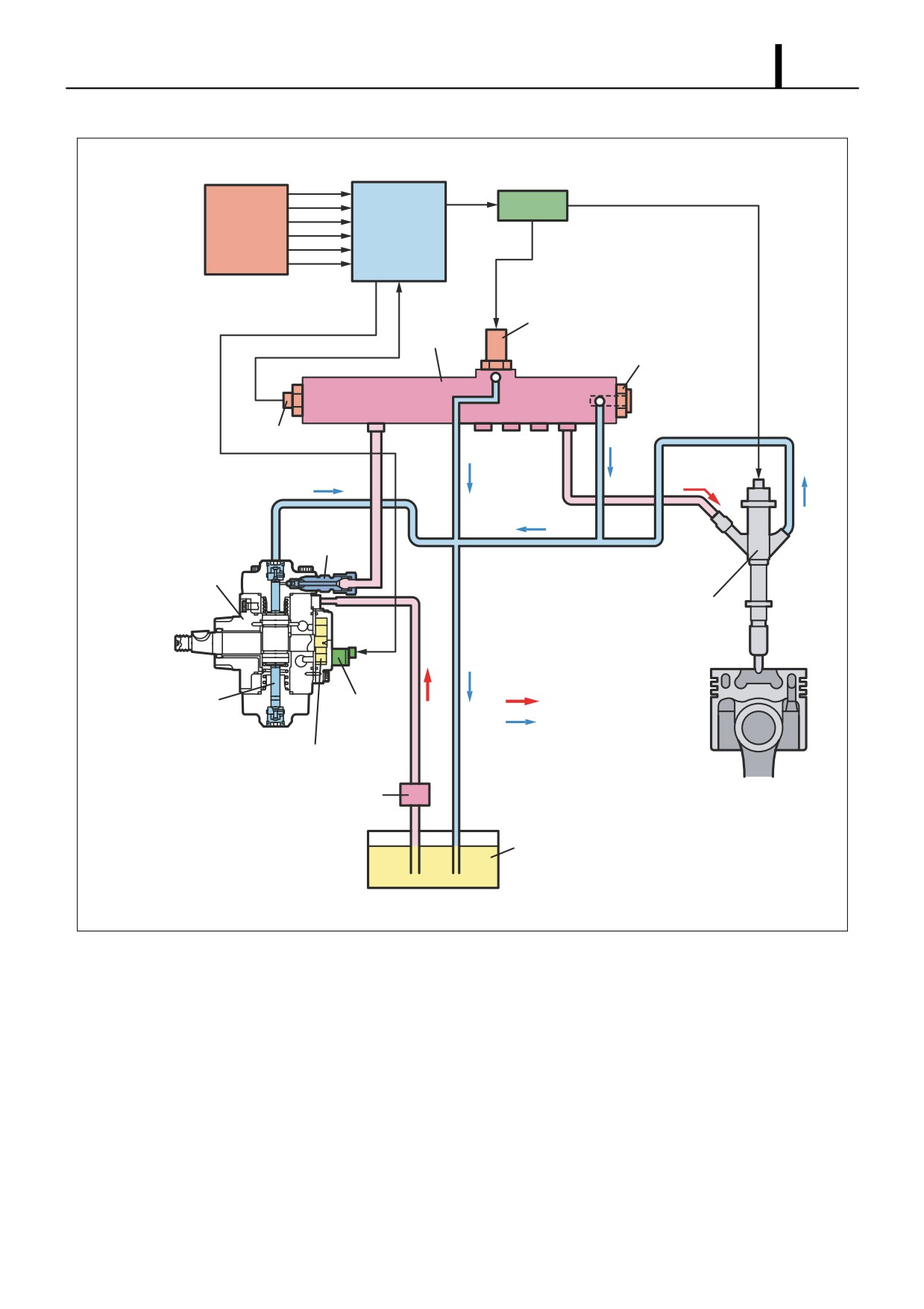
Overall System Flow (Fuel)
Engine
Various Sensors
EDU
ECU
Rail
Rail Pressure Sensor
TWV
Pressure
Limiter
Regulating Valve
Fuel Filter
Delivery Valve
Injector
Supply Pump
SCV
(Suction
Control
Valve)
Check Valve
Feed Pump
Plunger
Inner Cam
: Flow of Injection Fuel
: Flow of Leak Fuel
Fuel Tank
Q000926E
Operation Section
1-10
(3) HP3 Type, HP4 Type
HP3 Type
• This system uses an HP3 type supply pump that is compact, lightweight and provides higher pressure. It is mostly
mounted in passenger cars and small trucks.
HP4 Type
• This system is basically the same as the HP3 type, however it uses the HP4 type supply pump, which has an in-
creased pumping quantity to handle larger engines. This system is mostly mounted in medium-size trucks.
Exterior View of Main System Components
Rail
HP3
HP4
Supply Pump
Injector
Q000759E
Mounting Diagram for Main System Components
Throttle Body
Intake Air
Engine ECU
EGR Valve E-VRV for EGR
Pressure
Sensor
DLC3 Connector
Airflow Meter
(with Intake Air
Temperature Sensor)
Accelerator Position Sensor
EDU
EGR Shut-Off VSV
R/B
Coolant Temperature Sensor
Rail Pressure Sensor
Injector
Pressure Discharge Valve
Supply Pump
Crankshaft Position Sensor
HP3
HP4
SCV
(Engine Speed Sensor)
Fuel Temperature
(Suction Control
Sensor
Valve)
Cylinder Recognition Sensor
(TDC (G) Sensor)
SCV
Fuel Temperature
(Suction Control
Sensor
Valve)
Q000760E
Operation Section
1-11
Overall System Flow (Fuel)
EDU
Various
ECU
Sensors
Pressure Discharge Valve
Rail
Pressure Limiter
Rail Pressure Sensor
Delivery
Valve
Supply Pump
(HP3 or HP4)
Injector
Plunger
: Flow of Injection Fuel
SCV
(Suction
: Flow of Leak Fuel
Control Valve)
Feed Pump
Fuel Filter
Fuel Tank
Q000927E
Operation Section
1-12
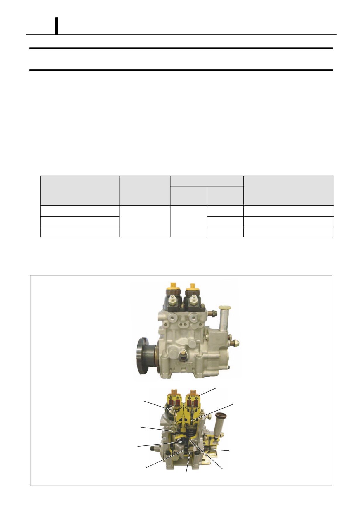
3. SUPPLY PUMP DESCRIPTION
3.1 HP0 Type
(1) Construction and Characteristics
• The HP0 supply pump is mainly made up of a pumping system as in conventional in-line pumps (two cylinders), the
PCV (Pump Control Valve) for controlling the fuel discharge quantity, the cylinder recognition sensor {TDC (G) sen-
sor}, and the feed pump.
• It supports the number of engine cylinders by changing the number of peaks on the cam. The supply pump rotates at
half the speed of the engine. The relationship between the number of engine cylinders and the supply pump pumping
is as shown in the table below.
Supply Pump
Speed Ratio
Number of Pumping Rotations for 1
Number of Engine Cylinders
Number of
(Pump: Engine)
Cam Peaks
Cycle of the Engine (2 Rotations)
Cylinders
4 Cylinders
2
4
6 Cylinders
1 : 2
2
3
6
8 Cylinders
4
8
• By increasing the number of cam peaks to handle the number of engine cylinders, a compact, two-cylinder pump unit
is achieved. Furthermore, because this pump has the same number of pumping strokes as injections, it maintains a
smooth and stable rail pressure.
PCV (Pump Control Valve)
Delivery Valve
Element
Overflow Valve
Cylinder Recognition Sensor
Feed Pump
(TDC (G) Sensor)
Pulsar for TDC (G) Sensor
Tappet
Cam x 2
Q000768E
Operation Section
1-13
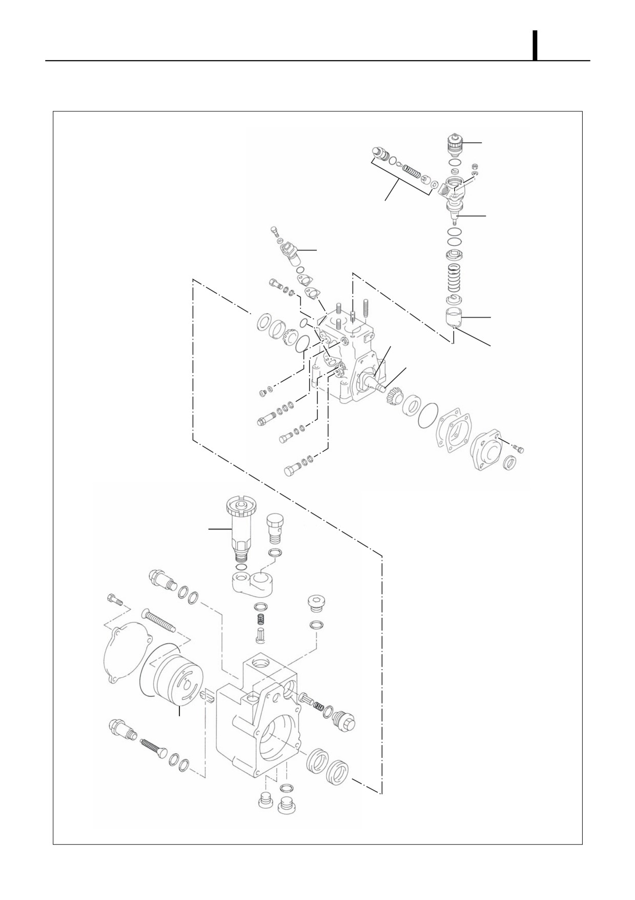
(2) Exploded View
PCV
(Pump Control Valve)
Delivery Valve
Element
Cylinder Recognition Sensor
(TDC (G) Sensor)
Tappet
Cam
Roller
Camshaft
Priming Pump
Feed Pump
Q000769E
Operation Section
1-14
(3) Supply Pump Component Part Functions
Component Parts
Functions
Feed Pump
Draws fuel from the fuel tank and feeds it to the pumping mechanism.
Overflow Valve
Regulates the pressure of the fuel in the supply pump.
PCV (Pump Control Valve)
Controls the quantity of fuel delivered to the rail.
Pumping
Cam
Actuates the tappet.
Mechanism
Tappet
Transmits reciprocating motion to the plunger.
Plunger
Moves reciprocally to draw and compress fuel.
Delivery Valve
Stops the reverse flow of fuel pumped to the rail.
Cylinder Recognition Sensor {TDC (G)
Identifies the engine cylinders.
Sensor}
Feed Pump
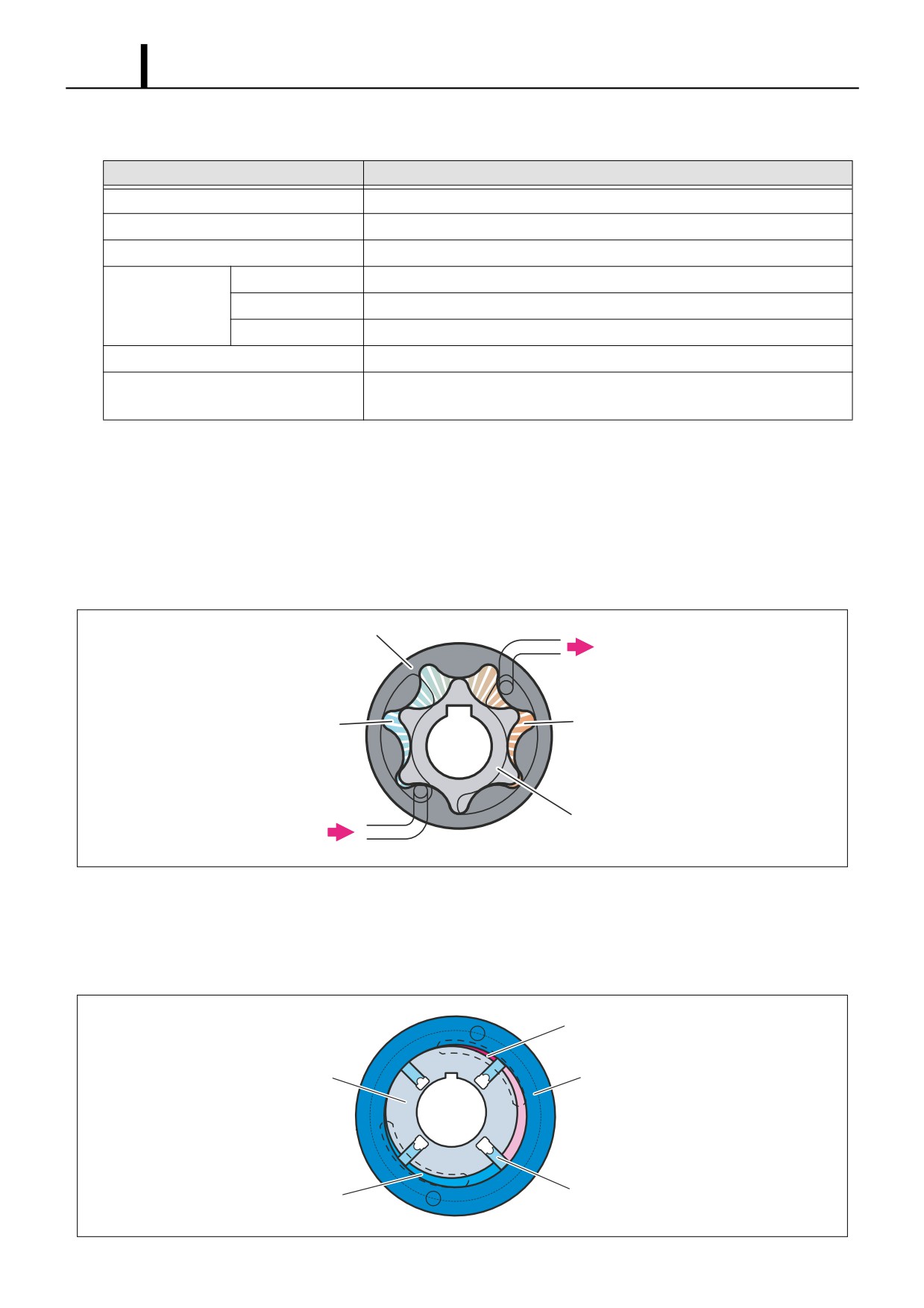
• The feed pump, which is integrated in the supply pump, draws fuel from the fuel tank and feeds it to the pump chamber
via the fuel filter. There are two types of feed pumps, the trochoid type and the vane type.
Trochoid Type
- The camshaft actuates the outer/inner rotors of the feed pump, causing them to start rotating. In accordance with
the space produced by the movement of the outer/inner rotors, the feed pump draws fuel into the suction port and
pumps fuel out the discharge port.
Outer Rotor
To Pump Chamber
Suction Port
Discharge Port
Inner Rotor
From Fuel Tank
Q000770E
Vane Type
- The camshaft actuates the feed pump rotor and the vanes slide along the inner circumference of the eccentric ring.
Along with the rotation of the rotor, the pump draws fuel from the fuel tank, and discharges it to the SCV and the
pumping mechanism.
Discharge Port
Rotor
Eccentric Ring
Vane
Suction Port
Q000771E
Operation Section
1-15
PCV: Pump Control Valve
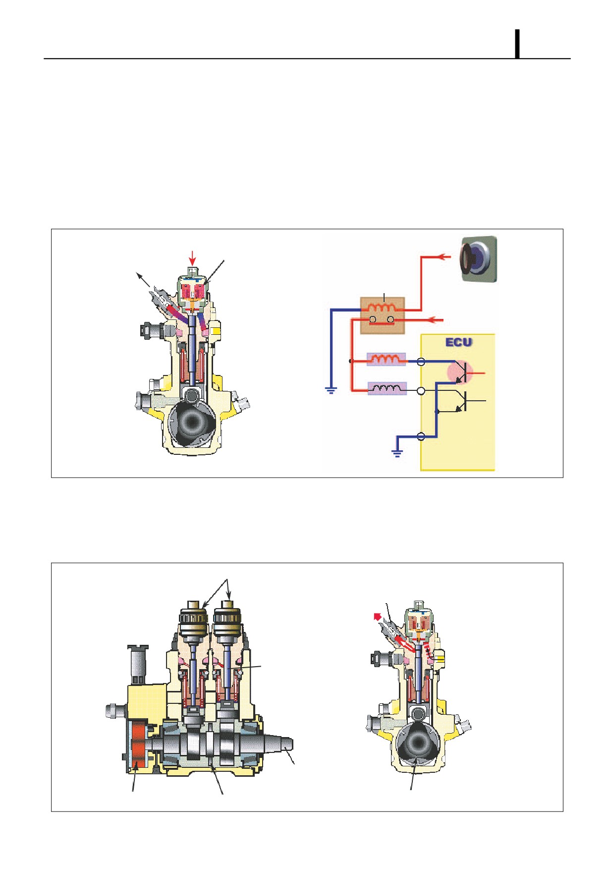
• The PCV (Pump Control Valve) regulates the fuel discharge quantity from the supply pump in order to regulate the
rail pressure. The fuel quantity discharged from the supply pump to the rail is determined by the timing with which the
current is applied to the PCV.
Actuation Circuit
- The diagram below shows the actuation circuit of the PCV. The ignition switch turns the PCV relay ON and OFF to
apply current to the PCV. The ECU handles ON/OFF control of the PCV. Based on the signals from each sensor,
it determines the target discharge quantity required to provide optimum rail pressure and controls the ON/OFF tim-
ing for the PCV to achieve this target discharge quantity.
From PCV relay
PCV
To Rail
PCV Relay
Ignition Switch
+B
PCV1
PCV2
Q000772E
Pumping Mechanism
• The camshaft is actuated by the engine and the cam actuates the plunger via the tappet to pump the fuel sent by the
feed pump. The PCV controls the discharge quantity. The fuel is pumped from the feed pump to the cylinder, and then
to the delivery valve.
PCV (Pump Control Valve)
Delivery Valve
To Rail
Plunger
Camshaft
Feed Pump
Cam (3 Lobes: 6-Cylinders)
Pulsar for TDC (G) Sensor
Q000773E
Operation Section
1-16
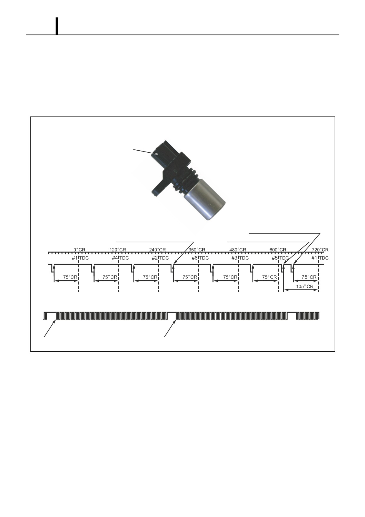
CYLINDER RECOGNITION SENSOR {TDC (G) SENSOR}
• The cylinder recognition sensor {TDC (G) sensor} uses the alternating current voltage generated by the change in the
lines of magnetic force passing through the coil to send the output voltage to the ECU. This is the same for the engine
speed sensor installed on the engine side. A disc-shaped gear, which is provided in the center of the supply pump
camshaft, has cutouts that are placed at 120? intervals, plus an extra cutout. Therefore, this gear outputs seven puls-
es for every two revolutions of the engine (for a six-cylinder engine). Through the combination of engine-side engine
speed pulses and TDC pulses, the pulse after the extra cutout pulse is recognized as the No. 1 cylinder.
· For a 6-Cylinder Engine (Reference)
Cylinder Recognition Sensor
(TDC (G) Sensor)
No.1 Cylinder TDC (G) Pulse
· TDC (G) Pulse
No.6 Cylinder TDC (G) Standard Pulse
No.1 Cylinder Recognition TDC (G) Pulse
· Engine Speed Pulse
0 2 4 6 8 101214 0 2 4 6 8101 21 4 0 2 4 6 8 101 2
0 2 4 6 8101214 0 2 4 6 8101214 0 2 4 6 8 1012
0 2 4 6 8
No.1 Cylinder Engine Speed Standard Pulse
No.6 Cylinder Engine Speed Standard Pulse
Q000774E
Operation Section
1-17
(4) Supply Pump Operation
Supply Pump Overall Fuel Flow
• The fuel is drawn by the feed pump from the fuel tank and sent to the pumping mechanism via the PCV. The PCV
adjusts the quantity of fuel pumped by the pumping mechanism to the necessary discharge quantity, and the fuel is
pumped to the rail via the delivery valve.
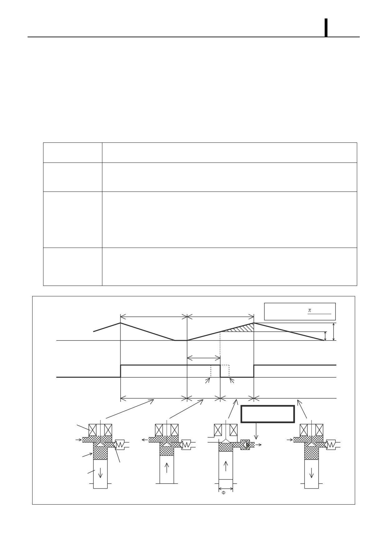
Fuel Discharge Quantity Control
• The fuel sent from the feed pump is pumped by the plunger. In order to adjust the rail pressure, the PCV controls the
discharge quantity. Actual operation is as follows.
PCV and Plunger Operation During Each Stroke
Intake Stroke (A)
In the plunger's descent stroke, the PCV opens and low-pressure fuel is suctioned into the
plunger chamber via the PCV.
Pre-Stroke (B)
Even when the plunger enters its ascent stroke, the PCV remains open while it is not energized.
During this time, fuel drawn in through the PCV is returned through the PCV without being pres-
surized (pre-stroke).
Pumping Stroke (C)
At a timing suited to the required discharge quantity, power is supplied to close the PCV, the
return passage closes, and pressure in the plunger chamber rises. Therefore, the fuel passes
through the delivery valve (reverse cut-off valve) and is pumped to the rail. Specifically, the
plunger lift portion after the PCV closes becomes the discharge quantity, and by varying the tim-
ing for the PCV closing (the end point of the plunger pre-stroke), the discharge quantity is varied
to control the rail pressure.
Intake Stroke (A)
When the cam exceeds the maximum lift, the plunger enters its descent stroke and pressure in
the plunger chamber decreases. At this time, the delivery valve closes and fuel pumping stops. In
addition, the PCV opens because it is de-energized, and low-pressure fuel is suctioned into the
plunger chamber. Specifically, the system goes into state A.
Discharge Quantity
2
d
(H-h)
Intake Stroke
Pumping Stroke
Q=
4
H
Cam Lift
h
Pre-Stroke
Open Valve
PCV Operation Close Valve
When Discharge
When Discharge
Quantity Increases
Quantity Decreases
Pump Operation
Pumping the Required
Discharge Quantity
PCV
Return
From Fuel Tank
To Rail
Pumping
Mechanism
Delivery Valve
Plunger
d
(A)
(B)
(C)
(A')
Q000775E
Operation Section
1-18
3.2 HP2 Type
(1) Construction and Characteristics
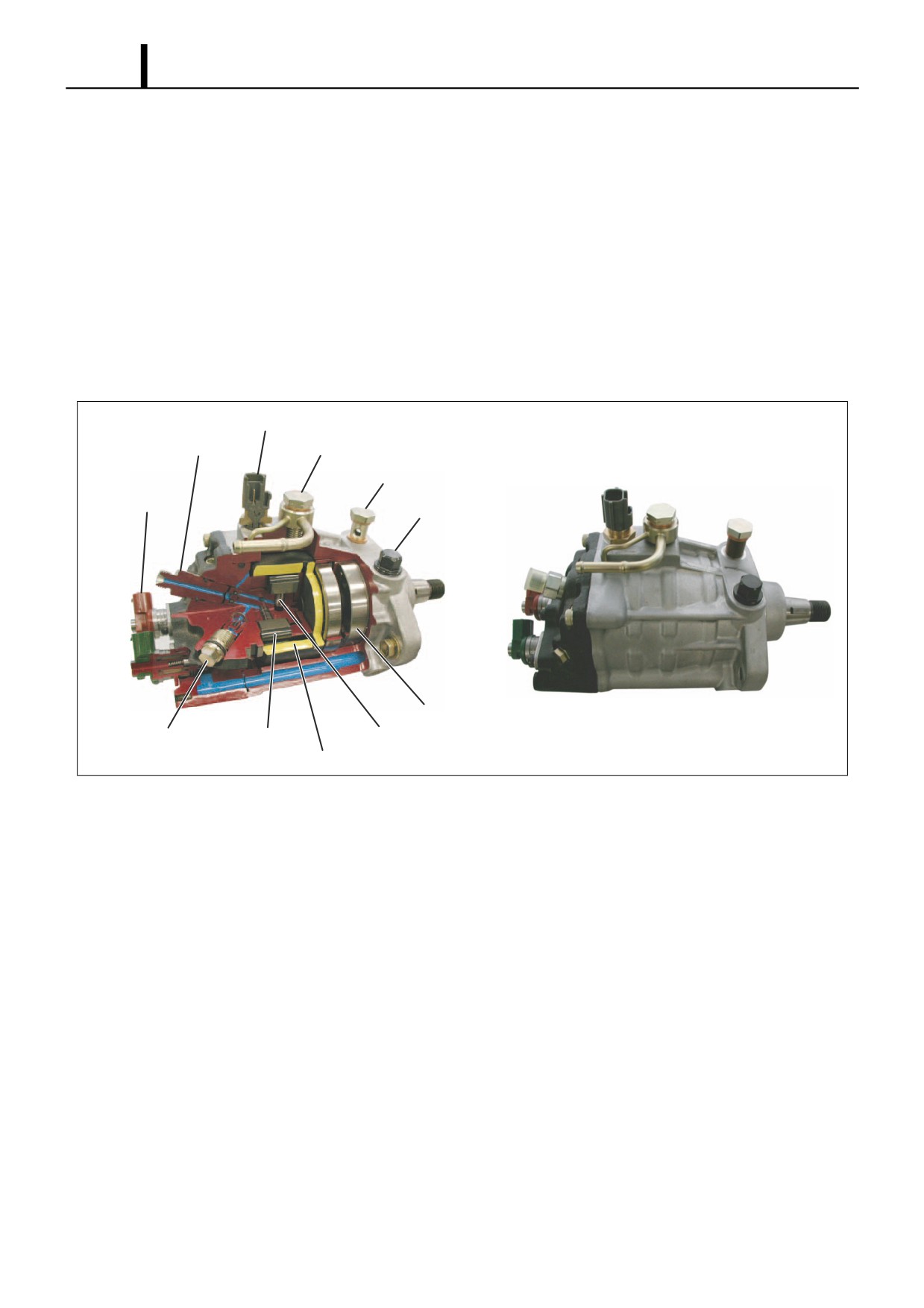
• The supply pump is primarily composed of the two pumping mechanism (inner cam, roller, two plungers) systems,
the SCV (Suction Control Valve), the fuel temperature sensor, and the feed pump (vane type), and is actuated with
half the engine rotation.
• The pumping mechanism consists of an inner cam and a plunger, and forms a tandem configuration in which two sys-
tems are arranged axially. This makes the supply pump compact and reduces the peak torque.
• The quantity of fuel discharged to the rail is controlled by the fuel suction quantity using SCV (Suction Control Valve)
control. In order to control the discharge quantity with the suction quantity, excess pumping operations are eliminated,
reducing the actuation load and suppressing the rise in fuel temperature.
Fuel Temperature Sensor
Delivery Valve
Overflow
SCV
Fuel Suction (From Fuel Tank)
(Suction Control
Valve)
Regulating Valve
Feed Pump
Check Valve
Roller
Plunger
Inner Cam
Q000818E
Operation Section
1-19
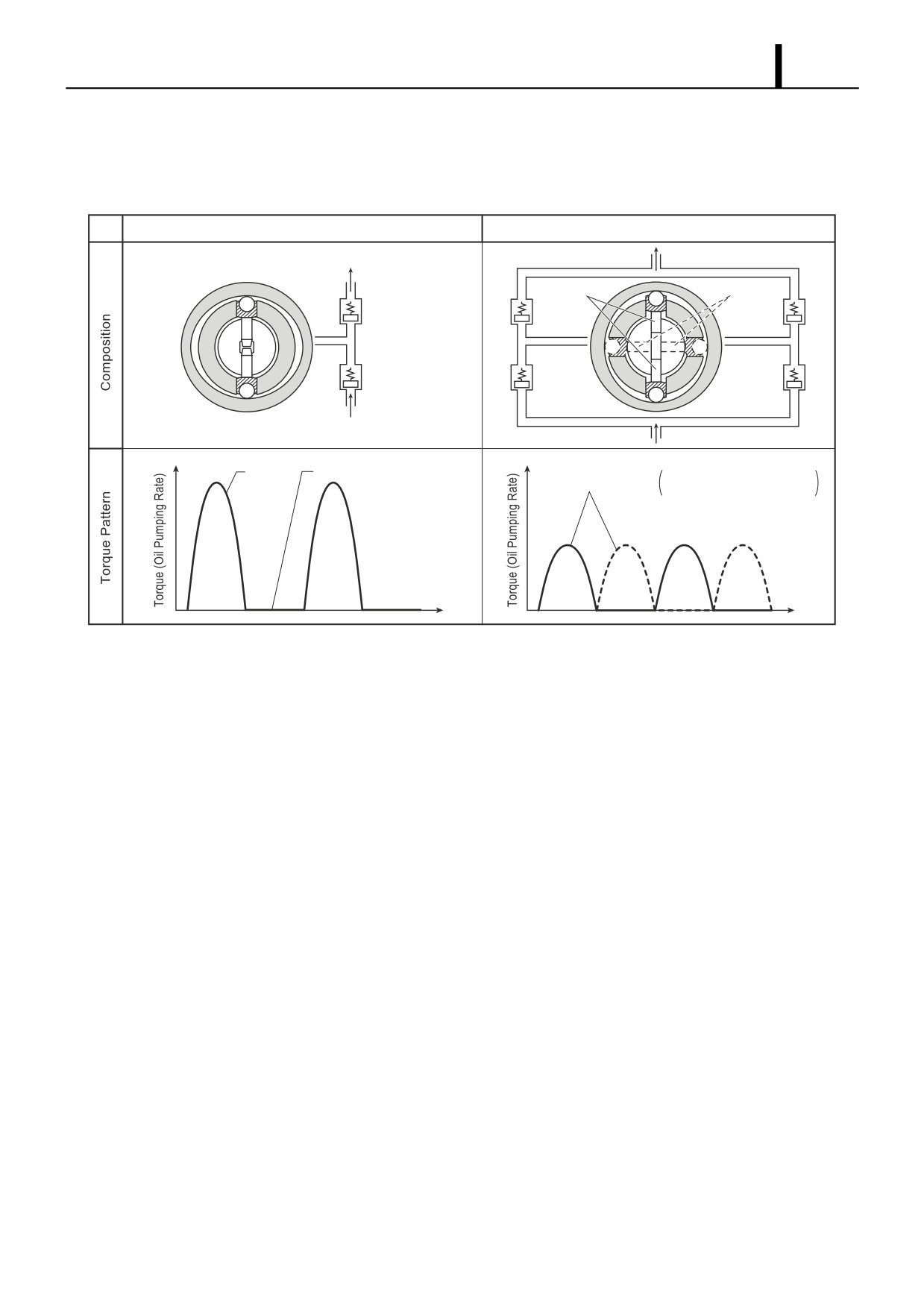
(2) Supply Pump Actuating Torque
• Because the pumping mechanism is a tandem configuration, its peak actuating torque is one-half that of a single
pump with the same discharge capacity.
Single Type
Tandem Type
Pumping
Pumping
Plunger 2
Plunger 1
Feed
Feed
Pumping
Suction
Solid Line
: Plunger 1
Pumping
Broken Line: Plunger 2
Q000819E
Operation Section
1-20
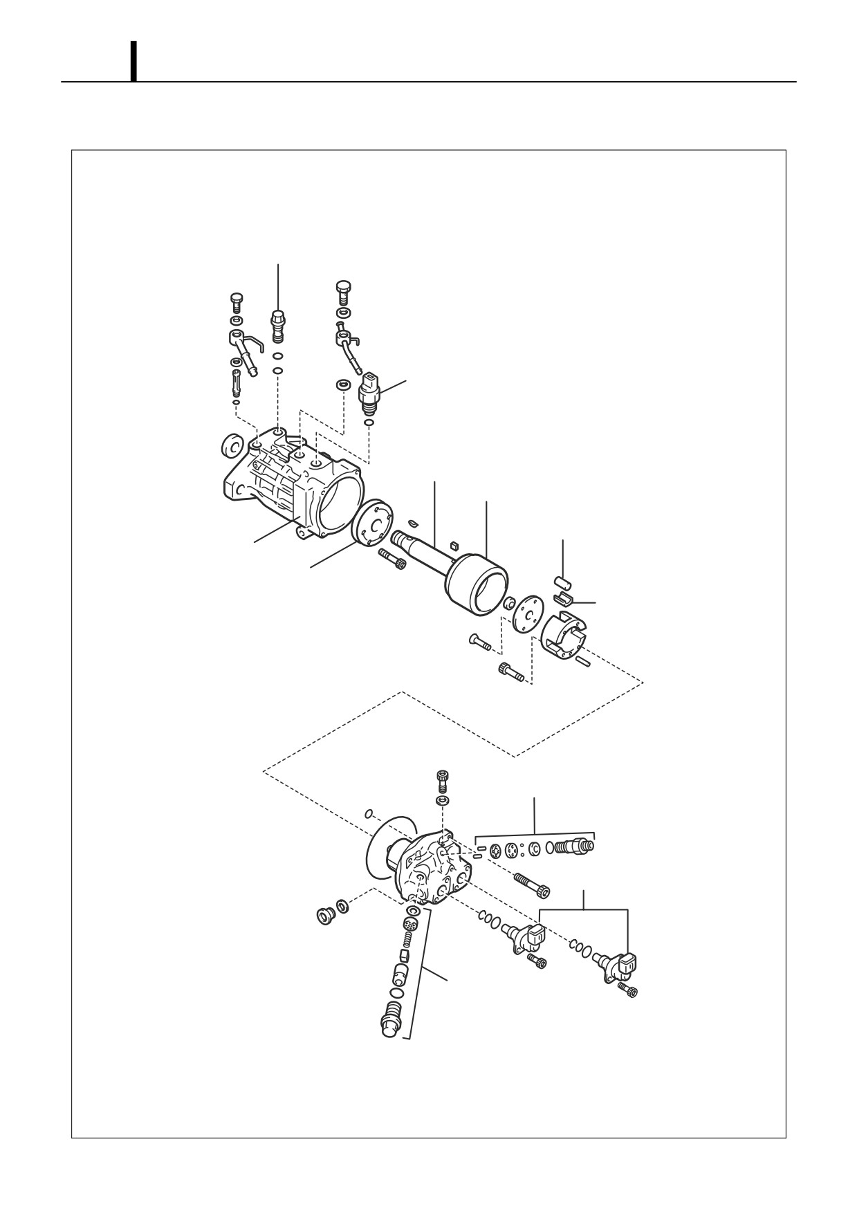
(3) Exploded View
Regulating Valve
Fuel Temperature Sensor
Camshaft
Inner Cam
Roller
Pump Body
Feed Pump
Shoe
Delivery Valve
SCV (Suction Control Valve)
Check Valve
Q000820E
Operation Section
1-21
(4) Component Part Functions
Component Parts
Functions
Feed Pump
Draws fuel from the fuel tank and feeds it to the pumping mechanism.
Regulating Valve
Regulates internal fuel pressure in the supply pump.
SCV (Suction Control Valve)
Controls the quantity of fuel that is fed to the plunger in order to control fuel
pressure in the rail.
Pumping
Inner Cam
Actuates the plunger.
Mechanism
Roller
Actuates the plunger.
Plunger
Moves reciprocally to draw and compress fuel.
Delivery Valve
Maintains high pressure by separating the pressurized area (rail) from the
pumping mechanism.
Fuel Temperature Sensor
Detects the fuel temperature.
Check Valve
Prevents the pressurized fuel in the pumping mechanism from flowing back
into the suction side.
Feed Pump
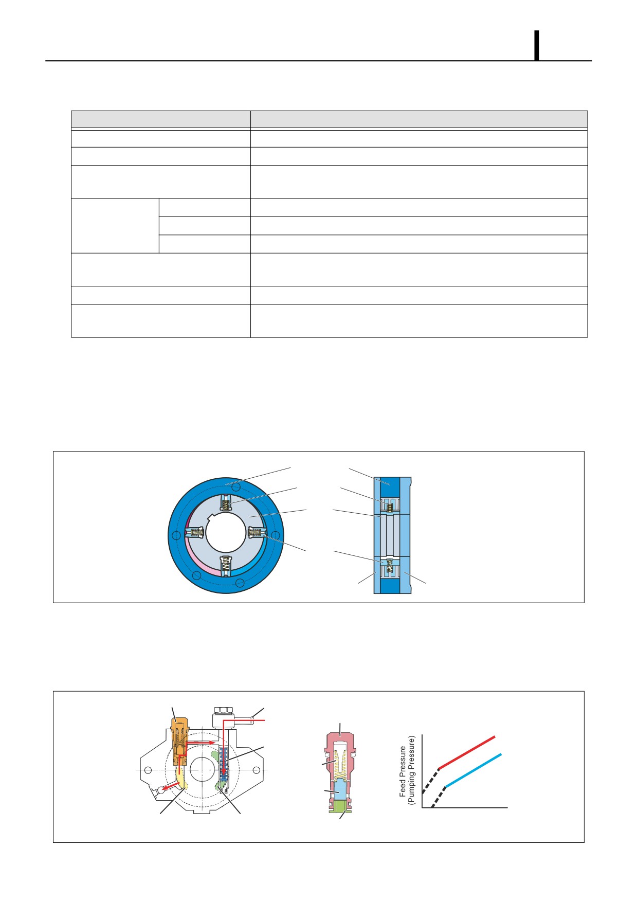
• The feed pump is a four-vaned type that draws fuel from the fuel tank and discharges it to the pumping mechanism.
The rotation of the drive shaft causes the feed pump rotor to rotate and the vane to move by sliding along the inner
surface of the casing (eccentric ring). Along with the rotation of the rotor, the pump draws fuel from the fuel tank, and
discharges it to the SCV and the pumping mechanism. To keep the vane pressed against the inner circumference, a
spring is provided inside each vane, in order to minimize fuel leakage within the pump.
Eccentric Ring
Spring
Rotor
Vane
Front Cover
Rear Cover
Q000821E
Regulating Valve
• The purpose of the regulating valve is to control the feed pressure (fuel pumping pressure) sending fuel to the pump-
ing mechanism. As the rotational movement of the pump increases and the feed pressure exceeds the pressure set
at the regulating valve, the valve opens by overcoming the spring force, allowing the fuel to return to the suction side.
Regulating Valve
Suction Inlet
Regulating Valve
Regulating Valve Body
Open Valve Pressure Characteristic
Open Valve
Filter
Pressure High
Spring
Open Valve
Piston
Pressure Low
Speed
Feed Pump
Feed Pump
Bushing
(Discharge Side)
(Suction Side)
Q000822E
Operation Section
1-22
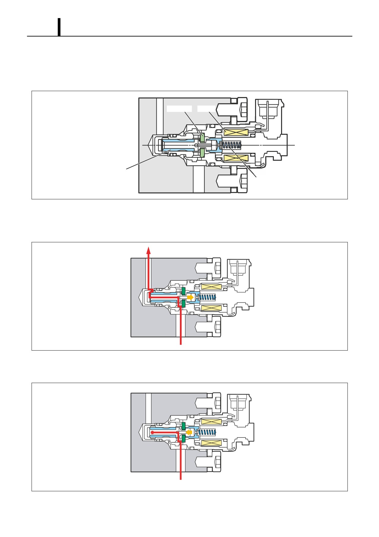
SCV: Suction Control Valve
• A solenoid type valve has been adopted. The ECU controls the duration of the current applied to the SCV in order to
control the quantity of fuel drawn into the pumping mechanism. Because only the quantity of fuel required to achieve
the target rail pressure is drawn in, the actuating load of the supply pump decreases, thus improving fuel economy.
Stopper
Coil
Needle Valve
Spring
Q000823E
SCV ON
- When current is applied to the coil, it pulls the needle valve upward, allowing fuel to be drawn into the pumping
mechanism of the supply pump.
To Pump Pumping Mechanism
From Feed Pump
Q000824E
SCV OFF
- When current is no longer applied to the coil, the needle valve closes and stops the suction of fuel.
From Feed Pump
Q000825E
Operation Section
1-23
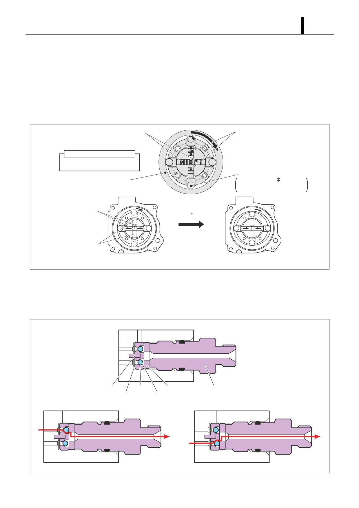
Pumping Mechanism (Plunger, Inner Cam, Roller)
• The pumping mechanism is made up of the plunger, inner cam, and roller, and it draws in the fuel discharged by the
feed pump and pumps it to the rail. Because the drive shaft and the inner cam have an integral construction, the ro-
tation of the drive shaft directly becomes the rotation of the inner cam.
• Two plunger systems are arranged in series (tandem type) inside the inner cam. Plunger 1 is situated horizontally,
and plunger 2 is situated vertically. Plunger 1 and plunger 2 have their suction and compression strokes reversed
(when one is on the intake, the other is discharging), and each plunger discharges twice for each one rotation, so for
one rotation of the supply pump, they discharge a total of four times to the rail.
Plunger 1
Plunger 2
(Horizontal)
(Vertical)
Plunger Length Combination
· Plunger 1: Medium + Medium
· Plunger 2: Short + Long
Roller
Inner Cam
Roller Diameter:
9
(Cam Lift: 3.4mm)
Roller Length: 21mm
Material: Reinforced Ceramic
Plunger 1
Cam 90 Rotation
Plunger 2
Plunger 1: Start of Suction
Plunger 1: Start of Pumping
Plunger 2: Start of Pumping
Plunger 2: Start of Suction
Q000826E
Delivery Valve
• The delivery valve, which contains two valve balls, delivers the pressurized fuel from plungers 1 and 2 to the rail in
alternating strokes. When the pressure in the plunger exceeds the pressure in the rail, the valve opens to discharge
fuel.
From Plunger 1
To Rail
From Plunger 2
Pin
Guide
Stopper
Holder
Gasket
Valve Ball
· When Plunger 1 Pumping
· When Plunger 2 Pumping
Q000827E
Operation Section
1-24
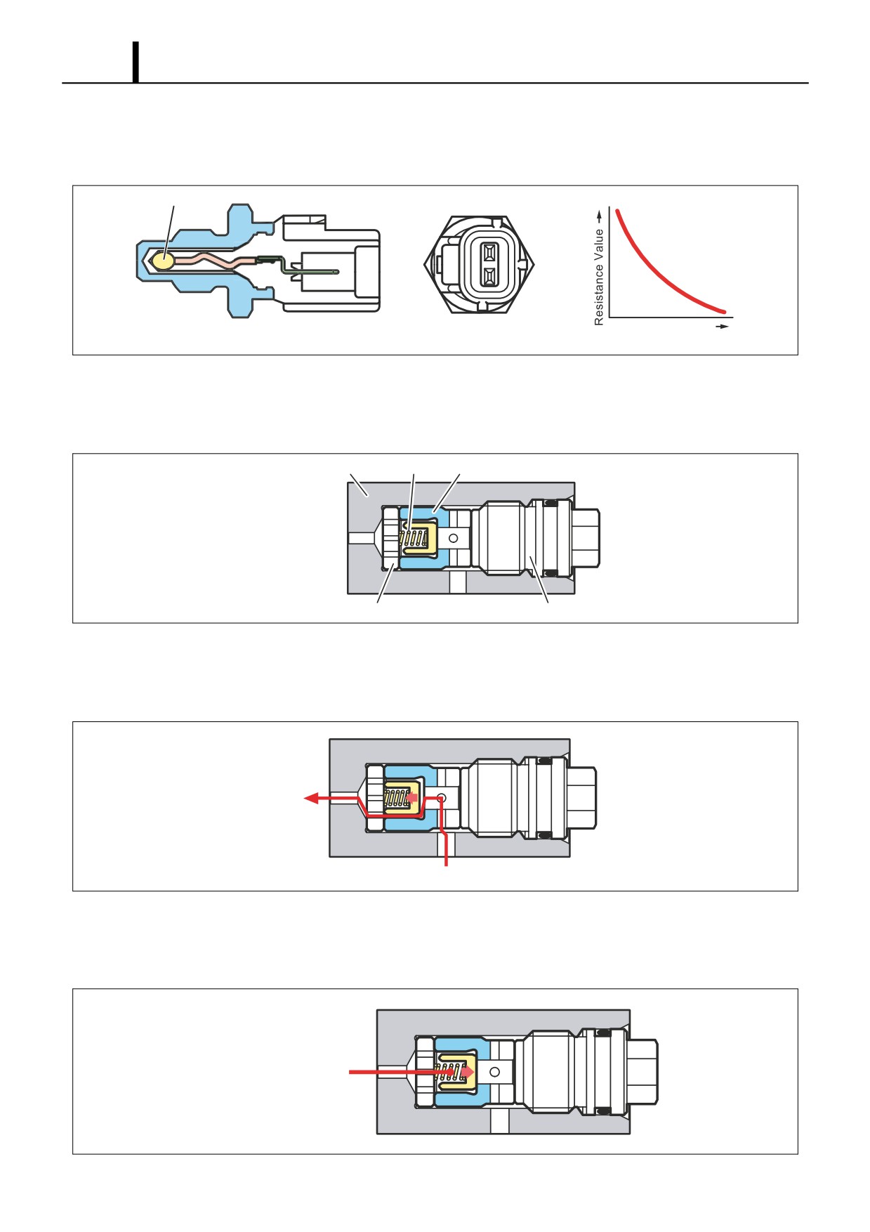
Fuel Temperature Sensor
• The fuel temperature sensor is installed on the fuel intake side and utilizes the characteristics of a thermistor in which
the electric resistance changes with the temperature in order to detect the fuel temperature.
Thermistor
Resistance - Temperature
Characteristic
Temperature
Q000828E
Check Valve
• The check valve, which is located between the SCV (Suction Control Valve) and the pumping mechanism, prevents
the pressurized fuel in the pumping mechanism from flowing back into the SCV.
Pump Housing
Spring
Valve
To Pumping Mechanism
To SCV
Stopper
Plug
Q000829E
Check Valve Open
- During fuel suction (SCV ON), the feed pressure opens the valve, allowing fuel to be drawn into the pumping mech-
anism.
To Pumping Mechanism
From SCV
Q000830E
Check Valve Closed
- During fuel pumping (SCV OFF), the pressurized fuel in the pumping mechanism closes the valve, preventing fuel
from flowing back into the SCV.
From Pumping Mechanism
Q000831E
Operation Section
1-25
(5) Supply Pump Operation
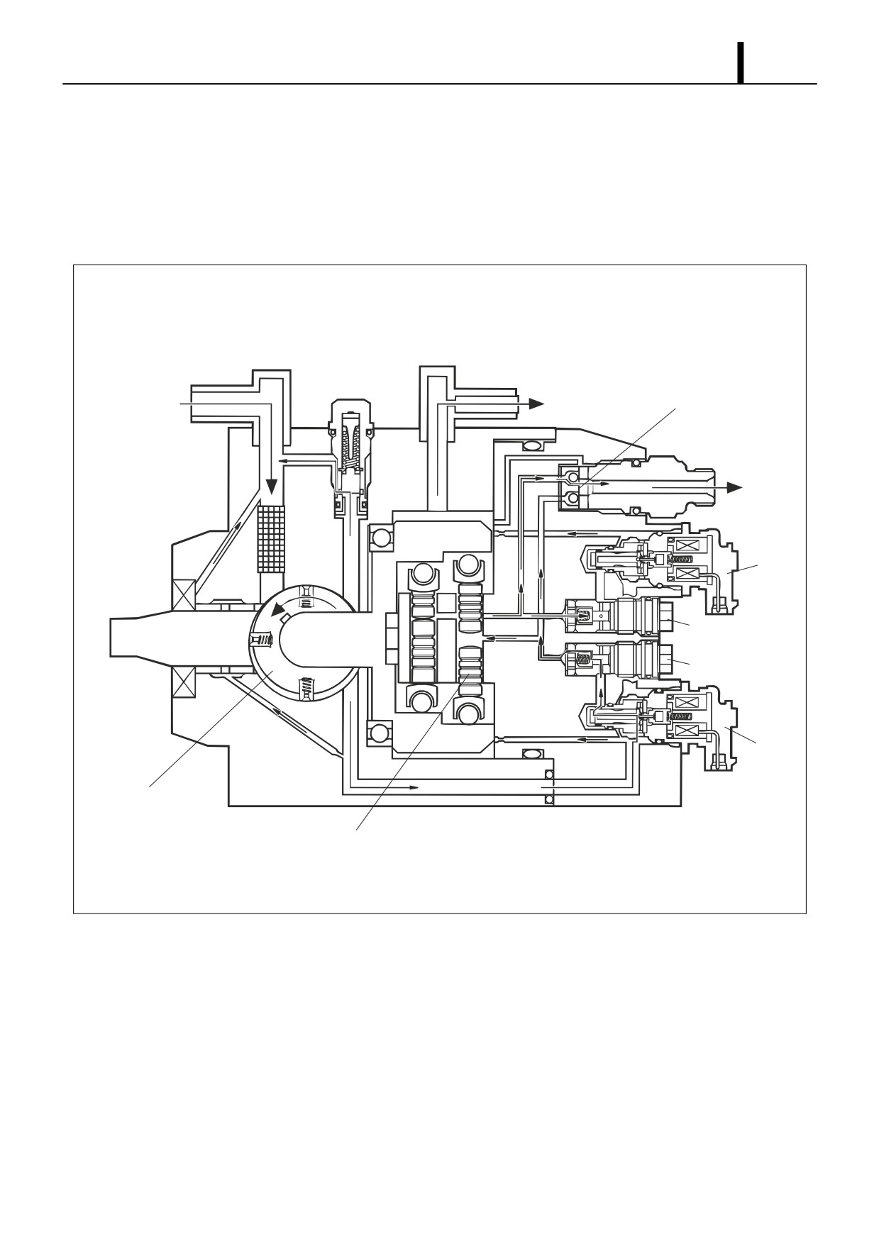
Supply Pump Overall Fuel Flow
• Fuel is suctioned by the feed pump from the fuel tank and sent to the SCV. At this time, the regulating valve adjusts
the fuel pressure to below a certain level. Fuel sent to the feed pump has the required discharge quantity adjusted by
the SCV and enters the pumping mechanism through the check valve. The fuel pumped by the pumping mechanism
is pumped through the delivery valve to the rail.
Overflow Orifice
Regulating Valve
Delivery Valve
From Fuel Tank
To Tank
To Rail
Cam
SCV1
Check Valve 1
Check Valve 2
Head
SCV2
Feed Pump
Plunger
Q000832E
Operation Section
1-26
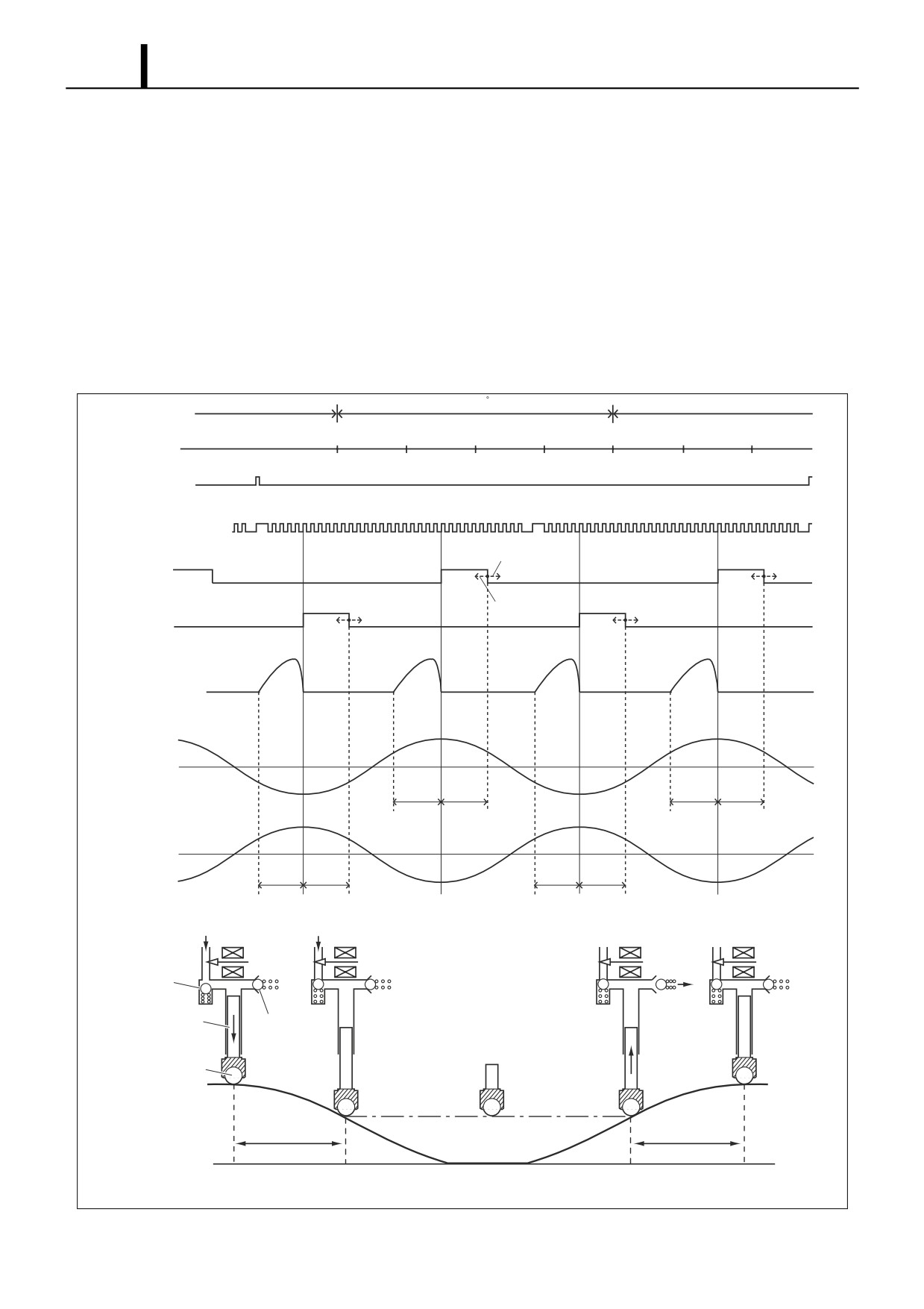
Fuel Discharge Quantity Control
• The diagram below shows that the suction starting timing (SCV (Suction Control Valve) ON) is constant (determined
by the pump speed) due to the crankshaft position sensor signal. For this reason, the fuel suction quantity is controlled
by changing the suction ending timing (SCV OFF). Hence, the suction quantity decreases when the SCV is turned
OFF early and the quantity increases when the SCV is turned OFF late.
• During the intake stroke, the plunger receives the fuel feed pressure and descends along the cam surface. When the
SCV turns OFF (suction end), the feed pressure on the plunger ends and the descent stops. Since the suction quantity
varies, when suction ends (except for maximum suction) the roller separates from the cam surface.
• When the drive shaft rotates and the cam peak rises and the roller comes in contact with the cam surface again, the
plunger is pressed by the cam and starts pumping. Since the suction quantity = the discharge quantity, the discharge
quantity is controlled by the timing with which the SCV is switched OFF (suction quantity).
Crankshaft
360 CR
Angle
TDC #1
TDC #3
TDC #4
TDC #2
Compression
Top Dead Center
Cylinder Recognition
Sensor Signal
0 2 4 6 8 10121416 0 2 4 6 8 101214
0 2 4
6 8 10121416 0 2 4 6 8 101214
Crankshaft Position
Sensor Signal
Increased Suction
Quantity
Suction
Suction
ON
SCV 1
OFF
Suction
Decreased Suction
Suction
ON
SCV 2
Quantity
OFF
Delivery Valve
Discharge
Horizontal
Cam Lift
Pumping
Suction
Pumping
Suction
Vertical
Cam Lift
Pumping
Suction
Pumping
Suction
Fuel
Fuel
SCV
ON
OFF
OFF
OFF
Check Valve
Fuel
Plunger
Delivery Valve
Roller
Suction
Pumping
Start of Suction
End of Suction
Start of Pumping End of Pumping
Q000833E
Operation Section
1-27
3.3 HP3 Type
(1) Construction and Characteristics
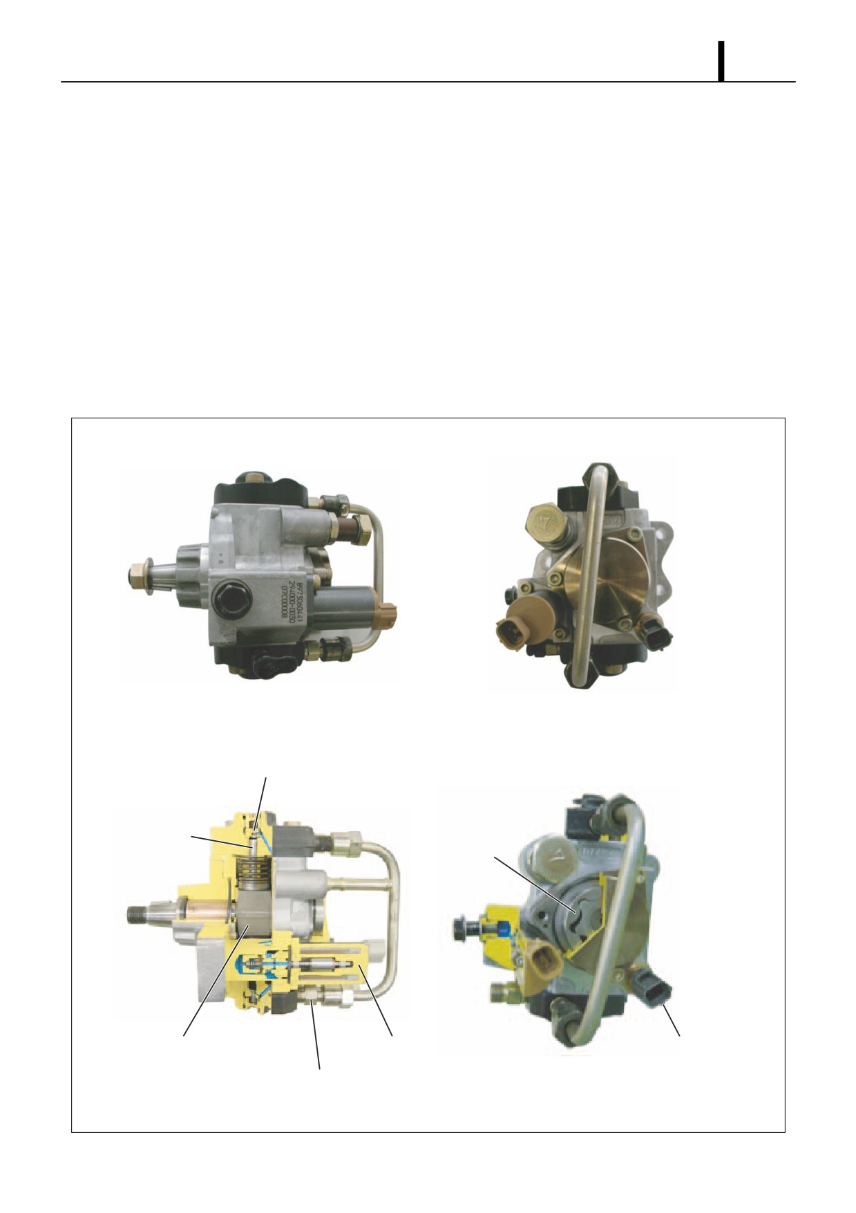
• The supply pump is primarily composed of the pump unit (eccentric cam, ring cam, two plungers), the SCV (suction
control valve), the fuel temperature sensor and the feed pump (trochoid type), and is actuated at 1/1 or 1/2 the engine
rotation.
• The two compact pump unit plungers are positioned symmetrically above and below on the outside of the ring cam.
• The fuel discharge quantity is controlled by the SCV, the same as for the HP2, in order to reduce the actuating load
and suppress the rise in fuel temperature. In addition, there are two types of HP3 SCV: the normally open type (the
suction valve opens when not energized) and the normally closed type (the suction valve is closed when not ener-
gized).
• With a DPNR system (Diesel Particulate NOx Reduction) system, there is also a flow damper. The purpose of this
flow damper is to automatically shut off the fuel if a leak occurs in the fuel addition valve passage within the DPNR.
Suction Valve
Plunger
Feed Pump
Ring Cam
SCV (Suction Control Valve)
Fuel Temperature Sensor
Delivery Valve
Q000835E
Operation Section
1-28
(2) Exploded View
Delivery Valve
Element Sub-Assembly
Delivery Valve
Fuel Temperature Sensor
Plunger
Feed Pump
Regulating Valve
SCV
(Suction Control Valve)
Ring Cam
Pump Housing
Plunger
Eccentric Cam
Camshaft
Delivery Valve
Element Sub-Assembly
Q000836E
Operation Section
1-29
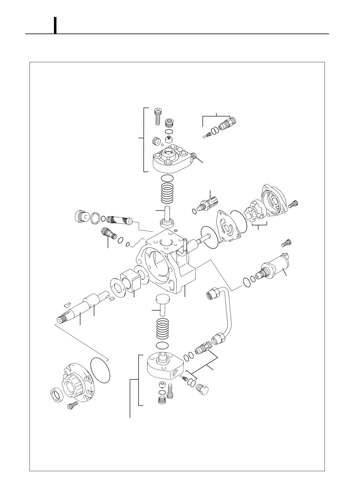
(3) Component Part Functions
Component Parts
Functions
Feed Pump
Draws fuel from the fuel tank and feeds it to the plunger.
Regulating Valve
Regulates the pressure of the fuel in the supply pump.
SCV (Suction Control Valve)
Controls the quantity of fuel that is fed to the plungers.
Pump Unit
Eccentric Cam
Actuates the ring cam.
Ring Cam
Actuates the plunger.
Plunger
Moves reciprocally to draw and compress fuel.
Delivery Valve
Prevents reverse flow from the rail of the fuel pumped from the plunger.
Fuel Temperature Sensor
Detects the fuel temperature.
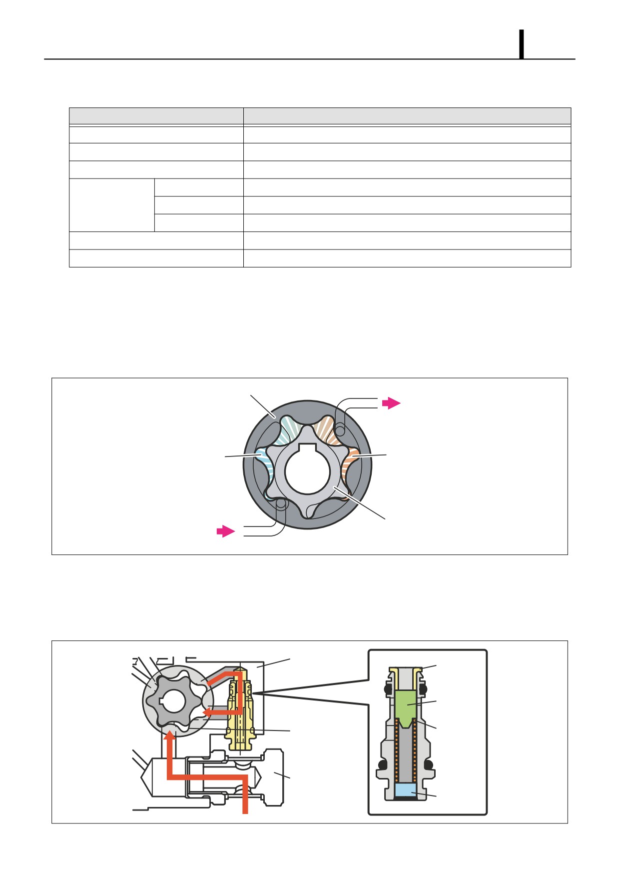
Feed Pump
• The trochoid type feed pump, which is integrated in the supply pump, draws fuel from the fuel tank and feeds it to the
two plungers via the fuel filter and the SCV (Suction Control Valve). The drive shaft actuates the outer/inner rotors of
the feed pump, thus causing the rotors to start rotating. In accordance with the space that increases and decreases
with the movement of the outer and inner rotors, the feed pump draws fuel into the suction port and pumps fuel out
the discharge port.
Outer Rotor
To Pump Chamber
Suction Port
Discharge Port
Inner Rotor
From Fuel Tank
Q000770E
Regulating Valve
• The regulating valve keeps the fuel feed pressure (discharge pressure) below a certain level. If the pump speed in-
creases and the feed pressure exceeds the preset pressure of the regulating valve, the valve opens by overcoming
the spring force in order to return the fuel to the suction side.
Pump Housing
Bushing
Piston
Feed Pump
Spring
SCV
Plug
Q000837E
Operation Section
1-30
Suction Control Valve (SCV)
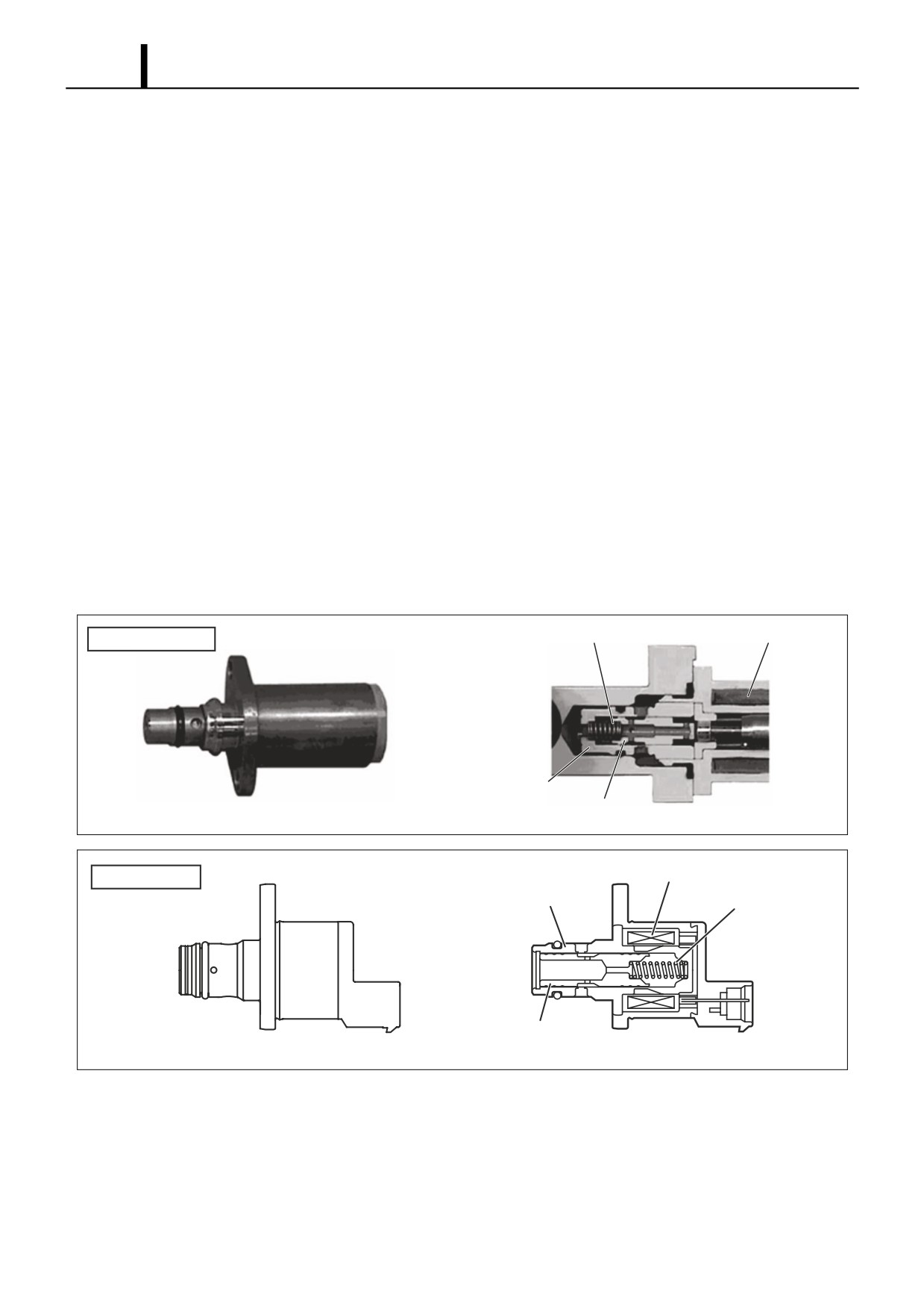
• In contrast to the HP2, the SCV for the HP3 supply pump is equipped with a linear solenoid valve. The fuel flow vol-
ume supplied to the high-pressure plunger is controlled by adjusting the engine ECU supplies power to the SCV (duty
ratio control). When current flows to the SCV, the internal armature moves according to the duty ratio. The armature
moves the needle valve, controlling the fuel flow volume according to the amount that the valve body fuel path is
blocked. Control is performed so that the supply pump suctions only the necessary fuel quantity to achieve the target
rail pressure. As a result, the supply pump actuation load is reduced.
• There are two types of HP3 SCV: the normally open type (the suction valve opens when not energized) and the nor-
mally closed type (the suction valve is closed when not energized). The operation of each type is the reverse of that
of the other.
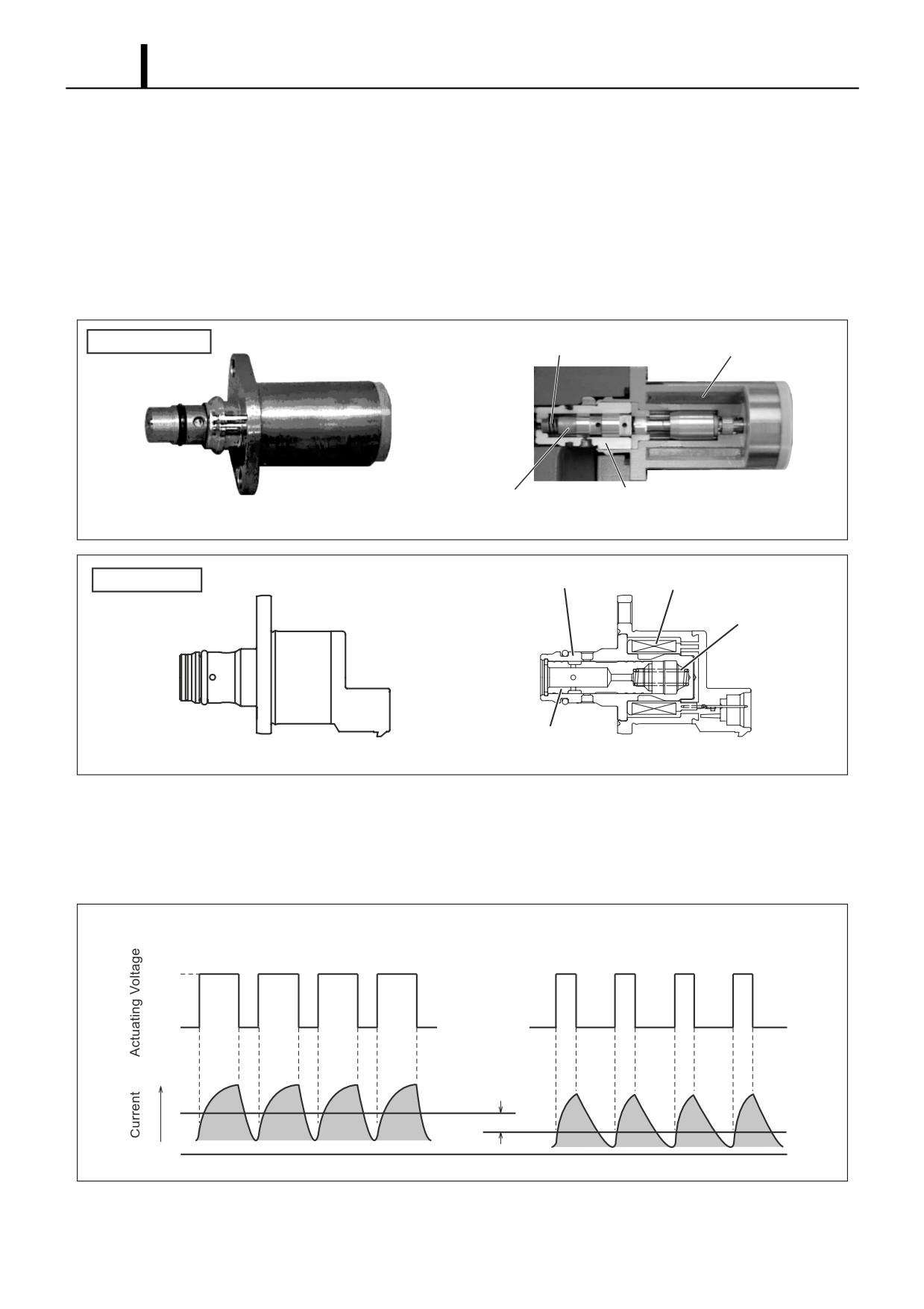
• In recent years, a compact SCV has been developed. Compared to the conventional SCV, the position of the return
spring and needle valve in the compact SCV are reversed. For this reason, operation is also reversed.
Normally Open Type
- When the solenoid is not energized, the return spring pushes against the needle valve, completely opening the fuel
passage and supplying fuel to the plungers. (Total quantity suctioned → Total quantity discharged)
- When the solenoid is energized, the armature pushes the needle valve, which compresses the return spring and
closes the fuel passage. In contrast, the needle valve in the compact SCV is pulled upon, which compresses the
return spring and closes the fuel passage.
- The solenoid ON/OFF is actuated by duty ratio control. Fuel is supplied in an amount corresponding to the open
surface area of the passage, which depends on the duty ratio, and then is discharged by the plungers.
Return Spring
Solenoid
Conventional SCV
Valve Body
Needle Valve
External View
Cross Section
Q002340E
Compact SCV
Solenoid
Valve Body
Return Spring
Needle Valve
External View
Cross Section
Q002309E
Operation Section
1-31
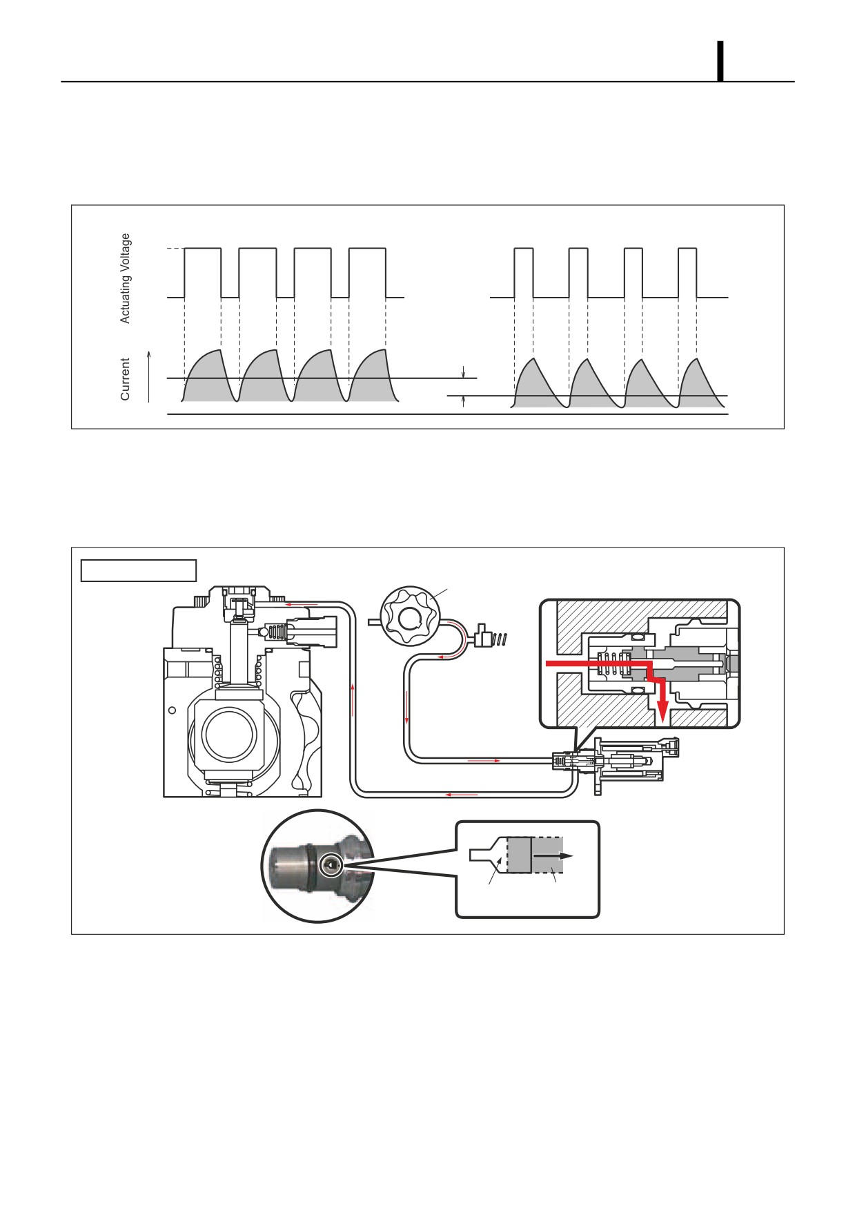
Duty Ratio Control
- The engine ECU outputs sawtooth wave signals with a constant frequency. The value of the current is the effective
(average) value of these signals. As the effective value increases, the valve opening decreases, and as the effec-
tive value decreases, the valve opening increases.
Low Suction Quantity
High Suction Quantity
ON
OFF
Average Current Difference
QD0710E
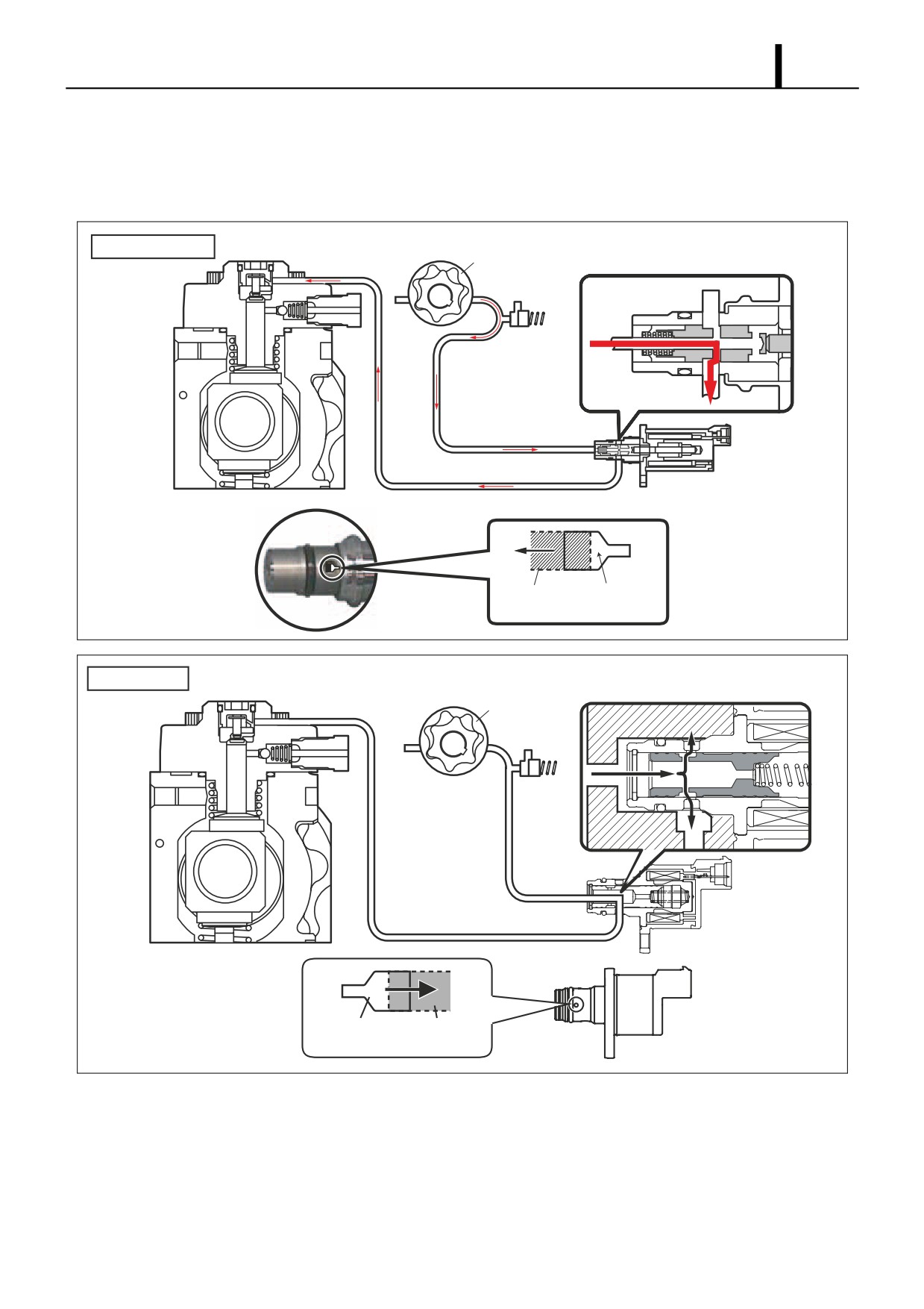
When the SCV Energized Duration (Duty ON Time) is Short
- When the SCV energization time is short, the average current flowing through the solenoid is small. As a result, the
needle valve is returned by spring force, creating a large valve opening. Subsequently, the fuel suction quantity
increases.
Conventional SCV
Feed Pump
SCV
Large Valve Needle
Opening
Valve
Q002341E
Operation Section
1-32
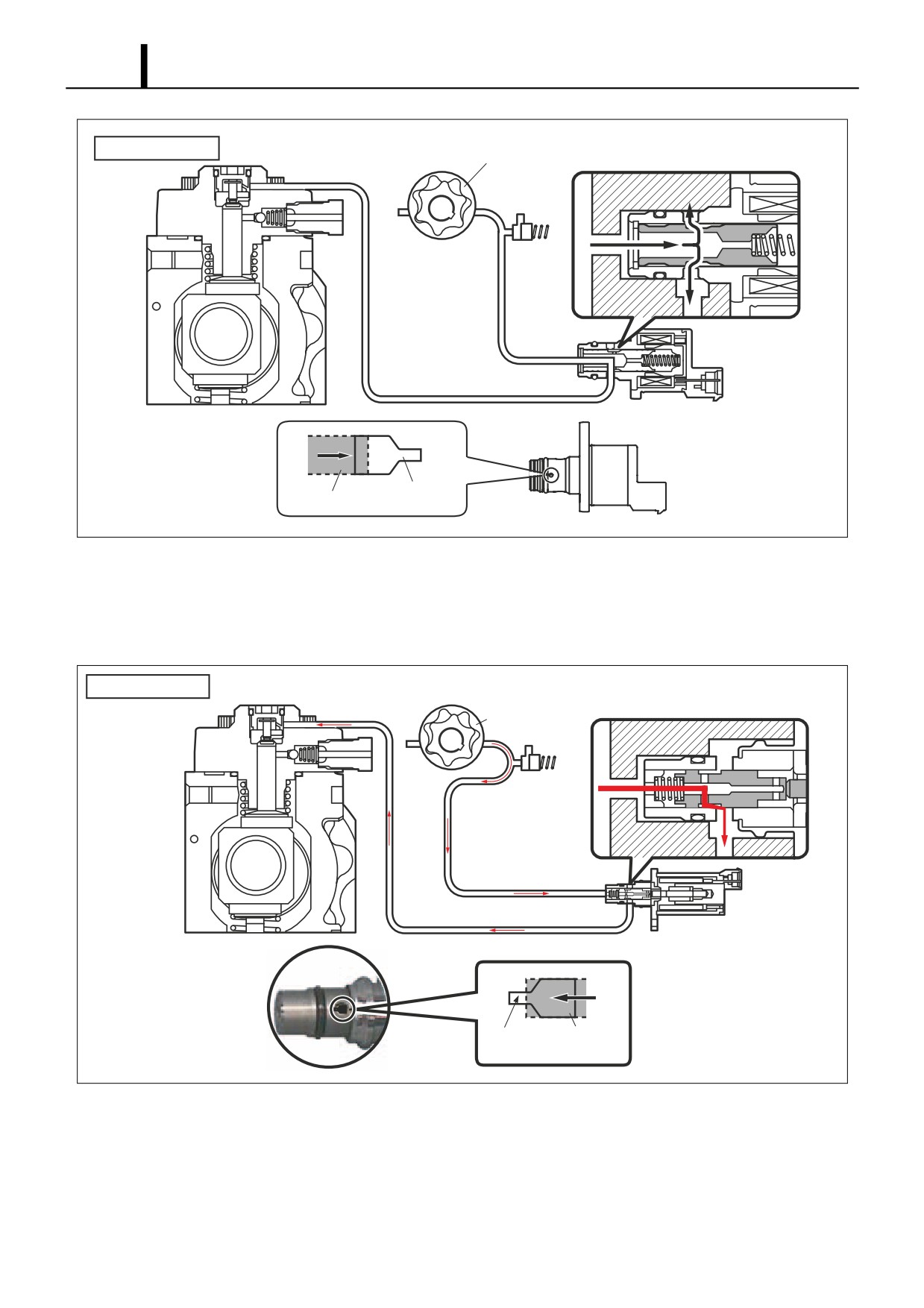
Compact SCV
Feed Pump
Large
Needle Valve
Opening
Q002321E
When the SCV Energized Duration (Duty ON Time) is Long
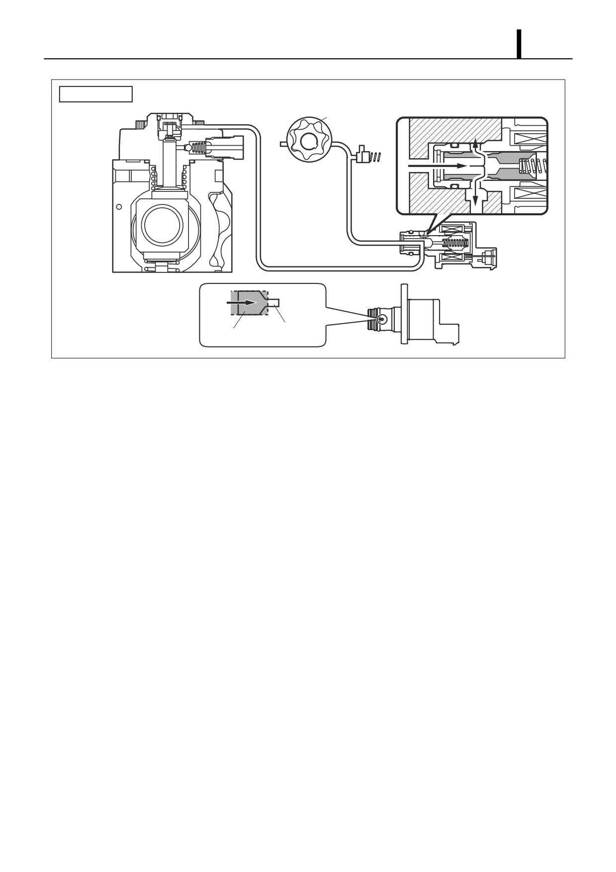
- When the energization time is long, the average current flowing to the solenoid is large. As a result, the needle
valve is pressed out (in the compact SCV, the needle valve is pulled), creating a small valve opening. Subsequently,
the fuel suction quantity decreases.
Conventional SCV
SCV
Feed Pump
Small
Needle
Opening
Valve
Q002342E
Operation Section
1-33
Compact SCV
SCV
Feed Pump
Small Valve
Needle Valve
Opening
Q002322E
Operation Section
1-34
Normally Closed Type
- When the solenoid is energized, the needle valve is pressed upon (in the compact SCV, the cylinder is pulled upon)
by the armature, completely opening the fuel passage and supplying fuel to the plunger. (Total quantity suctioned
→ Total quantity discharged)
- When power is removed from the solenoid, the return spring presses the needle valve back to the original position,
closing the fuel passage.
- The solenoid ON/OFF is actuated by duty ratio control. Fuel is supplied in an amount corresponding to the open
surface area of the passage, which depends on the duty ratio, and then is discharged by the plungers.
Conventional SCV
Return Spring
Solenoid
Valve Body
Needle Valve
External View
Cross Section
Q002343E
Compact SCV
Valve Body
Solenoid
Return Spring
Needle Valve
External View
Cross Section
Q002323E
Duty Ratio Control
- The engine ECU outputs sawtooth wave signals with a constant frequency. The value of the current is the effective
(average) value of these signals. As the effective value increases, the valve opening increases, and as the effective
value decreases, the valve opening decreases.
High Suction Quantity
Low Suction Quantity
ON
OFF
Average Current Difference
Q000844E
Operation Section
1-35
When the SCV Energized Duration (Duty ON Time) is Long
- When the energization time is long, the average current flowing to the solenoid is large. As a result, the needle
valve is pushed out (in the compact SCV, the needle valve is pulled), creating a large valve opening. Subsequently,
the fuel suction quantity increases.
Conventional SCV
Feed Pump
SCV
Needle
Large
Valve
Opening
Q002344E
Compact SCV
SCV
Feed Pump
Large Valve
Needle
Opening
Valve
Q002324 E
//////////////////////