DENSO COMMON RAIL SYSTEM (CRS). SERVICE MANUAL (2007) - page 2
Operation Section
1-36
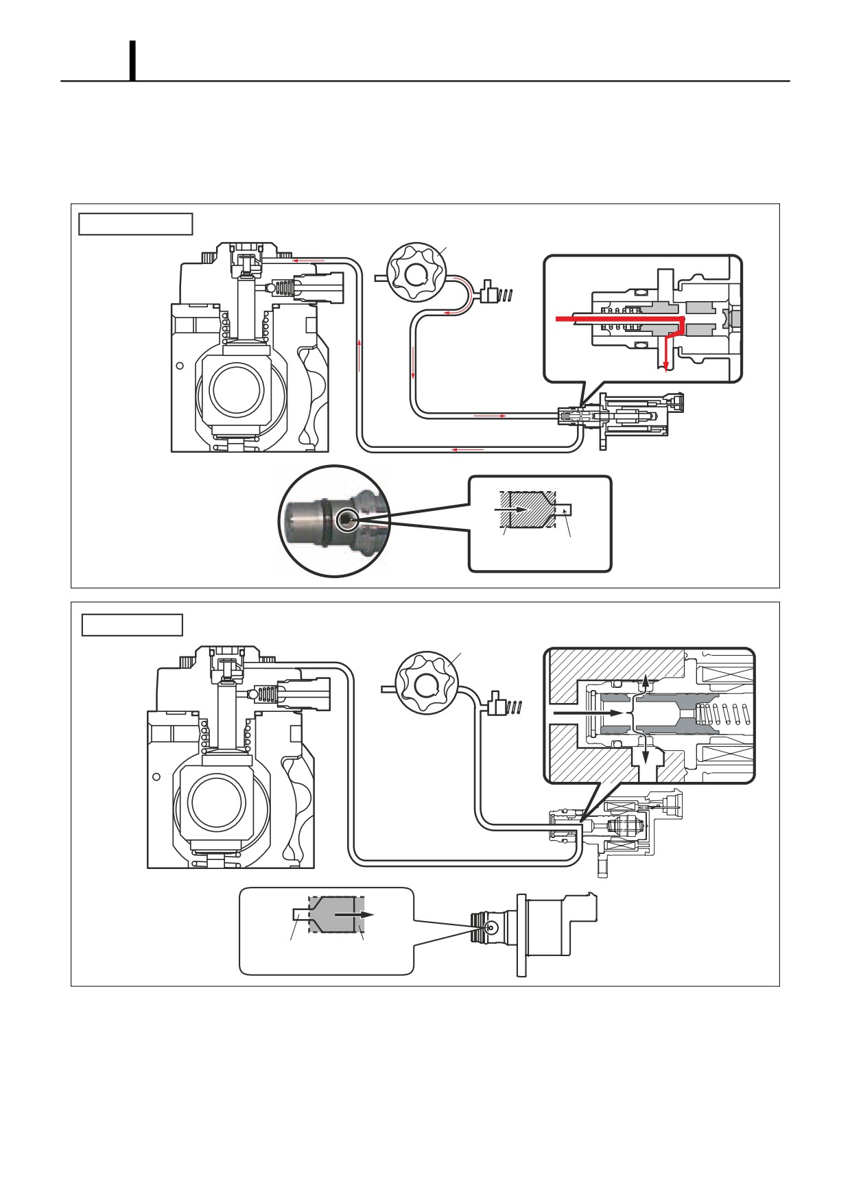
When the SCV Energized Duration (Duty ON Time) is Short
- When the energization time is short, the average current flowing through the solenoid is small. As a result, the nee-
dle valve is returned to the original position by spring force, creating a small valve opening. Subsequently, the fuel
suction quantity decreases.
Conventional SCV
Feed Pump
SCV
Needle
Small
Valve
Opening
Q002345E
Compact SCV
SCV
Feed Pump
Small Valve
Needle
Opening
Valve
Q002325E
Operation Section
1-37
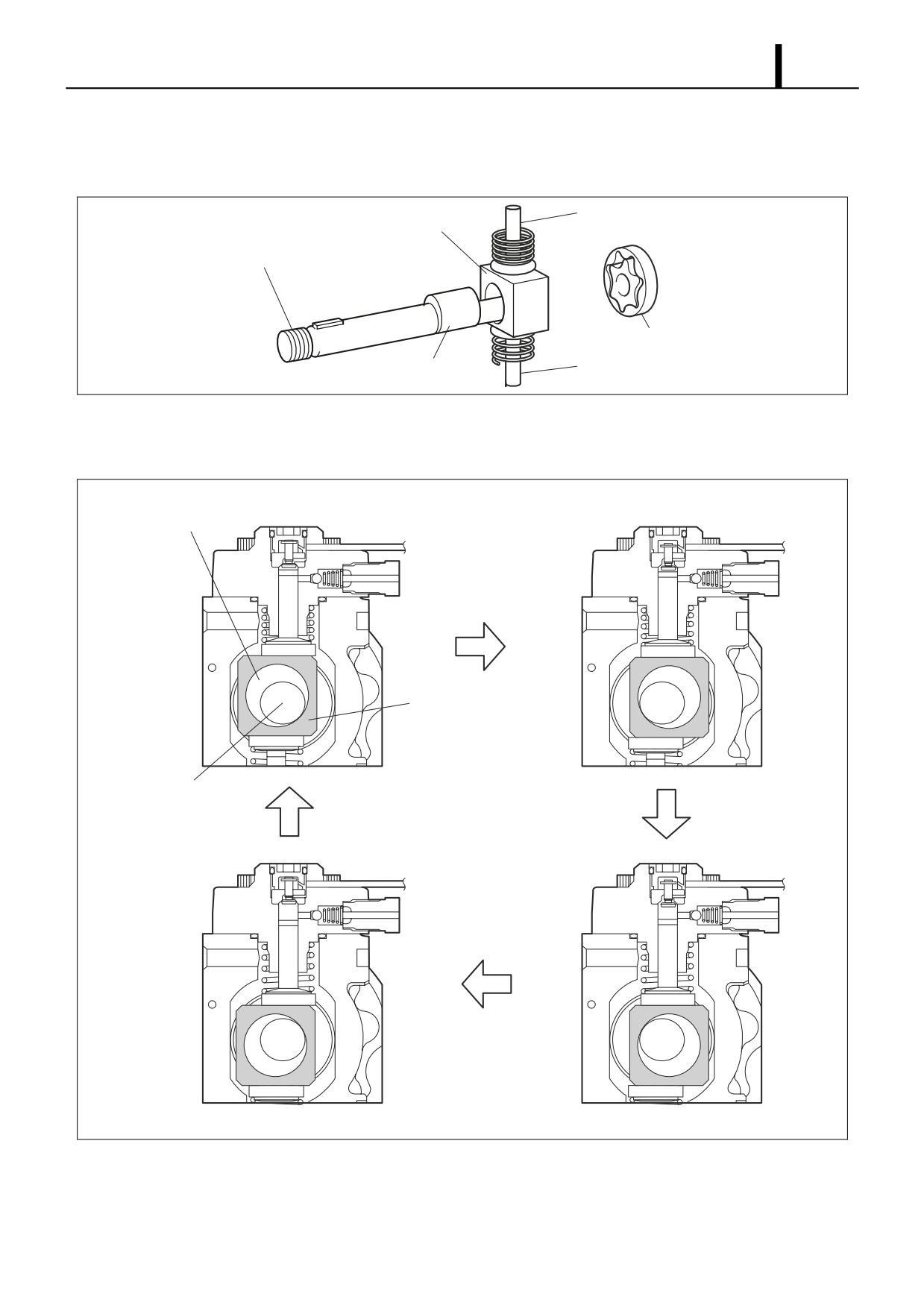
Pump Unit (Eccentric Cam, Ring Cam, Plunger)
• The eccentric cam is attached to the camshaft and the ring cam is installed on the eccentric cam. There are two plung-
ers at positions symmetrical above and below the ring cam.
Plunger A
Ring Cam
Camshaft
Feed Pump
Eccentric Cam
Plunger B
Q000845E
• Because the rotation of the camshaft makes the eccentric cam rotate eccentrically, the ring cam follows this and
moves up and down, and this moves the two plungers reciprocally. (The ring cam itself does not rotate.)
Eccentric Cam
Ring Cam
Camshaft
Q000846E
Operation Section
1-38
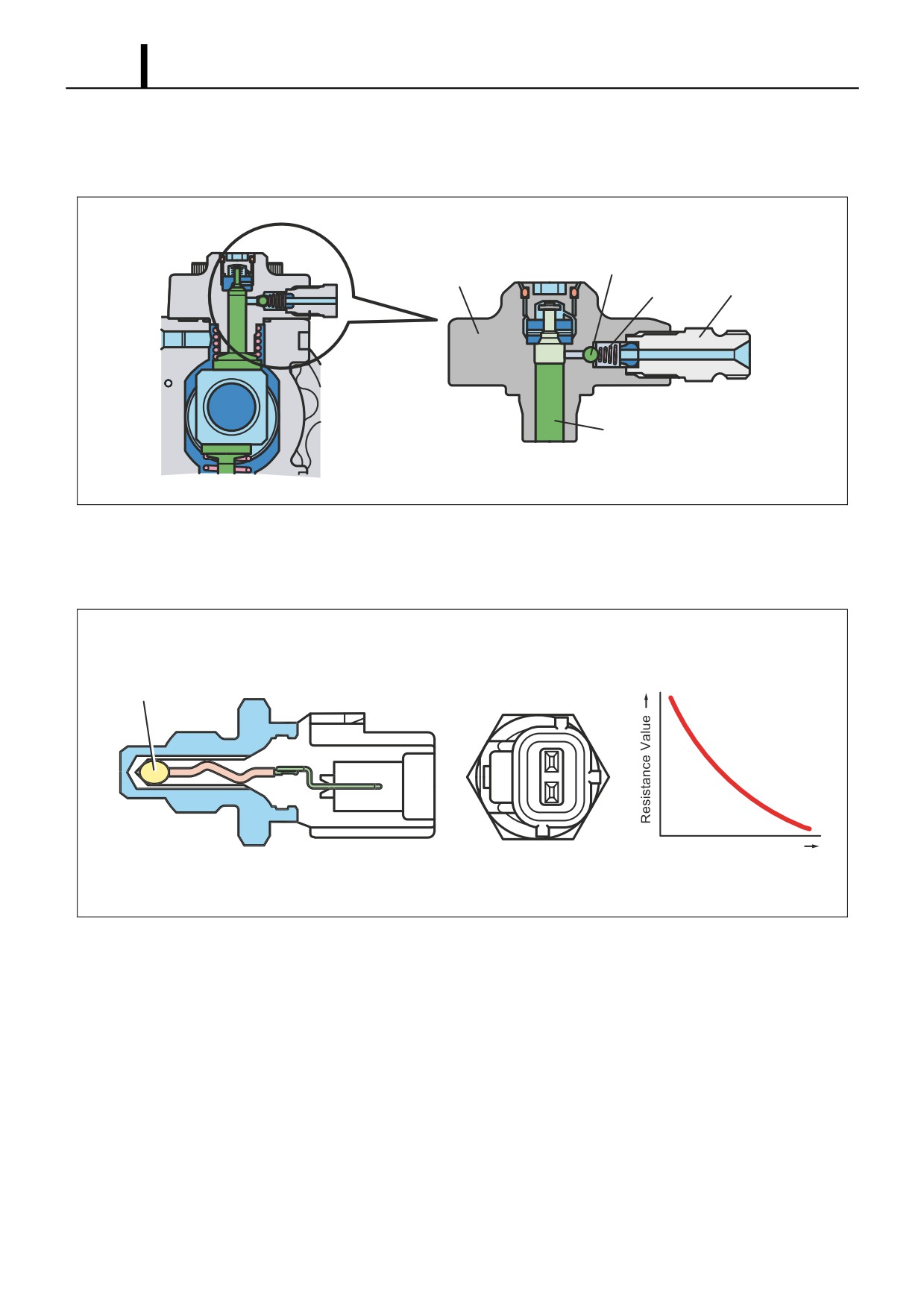
Delivery Valve
• The delivery valve for the HP3 has an integrated element and is made up of the check ball, spring, and holder. When
the pressure at the plunger exceeds the pressure in the rail, the check ball opens to discharge the fuel.
Check Ball
Element
Spring
Holder
Plunger
Q000847E
Fuel Temperature Sensor
• The fuel temperature sensor is installed on the fuel intake side and utilizes the characteristics of a thermistor in which
the electric resistance changes with the temperature in order to detect the fuel temperature.
Resistance - Temperature
Thermistor
Characteristic
Temperature
Q000848E
Operation Section
1-39
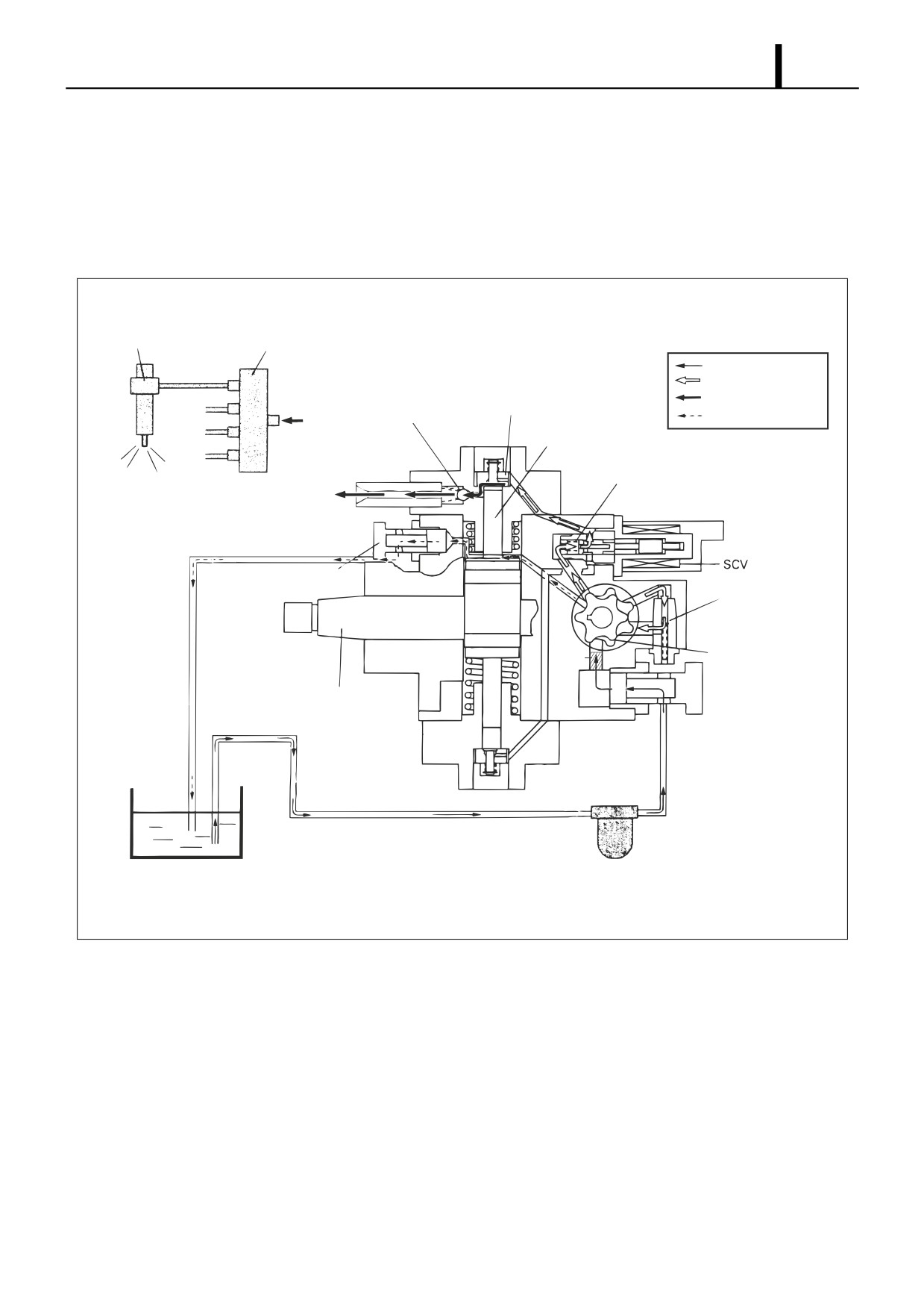
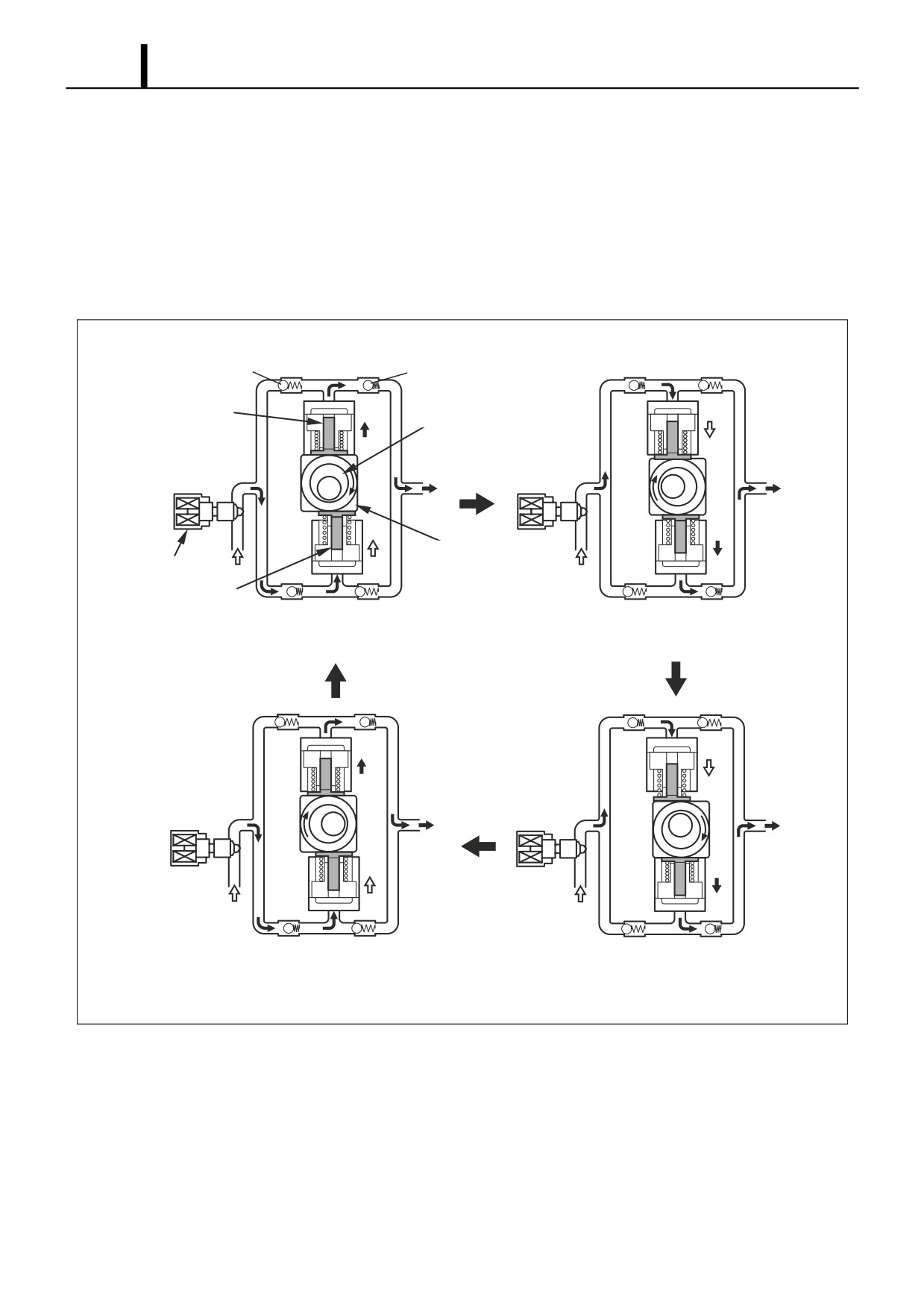
(4) Supply Pump Operation
Supply Pump Overall Fuel Flow
• The fuel is suctioned by the feed pump from the fuel tank and sent to the SCV. At this time, the regulating valve adjusts
the fuel pressure to below a certain level. The fuel sent from the feed pump has the required discharge quantity ad-
justed by the SCV, and enters the pump unit through the suction valve. The fuel pumped by the pump unit is pumped
through the delivery valve to the rail.
Inject
Rail
Suction Pressure
Feed Pressure
High Pressure
Suction Valve
Discharge Valve
Return Pressure
From Pump
Plunger
Return Spring
To Rail
Return
Combustion Overflow
Regulating Valve
Feed Pump
Filter
Fuel Intake Port
Camshaft
Suction
Fuel Filter
(With Priming Pump)
Fuel Tank
Q000849E
Operation Section
1-40
Operation
• The discharge quantity is controlled by SCV control, the same as for the HP2, however it differs from the HP2 in that
the valve opening is adjusted by duty ratio control.
• In the intake stroke, the spring makes the plunger follow the movement of the ring cam, so the plunger descends to-
gether with the ring cam. Thus, unlike the HP2, the plunger itself also suctions in fuel. When the suctioned fuel passes
through the SCV, the flow quantity is controlled to the required discharge quantity by the valve opening and enters
the pump main unit.
• The quantity of fuel adjusted by the SCV is pumped during the pumping stroke.
Suction Valve
Delivery Valve
Plunger A
Eccentric Cam
Ring Cam
SCV
Plunger B
Plunger A: End of Compression
Plunger A: Start of Suction
Plunger B: End of Suction
Plunger B: Start of Compression
Plunger A: Start of Compression
Plunger A: End of Suction
Plunger B: Start of Suction
Plunger B: End of Compression
QD0707E
Operation Section
1-41
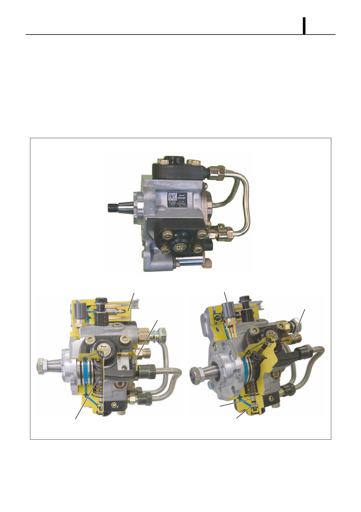
3.4 HP4 Type
(1) Construction and Characteristics
• The HP4 basic supply pump construction is the same as for the HP3. The composition is also the same as the HP3,
being made up of the pump unit (eccentric cam, ring cam, plunger), the SCV (suction control valve), the fuel temper-
ature sensor, and the feed pump. The main difference is that there are three plungers.
• Because there are three plungers, they are positioned at intervals of 120? around the outside of the ring cam. In ad-
dition, the fuel delivery capacity is 1.5 times that of the HP3.
• The fuel discharge quantity is controlled by the SCV, the same as for the HP3.
SCV (Suction Control Valve)
Fuel Temperature Sensor
Delivery Valve
Feed Pump
Plunger
Suction Valve
Eccentric Cam
Q000850E
Operation Section
1-42
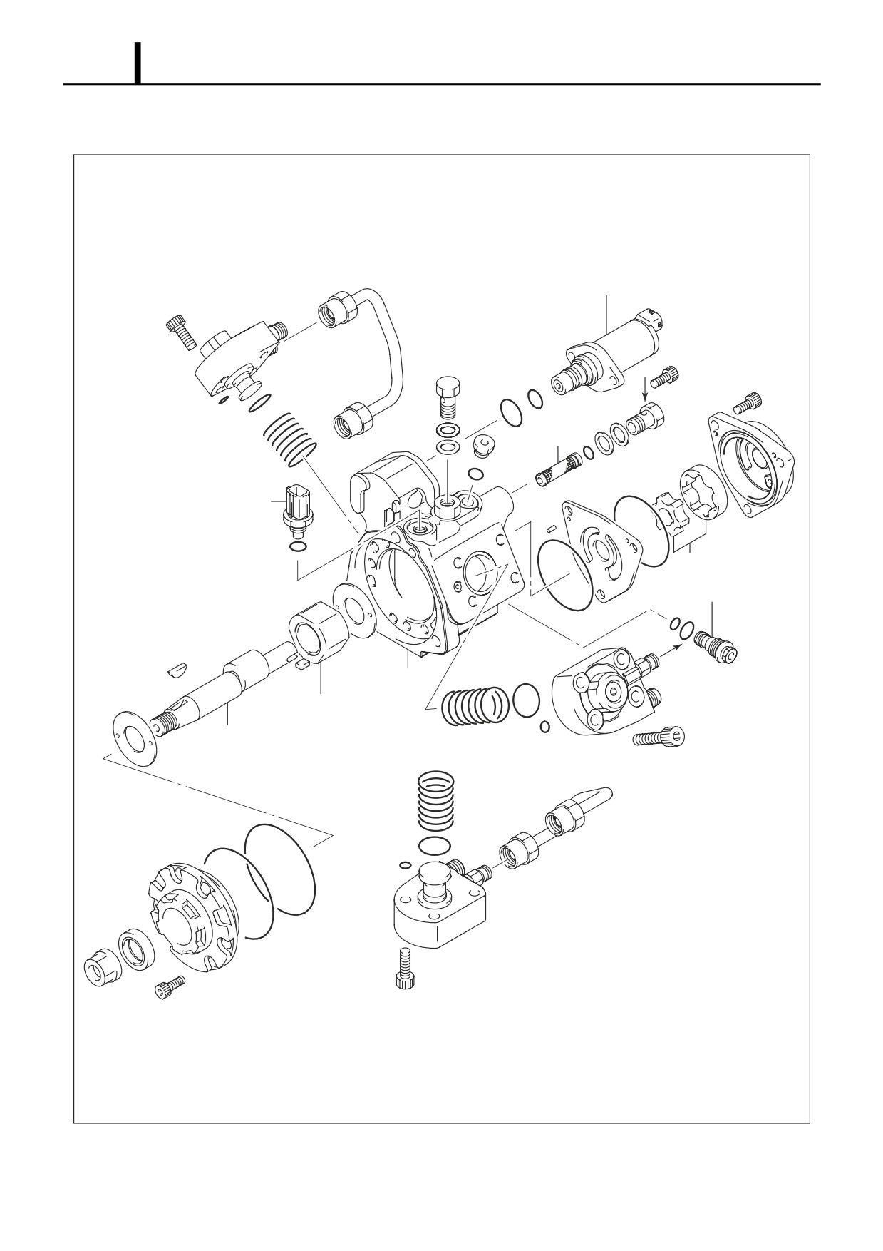
(2) Exploded View
SCV
IN
Filter
Fuel Temperature Sensor
Feed Pump
Regulating Valve
OUT
Pump Body
Ring Cam
Camshaft
Q000457E
Operation Section
1-43
(3) Component Part Functions
Component Parts
Functions
Feed Pump
Draws fuel from the fuel tank and feeds it to the plunger.
Regulating Valve
Regulates the pressure of the fuel in the supply pump.
SCV (Suction Control Valve)
Controls the quantity of fuel that is fed to the plungers.
Eccentric Cam
Actuates the ring cam.
Pump Unit
Ring Cam
Actuates the plunger.
Plunger
Moves reciprocally to draw and compress fuel.
Suction Valve
Prevents reverse flow of compressed fuel into the SCV.
Delivery Valve
Prevents reverse flow from the rail of the fuel pumped from the plunger.
Fuel Temperature Sensor
Detects the fuel temperature.
• The HP4 supply pump component parts and functions are basically the same as for the HP3. The explanations below
only cover those points on which the HP4 differs from the HP3. For other parts, see the appropriate item in the expla-
nation of the HP3.
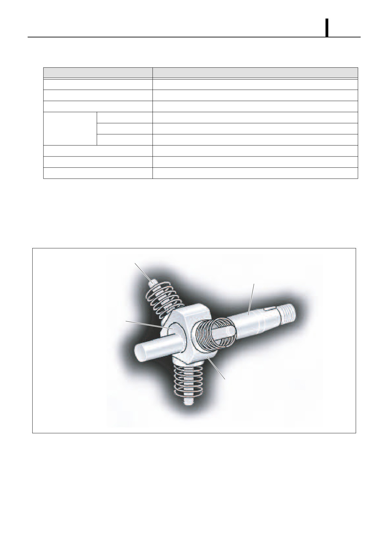
Pump Unit (Eccentric Cam, Ring Cam, Plunger)
• A triangular ring cam is installed on the eccentric cam on the drive shaft, and three plungers are installed to the ring
cam at intervals of 120°.
Plunger
Camshaft
Eccentric Cam
Ring Cam
Q000851E
Operation Section
1-44
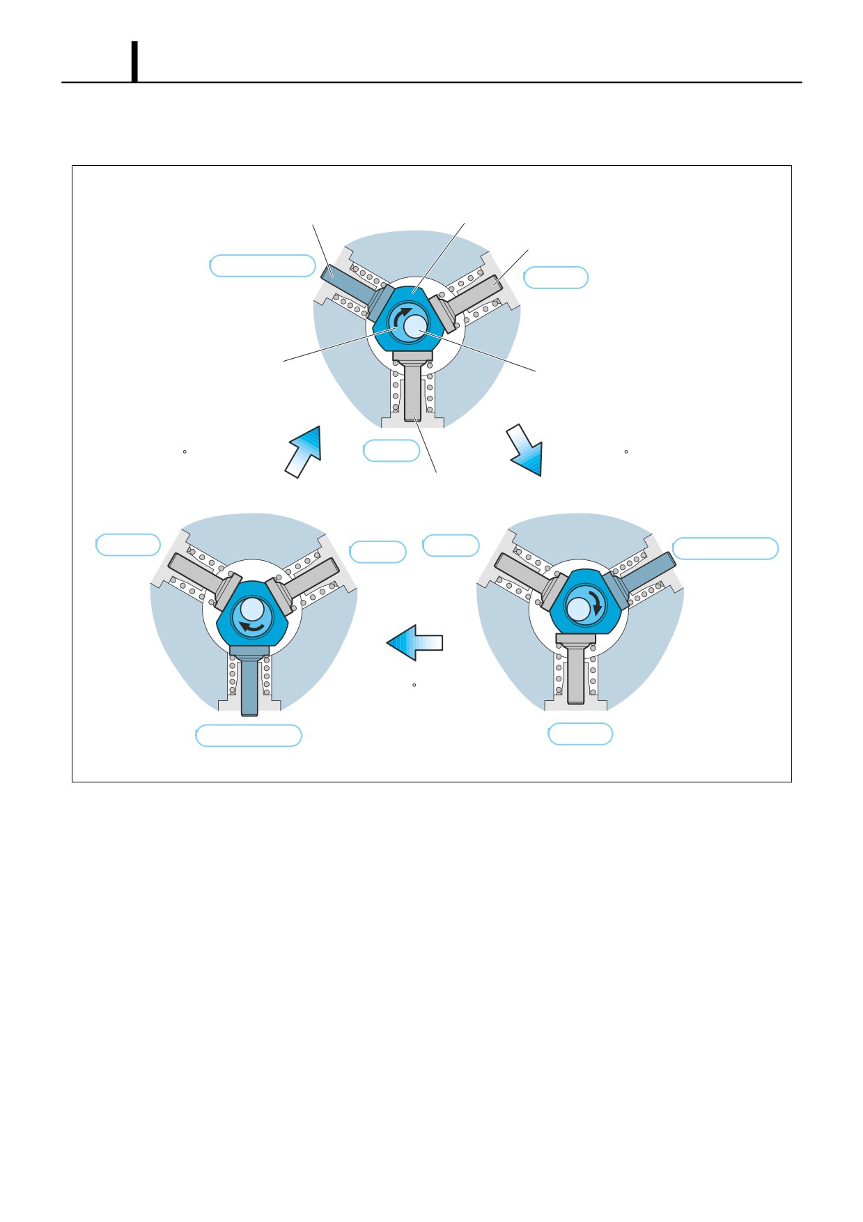
• Because the rotation of the camshaft makes the eccentric cam rotate eccentrically, the ring cam follows this and this
moves the three plungers reciprocally. (The ring cam itself does not rotate.)
Plunger #1
Ring Cam
Plunger #2
End of Pumping
Pumping
Eccentric Cam
Camshaft
Camshaft
Camshaft
Suction
Rotate 120 Clockwise
Rotate 120 Clockwise
Plunger #3
Pumping
Suction
End of Pumping
Suction
Camshaft
Rotate 120 Clockwise
End of Pumping
Pumping
D000852E
Operation Section
1-45
(4) Supply Pump Operation
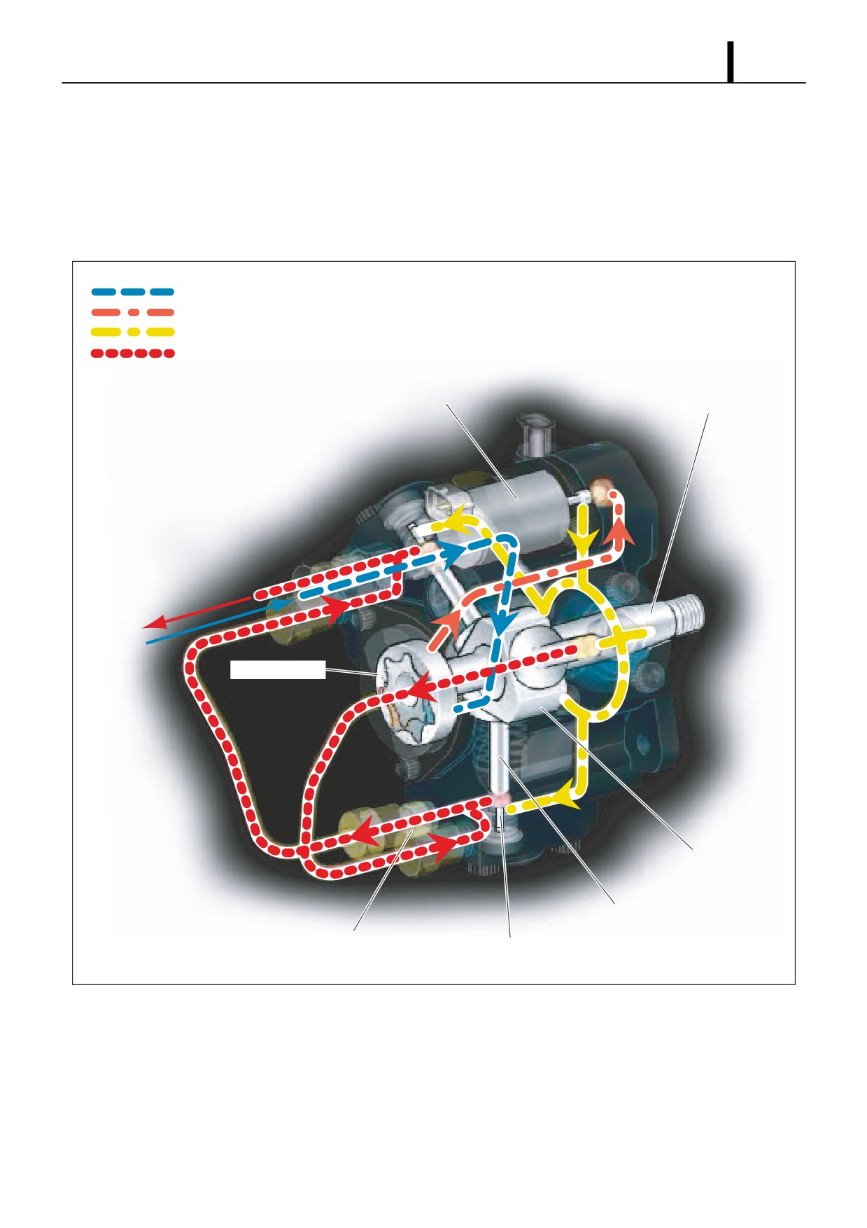
Supply Pump Overall Fuel Flow
• The fuel is suctioned by the feed pump from the fuel tank and sent to the SCV. At this time, the regulating valve adjusts
the fuel pressure to below a certain level. The fuel sent from the feed pump has the required discharge quantity ad-
justed by the SCV, and enters the pump unit through the suction valve. The fuel pumped by the pump unit is pumped
through the delivery valve to the rail.
Feed Pump from Fuel Tank (Suction)
SCV from Feed Pump (Low Pressure)
Pump Unit from SCV (Low-Pressure Adjustment Complete)
From Pump Unit to Rail (High Pressure)
SCV
Camshaft
To Rail
From Fuel
Tank
Feed Pump
Ring Cam
Plunger
Delivery Valve
Suction Valve
Q000853E
Operation
• The discharge quantity is controlled by the SCV. As with the HP3, the valve opening is adjusted by duty ratio control.
The only difference from the HP3 is the shape of the pump unit. Operation and control are basically the same. For
details on operation and control, see the explanation of the HP3.
Operation Section
1-46
4. RAIL DESCCRIPTION
4.1 Rail Functions and Composition
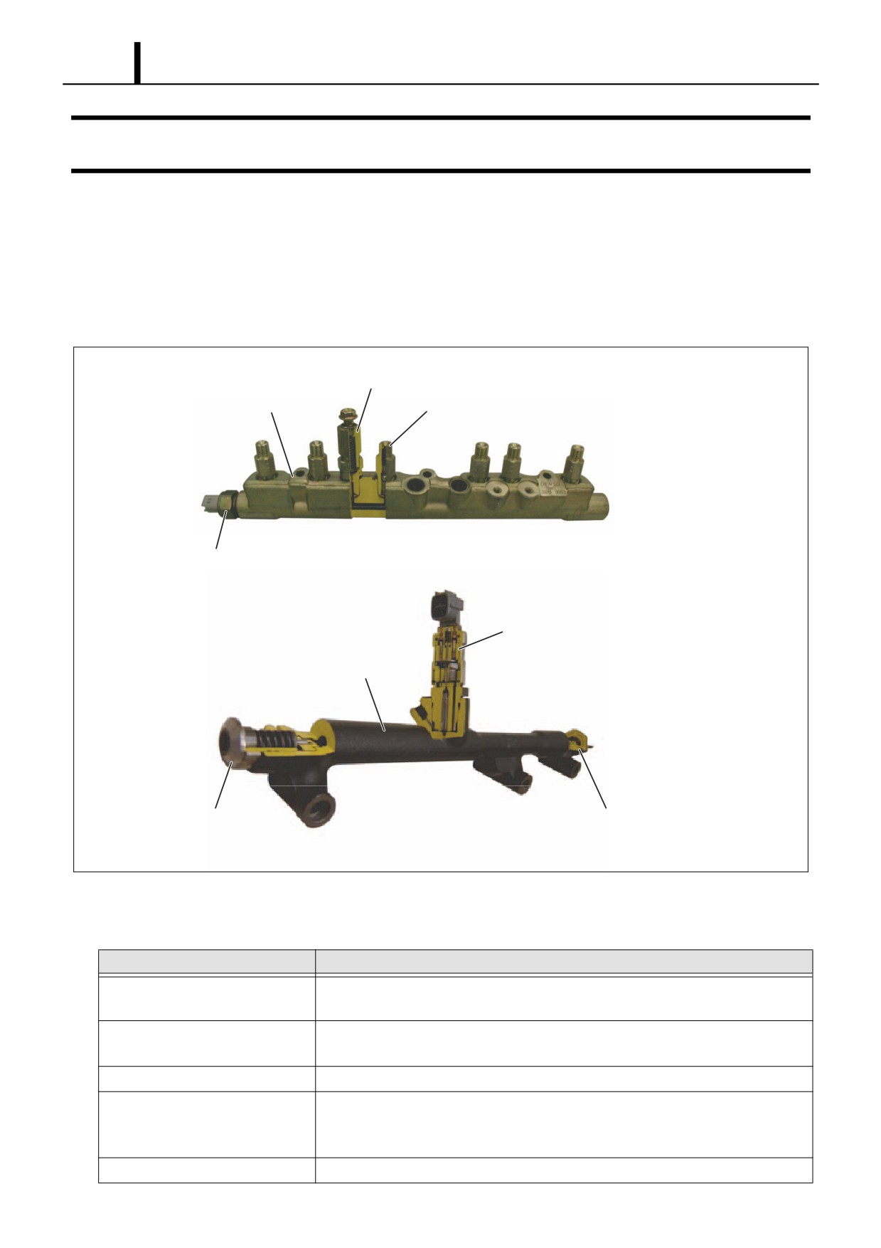
z The function of the rail is to distribute fuel pressurized by the supply pump to each cylinder injector.
z The shape of the rail depends on the model and the component parts vary accordingly.
z The component parts are the rail pressure sensor (Pc sensor), pressure limiter, and for some models a flow damper and
pressure discharge valve.
Pressure Limiter
Rail
Flow Damper
Rail Pressure Sensor (Pc Sensor)
Pressure Discharge Valve
Rail
Pressure Limiter
Rail Pressure Sensor (Pc Sensor)
Q000854E
4.2 Component Part Construction and Operation
Component Parts
Functions
Rail
Stores pressurized fuel that has been pumped from the supply pump and distrib-
utes the fuel to each cylinder injector.
Pressure Limiter
Opens the valve to release pressure if the pressure in the rail becomes abnormally
high.
Rail Pressure Sensor (Pc Sensor)
Detects the fuel pressure in the rail.
Flow Damper
Reduces the pressure pulsations of fuel in the rail. If fuel flows out excessively, the
damper closes the fuel passage to prevent further flow of fuel. Mostly used with
engines for large vehicles.
Pressure Discharge Valve
Controls the fuel pressure in the rail. Mostly used with engines for passenger cars.
Operation Section
1-47
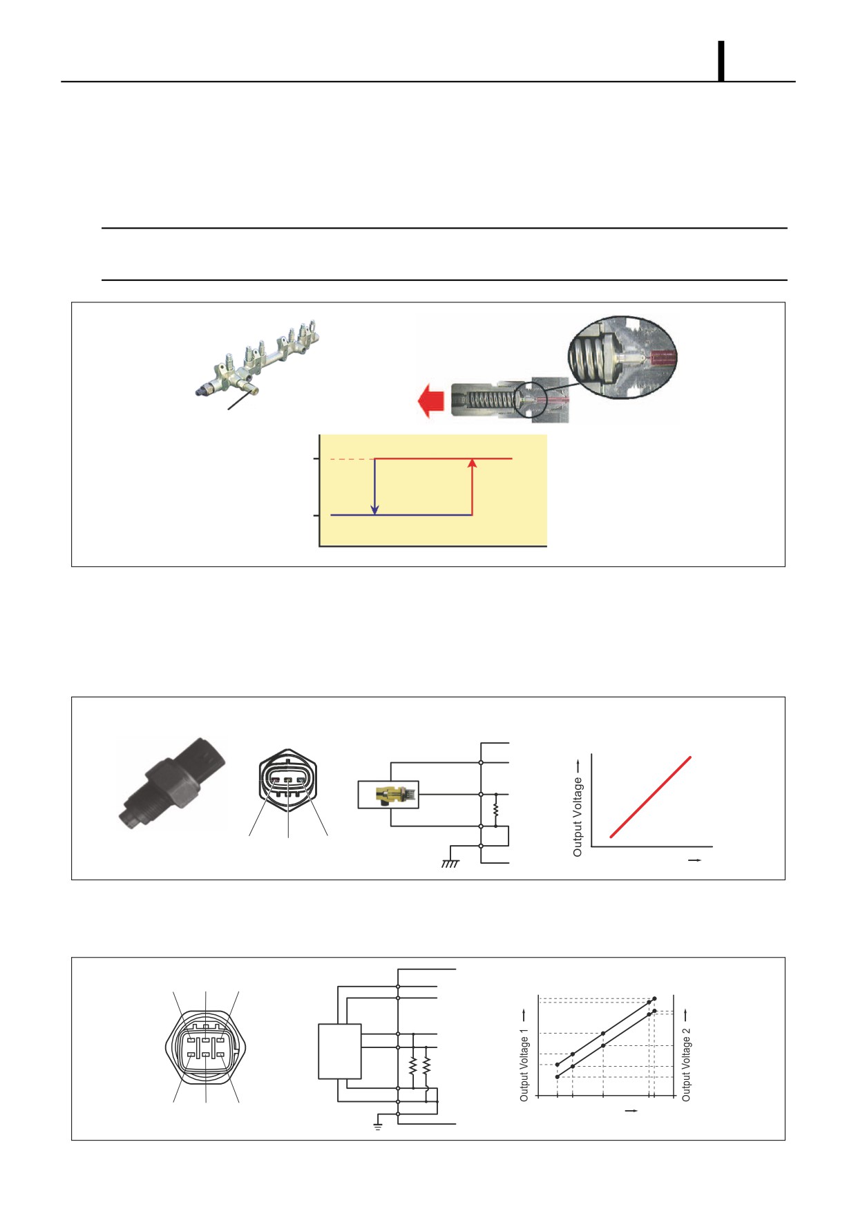
(1) Pressure Limiter
• The pressure limiter opens to release the pressure if abnormally high pressure is generated. If pressure within the rail
becomes abnormally high, the pressure limiter operates (opens). It resumes operation (closes) after the pressure falls
to a certain level. Fuel released by the pressure limiter returns to the fuel tank.
< NOTE >
The operating pressures for the pressure limiter depend on the vehicle model and are approximately 140-230MPa for
the valve opening pressure, and approximately 30-50MPa for the valve closing pressure.
Leak
(To Fuel Tank)
Pressure Limiter
Abnormally High Pressure
Valve Open
Valve Close
Return
Rail Pressure
Q000855E
(2)
Rail Pressure Sensor (Pc Sensor)
•
The rail pressure sensor (Pc sensor) is installed on the rail. It detects the fuel pressure in the rail and sends a signal
to the engine ECU. This is a semi-conductor sensor that uses the piezo-electric effect of the electrical resistance vary-
ing when pressure is applied to a silicon element.
Output
Common Rail
Sensor Wiring Diagram
Voltage -
Pressure Characteristic
Vout
Vcc=5V
Vcc
+5V
Vout
Pc
ECU
GND
GND Vout Vcc
Rail Pressure
Q000856E
•
There are also rail pressure sensors that have dual systems to provide a backup in case of breakdown. The output
voltage is offset.
VC
Vout/Vcc
E2S PR2 VCS
+5V
Vcc=5V
VCS
PR
ECU
PR2
Pc
ECU
Sensors
E2
E2S
VC PR E2
Rail Pressure
Q000857E
Operation Section
1-48
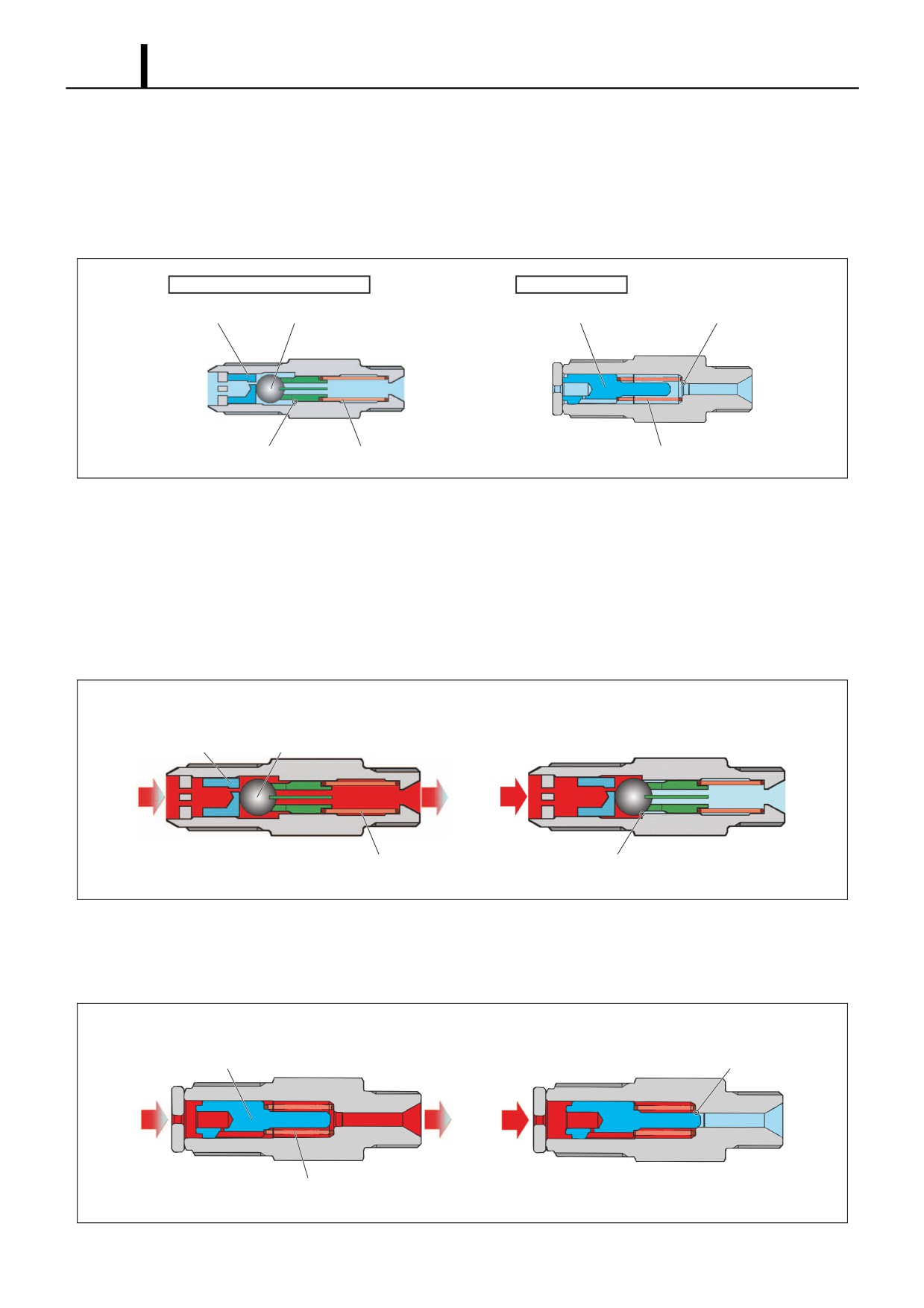
(3) Flow Damper
• The flow damper reduces the pressure pulsations of the fuel in the pressurized pipe and supplies fuel to the injectors
at a stabilized pressure. The flow damper also presents abnormal discharge of fuel by shutting off the fuel passage
in the event of excess fuel discharge, for example due to fuel leaking from an injection pipe or injector. Some flow
dampers combine a piston and ball, and some have only a piston.
Type Combining Piston and Ball
Piston-Only Type
Piston
Ball
Piston
Seat
Seat
Spring
Spring
Q000858E
Operation of Piston-and-Ball Type
- When a pressure pulse occurs in a high-pressure pipe, the resistance of it passing through the orifice disrupts the
balance between the rail side and injector side pressures, so the piston and ball move to the injector side, absorbing
the pressure pulse. With normal pressure pulses, since the rail side and injector side pressures are soon balanced,
the piston and ball are pushed back to the rail side by the spring. If there is an abnormal discharge, for example
due to an injector side fuel leak, the amount of fuel passing through the orifice cannot be balanced out and the pis-
ton presses the ball against the seat, so the passage for fuel to the injector is shut off.
· During Pressure Pulse Absorption
· Fuel Cut-Off
Piston
Ball
Spring
Seat
Q000859E
Operation of Piston-Only Type
- The piston contacts the seat directly and the piston shuts off the fuel passage directly. Operation is the same as for
the piston-and-ball type.
· During Pressure Pulse Absorption
· Fuel Cut-Off
Piston
Seat
Spring
Q000860E
Operation Section
1-49
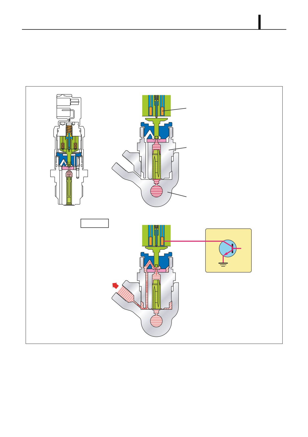
(4) Pressure Discharge Valve
• The pressure discharge valve controls the fuel pressure in the rail. When rail fuel pressure exceeds the target injection
pressure, or when the engine ECU judges that rail fuel pressure exceeds the target value, the pressure discharge
valve solenoid coil is energized. This opens the pressure discharge valve passage, allowing fuel to leak back to the
fuel tank, and reducing rail fuel pressure to the target pressure.
Solenoid Coil
Pressure Discharge Valve
Rail
Operating
ON
ECU
To Fuel tank
Q000861E
Operation Section
1-50
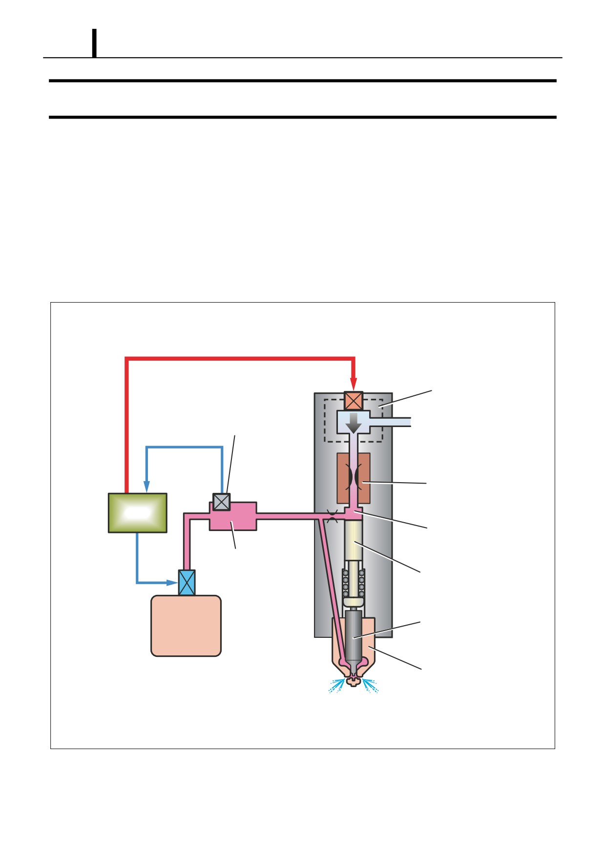
5. INJECTOR DESCRIPTION
5.1 General Description
z The injector injects the pressurized fuel in the rail into the engine combustion chamber at the optimal injection timing,
injection quantity, injection rate, and injection pattern, in accordance with signals from the ECU.
z Injection is controlled using a TWV (Two-Way Valve) and orifice. The TWV controls the pressure in the control chamber
to control the start and end of injection. The orifice controls the injection rate by restraining the speed at which the nozzle
opens.
z The command piston opens and closes the valve by transmitting the control chamber pressure to the nozzle needle.
z When the nozzle needle valve is open, the nozzle atomizes the fuel and injects it.
z There are three types of injectors: the X1, X2, and G2.
TWV
Rail Pressure Sensor
Orifice
ECU
Control Chamber Portion
Rail
Command Piston
Nozzle Needle
Supply Pump
Nozzle
Q000862E
Operation Section
1-51
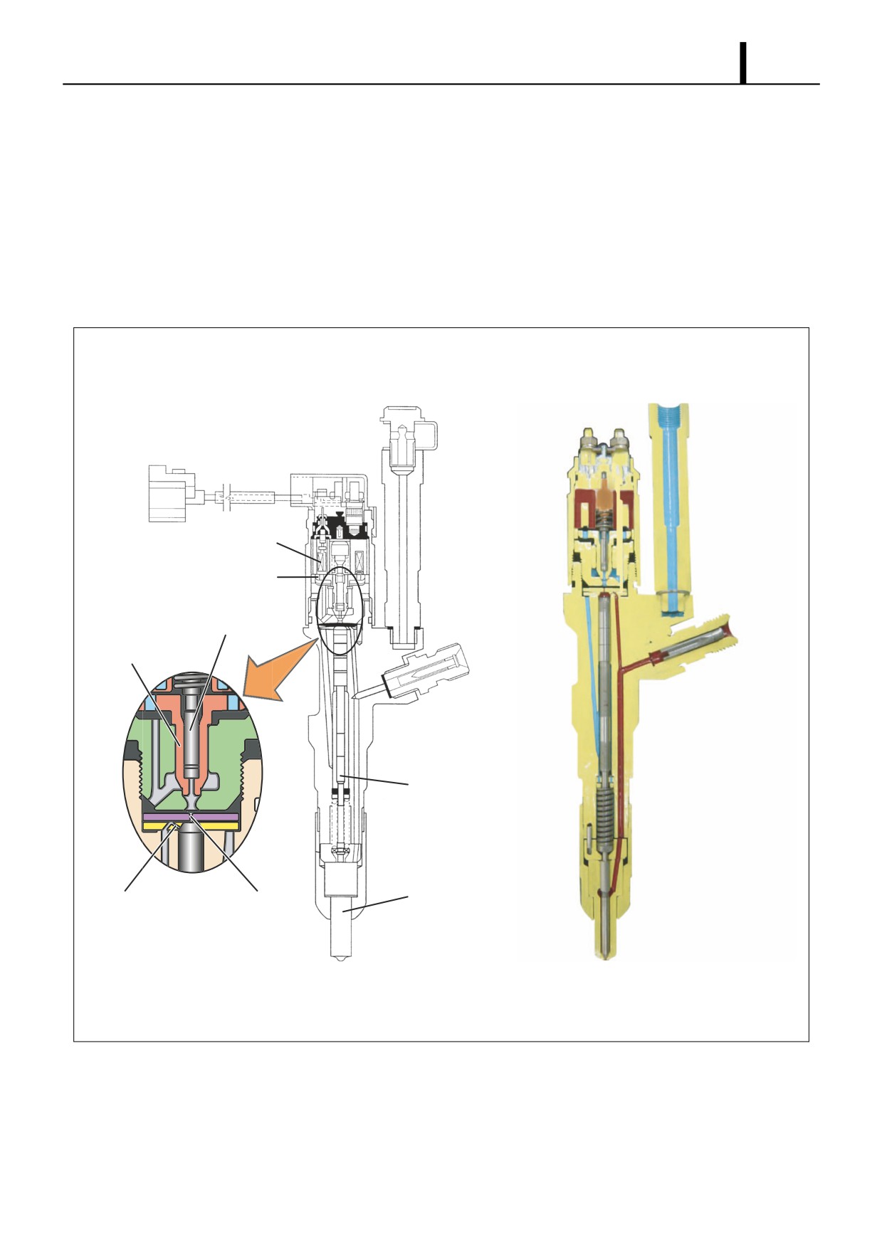
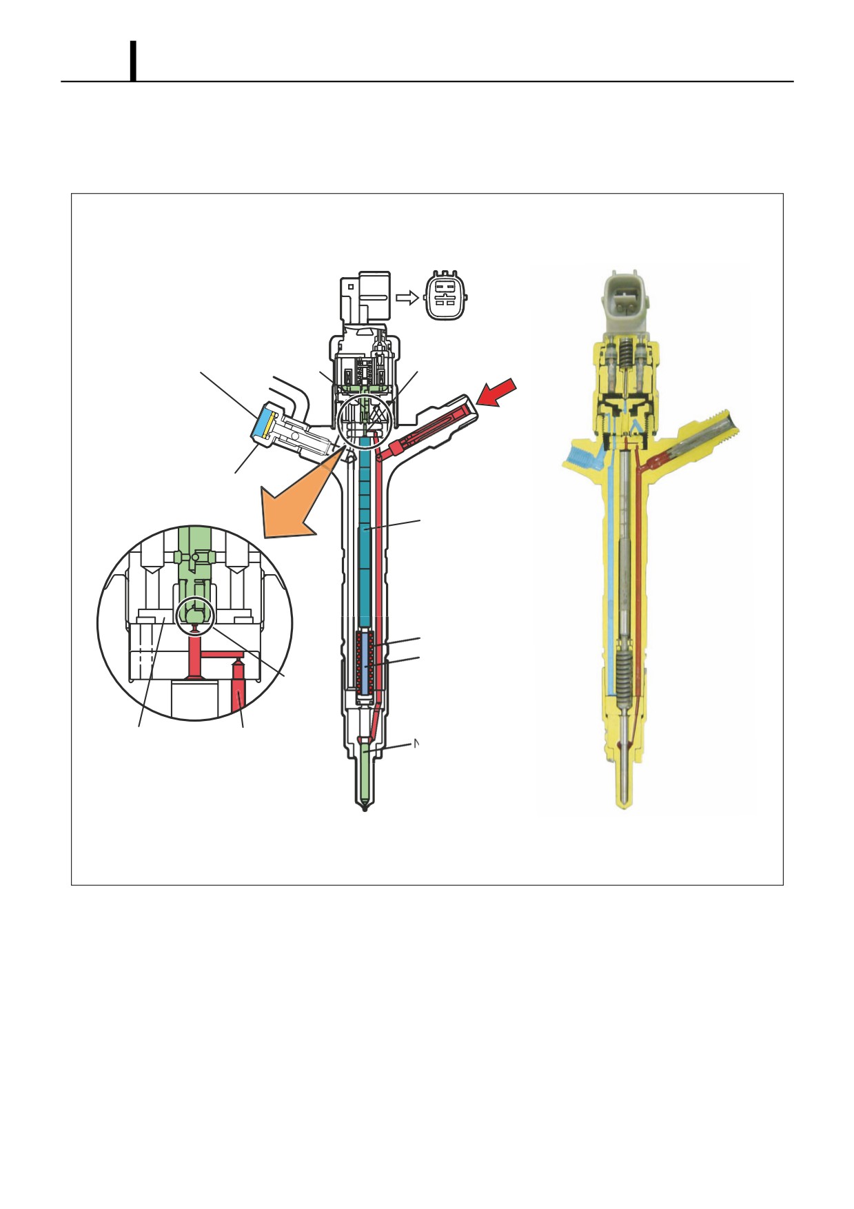
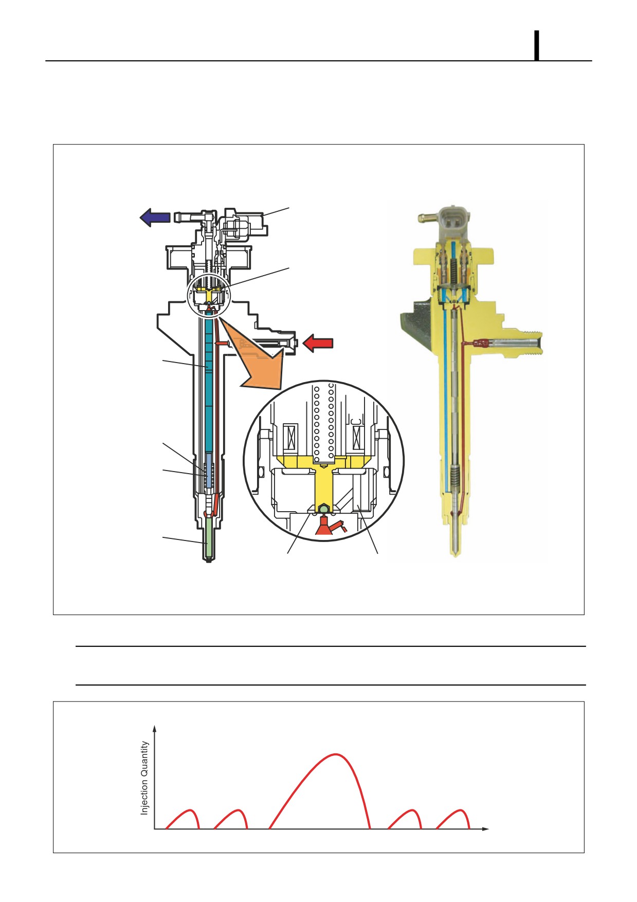
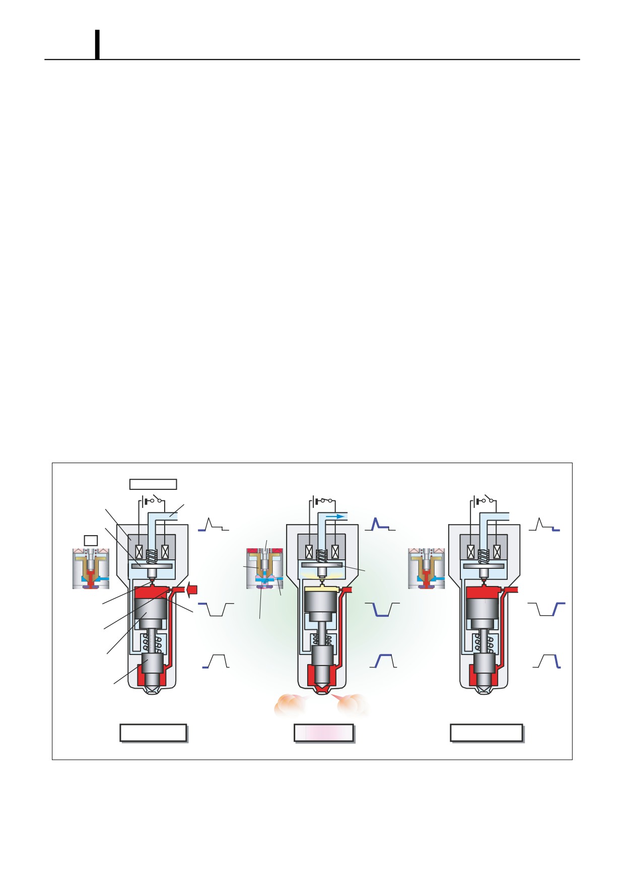
5.2 Injector Construction and Features
z The injector consists of a nozzle similar to the conventional "nozzle & nozzle holder", an orifice that controls the injection
rate, the command piston, and a TWV (two-way solenoid valve). The basic construction is the same for the X1, X2, and
G2 types.
(1) X1 Type
• Precision control is attained through electronic control of the injection. The TWV comprises two valves: the inner valve
(fixed) and the outer valve (movable).
Solenoid
TWV
Inner Valve
Outer Valve
Command Piston
Nozzle
Orifice 1
Orifice 2
Q000863E
Operation Section
1-52
(2) X2 Type
• By reducing the injector actuation load, the injector has been made more compact and energy efficient, and its injec-
tion precision has been improved. The TWV directly opens and closes the outlet orifice.
Control
Solenoid
Hollow Screw with Damper
Chamber
From Rail
Valve
O-ring
Command Piston
Nozzle Spring
Pressure Pin
Seat
Leak Passage High-Pressure Fuel
Nozzle Needle
Q000864E
Operation Section
1-53
(3) G2 Type
• To ensure high pressure, the G2 type has improved pressure strength, sealing performance and pressure wear re-
sistance. It also has improved high-speed operability, enabling higher-precision injection control and multi-injection.
To Fuel Tank
Connector
Solenoid Valve
From Rail
Command Piston
Nozzle Spring
Pressure Pin
Nozzle Needle
Seat
Leak Passage
Q000865E
< NOTE >
Multi-injection means that for the purpose of reducing exhaust gas emissions and noise, the main injection is accom-
plished with one to five injections of fuel without changing the injection quantity.
Example : Pattern with Five Injections
Main Injection
Pilot Injection Pre-Injection
After-Injection Post-Injection
Time
Q000866E
Operation Section
1-54
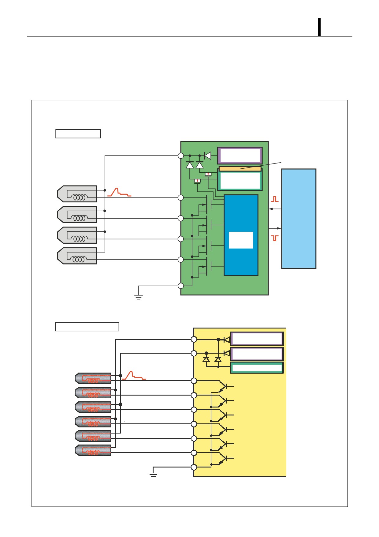
5.3 Injector Operation
z The injector controls injection through the fuel pressure in the control chamber. The TWV executes leak control of the
fuel in the control chamber to control the fuel pressure within the control chamber. The TWV varies with the injector type.
Non-Injection
• When the TWV is not energized, the TWV shuts off the leak passage from the control chamber, so the fuel pressure
in the control chamber and the fuel pressure applied to the nozzle needle are both the same rail pressure. The nozzle
needle thus closes due to the difference between the pressure-bearing surface area of the command piston and the
force of the nozzle spring, and fuel is not injected. For the X1 type, the leak passage from the control chamber is shut
off by the outer valve being pressed against the seat by the force of the spring, and the fuel pressure within the outer
valve. For the X2/G2 types, the control chamber outlet orifice is closed directly by the force of the spring.
Injection
• When TWV energization starts, the TWV valve is pulled up, opening the leak passage from the control chamber.
When this leak passage opens, the fuel in the control chamber leaks out and the pressure drops. Because of the drop
in pressure within the control chamber, the pressure on the nozzle needle overcomes the force pressing down, the
nozzle needle is pushed up, and injection starts. When fuel leaks from the control chamber, the flow quantity is re-
stricted by the orifice, so the nozzle opens gradually. The injection rate rises as the nozzle opens. As current continues
to be applied to the TWV, the nozzle needle eventually reaches the maximum amount of lift, which results in the max-
imum injection rate. Excess fuel is returned to the fuel tank through the path shown.
End of Injection
• When TWV energization ends, the valve descends, closing the leak passage from the control chamber. When the
leak passage closes, the fuel pressure within the control chamber instantly returns to the rail pressure, the nozzle
closes suddenly, and injection stops.
X2 · G2
Leak Passage
To Fuel Tank
Solenoid
TWV
Inner
Actuating
Valve
Actuating
Actuating
X1
Current
Current
Current
Outer Valve
TWV
Rail
Leak
Outlet Orifice
Passage
Control
Outlet Orifice
Control
Control
Chamber
Chamber
Chamber
Inlet Orifice
Pressure
Pressure
Pressure
Command
Piston
Injection Rate
Injection Rate
Injection Rate
Nozzle
Non-Injection
Injection
End of Injection
Q000867E
Operation Section
1-55
5.4 Injector Actuation Circuit
z In order to improve injector responsiveness, the actuation voltage has been changed to high voltage, speeding up both
solenoid magnetization and the response of the TWV. The EDU or the charge circuit in the ECU raises the respective
battery voltage to approximately 110V, which is supplied to the injector by signal from the ECU to actuate the injector.
EDU Actuation
EDU
Constant
Amperage Circuit
Charging Circuit
High Voltage
Injector
Generation Circuit
INJ#1 (No.1 Cylinder)
Actuating Current
IJt
INJ#2 (No.3 Cylinder)
ECU
INJ#3 (No.4 Cylinder)
IJf
Control
Circuit
INJ#4 (No.2 Cylinder)
ECU Direct Actuation
ECU
Common 2
Constant
Amperage Circuit
Common 1
Constant
Amperage Circuit
Injector
High Voltage Generation Circuit
2WV#1 (No.1 Cylinder)
Actuating Current
2WV#2 (No.5 Cylinder)
2WV#3 (No.3 Cylinder)
2WV#4 (No.6 Cylinder)
2WV#5 (No.2 Cylinder)
2WV#6 (No.4 Cylinder)
Q000868E
Operation Section
1-56
5.5 Other Injector Component Parts
(1) Hollow Screw with Damper
• The hollow screw with damper enhances injection quantity accuracy, by reducing the back-pressure pulsations (pres-
sure fluctuations) of the leak fuel. In addition, it minimizes the back-pressure dependence (the effect of the pressure
in the leak pipe changing the injection quantity even though the injection command is the same) of the fuel in the leak
pipe.
Hollow Screw with Damper
O-ring
Damper
O-ring
To Fuel tank
Q000869E
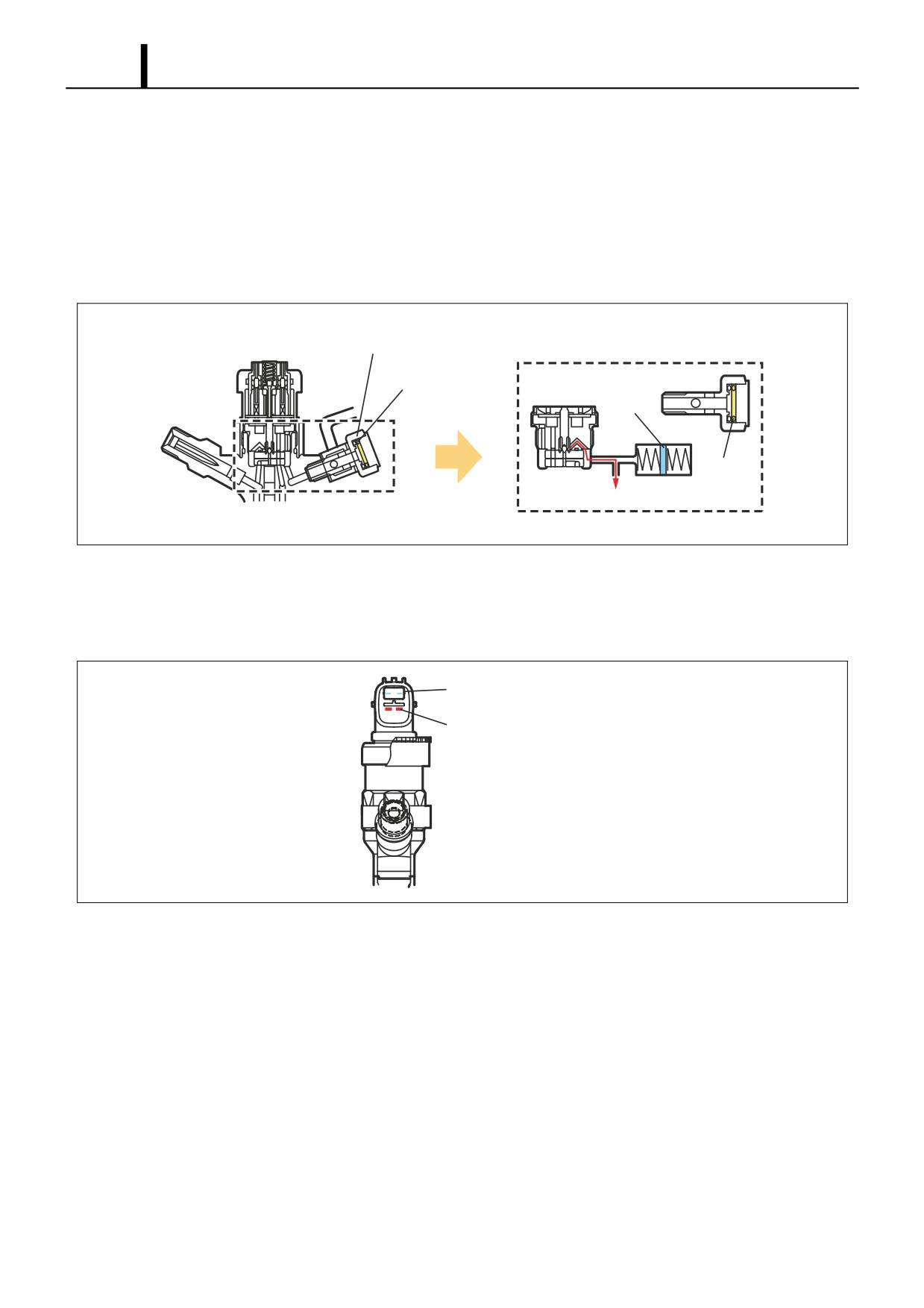
(2) Connector with Correction Resistor
• The connector with correction resistor has a built-in correction resistor in the connector section to minimize injection
quantity variation among the cylinders.
Correction Resistor Terminal
Solenoid Terminal
Q000870E
Operation Section
1-57
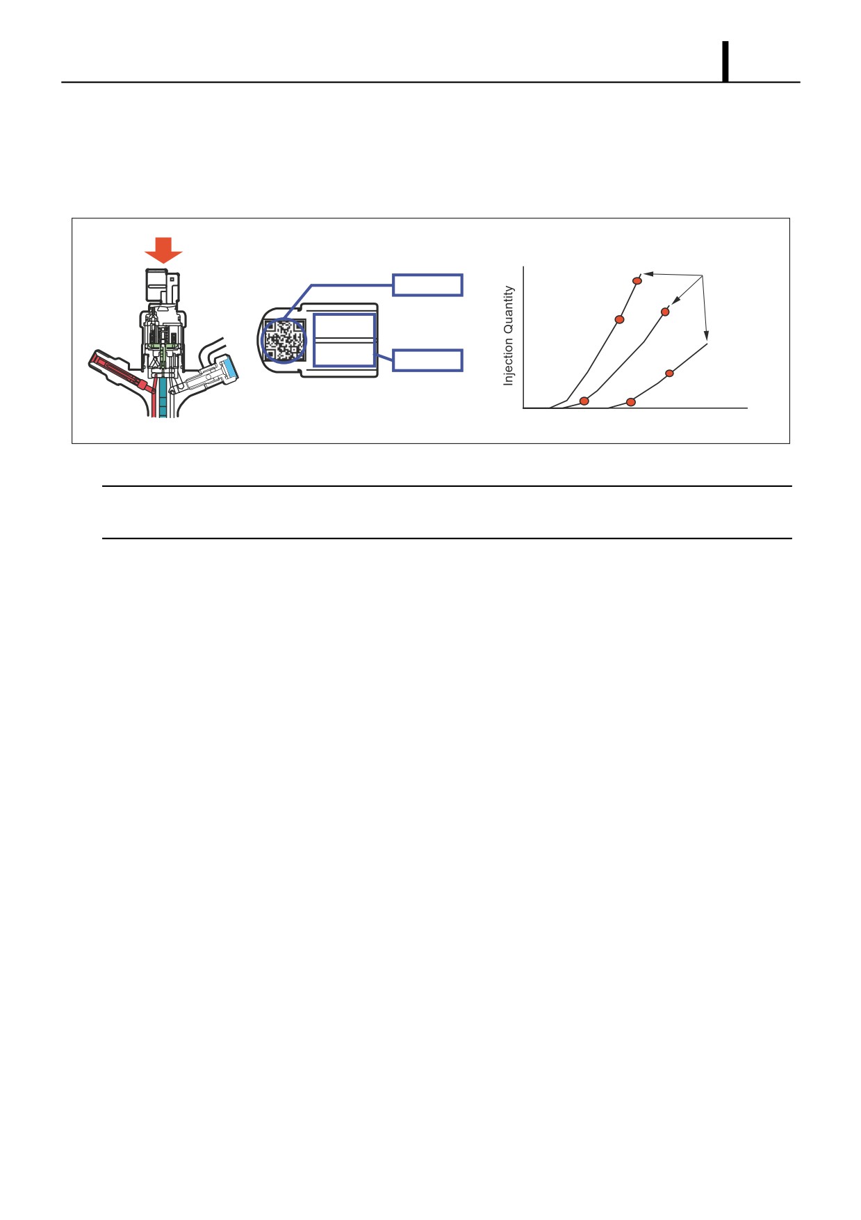
(3) Injector with QR Codes
• QR (Quick Response) codes have been adopted to enhance correction precision. The QR code, which contains the
correction data of the injector, is written to the engine ECU. QR codes have resulted in a substantial increase in the
number of fuel injection quantity correction points, greatly improving injection quantity precision.
· QR Code Correction Points (Example)
Pressure
QR Codes
Parameter
10EA01EB
13EA01EB
0300 0000
0000 BC
ID Codes
Actuating Pulse Width TQ
Q000871E
< NOTE >
QR codes are a new two-dimensional code that was developed by DENSO. In addition to injection quantity correction
data, the code contains the part number and the product number, which can be read at extremely high speeds.
Operation Section
1-58
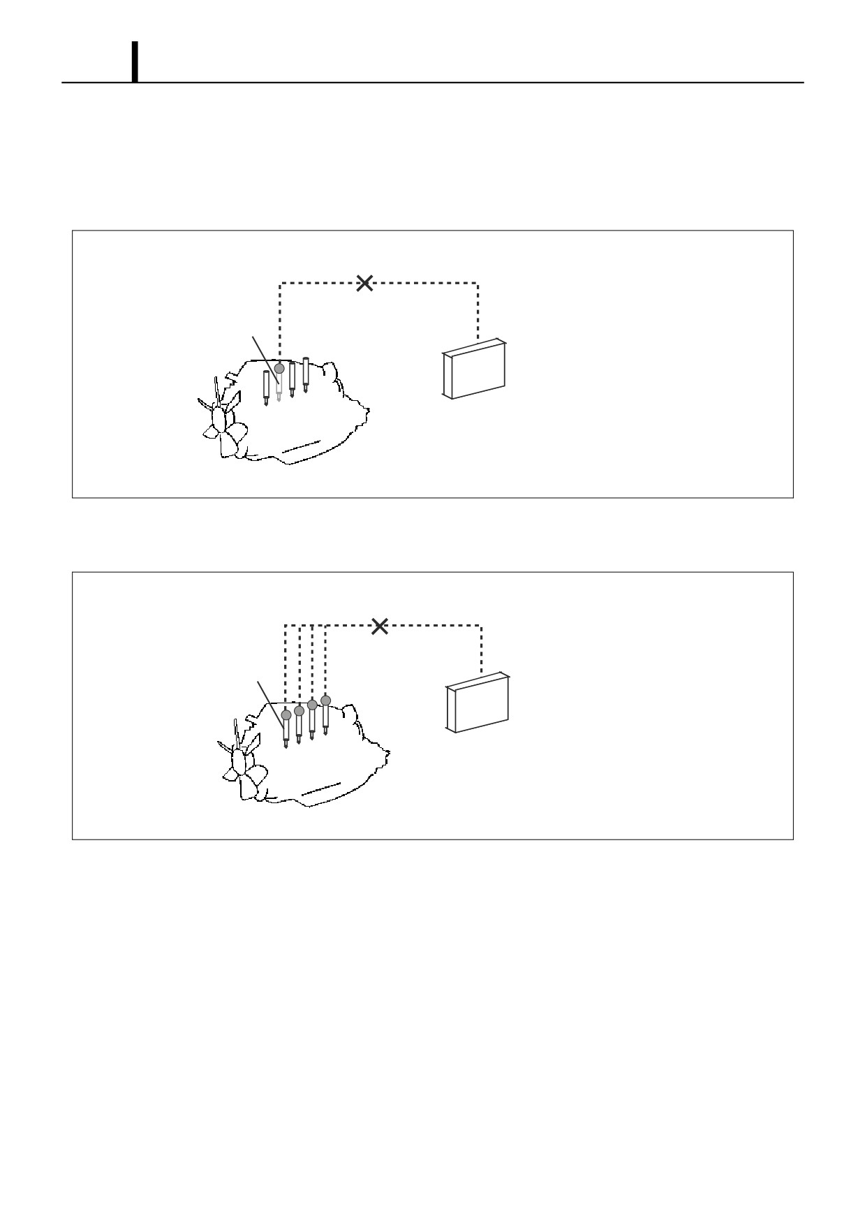
Handling Injectors with QR Codes (Reference)
- Injectors with QR codes have the engine ECU recognize and correct the injectors, so when an injector or the engine
ECU is replaced, it is necessary to register the injector's ID code in the engine ECU.
Replacing the Injector
- It is necessary to register the ID code of the injector that has been replaced in the engine ECU.
"No correction resistance, so no electrical recognition capability."
Spare Injector
Engine ECU
* Necessary to record the injector ID codes in the Engine ECU.
QD1536E
Replacing the Engine ECU
- It is necessary to register the ID codes of all the vehicle injectors in the engine ECU.
"No correction resistance, so no electrical recognition capability."
Vehicle-Side Injector
Spare Engine ECU
* Necessary to record the injector ID codes in the Engine ECU.
Q000985E
Operation Section
1-59
6. DESCRIPTION OF CONTROL SYSTEM COMPONENTS
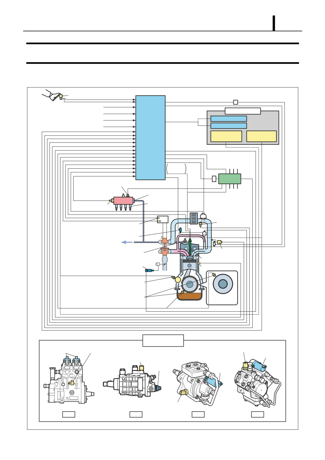
6.1 Engine Control System Diagram (Reference)
Accelerator Position Sensor
Ignition Switch Signal
Supply Pump
Starter Signal
PCV(HP0)
Warm-Up Switch Signal
Vehicle Speed Signal
SCV(HP2·3·4)
TDC(G) Sensor
Fuel Temperature
Engine ECU
(HP0)
Sensor (HP2·3·4)
Charge
Circuit
EDU
Pressure Discharge Valve
Pressure Limiter
Rail
Flow Damper
Rail Pressure Sensor
(Large Vehicles)
Intake Air
Temperature
Airflow Meter
Sensor
(with Intake Air Temperature Sensor)
E-VRV for EGR
To Fuel Tank
Intake Air
Fuel Temperature Sensor (HP0)
Pressure Sensor
Injector
EGR Shut-Off VSV
Coolant Temperature Sensor
Cylinder Recognition Sensor
(TDC (G) Sensor: HP2, 3, 4)
Crankshaft Position Sensor
Flywheel
(Engine Speed Sensor)
Supply Pump
TDC (G) Sensor
Fuel Temperature Sensor
PCV
SCV
Fuel Temperature Sensor
SCV
SCV
Fuel Temperature Sensor
HP0
HP2
HP3
HP4
Q000874E
Operation Section
1-60
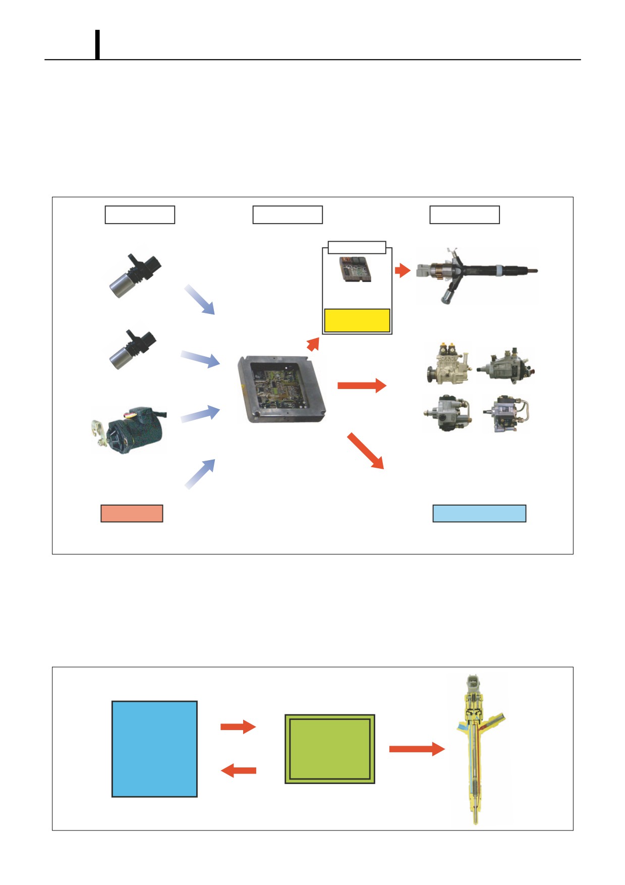
6.2 Engine ECU (Electronic Control Unit)
z The engine ECU constantly ascertains the status of the engine through signals from the sensors, calculates fuel injec-
tion quantities etc. appropriate to the conditions, actuates the actuators, and controls to keep the engine in an optimal
state. The injectors are actuated by either the EDU or the charge circuit in the engine ECU. This actuation circuit de-
pends on the specifications of the model it is mounted in. The ECU also has a diagnosis function for recording system
troubles.
Sensors
Engine ECU
Actuators
Actuation Circuit
EDU
or
Cylinder Recognition Sensor
Injector
Charge Circuit
(TDC (G) Sensor)
(Built into ECU)
Crankshaft Position Sensor
(Engine Speed Sensor)
Engine ECU
Supply Pump
(PCV : HP0, SCV : HP2 · HP3 · HP4)
Accelerator Position Sensor
Other Sensors
Other Actuators
Q000875E
6.3 EDU (Electronic Driving Unit)
(1) General Description
• An EDU is provided to enable high-speed actuation of the injectors. The EDU has a high-voltage generation device
(DC/DC converter) and supplies high voltage to the injectors to actuate the injectors at high speed.
Actuation Signal
Actuation Output
ECU
EDU
Check Signal
Q000876E
Operation Section
1-61
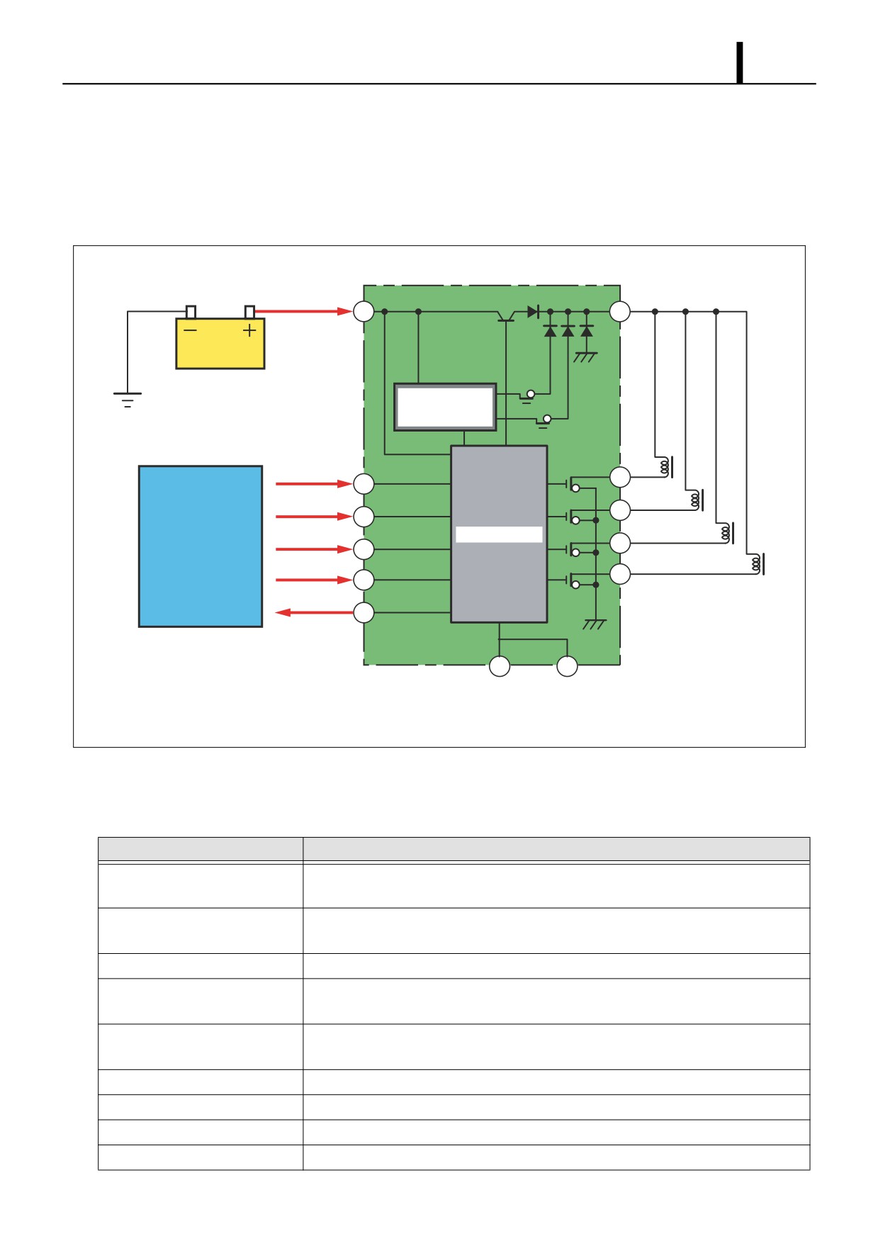
(2) Operation
• The high-voltage generating device in the EDU converts the battery voltage into high voltage. The ECU sends signals
to terminals B through E of the EDU in accordance with the signals from the sensors. Upon receiving these signals,
the EDU outputs signals to the injectors from terminals H through K. At this time, terminal F outputs the IJf injection
verification signal to the ECU.
+B
COM
A
L
High Voltage
Generation Circuit
IJt#1
H
B
IJt#1
IJt#2
I
C
IJt#2
Control Circuit
IJt#3
J
ECU
D
IJt#3
IJt#4
K
E
IJt#4
IJf
F
G
M
GND
GND
Q000877E
6.4 Various Sensors
Various Sensor Functions
Sensor
Functions
Crankshaft Position Sensor
Detects the crankshaft angle and outputs the engine speed signal.
(Engine Speed Sensor)
Cylinder Recognition Sensor
Identifies the cylinders.
(TDC (G) Sensor)
Accelerator Position Sensor
Detects the opening angle of the accelerator pedal.
Intake Air Temperature Sensor
Detects the temperature of the intake air after it has passed through the turbo-
charger.
Mass Airflow Meter
Detects the flow rate of the intake air. It also contains an intake air temperature sen-
sor that detects the temperature of the intake air (atmospheric temperature).
Coolant Temperature Sensor
Detects the engine coolant temperature.
Fuel Temperature Sensor
Detects the fuel temperature.
Intake Air Pressure Sensor
Detects the intake air pressure.
Atmospheric Pressure Sensor
Detects the atmospheric pressure.
Operation Section
1-62
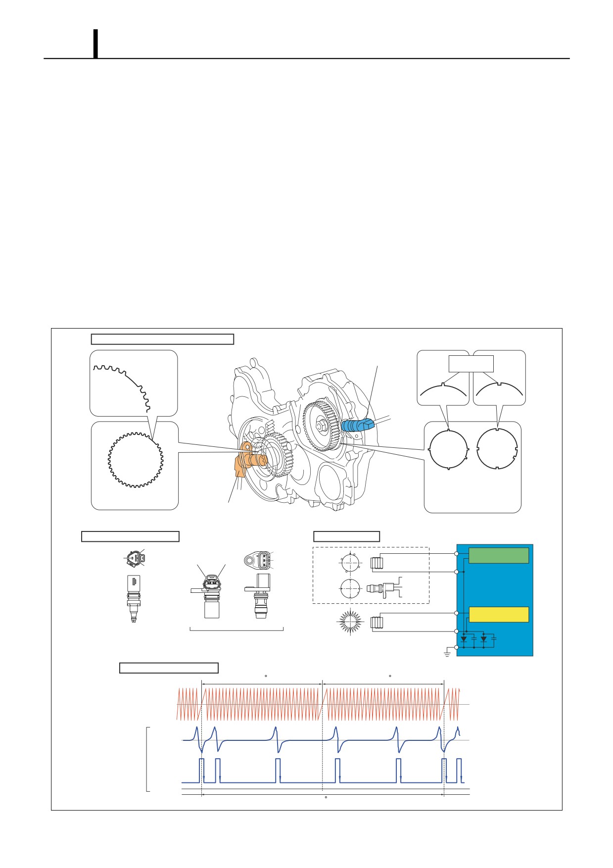
(1) Crankshaft Position Sensor (Engine Speed Sensor) and Cylinder Recognition Sensor
{TDC (G) Sensor}
Crankshaft Position Sensor (Engine Speed Sensor)
• The crankshaft position sensor is installed near the crankshaft timing gear or the flywheel. The sensor unit is a MPU
(magnetic pickup) type. When the engine speed pulsar gear installed on the crankshaft passes the sensor section,
the magnetic field of the coil within the sensor changes, generating AC voltage. This AC voltage is detected by the
engine ECU as the detection signal. The number of pulses for the engine speed pulsar depends on the specifications
of the vehicle the sensor is mounted in.
Cylinder Recognition Sensor {TDC (G) Sensor}
• The cylinder recognition sensor is installed on the supply pump unit for the HP0 system, but for the HP2, HP3, or HP4
system, it is installed near the supply pump timing gear. Sensor unit construction consists of the MPU type, which is
the same as for the crankshaft position sensor, and the MRE (magnetic resistance element) type. For the MRE type,
when the pulsar passes the sensor, the magnetic resistance changes and the voltage passing through the sensor
changes. This change in voltage is amplified by the internal IC circuit and output to the engine ECU. The number of
pulses for the TDC pulsar depends on the specifications of the vehicle the sensor is mounted in.
Sensor Mounting Position (Reference)
Cylinder Recognition Sensor
Pulsar
(TDC (G) Sensor)
(Gearless Section)
Pulsar
For MPU
For MRE
Type
Type
Engine Speed Pulsar
TDC (G) Pulsar
Crankshaft Position Sensor
(Engine Speed Sensor)
External View of Sensor
Circuit Diagram
ECU
NE-
VCC
Shielded
MPU
TDC(G)
TDC (G) Input Circuit
TDC(G)- TDC(G)
GND
Wire
NE+
Type
TDC(G)
VCC
MRE
TDC(G)
Type
GND
Engine Speed
NE
Input Circuit
MPU Type MRE Type
Crankshaft Position Sensor
Cylinder Recognition Sensor
(Engine Speed Sensor)
(TDC (G) Sensor)
Pulse Chart (Reference)
360 CA
360 CA
Engine Speed
Pulse
MPU
Type
TDC (G)
Pulse
MRE
Type
0V
720 CA
Q000878E
Operation Section
1-63
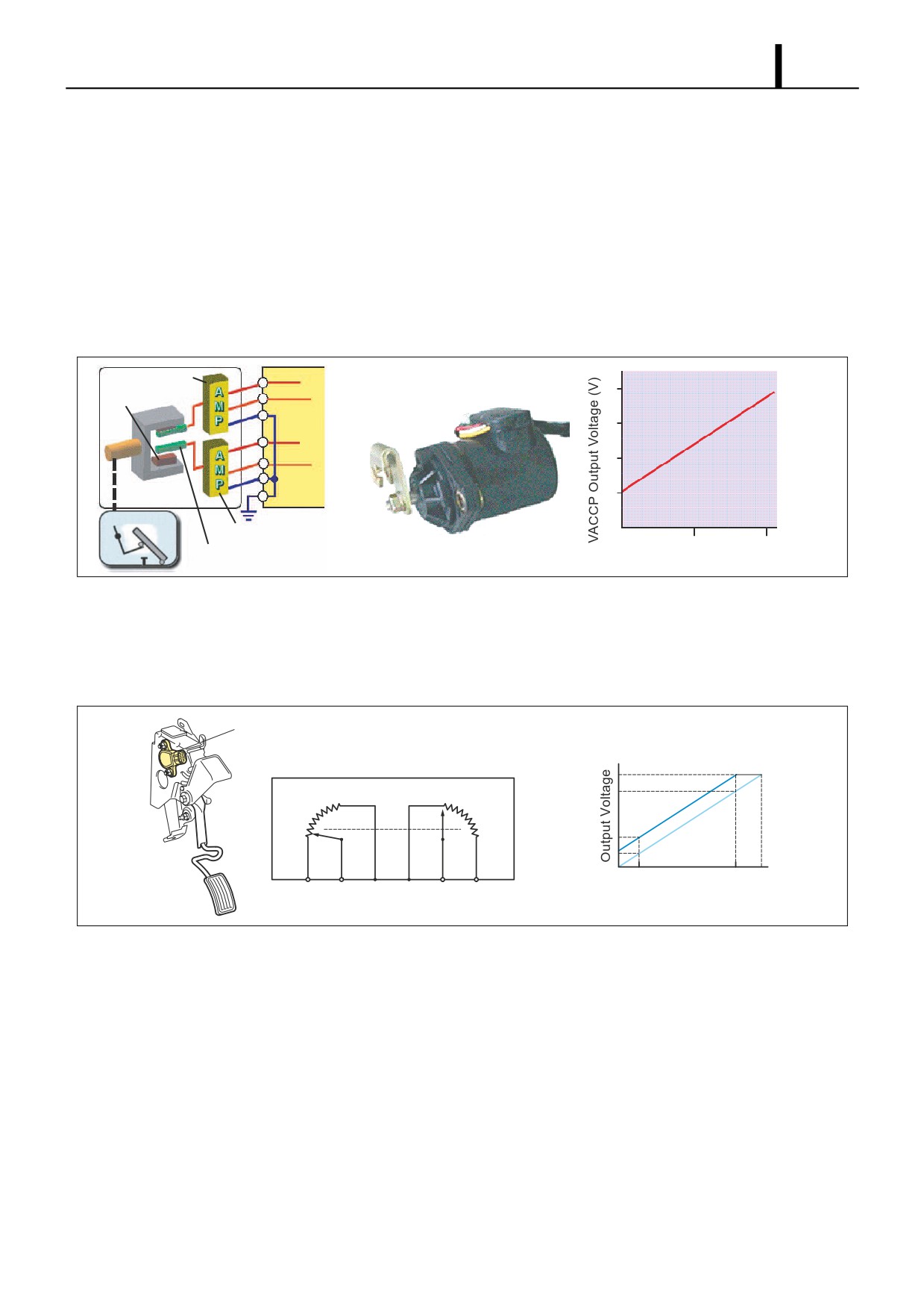
(2) Accelerator Position Sensor
• The accelerator position sensor converts the accelerator opening into an electric signal and outputs it to the engine
ECU. There are two types of accelerator position sensor: the hall element type and the contact type. In addition, to
provide backup in the event of breakdown, there are two systems and the output voltage is offset.
Hall Element Type
- This sensor uses a hall element to generate voltage from change in the direction of the magnetic field. A magnet
is installed on the shaft that rotates linked with the accelerator pedal, and the rotation of this shaft changes the mag-
netic field of the Hall element. The voltage generated by this change in the magnetic field is amplified by an amplifier
and input to the engine ECU.
Amplifier No. 1
A-VCC
+5V
VACCP1
4
Magnets (Pair)
A-GND
3
A-VCC
+5V
VACCP2
2
A-GND
1
ECU
Accelerator Pedal
Amplifier No. 2
0
50
100
Hall Elements (2)
Q000879E
Accelerator Opening (%)
Contact Type
- The sensor uses a contact-type variable resistor. Since the lever moves linked with the accelerator pedal, the sen-
sor resistance value varies with the accelerator pedal opening. Therefore, the voltage passing the sensor changes,
and this voltage is input to the engine ECU as the accelerator opening signal.
Accelerator Position Sensor
Accelerator Position Sensor
Output Voltage Characteristic
Accelerator Position Sensor Circuit Diagram
Fully Open
Fully Closed
VPA2
Fully
Fully
VPA1
Closed
Open
Fully Closed Fully Open
EP2 VPA2 VCP2 EP1 VPA1 VCP1
Accelerator Pedal Position
Q000880E
Operation Section
1-64
(3) Intake Air Temperature Sensor
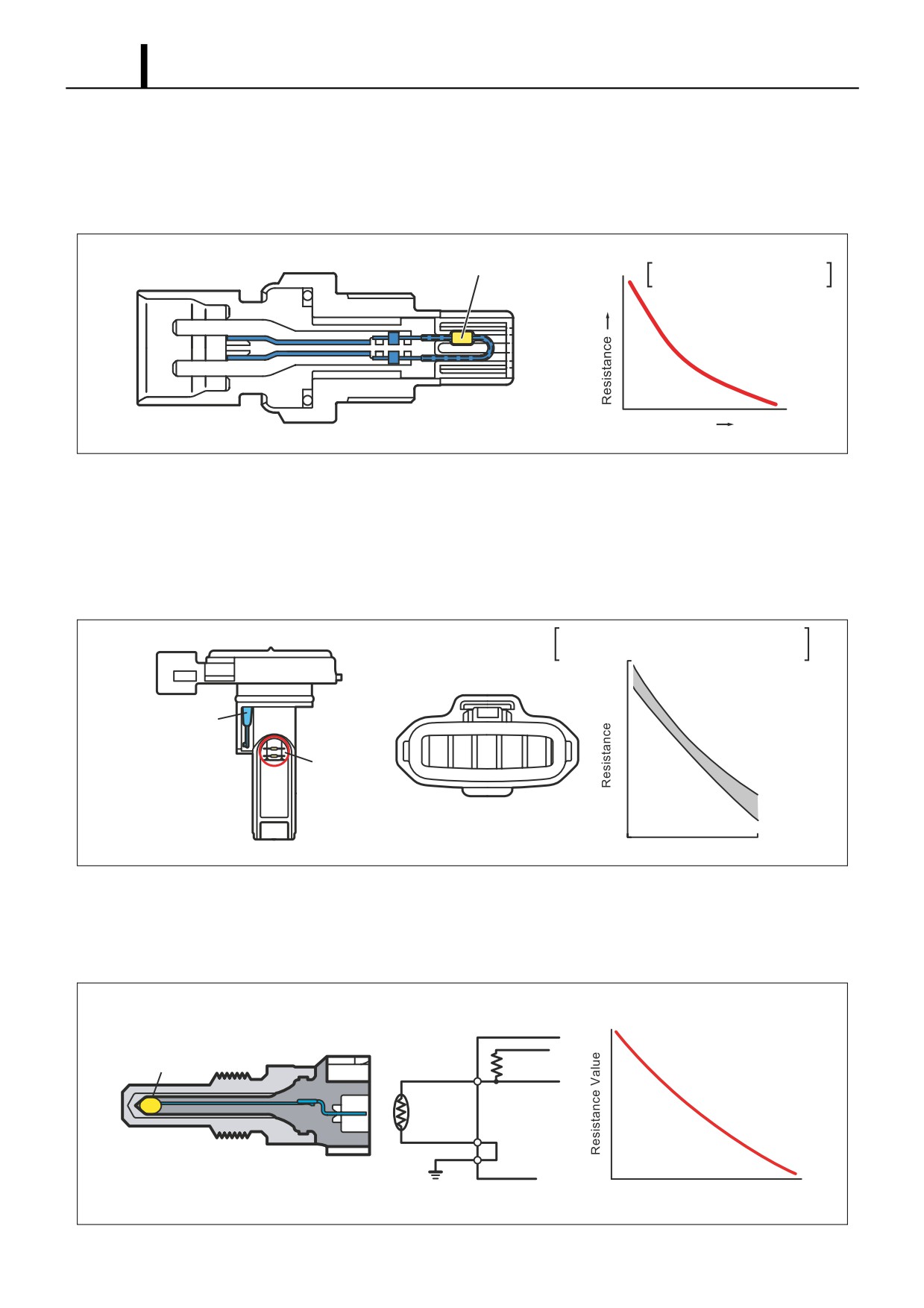
• The intake air temperature sensor detects the temperature of the intake air after it has passed the turbocharger. The
sensor portion that detects the temperature contains a thermistor. The thermistor, which has an electrical resistance
that changes with temperature, is used to detect the intake air temperature.
Thermistor
Temperature
Resistance -
Characteristic
Temperature
Q000881E
(4) Mass Airflow Meter (with Built-In Intake Air Temperature Sensor)
• The mass air flow meter is installed behind the air cleaner and detects the intake air flow (mass flow). This sensor is
a hot-wire type. Since the electrical resistance of the hot wire varies with the temperature, this characteristic is utilized
to measure the intake air quantity. The mass airflow meter also has a built-in intake air temperature sensor (thermistor
type) and detects the intake air temperature (atmospheric temperature).
Intake Air Temperature
Temperature
-
Sensor Resistance
Characteristic
Intake Air
Temperature
Sensor
+B
E2G
VG
THAF
E2
Hot Wire
Temperature C ( F)
Q000882E
(5) Coolant Temperature Sensor
• The coolant temperature sensor is installed on the cylinder block and detects the coolant temperature. This sensor is
a thermistor type.
Coolant Temperature
Water Temperature
-
Sensor Resistance
Characteristic
ECU
+5V
Thermistor
VTHW
A-GND
Coolant Temperature
Q000883E

Operation Section
1-65
(6) Fuel Temperature Sensor
• This is a thermistor type sensor that detects the fuel temperature. In the HP2, HP3, and HP4 systems, this sensor is
installed on the supply pump unit, but in the HP0 system, it is installed on a leak pipe from an injector.
Resistance - Temperature
Thermistor
Characteristic
Temperature
Q000848E
(7) Intake Air Temperature Sensor and Atmospheric Pressure Sensor
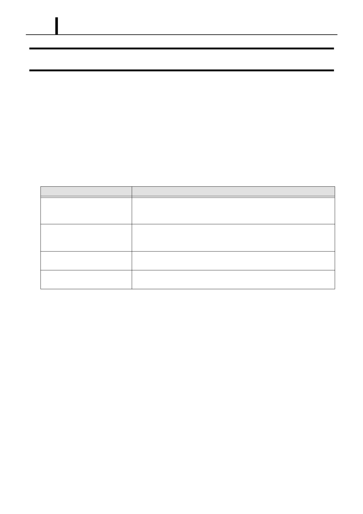
• This sensor is a semiconductor type sensor. It measures pressure utilizing the piezoelectric effect that when the pres-
sure on the silicon element in the sensor changes, its electrical resistance changes. In addition, the air pressure on
this sensor is switched between the pressure within the intake manifold and the atmospheric pressure, so both the
intake air pressure and the atmospheric pressure are detected with one sensor. The switching between intake air
pressure and atmospheric pressure is handled by the VSV (vacuum switching valve). When any one of the conditions
below is established, the VSV is switched ON for 150 msec. by command of the engine ECU to detect the atmospheric
pressure. When none of the conditions below is established, the VSV is switched OFF to detect the intake air pres-
sure.
Atmospheric Pressure Measurement Conditions
- Engine speed = 0 rpm
- Starter ON
- Stable idling state
Pressure
PIM Output Voltage -
Characteristic
VC PIM E2
Absolute Pressure
Q000885E
Operation Section
1-66
7. CONTROL SYSTEM
7.1 Fuel Injection Control
(1) General Description
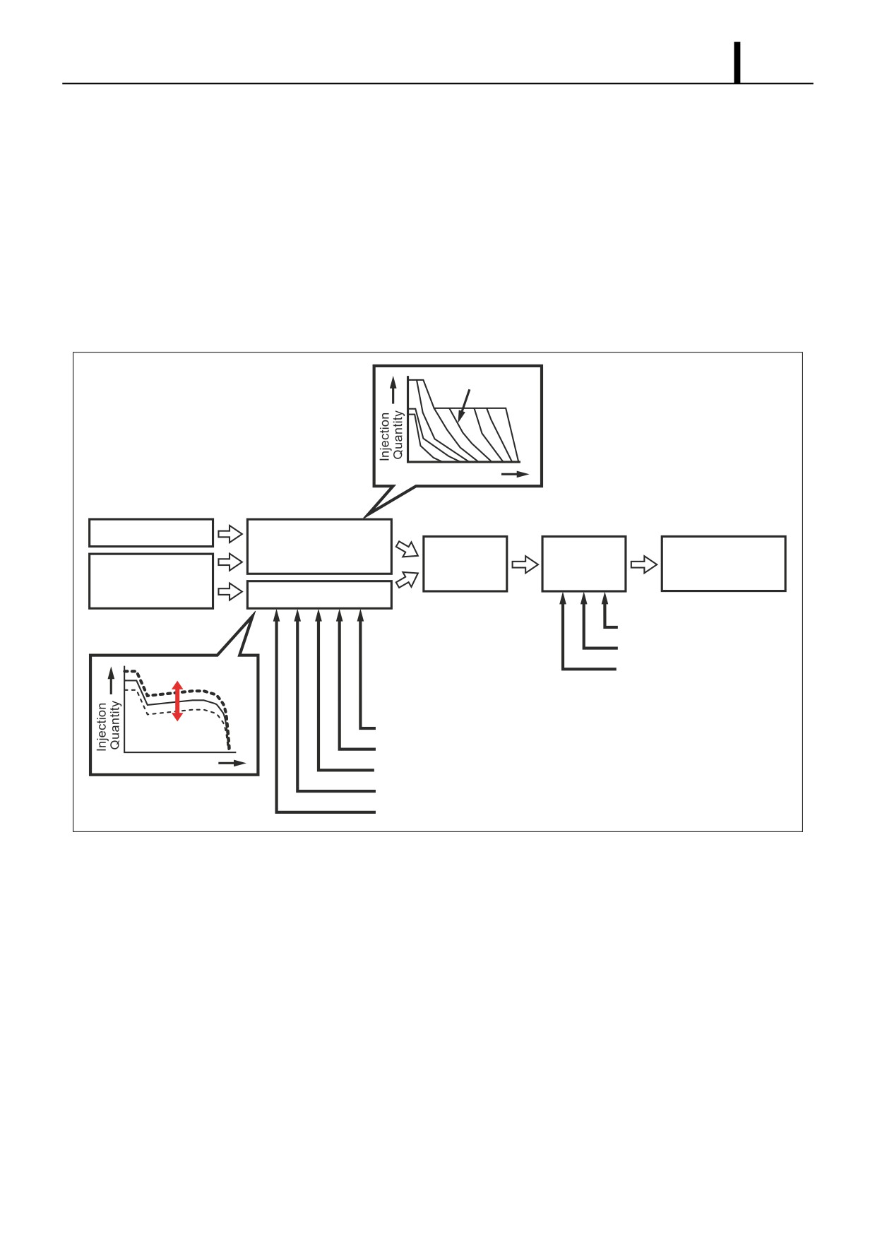
• This system effects more appropriate control of the fuel injection quantity and injection timing than the mechanical
governor or timer used in the conventional injection pump. The engine ECU performs the necessary calculations
based on the signals that are received from the sensors located on the engine and the vehicle. Then, the ECU controls
the timing and duration of the current that is applied to the injectors in order to obtain optimal injection timing and
injection quantity.
(2) Various Types of Fuel Injection Controls
Control
Functions
Fuel Injection Quantity Control
This control replaces the function of the governor in the conventional injection
pump. It achieves optimal injection quantity by effecting control in accordance with
the engine speed and accelerator opening signals.
Fuel Injection Timing Control
This control replaces the function of the timer in the conventional injection pump. It
achieves optimal injection timing by effecting control in accordance with the
engine speed and the injection quantity.
Fuel Injection Rate Control
This function controls the ratio of the fuel quantity that is injected from the orifice of
(Pilot Injection Control)
the injector within a given unit of time.
Fuel Injection Pressure Control
This control uses the rail pressure sensor to measure the fuel pressure, and it
feeds this data to the engine ECU in order to control the pump discharge quantity.
Operation Section
1-67
(3) Fuel Injection Quantity Control
General Description
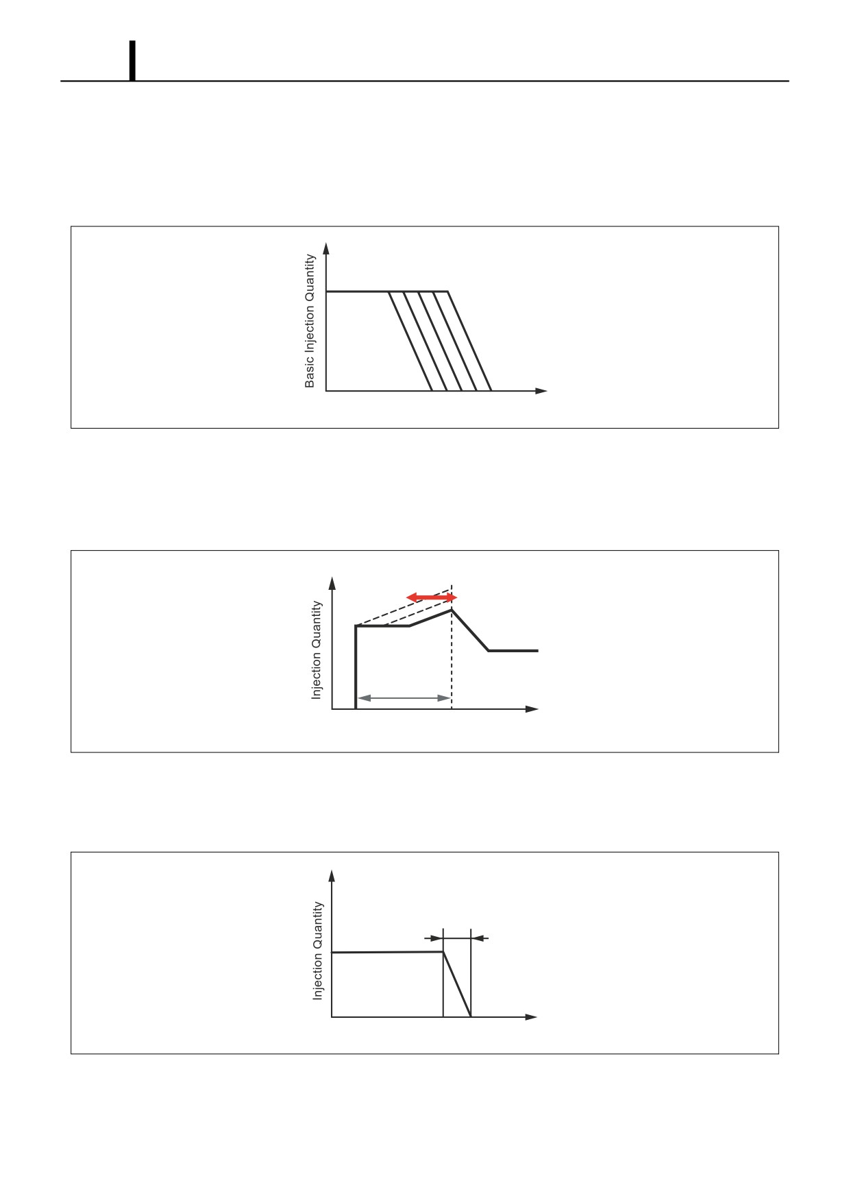
• This control determines the fuel injection quantity by adding coolant temperature, fuel temperature, intake air temper-
ature, and intake air pressure corrections to the basic injection quantity. The engine ECU calculates the basic injection
quantity based on the engine operating conditions and driving conditions.
Injection Quantity Calculation Method
• The calculation consists of a comparison of the following two values: 1. The basic injection quantity that is obtained
from the governor pattern, which is calculated from the accelerator position and the engine speed. 2. The injection
quantity obtained by adding various types of corrections to the maximum injection quantity obtained from the engine
speed. The lesser of the two injection quantities is used as the basis for the final injection quantity.
Accelerator Opening
Engine Speed
Accelerator Opening
Basic Injection Quantity
Low
Corrected
Injector Actuation
Quantity
Final Injection
Period Calculation
Side Selected
Quantity
Engine Speed
Maximum Injection Quantity
Individual Cylinder
Correction Quantity
Speed Correction
Injection Pressure Correction
Intake Air Pressure Correction
Intake Air Temperature Correction
Engine Speed
Atmospheric Pressure Correction
Ambient Temperature Correction
Cold Engine Maximum Injection Quantity Correction
Q000887E
Operation Section
1-68
Set Injection Quantities
• Basic Injection Quantity
This quantity is determined by the engine speed and the accelerator opening. With the engine speed constant, if the
accelerator opening increases, the injection quantity increases; with the accelerator opening constant, if the engine
speed rises, the injection quantity decreases.
Accelerator Opening
Engine Speed
Q000888E
• Starting Injection Quantity
This is determined based on the basic injection quantity for when the engine starts up and the added corrections for
the starter S/W ON time, the engine speed, and the coolant temperature. If the coolant temperature is low, the injec-
tion quantity is increased. When the engine has completely started up, this mode is cancelled.
Coolant Temperature
High
Low
Starting
Base Injection
Quantity
STA ON Time
STA ON
Starting
Q000889E
• Injection Quantity for Maximum Speed Setting
Determined by the engine speed. The injection quantity is restricted to prevent an excessive rise in engine speed
(overrun).
Injection Quantity
for Maximum Speed Setting
Engine Speed
Q000890E
Operation Section
1-69
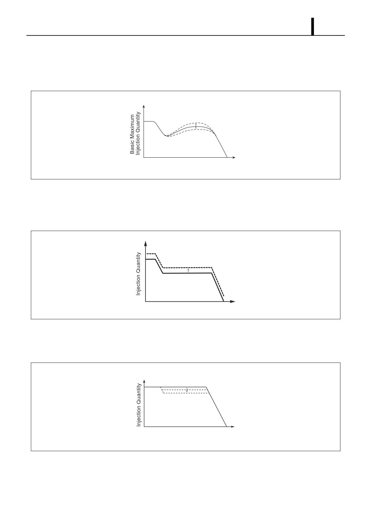
• Maximum Injection Quantity
This is determined based on the basic maximum injection quantity determined by the engine speed, and the added
corrections for coolant temperature, fuel temperature, intake air temperature, atmospheric temperature, intake air
pressure, atmospheric pressure, and full Q adjustment resistance (only for the 1st generation HP0 system), etc.
Engine Speed
QB0717E
Corrections
• Cold Engine Maximum Injection Quantity Correction
When the coolant temperature is low, whether during start-up or during normal operation, this correction increases
the injection quantity.
Engine Speed
Q000891E
• Intake Air Pressure Correction
When the intake air pressure is low, the maximum injection quantity is restricted in order to reduce the emission of
black smoke.
Intake Air Pressure
Correction Quantity
Engine Speed
Q000892E
Operation Section
1-70
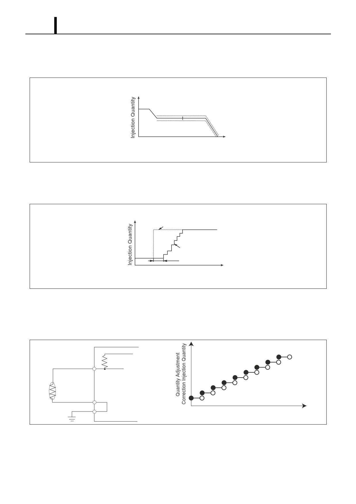
• Atmospheric Pressure Correction
The maximum injection quantity is increased and decreased according to the atmospheric pressure. When the atmo-
spheric pressure is high, the maximum injection quantity is increased.
Atmospheric Pressure
Correction Quantity
Engine Speed
Q000893E
• Injection Quantity Delay Correction for Acceleration
During acceleration, if there is a large change in the accelerator pedal opening, the injection quantity increase is de-
layed in order to prevent black smoke emissions.
Change in Accelerator
Pedal Position
Injection Quantity
After Correction
Delay
Time
Q000487E
• Full Q Adjustment Resistance (Only for 1st Generation HP0 Systems)
The full Q resistance is for correcting the injection quantity for a full load. The maximum injection quantity is increased
or decreased by the car manufacturer to match to standards. There are 15 types of full Q adjustment resistance. The
appropriate one is selected and used.
ECU
+5V
VLQC
A-GND
Quantity Adjustment
Resistor Correction Voltage
Operation Section
1-71
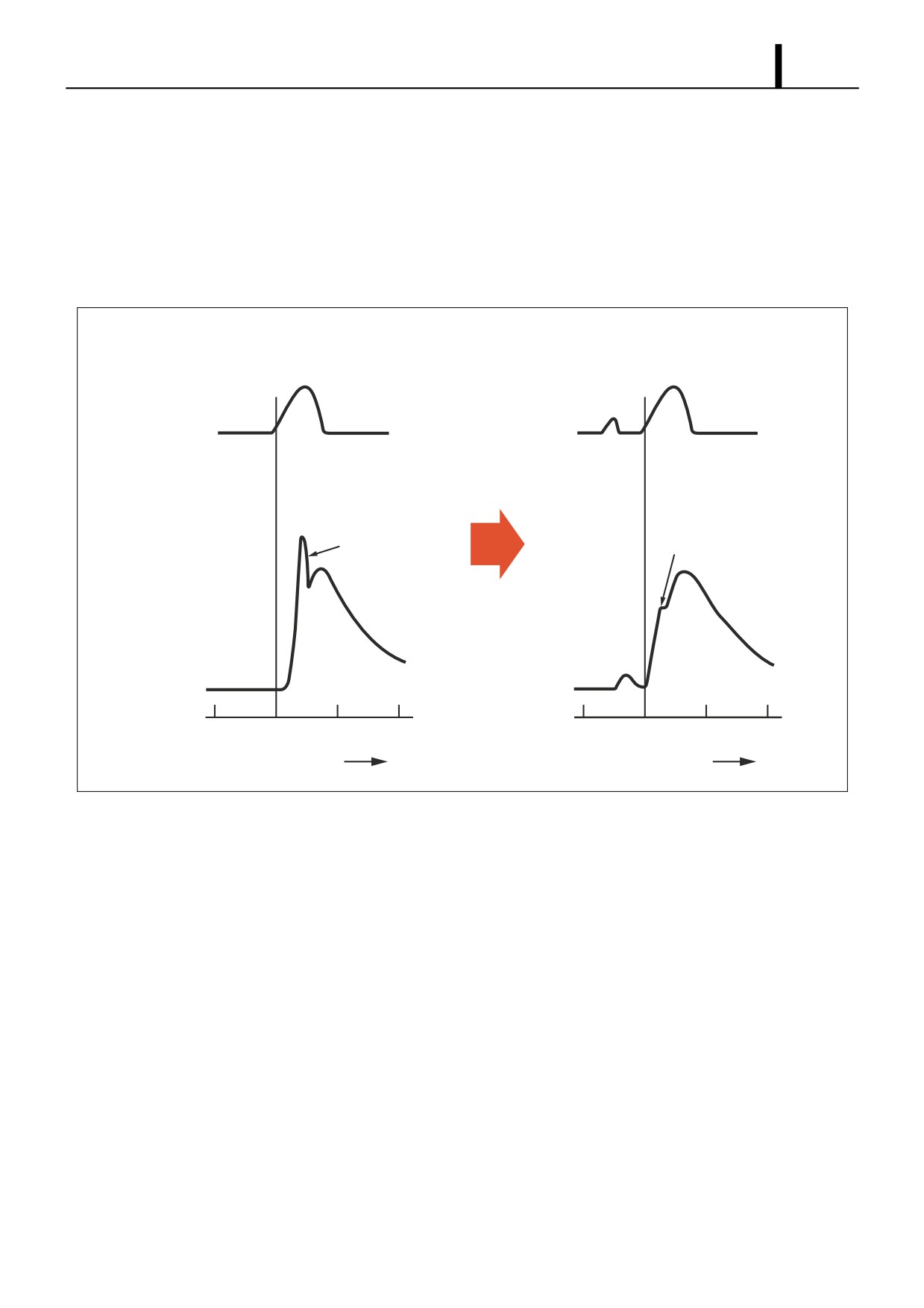
(4) Fuel Injection Rate Control
• Although the injection rate increases with the adoption of high-pressure fuel injection, the ignition lag, which is the
delay from the start of injection to the beginning of combustion, cannot be shortened to less than a certain period of
time. Therefore, the quantity of fuel injected until ignition takes place increases (the initial injection rate is too high),
resulting in explosive combustion simultaneous with ignition, and an increase in NOx and sound. To counteract this
situation, pilot injection is provided to keep the initial injection at the minimum requirement rate, to dampen the primary
explosive combustion, and to reduce NOx and noise.
[Ordinary Injection]
[Pilot Injection]
Injection Rate
Small First-Stage
Large First-Stage
Combustion
Combustion
Heat Release Rate
-20
TDC
20
40
-20
TDC
20
40
Crankshaft Angle (deg)
Crankshaft Angle (deg)
Q000895E
Operation Section
1-72
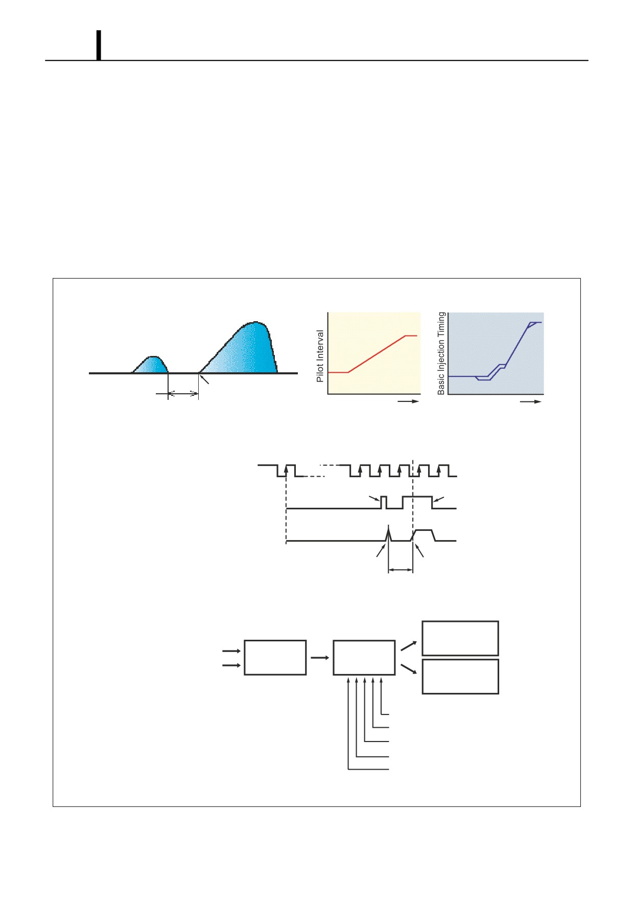
(5) Fuel Injection Timing Control
• The fuel injection timing is controlled by the timing of the current applied to the injectors. After the main injection period
is decided, the pilot injection and other injection timing is determined.
Main Injection Timing
- The basic injection timing is calculated from the engine speed (engine speed pulse) and the final injection quantity,
to which various types of corrections are added in order to determine the optimal main injection timing.
Pilot Injection Timing (Pilot Interval)
- Pilot injection timing is controlled by adding a pilot interval value to the main injection. The pilot interval is calculated
based on the final injection quantity, engine speed, coolant temperature, atmospheric temperature, and atmospher-
ic pressure (map correction). The pilot interval at the time the engine is started is calculated from the coolant tem-
perature and engine speed.
Basic Injection
Pilot Interval
Timing
Engine Speed
Engine Speed
1. Outline of Injection Timing Control Timing
Actual Top Dead Center
0
1
Engine Speed
NE
Pulse
Pilot Injection
Main Injection
Injector Solenoid Valve
INJ
Control Pulse
Nozzle Needle
lift
Lift
Pilot Injection Timing
Main Injection Timing
Pilot Interval
2. Injection Timing Calculation Method
Main
Injection Timing
Engine Speed
Basic Injection
Correction
Injection Quantity
Timing
Pilot
Injection Timing
Battery Voltage Correction
Intake Air Pressure Correction
Intake Air Temperature Correction
Atmospheric Pressure Correction
Coolant Temperature Correction
Q000896E
Operation Section
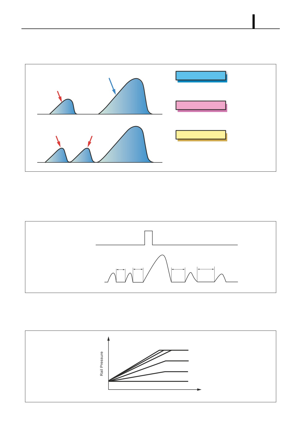
1-73
Split Injection
- The purpose of split injection is to improve the startability of a cold engine. Before the conventional main injection
takes place, this function injects two or more extremely small injections of fuel.
Main Injection
Main Injection
Pilot Injection
This is the same as
conventional
fuel injection.
Pilot Injection
Before the main injection, a small
quantity of fuel is injected.
Pilot Injection
Pre-Injection
Multi-Injection
If the temperature is low when the engine
starts, a small quantity of fuel is injected
divided over multiple injections before the
main injection.
Q000897E
Multi-Injection Control (Only for Some Models)
- Multi-injection control is when small injections (up to four times) are carried out before and after the main injection
in accordance with the state of the main injection and engine operation. This interval (the time A-D in the diagram
below) is based on the final injection quantity, engine speed, coolant temperature, and atmospheric pressure (map
correction). The interval during start-up is based on the coolant temperature and engine speed.
TDC
TDC (G) Pulse
A
B
C
D
Injection Rate
Q000898E
(6) Fuel Injection Pressure Control
• The engine ECU calculates the fuel injection pressure, which is determined by the final injection quantity and the en-
gine speed. The calculation is based on the coolant temperature and engine speed during start-up.
Final Injection Quantity
Engine Speed
Q000899E
Operation Section
1-74
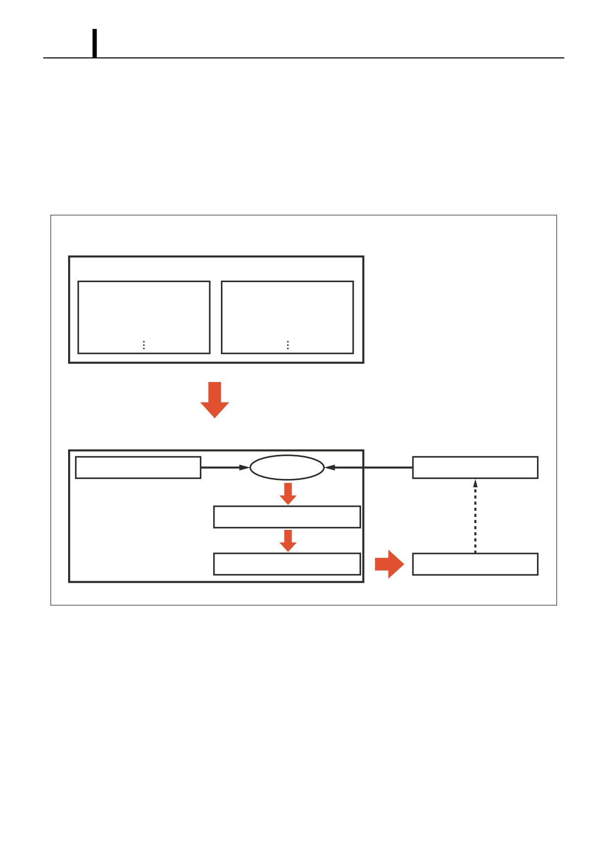
(7) Other Injection Quantity Control
Idle Speed Control (ISC) System
• The idle speed control system controls the idle speed by regulating the injection quantity in order to match the actual
speed to the target speed calculated by the computer. The ISC can be automatic ISC or manual ISC.
Automatic ISC
- With automatic ISC, the engine ECU sets the target speed. The target engine speed varies with the type of trans-
mission (automatic or manual), whether the air conditioner is ON or OFF, the shift position, and the coolant temper-
ature.
Idle Speed Control Conditions
Conditions When Control Starts
Conditions Affecting Control
· Idle Switch
· Water Temperature
· Accelerator Opening
· Air Conditioning Load
· Vehicle Speed
· Shift Position
Engine ECU
Target Engine Speed Calculation
Comparison
Actual Engine Speed
Fuel injection Quantity Correction
Fuel Injection Quantity Instruction
Actuators
Q000900E
Operation Section
1-75
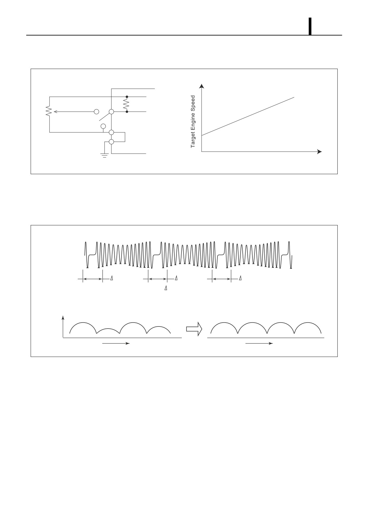
Manual ISC
- The idle engine speed is controlled by the setting on the idle setting button at the driver's seat.
ECU
A-VCC
+5V
V-IMC
A-GND
IMC Volume Terminal Voltage
Q000901E
Idle Vibration Reduction Control
- This control reduces engine vibration during idle. To achieve smooth engine operation, it compares the angle
speeds (times) of the cylinders and regulates injection quantity for each individual cylinder in the event of a large
difference.
#1
#3
#4
t1
t3
t4
(Make the
t for all the cylinders equal.)
Angular Speed
#1
#3
#4
#2
#1
#3
#4
#2
Correction
Crankshaft Angle
Crankshaft Angle
Q000902E