Takeuchi Hydraulic excavator TB1140 (Serial No. 514400002~). Operator's Manual - page 13
6
3. DESCRIPTION OF FUNCTIONS
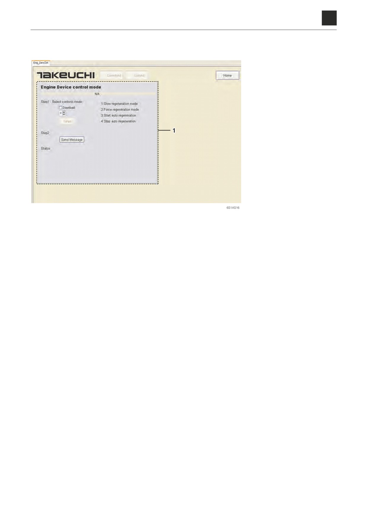
Dev Control mode
1. This function can be used to
forcibly set DPD regenera-
tion settings and activate
manual regeneration.
Operation method
a. In Step 1, select any option from 1 to 4.
“1”: Activate slow regeneration.
“2”: Forcibly activate manual regeneration.
“3”: Set automatic regeneration on.
“4”: Cancel automatic regeneration.
b. Click "Submit" to proceed.
c. In Step 2, click “Send Message” to execute the selection and proceed.
30
3. DESCRIPTION OF FUNCTIONS
6S1AS01
6
3. DESCRIPTION OF FUNCTIONS
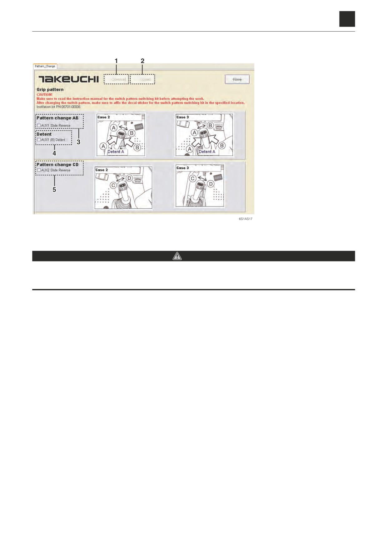
Grip pattern
1. Download: Used to down-
load the settings to the con-
troller.
2. Upload: Used to upload the
current settings from the
controller.
3. Reverse the switch opera-
tion (A) and (B) for the 1st
auxiliary line piping.
4. Set the detent mode target
to switch operation (B).
5. Reverse the switch opera-
tion (C) and (D) for the 2nd/
4th auxiliary line piping.
Changing the switch pattern
DANGER
Make sure to read the instruction manual for the switch pattern switching kit before attempting the work.
After changing the switch pattern, make sure to affix the decal sticker for the switch pattern switching kit in the specified
location.
a. Click on (2) to pull up the current setting conditions.
b. Select the checkboxes for the items to be changed.
c. Click on (1) to download the items set in b. to the controller.
31
3. DESCRIPTION OF FUNCTIONS
6S1AS01
6
3. DESCRIPTION OF FUNCTIONS
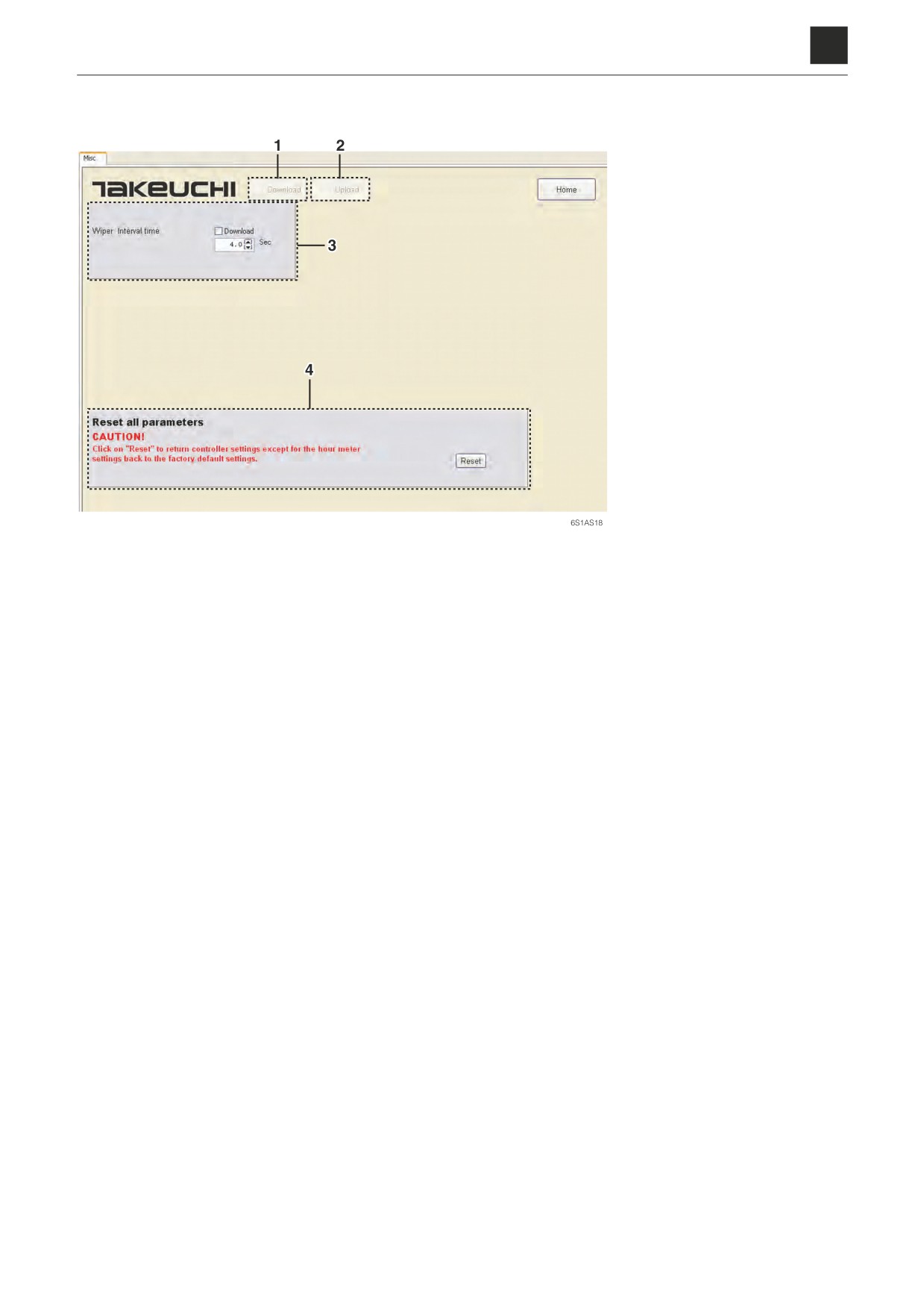
Misc
1. Download: Used to down-
load the settings to the con-
troller.
2. Upload: Used to upload the
current settings from the
controller.
3. Change the wiper interval.
4. Return all settings other than
the hour meter settings back
to their initial values (factory
default settings).
Changing the interval
a. Click on (2) to pull up the current setting conditions.
b. Click above or below (3) to set the option setting to any desired value.
c. Click on (1) to download the value set in b. to the controller.
Initialization
Click on (4) to return controller settings except for the hour meter settings back to the factory default settings.
32
3. DESCRIPTION OF FUNCTIONS
6S1AS01
6
3. DESCRIPTION OF FUNCTIONS
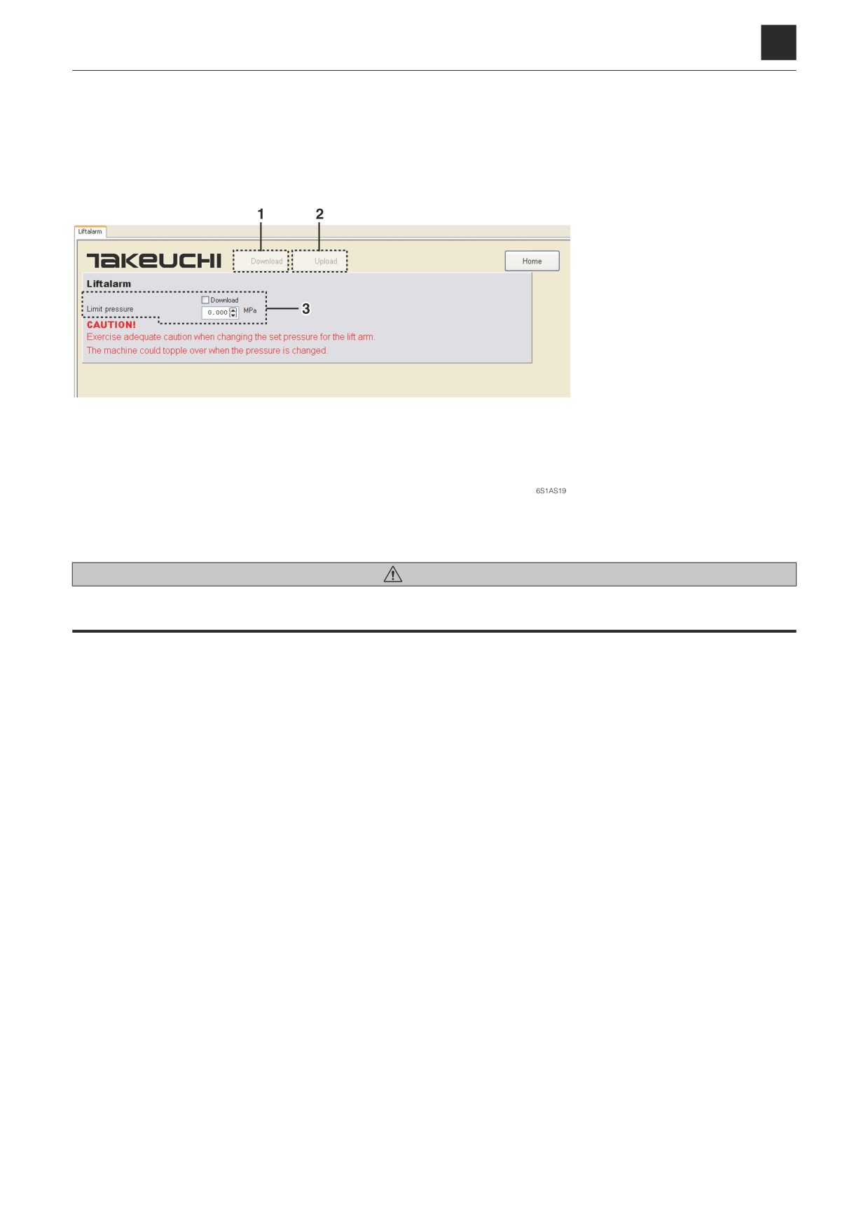
Lift alarm
1. Download: Used to down-
load the settings to the con-
troller.
2. Upload: Used to upload the
current settings from the
controller.
3. Set pressure for the lift alarm
Changing the set pressure for the lift alarm
WARNING
Exercise adequate caution when changing the set pressure for the lift alarm. The machine could topple over when the
pressure is changed.
a. Click on (2) to pull up the current setting conditions.
b. Click above or below (3) to set the option setting to any desired value.
c. Click on (1) to download the value set in b. to the controller.
33
3. DESCRIPTION OF FUNCTIONS
6S1AS01
6
AIR CONDITIONER
AIR CONDITIONER
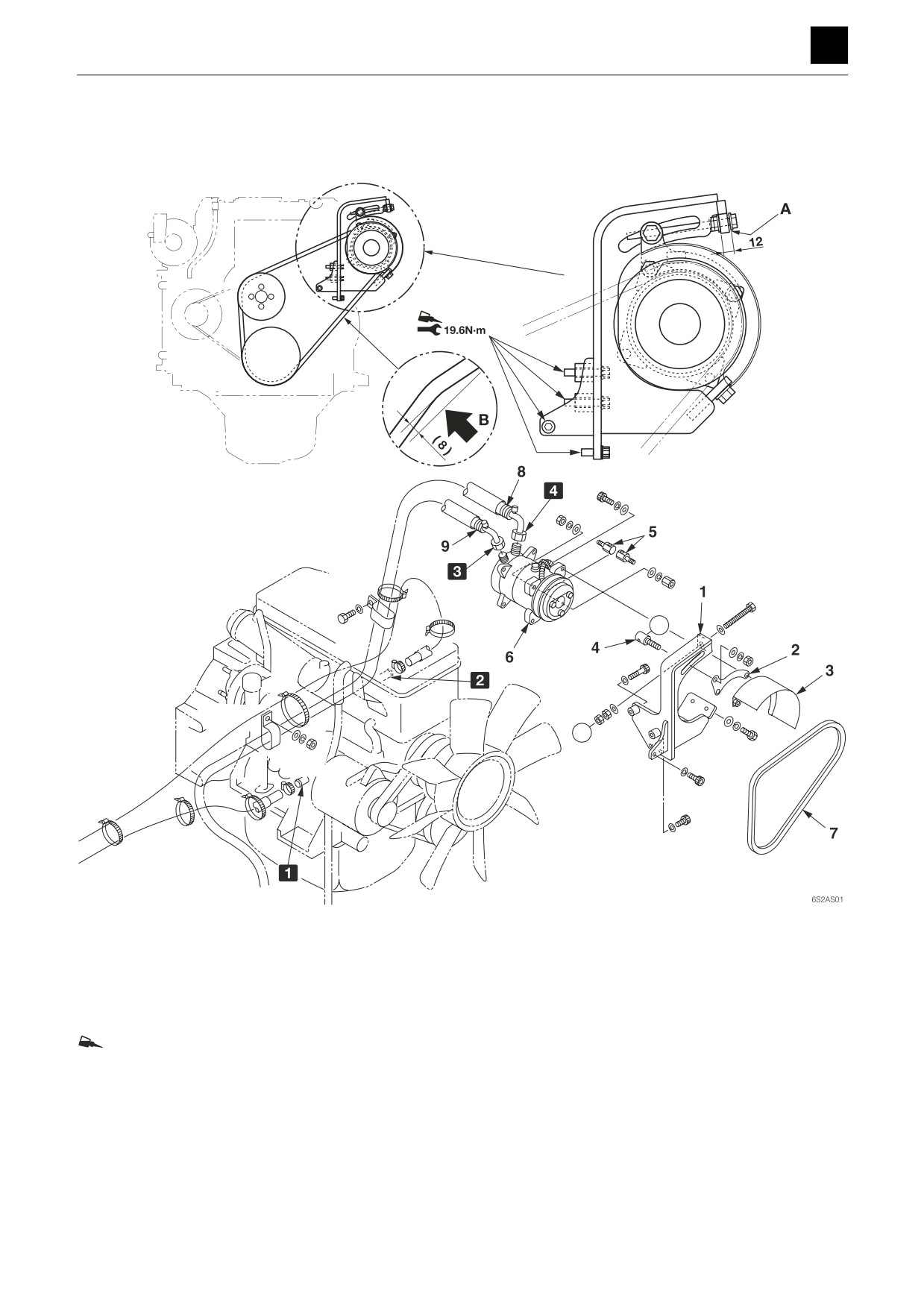
Compressor assembly
X
X
A: Create a clearance.
B: Adjust the fan belt until it yields approximately 8 mm
(0.3 in.) when a force of 98 N (22 lbf) is applied to a
middle point between the pulley and the compressor.
If a tension gauge is used: 529 N (118.9 lbf)
: Loctite #271 or its equivalent
1 Engine IN
1. Bracket
6. Compressor
2 Engine OUT
2. Bracket
7. Belt
3 To “D” condenser IN
3. Guard
8. Hose
4 From “S” air conditioner unit
4. Shaft
9. Hose
5. Shaft
1
AIR CONDITIONER
6S2AS00
6
AIR CONDITIONER
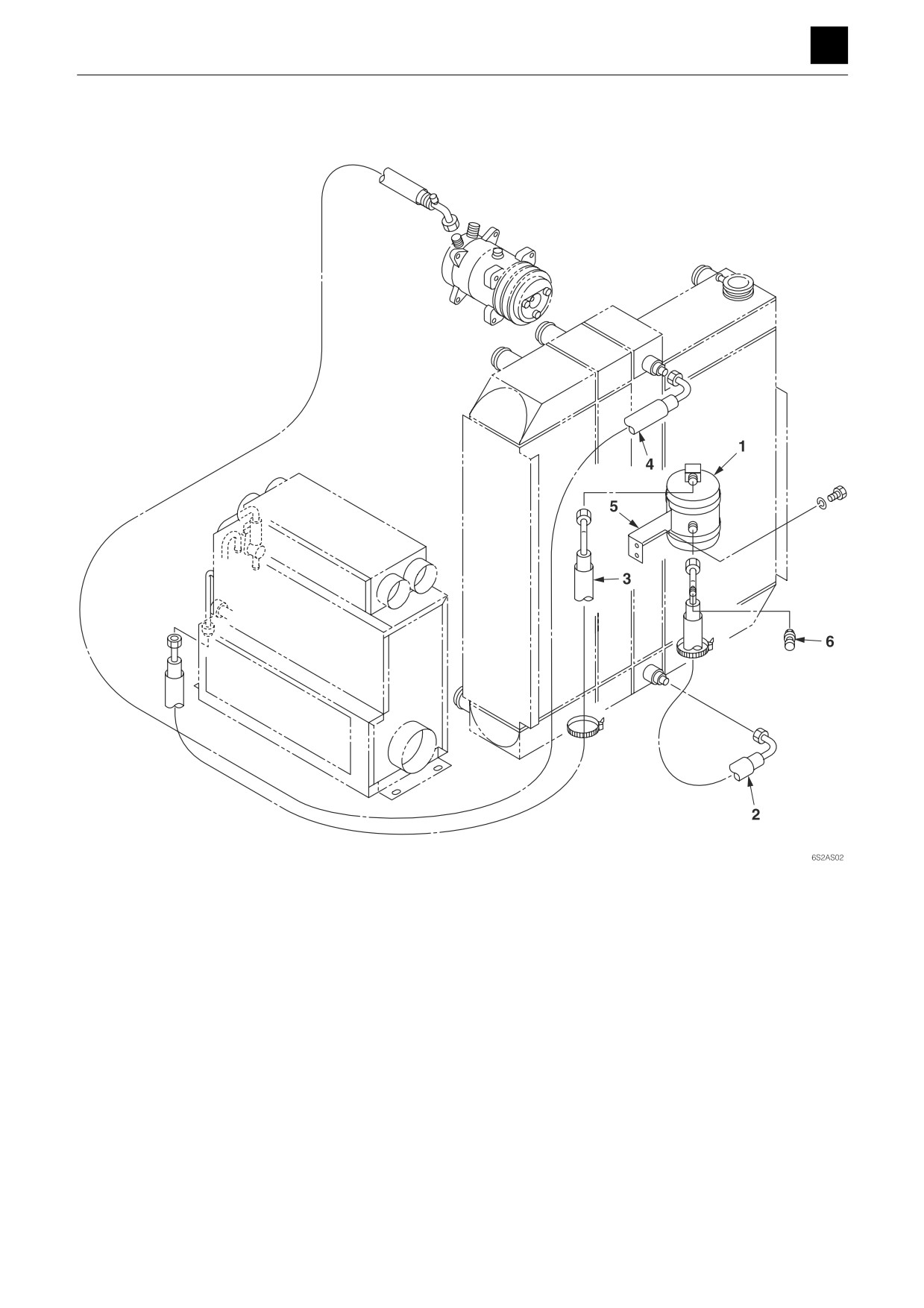
Condenser assembly
1. Dryer
2. Hose
3. Hose
4. Hose
5. Bracket
6. Transducer
2
AIR CONDITIONER
6S2AS00
6
AIR CONDITIONER
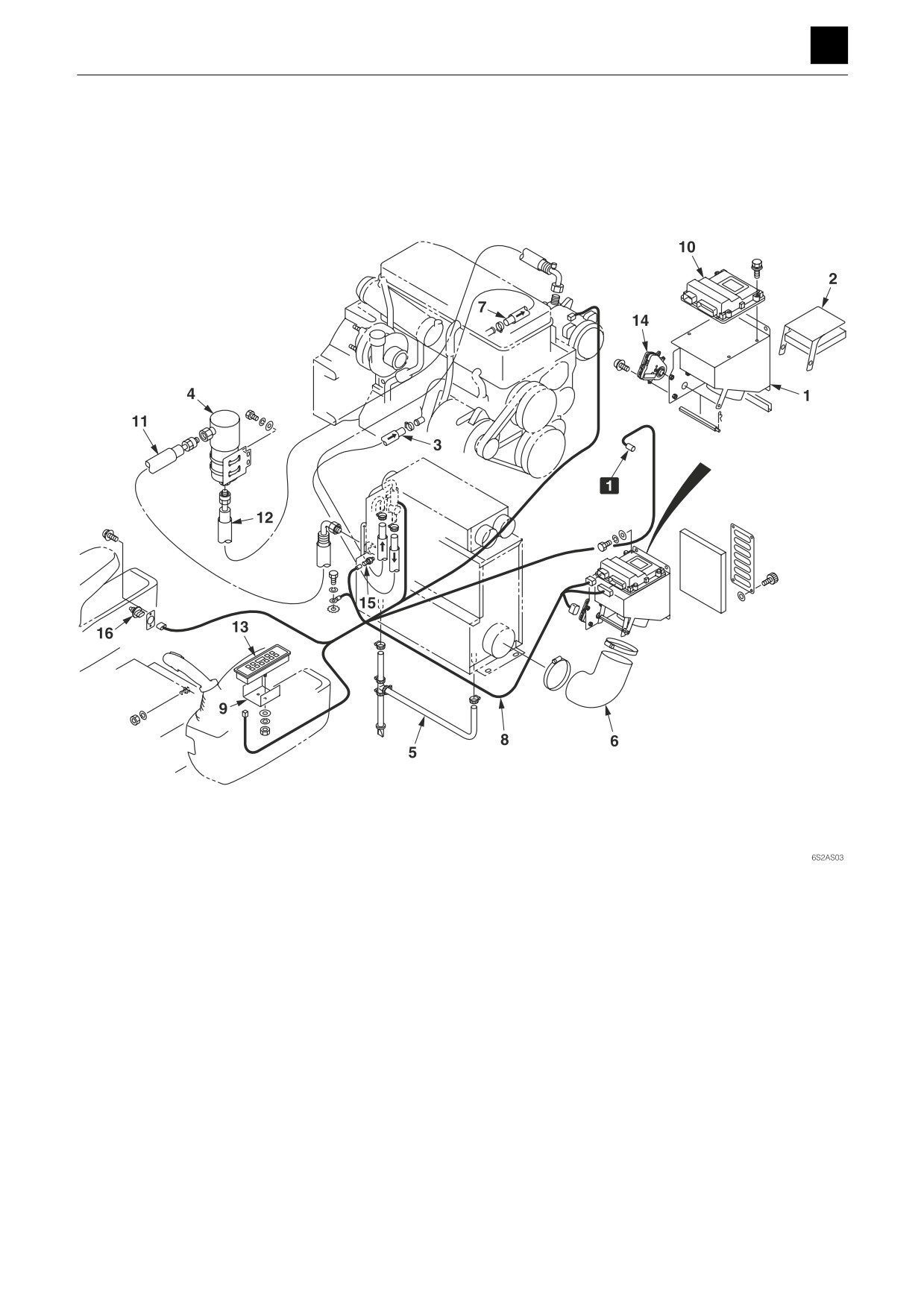
Air conditioner unit assembly 1
1 To transducer
1. Box
7. Hose
13. Control panel
2. Plate
8. Wire harness
14. Actuator
3. Hose
9. Bracket
15. Charge sensor
4. Accumulator
10. Controller
16. Thermosensor
5. Hose (Drain)
11. Hose
6. Hose
12. Hose
3
AIR CONDITIONER
6S2AS00
6
AIR CONDITIONER
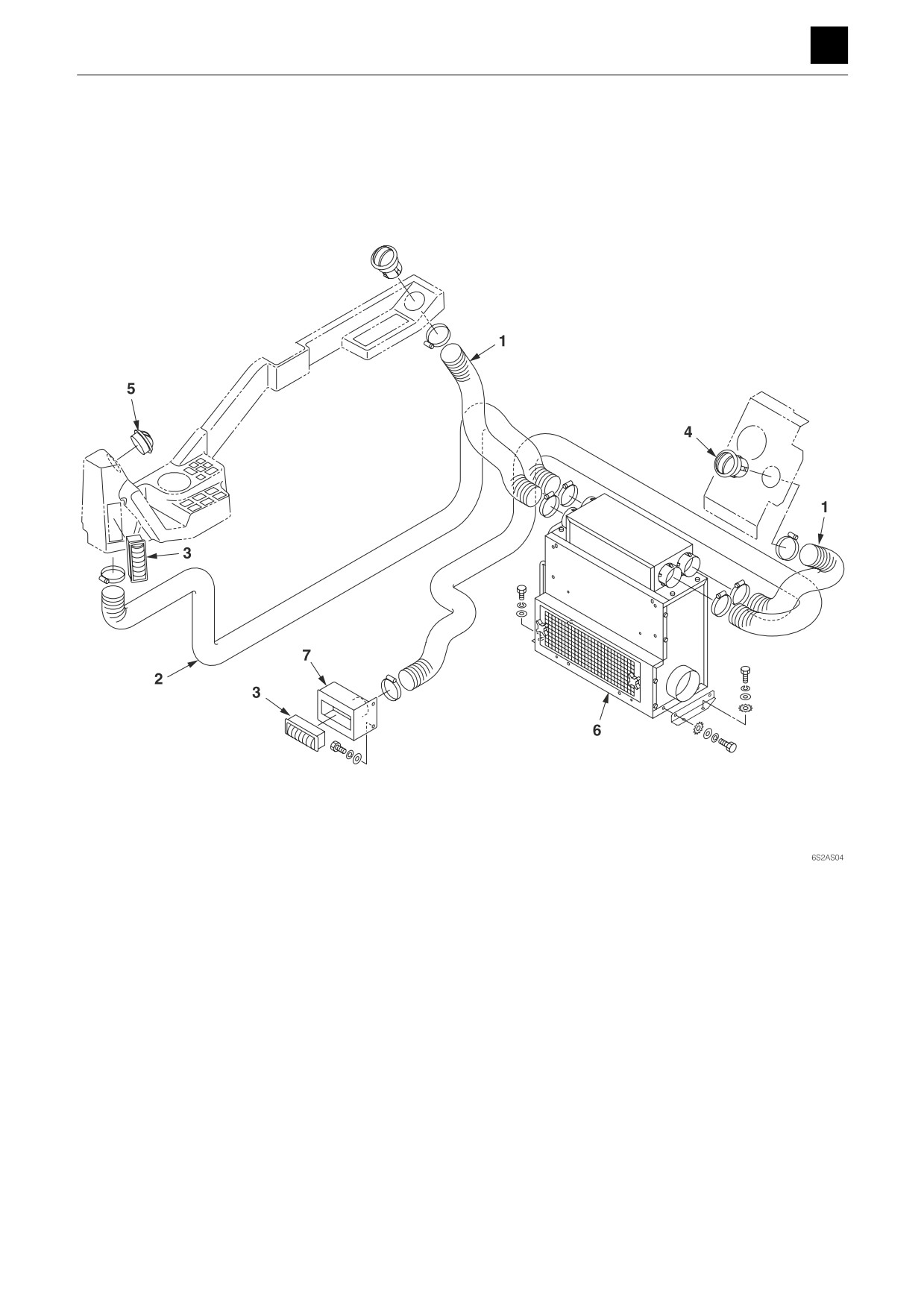
Air conditioner unit assembly 2
1. Hose
5. Louver
2. Hose
6. Air conditioner unit
3. Louver
7. Bracket
4. Louver
4
AIR CONDITIONER
6S2AS00
6
AIR CONDITIONER
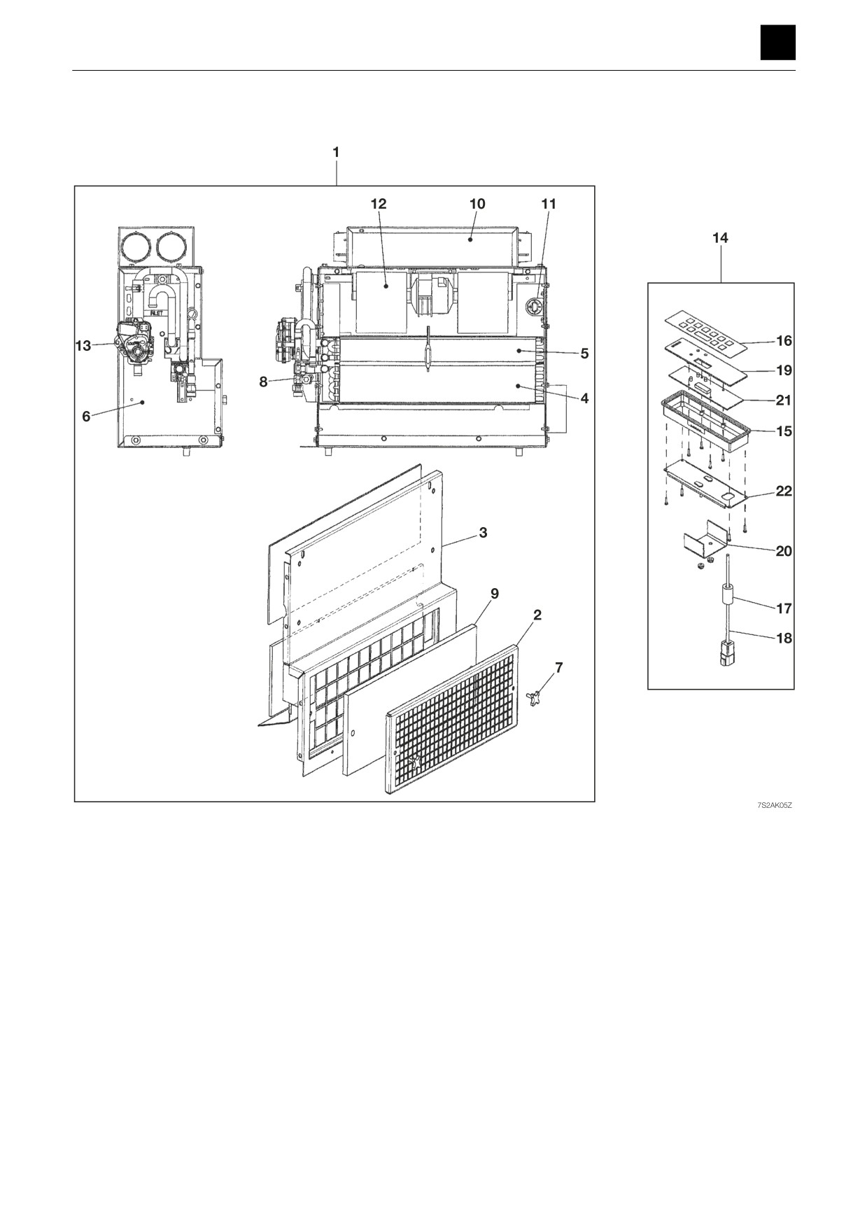
Air conditioner unit
1. Air conditioner unit
9. Filter
17. Core
2. Cover
10. Box
18. Wire harness
3. Cover
11. Thermostat
19. Panel
4. Evaporator
12. Motor
20. Bracket
5. Heater
13. Valve
21. PCB assembly
6. Housing assembly
14. Control panel
22. Plate
7. Knob
15. Box
8. Orifice
16. Plate
5
AIR CONDITIONER
6S2AS00
AIR CONDITIONER SYSTEM(RED DOT)
Overview of System Operation
• Truck and Heavy Equipment Systems
• Air Conditioner-System Operation
• Heater System Operation
• Environmental Effects on System Operation
• Chapter Review
Truck and Heavy Equipment Systems
A variety of HVAC systems are in use today, some old and some new. There are:
• Vehicle manufacturer installed systems
• Owner specified systems
• Add-on systems
• Retrofit systems
The system components come in different colors, shapes, and sizes. They may be
mounted in or on the cab in varied locations. Owners or fleet maintenance people can
modify systems by adding controls, auxiliary units or ducts. Major components are
sometimes replaced due to damage or failure. All systems were, at least originally,
designed and installed to meet the needs of an operator. Figure 2-1 includes illus-
trations of various AC and Heater systems. They illustrate system advantages and
disadvantages explained in the paragraphs that follow.
The HVAC system includes both heater and air conditioner components, usually
a common control, and air ducts. The system cools the cab by removing heat energy.
It removes moisture from damp air in the cab and adds fresh outside air to the cab. In
this way, the operator can work comfortably in all kinds of weather.
A sleeper unit, built in or added on, increases the air volumes in the cab. The air
conditioner or heater must circulate and cool or heat a larger amount of air. This is ac-
complished by routing ducts and controls to the sleeper compartment as part of system
design. Components may be increased in size to handle the larger cab air volume. A
bigger heater core, air conditioning evaporator coil, condenser, blower or fan may be
included. Often, on long haul trucks, auxiliary air conditioning and heater components
and controls are added. The objective remains the same, to move heat energy and
maintain occupant comfort.
System Operation
Air Conditioner—System Operation
We have described the movement of heat energy and basic HVAC system function in
Chapter 1. Now we will go into some detail on how an air conditioner operates. The
system is sealed to keep out air and moisture. To operate properly, the inside of the
system contains a measured amount of refrigerant and special refrigerant oil that keeps
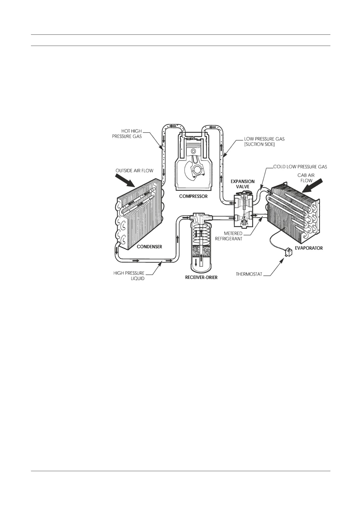
the system lubricated. Figure 2-2 is an illustration of system components without the
cab outline, in-cab controls, component housing, and air ducts or vents. Please study
it for a moment. Note the information printed next to each component. Remember that
the components may be positioned and attached to the truck in various locations.
Air Conditioner—System Operation
The following AC components are discussed in detail in this section:
1. Compressor/Clutch Assembly
2. Condenser
3. Receiver-Drier
4. Expansion Valve
5. Evaporator Coil
Figure 2-2
Air Conditioner components
are connected together to
illustrate system operation.
The components shown are
not to scale. The refrigerant
and refrigerant oil are clear
in color and not visible in
this drawing. The small ar-
rows inside the components
and connecting hoses show
the direction of refrigerant
flow (refrigerant circuit).
1. Compressor/Clutch Assembly
The compressor/clutch assembly is the heart of the system. When the clutch is engaged,
the compressor pumps refrigerant and oil around the system. It raises the temperature
and pressure of the refrigerant gas, and forces it to the condenser where it changes
state and becomes a liquid. The compressor also sucks the vaporized refrigerant out
of the evaporator and back inside itself in the form of gas. One way valves inside the
compressor separate the compressed gas (high pressure) side of the system from the
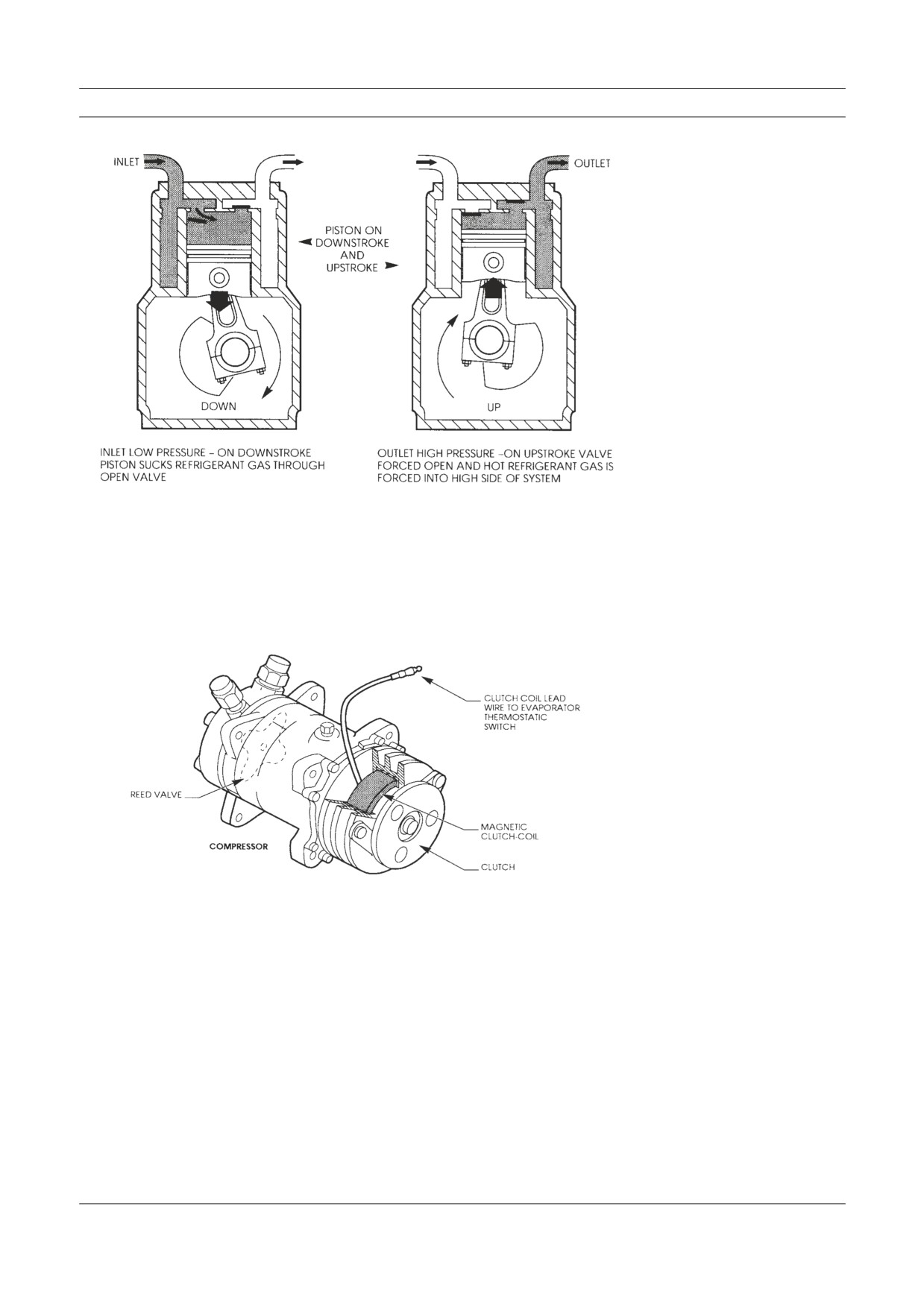
suction (low pressure) side. Figure 2-3 shows a cutaway view of a compressor with the
high and low pressure sides noted.
System Operation
Figure 2-3
The compressor inlet is
low pressure and the outlet
is high pressure. The reed
valves are one way. They
open to allow refrigerant gas
to enter the compressor on
the down stroke and exit on
the upstroke. Note the open
valves in the illustrations.
The clutch is mounted on the shaft of the compressor and is engaged by electromag-
netic action. Part of the clutch assembly is an electromagnetic wire coil. The coil is
energized through a thermostat that senses the temperature in the evaporator coil. If
the evaporator is too warm the electrical contacts close and allows power to flow to the
clutch. The compressor shaft is engaged and moves the refrigerant around inside the
system. Figure 2-4 is a cutaway view of the clutch mounted on the compressor.
Figure 2-4
The clutch shown here has
its electromagnetic coil
mounted on the compressor
body. When the coil is ener-
gized, magnetic force pulls
the clutch drive plate into
the pulley. This action locks
the pulley to the compressor
drive shaft and drives the
compressor.
2. Condenser
The refrigerant gas leaves the compressor and moves through a high pressure hose to
the condenser. Inside the condenser the gas “changes state” and becomes a liquid. It
is still hot and under pressure. Remember in Chapter 1 when we talked about water at
212 degrees Fahrenheit? Heat energy was involved in the “change of state,” but the
temperature did not change. The same kind of action happens inside the AC system.
The refrigerant gas gives up a lot of heat energy to the outside air as it “changes state”
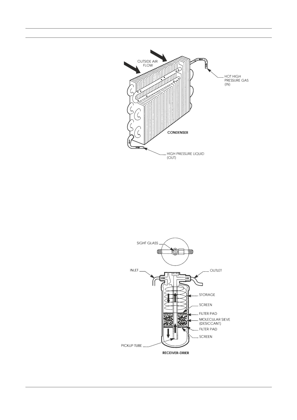
in the condenser. Figure 2-5 illustrates a condenser. Air moving through the condenser
absorbs heat from the refrigerant. The amount of air flow through the condenser is the
major factor in how well the condenser functions.
Air Conditioner—System Operation
Figure 2-5
As the refrigerant gas moves
through the tubing coil from
top to bottom, it condenses
(changes state) into a liquid.
For ease of installation,
condenser fittings are often
routed close together.
3. Receiver-Drier
The liquid refrigerant continues to move inside the system, out of the condenser
through a tube or hose to the receiver-drier. The receiver-drier serves as a small stor-
age tank and filter for the refrigerant. It is also a good location to mount pressure
switches and often contains a sight glass (small window) used to view activity inside
the system. The receiver-drier, Figure 2-6, also separates gas (bubbles) from the liquid
with a pick-up tube as shown in this illustration. Some receiver-driers have a spring to
preload the desiccant pack.
Figure 2-6
This cutaway view of a re-
ceiver-drier shows the filter
elements, inlet, outlet and
refrigerant path. The sight
glass is a small window into
the system used in diagnosis
and when adding refrigerant
(charging the system).
System Operation
4. Expansion Valve (Refrigerant Metering Device)
When refrigerant moves from the receiver-drier, it travels through another high pres-
sure hose to a metering device at the inlet of the evaporator coil. The metering device
can be an expansion valve, an expansion tube or a combination (multiple function)
valve. Between the compressor and this point inside the system, the pressure is high
and can range from 150 to 250 pounds per square inch. The expansion valve (TXV) is
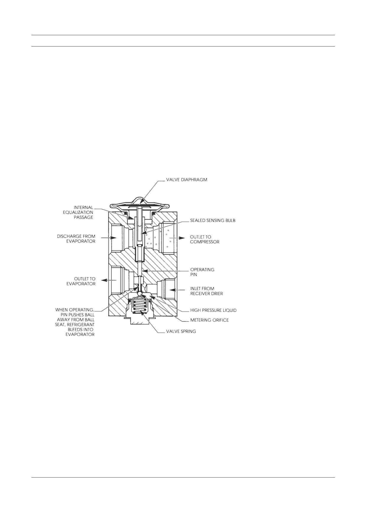
closely connected to the evaporator. A diaphragm opens the valve by exerting pressure
on the spring. Pressure comes from gas inside the diaphragm housing on top of the
valve and in the sealed sensing bulb. The sensing tube is located in the outlet of the
evaporator and picks up heat from warm refrigerant leaving the evaporator. The gas in
the valve diaphragm housing and sensing tube expands when it gets warmer and forces
the expansion valve open at the metering orifice.
Figure 2-7
This block type expansion
valve cutaway view will
give you a better idea how
these valves work. Spring
pressure holds the valve
closed.
5. Evaporator Coil
The expansion valve or other type of metering device bleeds high pressure refrigerant
into the evaporator coil, where the pressure is low. The refrigerant expands rapidly in
this low pressure environment. When it expands it “changes state”. The sudden drop
in pressure brings the refrigerant temperature down quickly inside the evaporator coil.
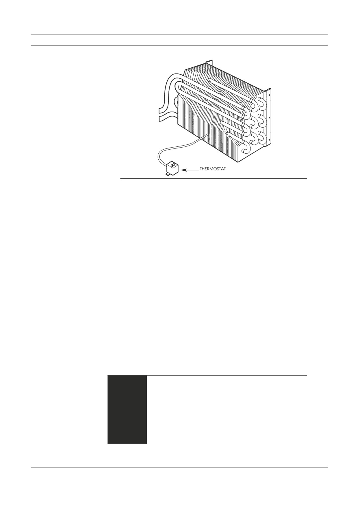
Figure 2-8 shows an evaporator coil and thermostat. Refrigerant is sprayed into the
evaporator by the high side pressure when the expansion valve opens. The refrigerant
absorbs heat from the air when the blower forces the air through the fins. When the
thermostat probe senses the upper limit of the thermostat heat setting, a circuit closes.
The compressor clutch engages and the compressor operates and moves more refriger-
ant to the high side of the system.
Air Conditioner—System Operation
Figure 2-8
The evaporator coil as
shown is of fin and tube
construction. The thermostat
probe is positioned in
between the evaporator fins
and senses the temperature.
Note: Moisture in the air (humidity) condenses on the fins of the evapo-
rator as water droplets which drain out of the evaporator through
a drain hose. This action dehumidifies the air in the cab as part of
system operation, and contributes to operator comfort.
Cab air forced across the evaporator coil gives up heat energy to the cold refrig-
erant inside the coil. The cooled air circulates in the cab for occupant comfort.
Refrigerant continues to expand and absorb heat energy in the evaporator coil.
Refrigerant changes from liquid to gas before it leaves the evaporator on the way
back to the compressor. The refrigerant gas moves to the compressor through a
low pressure (suction) hose. When the compressor is operating, it sucks the re-
frigerant gas back inside, compressing and raising its temperature and pressure.
Some of AC system operation is controlled by the operator, and some is automatic.
The operator can turn the system on and off, regulate the air velocity with the blower
control, and in some designs adjust the thermostat control. The system and component
operating range settings automatically cycle the clutch on and off. The operation of
the expansion valve or other refrigerant metering device at the inlet to the evaporator
is automatic.
Individual system features may differ, but the basic system function remains the
same. Variations in components and controls are described in Chapters 4 and 5. The
engine provides the power for both air conditioner and heater operation. It drives the
AC compressor and the cooling system water pump. Engine RPM affects the efficiency
of both the heater and air conditioner. The slower the engine RPM, the less capacity a
heater or AC system will have.
When an AC system is operating, the high pressure side com-
WARNING
ponents, fittings and high pressure lines or hoses can be hot
enough to burn your skin if you touch them. This includes the
compressor, clutch, hoses, condenser, receiver-drier, and any
control devices or metal tubing. The low pressure side will be
cool to the touch. In operation the AC system is under load
and high side pressures normally range between 150 and 250
pounds per square inch for R-12 and higher for some other
refrigerants.
System Operation
Heater System Operation
Heater and air conditioner systems both have the same basic function of moving heat.
They take advantage of nature’s laws where heat energy always moves from a warmer
to a cooler area. In a heater system there is no “change of state” involved in system
operation. The system is sealed and operates under pressure, but the pressure is low
when compared to an air conditioner.
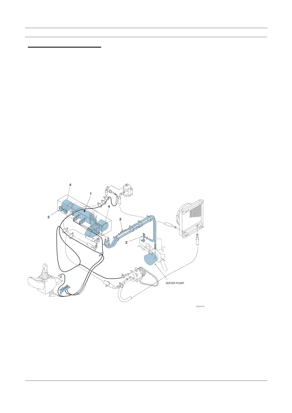
A heater system uses the engine coolant to carry excess heat energy to the cab air.
The heart of the system is the water pump. The water pump forces hot coolant through
a hose from the engine block and through the heater core. The coolant is returned to the
engine cooling system either at the suction side of the water pump or to the radiator.
The heater fan or blower forces cab air through the heater core where heat energy
moves from the engine coolant to the air in the cab. Figure 2-9 illustrates the main
heater system components. In-cab controls, component housing and air vents are not
shown.
The following heater components are discussed in detail in this section:
1. Heater Core
2. Water Valves
3. Defrosters and Ducts
4. Blowers and Fans
Figure 2-9
This view of a heater system
shows the main components
and how they are connected.
Additional heater controls, ducts, air vents, blend-air doors, temperature regulating
devices and auxiliary heaters may be installed as part of a heater system. These may be
air, vacuum, electrical or mechanically operated.
Environmental Effects
1. Heater Core
Heater cores are like small radiators. The fin and tube construction is designed to
route coolant flow for the best possible heat energy transfer from coolant to cab
air. Hoses from and to the engine are connected to the core with clamps. The core
outlet may be larger or the same size as the inlet.
2. Water Valves
Water valves may be cable, vacuum or air controlled. The valve can be either
open, closed or set part way open. Some valves have a bypass design to return
coolant to the engine. Most are manually controlled although electronic systems
are now being installed.
3. Defrosters and Ducts
Defrosting is accomplished by directing heated dry air through ducts to the
windshield. The heater system serves the dual purpose of defrosting and heating.
Controls are used to route the air flow to the windshield and occupant areas by
opening and closing duct doors. Controls may be manual, air or vacuum.
Many vehicles use a “defrost interlock” system which utilizes the air condi-
tioner to dry the defrost air and clear the cab windows more quickly.
4. Blowers and Fans
Blowers or fans are used in the system to move cab air through the heater core
and evaporator. Air can be pushed or pulled through the core depending on sys-
tem design. Blower or fan speed is usually selected by the operator.
Environmental Effects on System Operation
The environment outside the cab involves more than the weather. It may be hot and
humid or cold and dry. That is only part of the condition the HVAC system must handle
to maintain an ideal comfort range. A truck can be at idle, in traffic or moving along
for hours on the Interstate at 65 M.P.H. The load condition on a trip can include going
out full, coming home empty, or driving across the Rockies or Kansas plains during
the day or night. The truck color and shape, the windows and angle of the sun are all
variables that can increase or decrease the “load” on the system. The following are a
few examples of environmental effect:
• A black cab-over (COE) with a dark color interior will be more dif-
ficult to cool than the same vehicle with white paint and a light colored
interior. The black cab picks up and holds the radiant heat from the sun
more easily than the white one.
• In Florida or Houston the humidity in mid summer can be very high
with the temperature in the high 90’s or low 100’s. The AC unit must
remove a lot of moisture from the air in the cab as the air moves through
the evaporator fins. The more moisture on the fins, the less effective the
transfer of heat is to the refrigerant inside the evaporator coil.
System Operation
• On a cold day the temperature can drop below zero. The engine may
run cooler so the engine coolant is cooler when it circulates through
the heater. The heat in the cab moves out of the cab faster (remember
heat always moves to a cooler area until both are the same tempera-
ture—nature’s law). To maintain cab comfort you have to increase the
flow of coolant through the heater, increase coolant temperature, and/or
move more air through the heater core.
• On a hot day, an off-road vehicle experiences cooling at a slower rate
than an on-road vehicle. This is a result of high sun-load, large window
area and often less insulation.
It is important for you to keep environmental effects in mind when you are servicing
or diagnosing heater or air conditioner systems. If you work in Denver the altitude will
affect system function and pressure. In Houston the heat and humidity may lower heat
transfer to the air at the condenser and increase system operating pressures.
Chapter Review
•
HVAC systems range from simple cab heaters to multi-function com-
bination systems. The multi-function system can heat and cool the cab
and sleeper unit, and have separate auxiliary components and controls
for driver and passenger comfort.
•
Both heater (engine) coolant and air conditioner refrigerant circulate
inside sealed, pressurized systems. The normal air conditioner operat-
ing pressure ranges from 150 to 250 pounds per square inch, sometimes
higher with a different refrigerant.
•
Air conditioners have a high and a low pressure side within the system.
The compressor is the starting point of the high side. Pressure drops at
the expansion valve opening to the evaporator.
•
The basic components of an AC system are the compressorclutch as-
sembly, high pressure lines, condenser, receiver-drier, expansion valve,
evaporator, thermostat, blower assembly, and suction lines. There may
be other controls installed for more complex systems.
•
The basic components of a heater system are the inlet and outlet hoses,
a water valve and valve control, heater core and fan or blower assembly.
There may be other controls for more complex systems.
•
An air conditioner system uses the “change of state” of refrigerant inside
the system to move heat from the cab air to the outside air. Refrigerant
changes from a gas to a liquid in the condenser, and back to a gas in the
evaporator.
•
A heater system uses the heat from the engine, carried to the heater core
by the action of the water pump, to warm the air in the cab. There is no
change of state within the heater system.
•
Environmental conditions affect how both heaters and air conditioners
work. Weather, driving conditions, color of the vehicle are factors. All
contribute to heat gain or loss inside a cab and how much heat energy
must be moved to maintain occupant comfort.
Inspection and Maintenance-
without gauges
• Discussion of Inspection & Maintenance Survey Results
• Visual Inspection - System Off
• Electrical System Inspection
• Performance Inspection - Engine Running
• Heater System Inspection
• Preventive Maintenance Worksheet
• Chapter Review
Discussion of Inspection & Maintenance Survey Results
There are three reasons for regular inspection and maintenance procedures:
1. They save money in the long run by reducing down time and often
prevent more costly repairs.
2. They help to insure driver comfort and safety.
3. They add to your store of knowledge about these systems and main-
tain your level of efficiency.
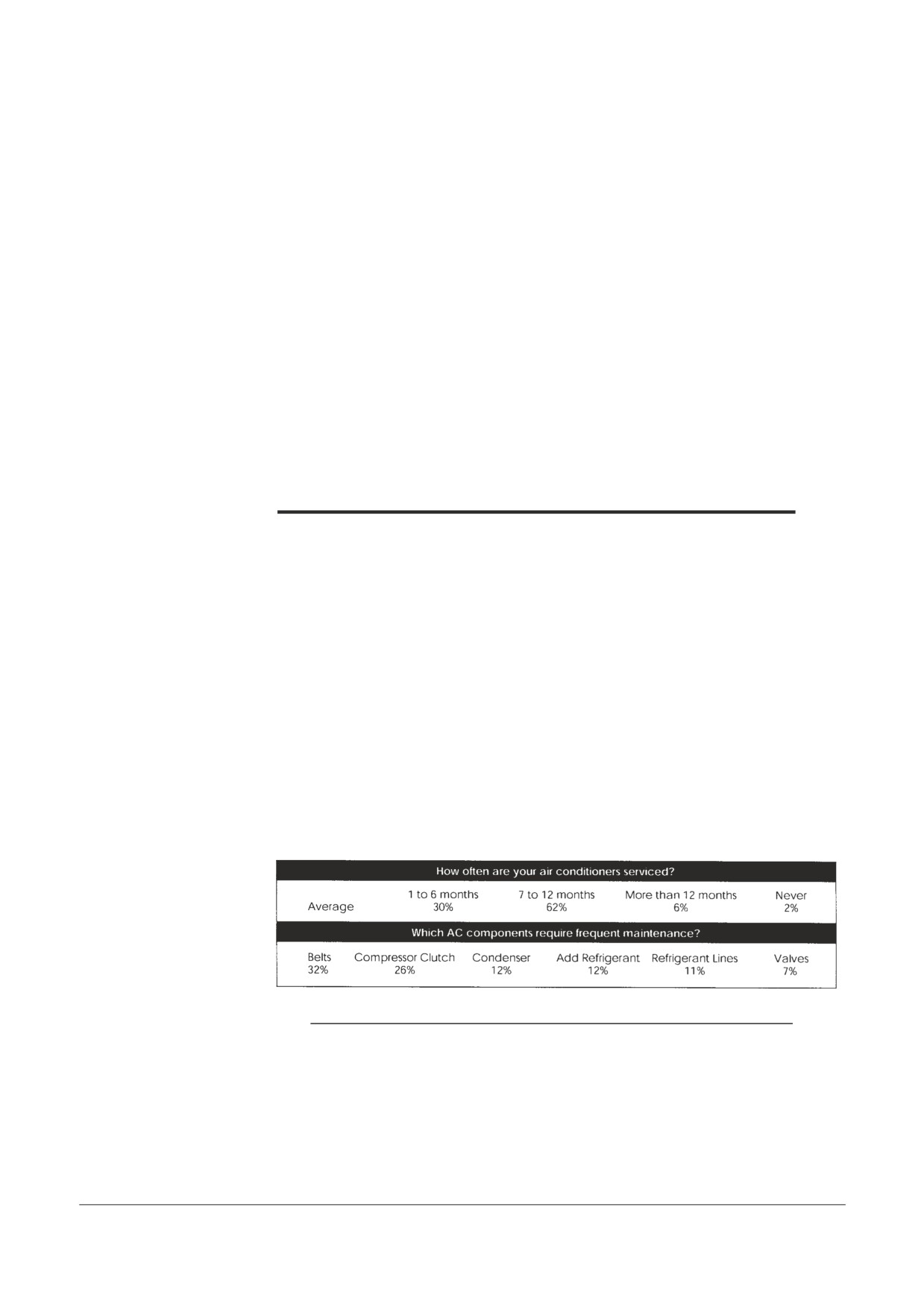
About half of all heavy duty vehicles have air conditioners. Surveys of AC system
owners find that over 30% of the systems are serviced every six months or less, and
another 62% are serviced at least once a year.
The survey also covered how often the different components required maintenance.
Figure 7.1 below shows survey finding percentages. Failure of any of the AC compo-
nents listed in the survey could cause a system to malfunction or stop cooling.
INSPECTION & MAINTENANCE SURVEY
Figure 7-1
This chart shows mainte-
nance frequency, lists key
parts and how often they
require maintenance.
Note: The above survey results may not apply to your situation. Actual
operating conditions for the vehicles you service will determine
or influence maintenance frequency and requirements.
The following inspection procedures should take about 15 to 20 minutes, longer if
corrective steps, part replacement or adding refrigerant is necessary. There is a “Pre-
ventive Maintenance Worksheet” you may use at the end of this chapter, Figure 7-9
Inspection & Maintenance
Visual Inspection - System Off
Your observations and the corrective measures you take may be different depending
on circumstances. The following inspection procedures are explained in more detail
below:
1. Observe the System
2. Inspect Parts
3. Check Hoses and Fittings
4. Check for Refrigerant Leaks
Use the following procedures as a general rule in performing a visual inspection with
the AC system off:
1. Observe the System
Your first inspection step is to answer the following question if you can:
• Has the vehicle just come in off the road and has the HVAC system
been in use?
• Did the operator or work order explain or describe any problems
about the system?
• Did someone else work on the system yesterday, 700 miles down the
road? Your first inspection step is to answer these questions if you
can.
Even when someone has told you what is wrong with an HVAC
CAUTION
system, you should perform a visual inspection. Always make
a visual inspection before you hook up the manifold gauge set.
Never add refrigerant to a system until you have made a com-
plete visual and performance inspection.
2. Inspect Parts
Look at the system for what might come loose, leak, wear out or become dirty
and not function the way it should. The main points for visual inspection of the
system are emphasized in Figure 7-2.
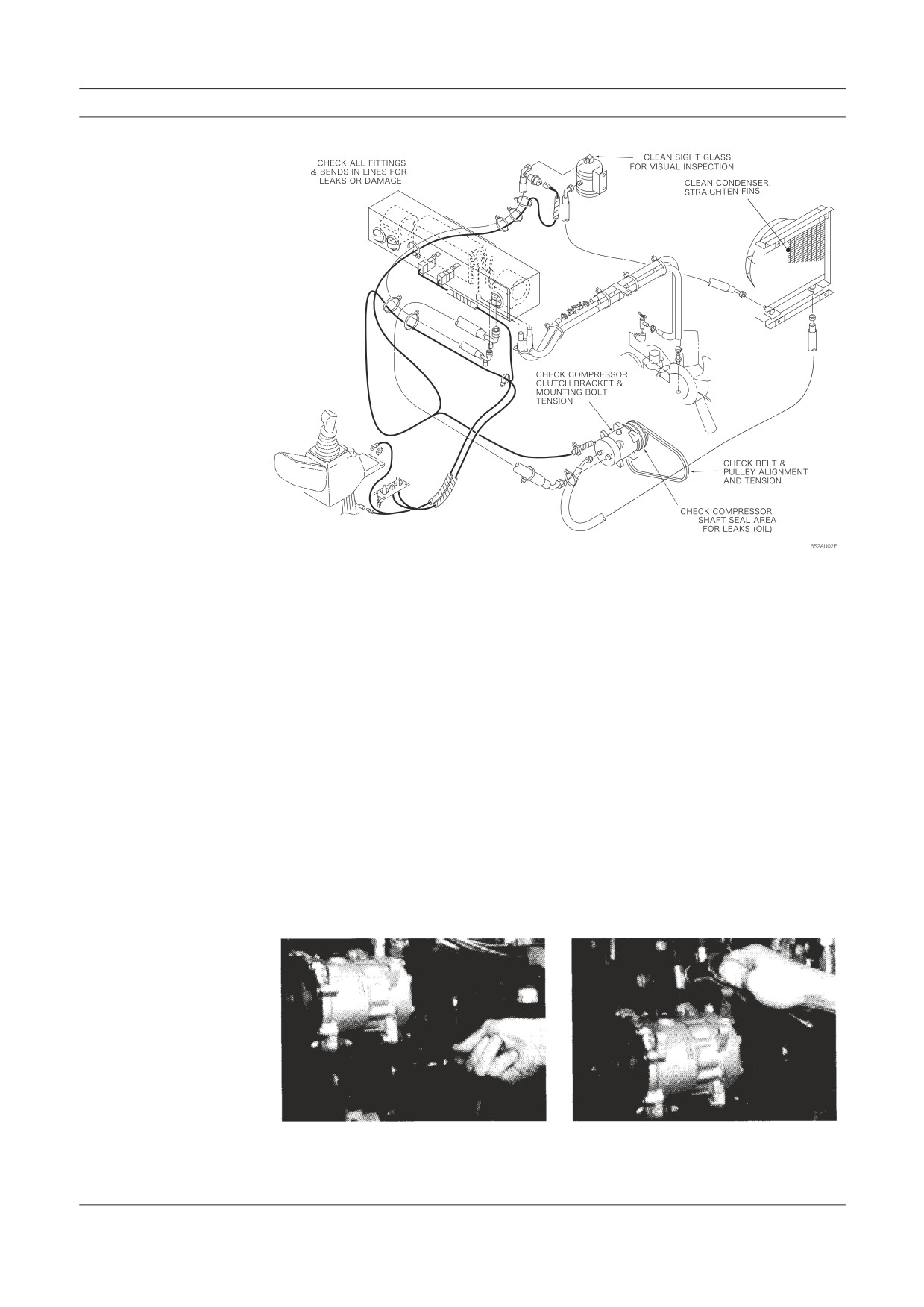
Visual Inspection
Figure 7-2
This system illustration
notes the main points for
visual inspection.
A. Condenser - Is it free of leaves, bugs, bird feathers or mud? The condenser must
be relatively clean to work well as a heat exchanger. How you clean the condenser
depends on where it is mounted. The condenser fin comb, air hose and nozzle, or
soap and water may be used. Where possible, check condenser mounting bolts or
screws and tighten them if necessary.
Condenser failure often results from loose hoses. Hose movement will cause
fatigue failure of condenser tubing adjacent to the fittings. Make sure the hoses are
securely clamped.
While inspecting the condenser check the receiver-drier sight glass and connec-
tions. Look to see if the sight glass has a moisture indicator that is showing moisture
in the system.
B. Components Under the Hood - Tip the cab or raise the hood. Look at the
compressor mounting bracket, compressor clutch assembly, drive belt and pulley
alignment. The mounting bracket, compressor, clutch and drive pulley should be
fastened securely, and a clutch groove (there may be two groves) should be in line
with the drive pulley. Tighten all bolts shown in Figure 7-3, as you inspect.
Figure 7-3
Engine and compressor
vibration can work mount-
ing bolts loose. Tighten
all mounting bolts as you
inspect the system. Slots in
the mounting bracket are
used to move the compressor
clutch assembly in order to
adjust belt tension or align-
ment.
Inspection & Maintenance
C. Drive Belt - The drive belt should be tight and in good condition. Use a belt ten-
sion gauge to check tension (120 pounds maximum). With experience, you can feel
belt tension by twisting the belt. Try feeling belt tension after using the gauge, when
you know the tension is correct. Replace belts if they are frayed or look worn.
If the clutch pulley/belt alignment is obviously off, you need to loosen the com-
pressor or mounting bracket, or both—and use the alignment bar to line up the clutch
pulley with the drive pulley. Tighten compressor mounting bolts first, then the bolts
holding the bracket. The mounting bracket should have slots or other means of
adjustment to allow you to adjust the tension of the drive belt. When you use a pry
bar to apply tension, be sure you do not pry against the compressor. Pry against the
mounting bracket.
3. Check Hoses and Fittings
Check all hoses and fittings. Look for places where hoses flex when the cab is tilted.
Any places the hoses or fittings are fastened, clamped, connected, bent or secured are
potential wear points. This also applies to places where hoses are not clamped or sup-
ported but should be (often near the condenser). All of these spots are potential leak or
damage points. Tighten, re-fasten, add, or replace as indicated by your inspection.
4. Check for Refrigerant Leaks
System refrigerant leaks can be anywhere but there are obvious places. You can spot
some by looking for signs of refrigerant oil forced out with refrigerant leakage. One
location leaks frequently occur is the compressor shaft seal. The shaft and seal are
hidden behind the clutch assembly, but centrifugal force will throw the oil off the
shaft and against the engine, bracket or whatever is close. Check these points when
you examine the compressor clutch and mounting bracket. A solution of soap and
water applied around potential leak points works well for detecting leaks. A leak in the
evaporator may be indicated if you feel around the condensate drain hole and find oil
present.
Note: You can add inexpensive dry nitrogen gas to the system instead of
R-12 if system pressures are low. Dispense the gas at no more than
200-250 PSI as this is sufficient pressure to cause or indicate a leak
point in the AC system. AC service procedures for complete system
recovering of refrigerant, evacuating, and recharging are covered and
illustrated in
Note: A leaking heater core could also result in coolant at the condensate
drain.
Electrical System Inspection
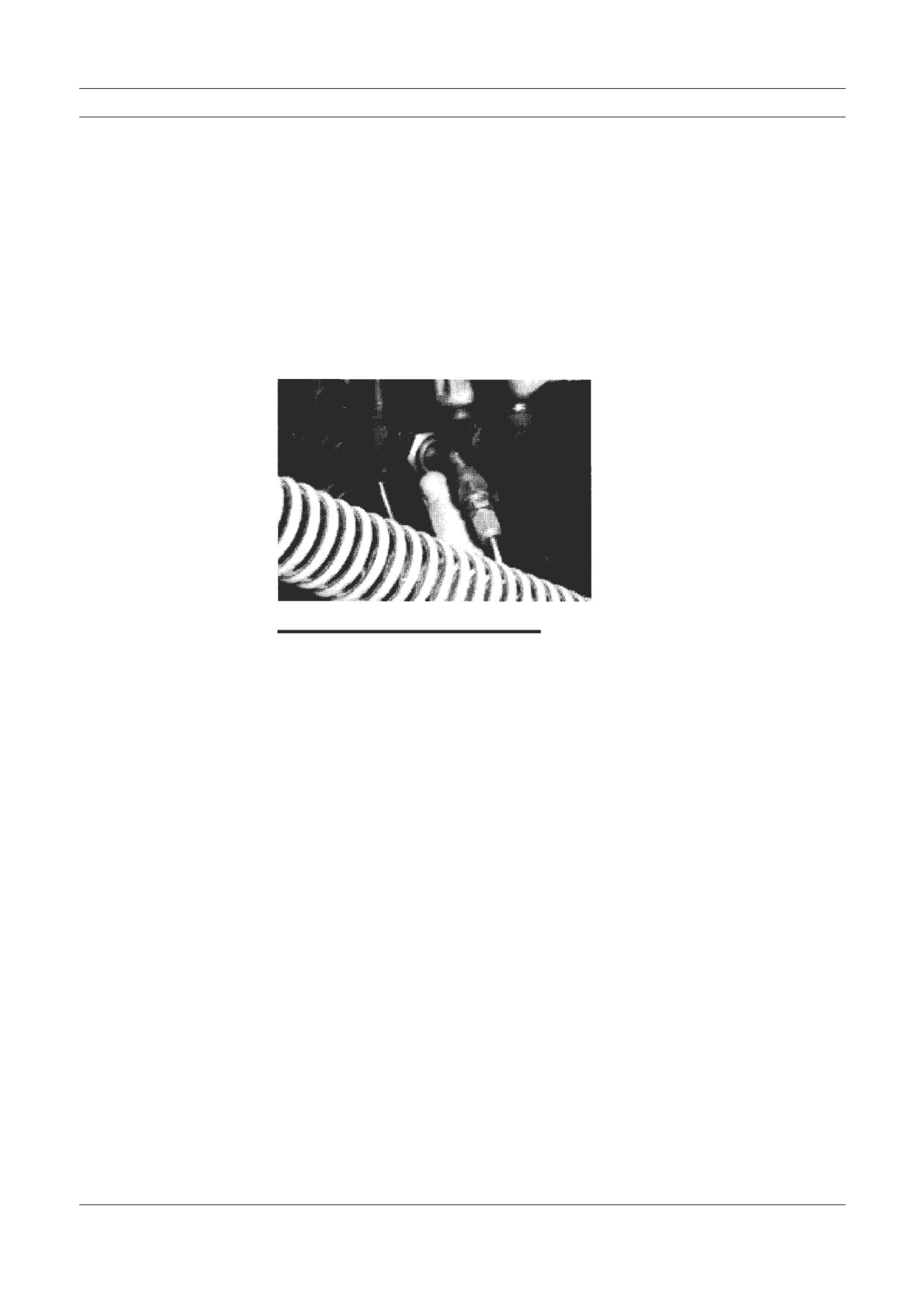
You can feel for oil at the bottom of all connections (see Figure 7-4) if the system
is not too hot. Of course, a few minutes with an electronic leak detector is the
best way to check for leaks. Keep in mind that pressure is different in a system at
rest, so small leaks may be hard to find. Pressure in a system at rest, will equalize
at from 60 to 95 PSI, depending on outside air temperature. This means there is
more pressure in the low side of the system at rest than during normal system
operation. Just the opposite is true of the high side; at rest, high side pressure is
lower. You may want to use the detector to check for leaks in the high side when
the air conditioner is operating, if you suspect a leak and can’t find it when the
system is at rest.
Figure 7-4
This illustration shows a po-
tential refrigerant leak point
at the condenser fitting.
Electrical System Inspection
The two stages of an electrical inspection are explained in more detail below:
1. Inspect Electrical Connections
2. Check Electrical Current Flow and Device Functions
Use the following procedures to perform an electrical system inspection:
1. Inspect Electrical Connections
First, while you are making your visual inspection under the hood (cab) and/or at
the roof top condenser, take a moment and check all electrical connections visu-
ally and by feel. Look for any corrosion on leads or connectors and clean them.
Make sure all leads and wires are properly supported and securely connected.
2. Check Electrical Current Flow and Device Functions
Perform the following steps to check current flow and electrical device func-
tions:
A. Turn the Ignition On - To check current flow the ignition must be on.
Inspection & Maintenance
B. Turn the AC System On - This will power the thermostat and clutch.
If it does not come on, use the AC mode switch to check the leads to the
switch. You should be able to hear a “click” from the thermostat and hear
the clutch drive plate “snap” against the clutch pulley. You can not check
thermostat cycling on and off until you do the performance inspection. Fig-
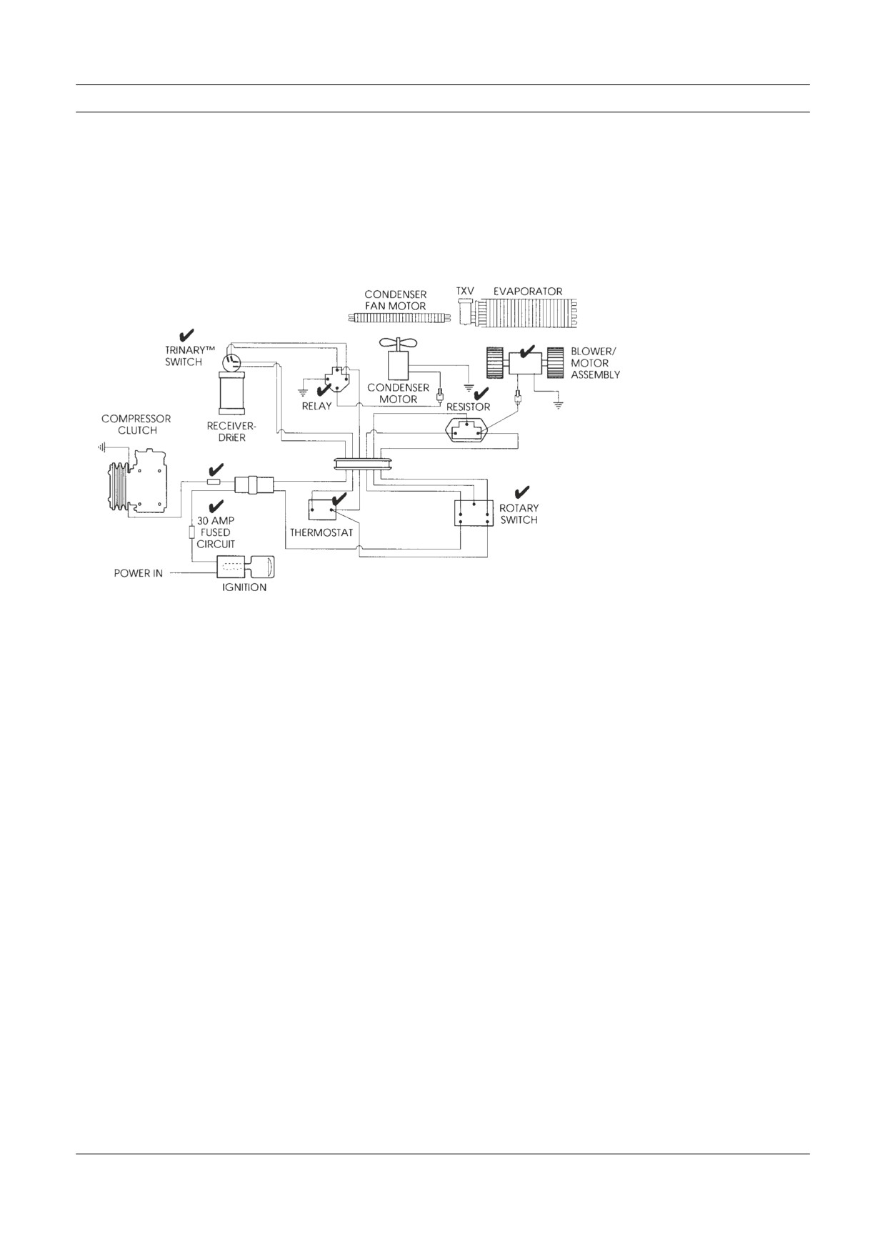
ure 7-5 illustrates a typical AC electrical system and the places you should
inspect.
Figure 7-5
The electrical system inspec-
tion points are noted with
check marks (✔) on this
wiring diagram (electrical
schematic).
C. Check Fuses - If there is a failure and you have made sure all con-
nections are clean and tight, you need to check fuses—in-cab as well as
in-line.
D. Check Clutch Engagement - Since you can’t see and may not hear the
clutch engage, get out and look at the clutch. If it’s engaged, you will see
that the drive plate is against the pulley and not slightly spaced from it. If
you are not sure the clutch is engaged, look for the lead wire connector near
the clutch. Break and close that connection. The clutch will disengage and
engage again.
E. Test Blower Speed Operation - Some systems have a common switch
that turns on the air conditioner and powers the blower motor. Test blower
speed operation by adjusting this or the separate blower control switch.
Feeling the air flow from the ducts or note blower sound (speed) changes.
F. Inspect Roof Mounted Condensers - Don’t forget to inspect roof
mounted condensers and AC systems for dirt and debris. Be sure the con-
denser fan(s) are working properly and all parts and electrical connections
are securely fastened. The roof mounted condenser fans may come on when
the system is turned on. Like the thermostat and most clutches, the normal
on-off cycling action can not be observed until the engine is running with
the AC system on.
Electrical System Inspection
Performance Inspection - Engine Running
The purpose of visual and electrical inspection is to detect obvious problems and assure
AC system function for an accurate performance inspection. If you do the performance
inspection first, you could be mislead. Problem areas discovered during the perfor-
mance inspection can give you false clues or symptoms, and result in repair errors and
come-backs. The following performance inspection procedures are explained in more
detail below:
1. Inspect System Component Cycling and
Cab Temperature Levels
2. Check Clutch Cycling Under Load
3. Check Sight Glass
The performance inspection does not cover pressure and temperature sensitive safety
devices (cutout switches, fan control, Trinary etc.). Testing these devices requires the
use of the manifold gauge set for observation of internal system pressures during tests.
These are explained in
Use the following procedures as a general rule in a performance inspection:
1. Inspect System Component Cycling and Cab
Temperature Levels
A. Turn On the Engine and Air Conditioner - Inspect for system compo-
nent cycling and cab temperature levels.
Note: System performance testing will be much faster if all doors
and windows in the cab are closed.
The cab air must cool down to thermostat control setting lev-
els before system components will cycle on and off, indicating
correct function. This is called ‘stabilizing the system’ and takes
about five minutes of operation. In very hot weather the system
may not cycle.
B. Check Thermometer Readings - In the cab you can use your thermom-
eter to measure air temperature at the vents. When the evaporator is easy to
reach with a thermometer probe without removing some of the dash or duct
work, use the probe to measure evaporator temperature. When the AC unit
is on and working correctly, you can see the thermometer dial needle move
down to about 32 degrees, then rise six to ten degrees and move back down
again. The movement up and down indicates that the cycling clutch and
thermostat, or orifice tube and accumulator pressure switch (to the clutch)
are functioning correctly. In systems with a non-cycling clutch, this move-
ment indicates correct function of the refrigerant metering device.
The needle movement is called “temperature swing.” When you can ad-
just the thermostat setting, the range of swing should change. For example,
from full cooling (cold) to moderate (between cold and warm), the swing
may change from 32-38 to 32-42 degrees.
Inspection & Maintenance
These readings at the vents will be higher and temperature swing slower
and not as obvious. Also blower speed will cause the temperature, levels to
read higher (high air speed) or lower (low air speed) at the same thermostat
setting. When you measure air temperature, an electronic thermometer/py-
rometer is a great tool to have. You can easily measure cab air temperature
at several locations quickly.
Swing temperatures vary depending on where you measure temperature,
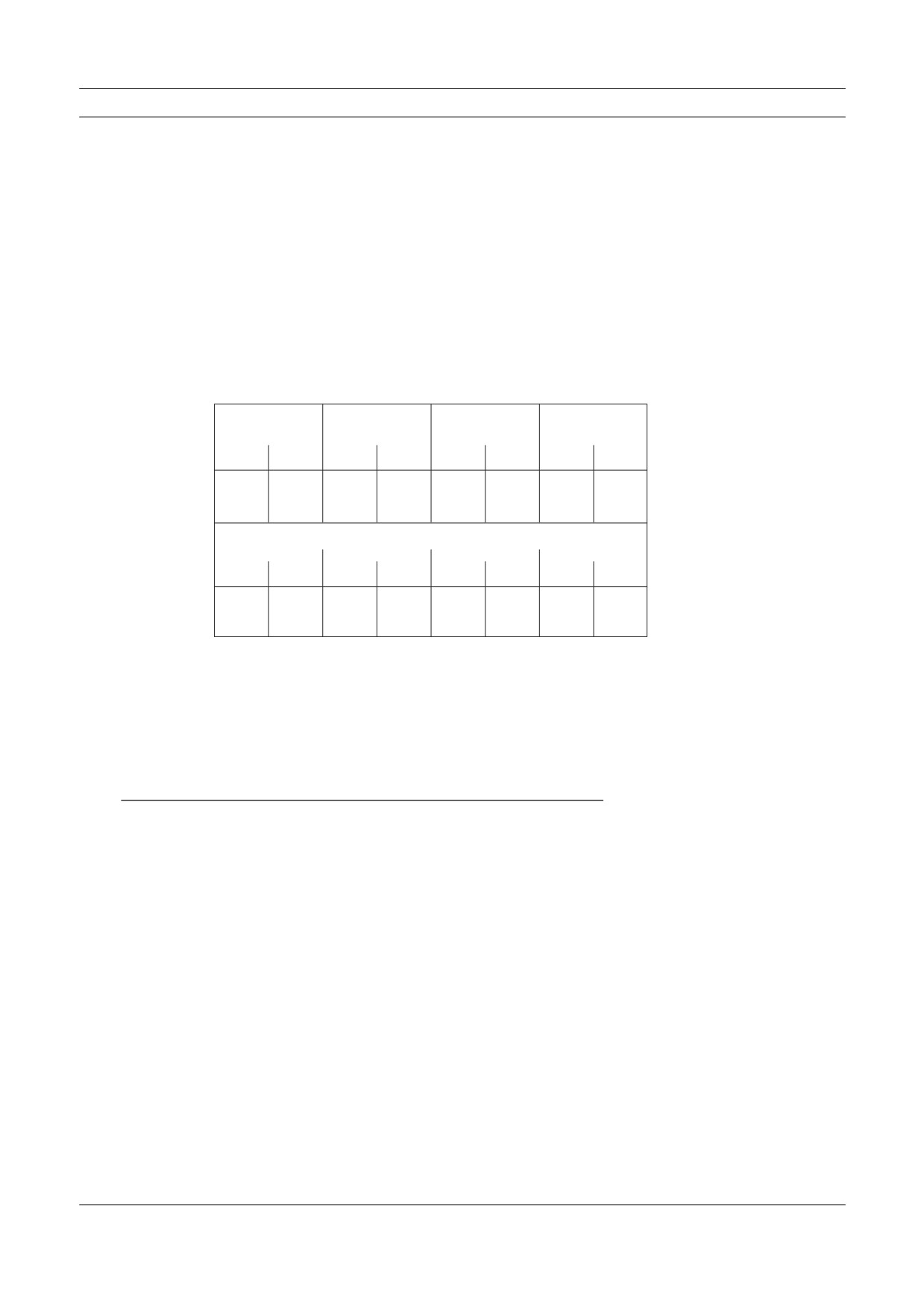
and on outside temperature, humidity and altitude. The chart in Figure 7-6,
shows some examples of typical temperature variables. Don’t forget that
cab and sleeper area temperatures can vary within the same vehicle. Also,
electronic controls used in newer HVAC systems often keep the tempera-
ture spread within a narrower range.
Figure 7-6
air temp.
70°
80°
90°
100°
degrees f.
The chart of AC system and
cab temperature range shows
air quality
humid
dry
humid
dry
humid
dry
humid
dry
you typical variables.
center outlet
43°
40°
44°
40°
47°
40°
52°
41°
air temp.
to
to
to
to
to
to
to
to
degrees f.
47°
44°
48°
44°
51°
44°
56°
45°
left & right air outlet temperature will vary
left
right
left
right
left
right
left
right
outlet air temp.
40°
41°
41°
43°
46°
47°
48°
50°
range degrees f.
to
to
to
to
to
to
to
to
41°
44°
45°
47°
52°
54°
55°
56°
2. Check Clutch Cycling Under Load
The following operating inspections, visual and by feel, are done outside the cab
while you wait for the system to stabilize.
A. Lift hood - With the hood up (or cab tilted) observe the clutch cycling
under load.
Note: If the condenser is hood mounted you may not have adequate air
flow through it.
B. Touch suction and discharge lines - Soon after system start up you can
safely feel the suction and discharge lines and note their change in tempera-
ture. The discharge line will get hot (after a while it may be to hot to touch)
and the suction line will get cooler.
3. Check Sight Glass
The sight glass is the only point where you can actually see inside the air condi-
tioner during operation. Check the sight glass through the window on the top of
the receiver-drier (or the separate in-line sight glass). If the system is functioning
properly and cooling the cab adequately, the sight glass should be clear (you will
not see anything in it). If it is not clear when the system is first turned on, wait a
few minutes for the system to stabilize, then look again. Figure 7-7 illustrates and
explains what you may observe in the sight glass. Roof mounted condenser fans
may run continuously or cycle on and off. If you can’t tell by sound you may have
to climb a ladder and observe the fan blades.
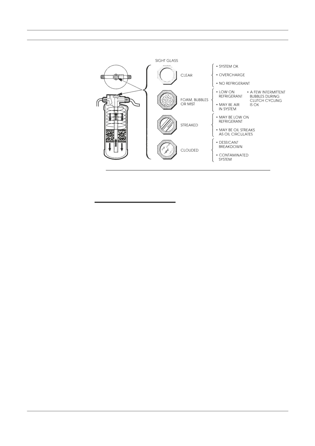
Performance Inspection
Figure 7-7
These drawings illustrate
conditions you may observe
in the sight glass window.
Note: A roof mounted condenser or AC unit assembly often includes
a roof mounted receiver-drier (and sight glass) close to the con-
denser.
Heater System Inspection
A heater system inspection is really a combination engine cooling system and heater
inspection. All heater/cooling system rubber parts deteriorate due to the air (ozone),
heat, coolant and oils. They should be replaced at regular intervals to prevent break-
down on the road. Metal parts and gaskets are subject to malfunction or breakdown
due to fatigue and corrosion.
Coolant has a limited life and should be replaced regularly. If it is dirty, the cool-
ing system should be drained and flushed or back flushed (using special equipment)
before refilling with clean water and anti-freeze. Coolant must be hot when using the
hydrometer to check protection (freeze-up) level. The following inspection procedures
are explained in more detail below:
1. Check Heater Control Valve Function
2. Inspect Other Functions
1. Check Heater Control Valve Function
Many air conditioner/heater systems depend on the heater control valve for tem-
perature control and positive closure. You can easily check heater control valve
function as follows.
A. Cool engine - Start with the engine cool, set the temperature to cold and
leave the fan off. As the engine warms up, feel the heater return hose. If the
hose feels warm or hot, the heater control valve is leaking internally. This
type of leak can seriously reduce air conditioning performance.
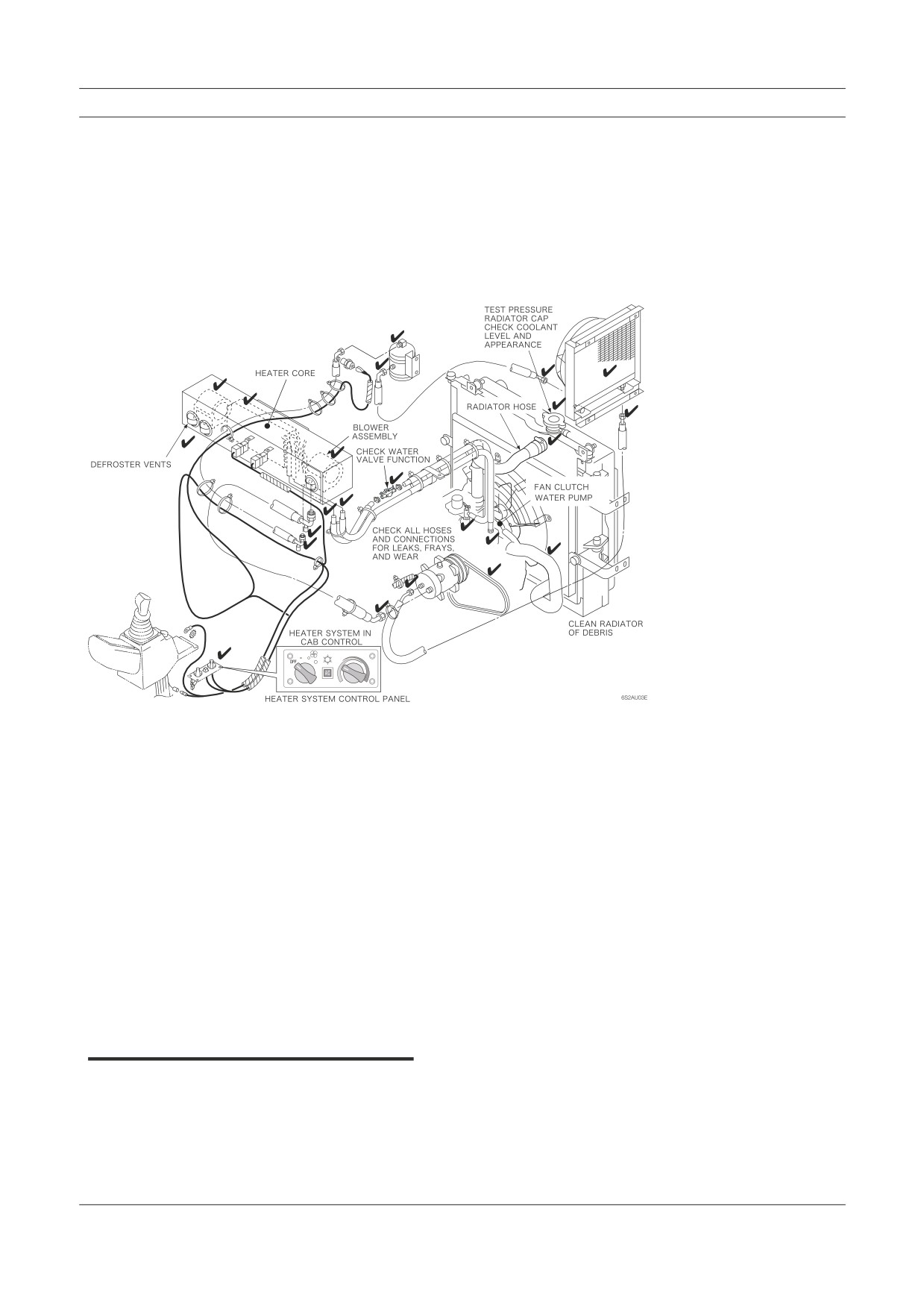
Inspection & Maintenance
B. Warm up engine - Next, let the engine warm up to normal operating
temperature and set both fan and temperature on high. Feel both heater sup-
ply and return hoses. If there is a noticeable difference in their temperature,
it indicates a low flow of coolant through the heater core (a partially closed
or blocked heater control valve). This could result in poor heating perfor-
mance during cold weather conditions.
Figure 7-8
Heater/cooling system
potential problem areas and
checks are indicated in this
drawing.
2. Inspect Other Functions
There are some things you can’t see or feel when you inspect the thermostat,
heater core, radiator pressure cap, electrical switch and control valve functions.
Some of these can be checked with the pressure and thermostat testers as de-
scribed in Chapter 6. A hand pump pressure tester can also be used to check for
coolant leaks. This is done by using the pump to raise the pressure inside the
system above normal operating pressure to force small suspected leaks to show
up.
Heater/cooling electrical and valve component inspection is the same as air
conditioner inspection. The controls are operated to see if they function correctly
to maintain or vary cab temperature and air flow.
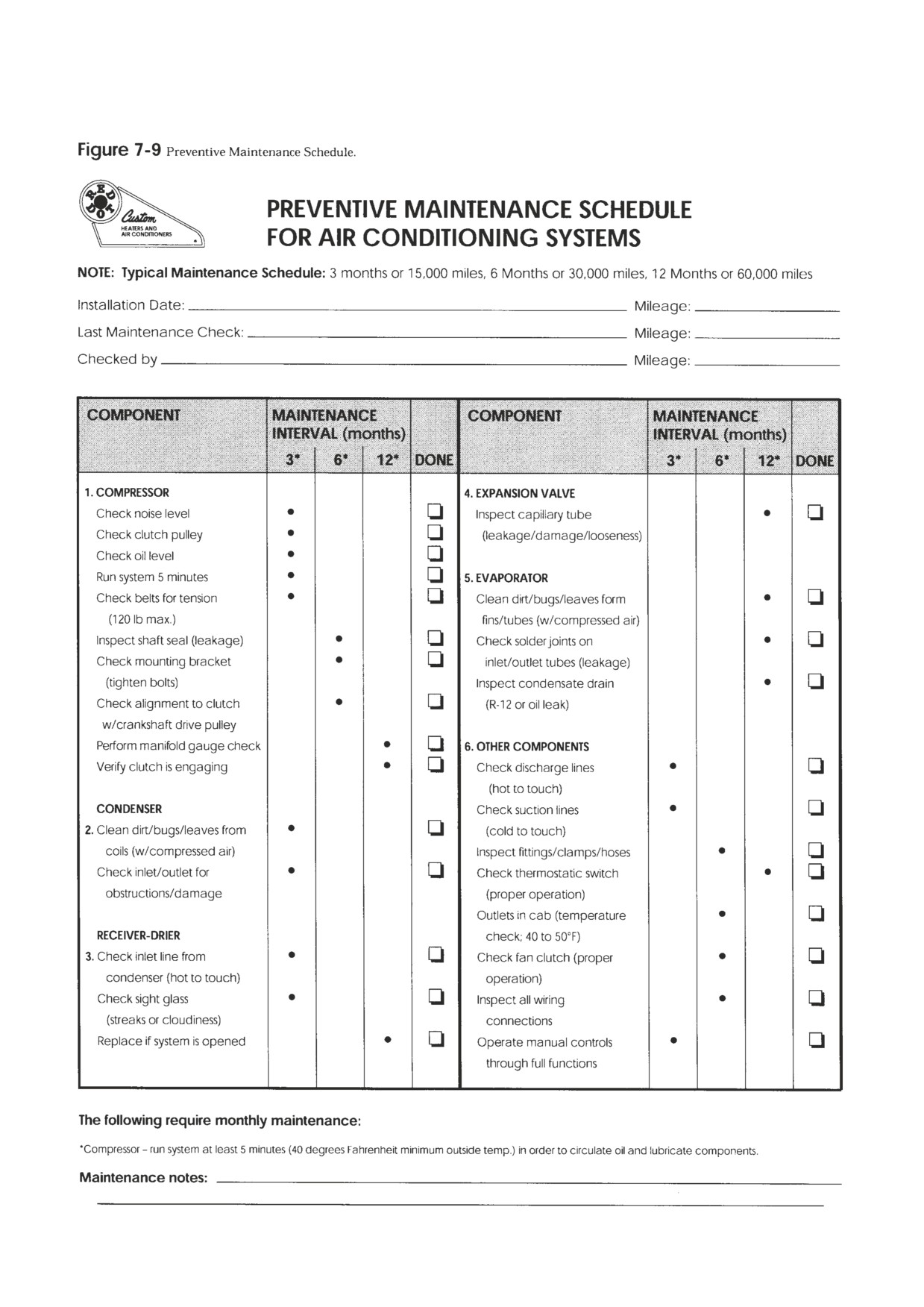
Preventive Maintenance Worksheet
Please feel free to modify or copy the worksheet in Figure 7-9. Actual vehicle use, mile-
age, operating conditions and maintenance budget may influence service frequency.
Chapter Review
Chapter Review
The purpose of these brief inspection procedures is for vehicle system maintenance
and to determine if further, more detailed service is required. The uses of a manifold
gauge set, system troubleshooting, recovery, flushing, evacuating and charging are
explained in the next chapter.
High usage and operating condition variations are tough on air conditioning and
heater components. You should establish and follow regular inspection and mainte-
nance procedures to improve overall system function and component service life.
The typical inspection should not take more than 15 to 20 minutes unless com-
ponent replacement and/or complete system evacuation and recharging is warranted.
The survey results shown in Figure 7-1, indicate belts, compressor clutch assembly,
condenser and the refrigerant lines are the most frequent problem areas. However,
your own experience with service and maintenance may vary from survey results.
Inspection should first be visual and by feel. Some of your electrical system inspec-
tion will be done as you inspect other components (checking leads, connections and
for loose wires). When you check the electrical circuit, begin with the engine off but
ignition on. A system performance inspection with the engine running and system on
really combines electrical and AC or heater system function.
Troubleshooting
& Service Procedures
• Troubleshooting Overview
• Understanding System Function
• A Troubleshooting Example
• Manifold Gauge Set Installation
• Troubleshooting by Manifold Gauge Set Readings
• Review of Frequent Problem Areas
• Conclusion
Can you fix an air conditioner or heater system without finding and correcting the
cause of the problem? You bet you can! It happens every day and it’s not good for
business. Here is an example. A truck pulls in off the road and the operator asks to have
his rig serviced in a hurry. He tells you the air conditioner isn’t cooling like it should
and dashes into the restaurant for lunch.
You tip the hood, and check the sight glass on top of the receiver-drier. You see
bubbles, not a lot but a fairly constant stream of them. It is obvious the system is low
on refrigerant so you hook up the manifold gauge set, purge the gauge set hoses of
air, and add refrigerant until the sight glass clears. Then you check evaporator tem-
perature and it’s OK. The air conditioner is repaired right? Wrong! What you did is
add refrigerant and the problem went away. You did not find and fix the cause of the
problem.
Component failure in an air conditioning system may be the result of a problem
elsewhere in the system. For example, a belt or clutch failure might be caused by a
dirty condenser restricting air flow and increasing head pressures. High head pressures
commonly create problems with other system components. Take time to look beyond
the obvious for a potential hidden problem.
Troubleshooting Overview
Troubleshooting includes collecting enough information to locate the cause of the
problem, then correcting the problem and its cause by replacement, adjustment, and/or
repairing. You begin by gathering information from the most to the least important
sources.
Starting with the most important:
1. Your personal knowledge and experience with AC systems.
2. The vehicle operator's knowledge and experience—question him or her.
3. The work order.
4. Good test equipment and the HVAC system
The routine you follow when troubleshooting should proceed from the most to least
productive way of locating the problem and fixing the cause.
Troubleshooting & Service Procedures
Experienced troubleshooters talk to the operator if they can, then personally verify the
symptoms of the problem whenever possible. They attempt quick fixes on the basis
of their knowledge of common system problems and causes when appropriate. They
know where components are located, and make repairs when they have a good idea
of what the problem is. They fix the cause or causes as well as the problem. They are
confident of their knowledge and ability.
Note: The best troubleshooters all know who to call when they get
stuck. They know someone who knows more than they do and
are not too proud to ask for help or suggestions when needed. The
key—understanding system function
The Key-Understanding System Function
Your complete understanding of AC and heater systems and how they work, plus
what can go wrong, is the key to troubleshooting and repair. We have talked about
components and system function before. Now let’s take a little different approach in
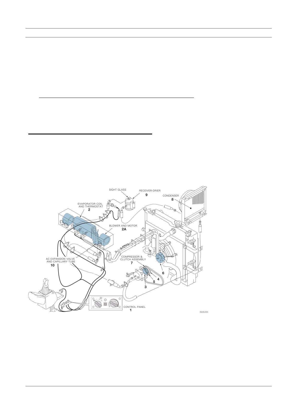
describing what happens when the air conditioner is turned on. In Figure 8-1 we have
used numbers on the illustration to track normal air conditioner function.
Figure 8-1
An illustration of the typical
HVAC system. The numbers
follow the action when the
AC part of the system is
working properly (moving
heat out of the cab and into
the outside air).
Understanding System Function
When you turn on the air conditioner at the control panel (1), the thermostat (2), is
supposed to sense a warm temperature at the evaporator. A circuit in the thermostat
should close, allowing current to flow through the thermostat to the compressor clutch
field coil (3). When this happens, the clutch field coil becomes an electromagnet and
pulls the clutch drive plate (4) tight against the clutch pulley (5).
Note: The same AC switch (1) may also turn on the fan or blower motor
(2a) to circulate air in the cab. The air feels warm at first but will
cool quickly.
A belt connects the clutch pulley to a drive pulley (6) on the engine. The engine pro-
vides the power to turn the clutch pulley and drive the compressor (7) when the clutch
is engaged. When operating, the compressor compresses and pushes refrigerant gas
to the condenser (8), through the receiver-drier (9), and to the expansion valve (10)
orifice. When it does, it puts a lot of pressure on the gas. The compressor raises the
temperature and pressure of the refrigerant inside the high side of the system.
At the same time, the compressor is also sucking in low pressure refrigerant gas
from the expansion valve orifice, evaporator and through the low side of the system.
The movement of the refrigerant inside the system transfers heat energy from the cab
to the outside air for occupant comfort.
The automatic functions of the thermostat (or the pressure valve on some accumu-
lators), and the expansion valve, help maintain pressures and temperatures inside the
system at safe and efficient operating levels. Pressure and temperature are constantly
changing due to compressor and expansion valve action, the amount of heat energy
being moved and the environment or weather conditions.
The engine cooling system fan and clutch (11), and the evaporator blower motor
(2a), move a sufficient amount of air through the condenser and evaporator. On the
road, vehicle speed provides most of the (ram) air required for the condenser to work
right. In a parked or slow moving vehicle the engine fan (or roof or remote mounted
condenser and fans) moves sufficient air through the condenser fins.
Note: Clean refrigerant and refrigeration oil should be inside the system
in the amount specified by the manufacturer. Moisture, sludge
(moisture combined with refrigerant oil or desiccant), or desic-
cant particles will prevent the correct performance of the system
and may cause component damage.
A Troubleshooting Example
Remember the story at the beginning of this chapter? The vehicle operator pulled in
off the road and asked you to repair the rig. He was in such a hurry he didn’t tell you
anything except that the air conditioner wasn’t cooling. Here is the best way to handle
that kind of situation.
Troubleshooting & Service Procedures
Use your knowledge and experience. Ask yourself what could have caused a lack of
cooling in that rig! Did the compressor drive belt break? Did a pressure switch or
relief valve cutout the compressor because of high or low system pressure? Does the
switch or valve in this type of system reset itself? Could there be a superheat switch
and thermal limiter with a melted fuse. Did someone else service the system recently
and put in too much refrigerant?
Could there be contaminants in the system blocking the expansion valve (expan-
sion tube)? If there is a leak, why and how did refrigerant get out of the system? You
know if refrigerant can get out, air and moisture may get inside as well, especially if
the leak is on the suction side of the system. Could there be a restriction to refrigerant
flow in one of the high pressure lines because of a kink? From your knowledge and
experience, you already know about these possibilities and others when you talk to the
operator (before he has the chance to leave).
The right kind of questions can speed up troubleshooting and your service work
by pinpointing the problem(s) that needs fixing. Your conversation with the operator
might be as follows:
•
Answer: About an hour ago.
•
What steps did you take when you noticed the lack of cooling?
Answer: I put it on maximum cool.
•
Then what did you do?
Answer: When it wouldn’t cool, I opened the window and turned
the air conditioner off.
•
Is this problem new or has it happened before, and when?
Answer: In the last few days I’ve had problems with cooling off
and on—this is the first time it’s happened when I was close to a
place that did AC service.
•
Do you get any cooling at all?
Answer: Yes but it seems to quit after a while.
•
Do you still get air flow at the vents from the blower?
Answer: Yes.
•
When was your air conditioner checked thoroughly?
Answer: Before I bought the rig last May (a year ago).
•
Answer: Yes.