Takeuchi Hydraulic excavator TB1140 (Serial No. 514400002~). Operator's Manual - page 14
A Troubleshooting Example
•
Answer: No.
•
(If the answer was yes, you should ask—When? Where?
What was fixed or replaced?).
• Finally, ask the operator if he or she has a wiring diagram for the
system.
Now let’s look at the information you have gathered from the operator and what you
know from experience. He believes the problem is that the AC system quits cooling
after it has been on for a while! You know that the AC system has not been maintained
since the rig was purchased a year ago. Because of that, there could be several causes
for the problem (lack of cooling) and there may be other potential problems about to
develop.
It is possible that some refrigerant has leaked. Moisture and other contamination
may be inside the system. You have been told there are no heater problems, but that
doesn’t mean there are none that might affect AC system operation. The AC system
has quit cooling several times in the last few days. The problem may have become
more severe than when it quit cooling the first time.
If enough refrigerant or oil has leaked out, a low pressure cutout switch may have
cut the circuit to the clutch, protecting the compressor. Because the system has not
been maintained in a year, there may be other components that should be serviced. You
could fix the probable causes, and the system might work and then break down again
as the rig drives out of your place. From your knowledge and what the operator has just
told you, you know this may not be a quick fix problem.
It’s up to you to describe the service situation to the operator. Tell him you need to
do a complete system maintenance inspection to find and correct the problem or other
potential problems. He can give you the go ahead for full service and repair now, wait
till you have inspected the system to determine cause and cost, or delay repair until he
has some down time available.
Normally when the operator can tell you what the problem is, you would first oper-
ate the system to verify the problem. In this situation your troubleshooting (your own
knowledge added to what the operator told you), indicates the next step. You need to
do a complete maintenance inspection instead! Proceed as described in Chapter 7.
Correct any obvious problems and check carefully for leaks. Leak testing should be
visual, by feel and with a leak detector. Next, do your performance test with the engine
running and the AC system on.
Note: Don’t forget to check the heater system too! If the water valve
is not closed, then hot engine coolant flowing through the heater
core would warm the air at the same time the evaporator was
trying to cool it. The result would be the appearance of an AC
problem.
Troubleshooting & Service Procedures
If your AC and heater visual, electrical and leak inspections don’t turn up any problems,
save time by hooking up the manifold gauge set before you make the performance test.
If you find a leak and can correct it easily by tightening a connection, do so. But if too
much refrigerant leaked out, you may have to add some refrigerant to the system for an
effective performance test. We will get into detail on troubleshooting with gauges after
we explain manifold gauge set installation and adding refrigerant.
Manifold Gauge Set Installation
Never hook up the gauge set when the engine and air con-
CAUTION
ditioner are running. Be sure all the valves on the manifold
are closed all the way (turn them clockwise). Check the hose
connections on the manifold for tightness.
Locate the low and high side system service fittings and remove their protective caps.
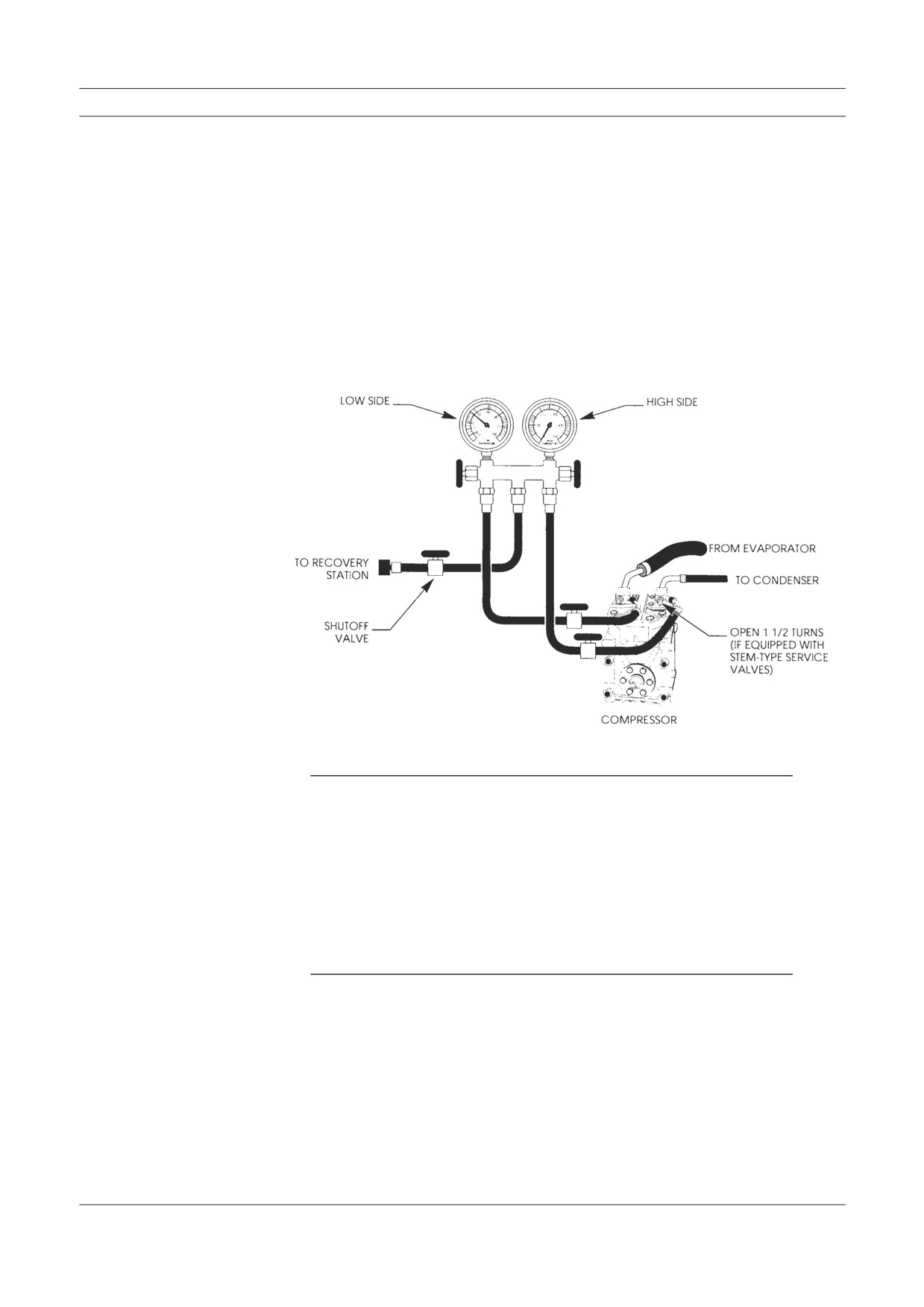
Position or hang the manifold gauge set in a convenient location. Figure 8-2 illustrates
a good example of manifold gauge set hookup in one service situation.
Figure 8-2
A typical manifold gauge
set hookup is shown in this
illustration. The center hose
on the gauge set is con-
nected to the vacuum pump.
The manifold gauge set is a necessary tool in troubleshooting AC system problems.
The following steps are performed during and after installing the manifold gauge set:
1. Purging Air from the Gauge Set Hoses
2. Adding Refrigerant to the System
3. Stabilizing the AC System.
Manifold Gauge Set Installation
1. Purging Air From Gauge Set Hoses
Environmental regulations require that all service hoses have a shutoff valve
within 12 inches of the service end. These valves are required to ensure only a
minimal amount of refrigerant is lost to the atmosphere. R-12 gauge set hoses
have a valve near the end of all three hoses. R-134a gauge sets have a combina-
tion quick disconnect and shutoff valve on the high and low sides. The utility
(center) hose also requires a valve.
The initial purging is best accomplished when connected to recovery or re-
cycle equipment. Figure 8-3 illustrates the gauge set connections for purging and
refrigeration recovery.
Figure 8-3
The purging setup for
manifold gauge set and
compressor service valves
are shown here.
Note: The manifold gauges read system pressure when the hand valves
are closed if the hose end valves, and the stem type service valves
(if included) are open.
2. Adding Refrigerant to the System
Now that the gauges are connected, you may need to add some refrigerant to the
AC system before you can do an effective performance inspection. However, if
leaks are obvious they should be repaired prior to adding refrigerant.
Note: Loss of some refrigerant is not unusual over an extended period
of time. Adding refrigerant is a typical procedure when the AC
system is maintained on a regular basis.
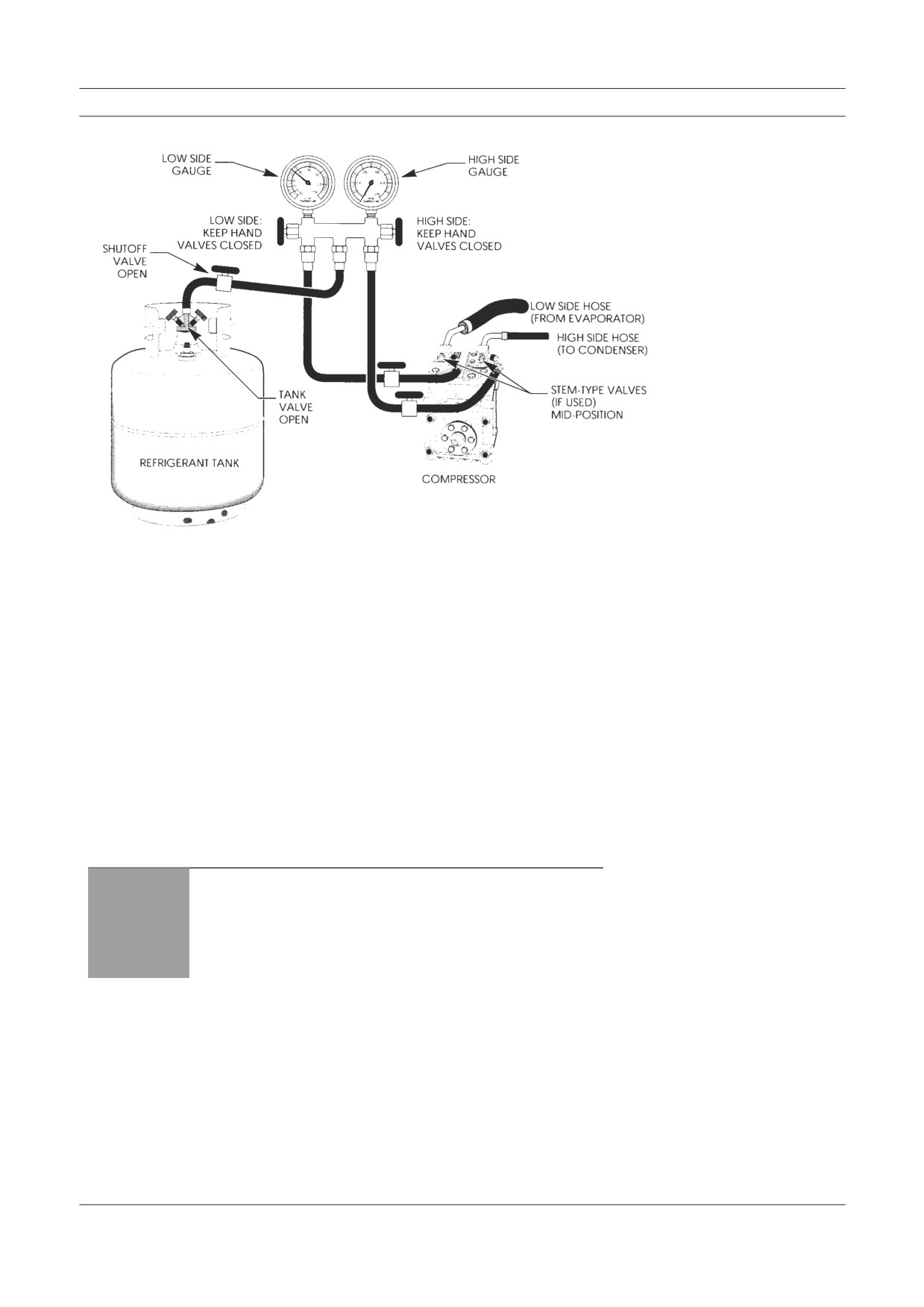
When adding refrigerant to the system, connect the center hose from the mani-
fold gauge set to the refrigerant dispensing valve on the container. Figure 8-4
illustrates this connection.
Troubleshooting & Service Procedures
Figure 8-4
In this illustration we have
noted how refrigerant is
added to the air conditioner.
Before adding refrigerant to the system you should study the sight glass while the
engine is running and the air conditioner is on. Even if you found a leak during the
system inspection and corrected it, you have no way of knowing how much refriger-
ant has leaked. You will not be able to tell how much refrigerant is in there, but you
can see if bubbles are present.
Then check the gauges for unusually high or low readings, or a lack of pressure.
Following this procedure, and using your knowledge and experience, decide if it
is safe and makes sense to add refrigerant in order to make your full performance
inspection.
You are now ready to add refrigerant to the system. For your safety and to
prevent system damage use the following procedure.
1. Turn on the engine and set the idle at 1200 to 1500 RPM and then turn
on the air conditioner.
Do not open the high pressure hand valve on the manifold
CAUTION
gauge set. The compressor could pump refrigerant into the
container and cause it to BURST. Be sure to keep the refriger-
ant container upright to prevent liquid refrigerant from enter-
ing the compressor.
2. Open the refrigerant dispensing valve on the container and then the
low pressure hand valve on the manifold. This allows refrigerant to
enter the system as a gas on the low pressure or suction side of the
compressor. The compressor will pull refrigerant into the system.
Manifold Gauge Set Installation
3. Add refrigerant until the gauges read in the normal range and the sight
glass appears clear. The sight glass may not be clear for a moment just
before or after the clutch cycles on and off but should generally be
clear. Gauge readings will fluctuate as the compressor cycles on and
off.
Note: Pressures within the air conditioning system vary with ambient
temperature. A normal pressure range is defined as follows:
Low side
15-30 PSIG
High side
150-280 PSIG
If R-134a is used in place of R-12 the high side readings will
be about 20 PSI higher. For this reason many OEMs are recom-
mending an increase in condenser capacity when retrofitting to
the new refrigerant, R-134a.
If the gauges show any abnormally high or low pressures as
CAUTION
you are adding refrigerant, stop and investigate for probable
cause. Never add more than one pound of refrigerant. If the
system is low enough on refrigerant to require more than that
amount you should stop and check again for leaks. Then re-
cover all of the refrigerant, repair, evacuate and recharge the
air conditioner. (See Chapter 9). You may want to add dry
nitrogen gas to the AC system instead of R-12 if pressures are
below normal and a leak is suspected. Nitrogen gas is sold in
cylinders under high pressure, 1800 to 2000 PSI. Be sure the
cylinder has a pressure regulating valve to control the pressure
when dispensing nitrogen gas. Dispose the gas at no more than
200-250 psi, as this is sufficient pressure to cause or indicate a
leak point. See note under Troubleshooting by Manifold Gauge
Set Readings in this chapter.
4. When the gauges show normal, close the hand valve on the manifold,
the hose end shutoff valve, and the valve on the refrigerant container.
You can now proceed with the performance inspection.
3. Stabilizing The AC System
For reliable gauge readings as an aid in troubleshooting, the AC system must be
stabilized.
CAUTION
Be sure your tools and test equipment are clear of all moving
parts of the engine and air conditioner.
Troubleshooting & Service Procedures
Start the engine and set to a fast idle of 1200 to 1500 RPM. Turn on the air con-
ditioner. After a quick in-cab performance test of control function, blower speeds
and air flow, set the AC system controls to maximum cooling and blower speed
on high. All windows must be closed. If cab temperature is hot (rig has been sit-
ting in the sun with the windows closed), open the windows for a minute or so to
let the hot air out. Run the engine and air conditioner about five minutes for the
system to stabilize. In hot humid weather or where the AC condenser can’t re-
ceive adequate air flow from the engine fan you may have to use a floor mounted
fan to force sufficient air flow through condenser fins. This helps to stabilize the
system by simulating ram air flow found under normal operating conditions.
When a vehicle has a tilt cab or hood and the condenser is part of the grill, you
must use the floor fan to get air to the condenser. You could tilt the cab or hood
back to normal position, carefully routing the manifold gauge set and hoses away
from moving parts. Then place the gauges so you can read system pressure.
Troubleshooting by Manifold Gauge Set Readings
The series of figures that follow (Figures 8-6 through 8-15) show gauges with typical
readings indicating AC system problems. Each figure is followed by troubleshooting
tips, probable causes for the gauge readings shown, and appropriate service and repair
procedures.
Low Refrigerant Charge in the System
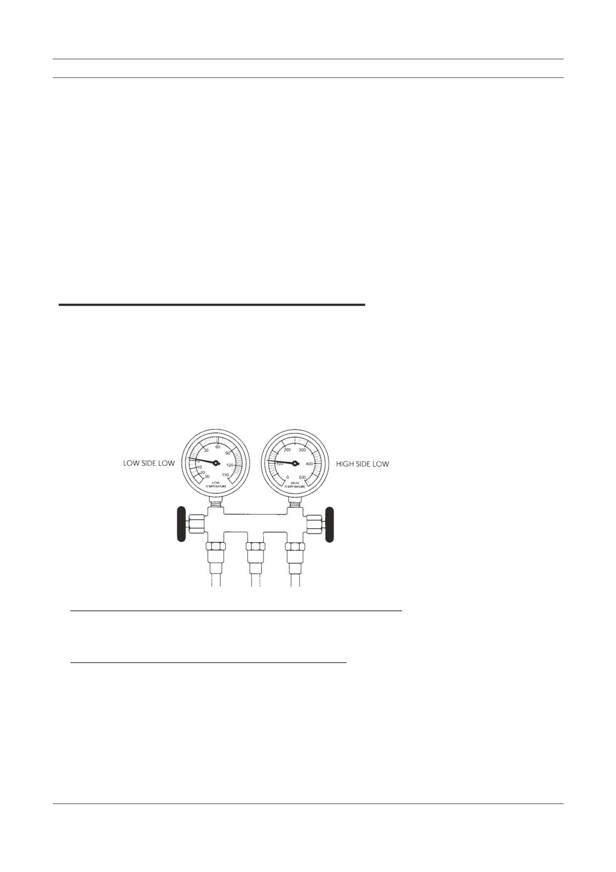
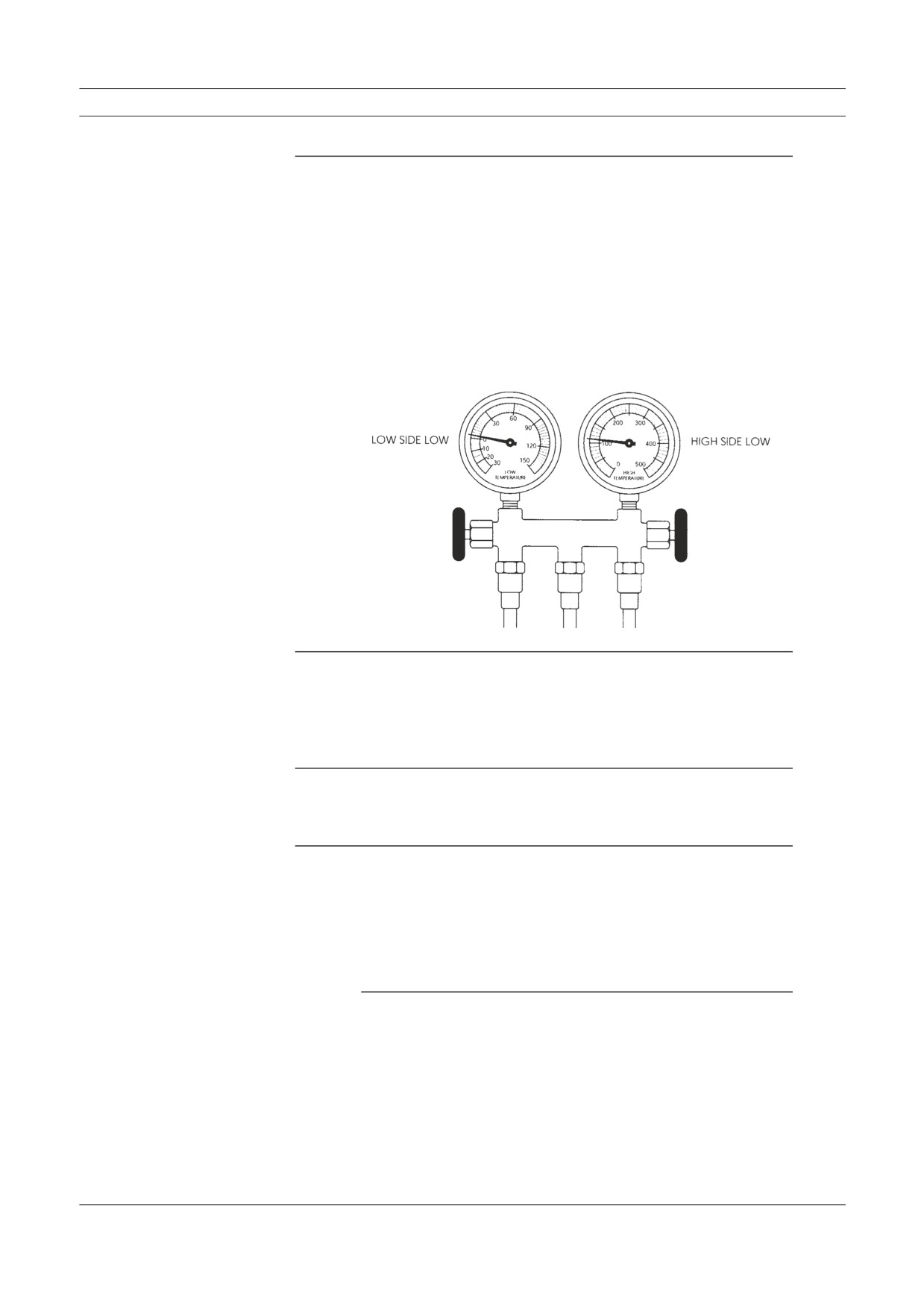
Figure 8-5
Gauge reading, low refriger-
ant charge in the system.
Tip:
You see bubbles in the sight glass. The air from vents in the
cab is only slightly cool.
Cause:
Insufficient refrigerant (charge) in the system.
Manifold Gauge Set Readings
Repair Procedure:
Check for leaks with your leak detector. If you find a leak
at a connection, tighten it then add refrigerant as necessary.
If a component or line is leaking (defective), recover all
refrigerant from the system. Replace the defective part and
then check the compressor oil level and replace missing
oil. Evacuate and recharge with refrigerant, then check AC
operation and performance.
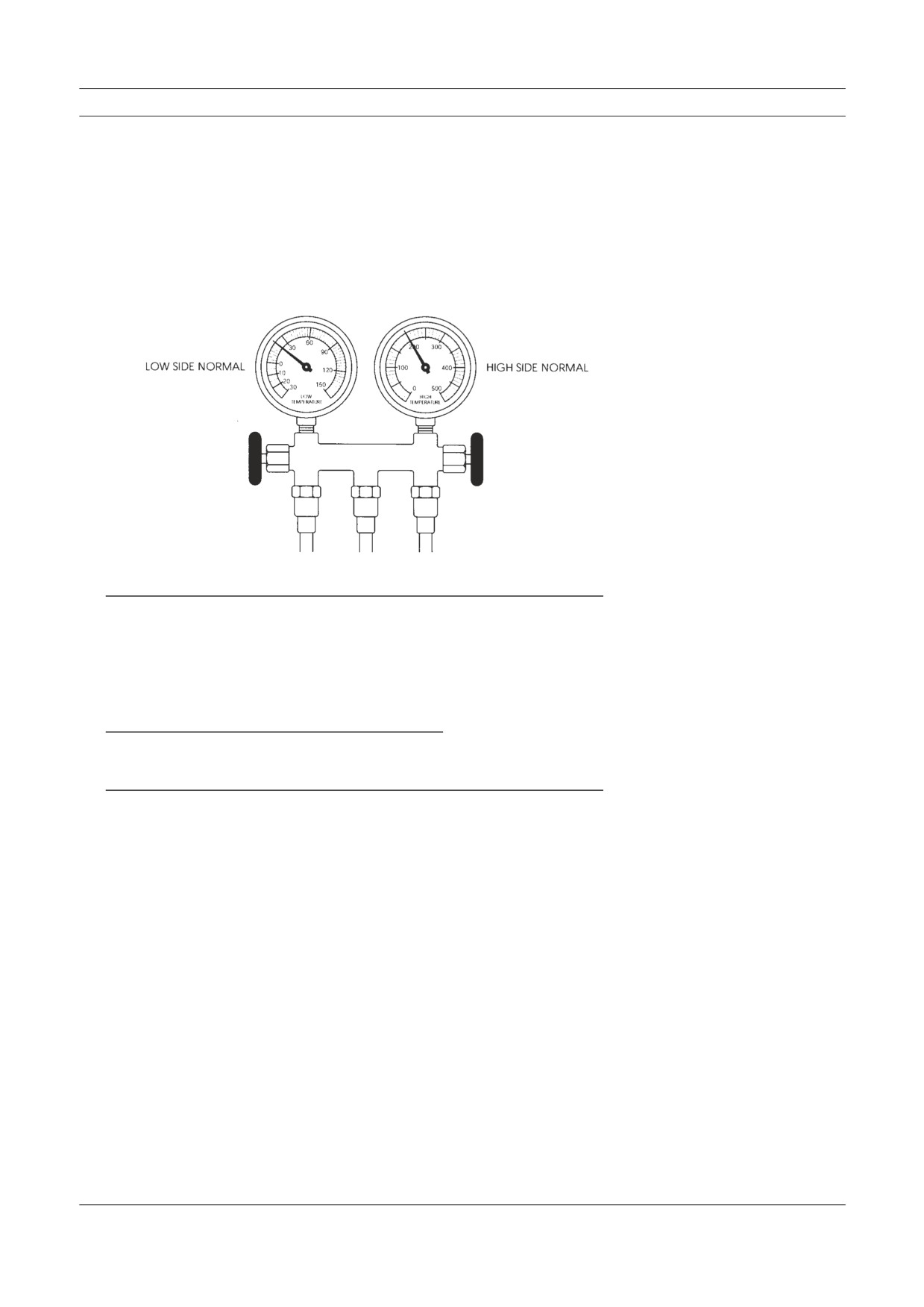
Figure 8-6
Extremely Low Refrigerant Charge in the System
Gauge reading, extremely
low refrigerant charge in
system.
Tip:
The sight glass is clear or shows oil streaks. The air from
vents in the cab seems warm. If there is a low pressure or
Trinary™ switch in the system it may have shut off the
compressor (clutch).
Cause:
Extremely low or no refrigerant in the system. There is a
leak in the system.
Repair Procedure:
Add refrigerant to the system, at least half of the normal
full charge amount. Then perform your leak test. As an al-
ternative to a refrigerant, add dry nitrogen gas to the system
and then test for leaks.
Note: It may be necessary to use a jumper wire to bypass some
types of low pressure cutout switches to operate the com-
pressor (clutch) when you add refrigerant to the system.
Troubleshooting & Service Procedures
After finding a leak, recover all refrigerant from the system
and repair the leak. Check the compressor and replace any
refrigeration oil lost due to leakage. Evacuate and recharge
the system with refrigerant, then check AC operation and
performance.
Air and/or Moisture in the System
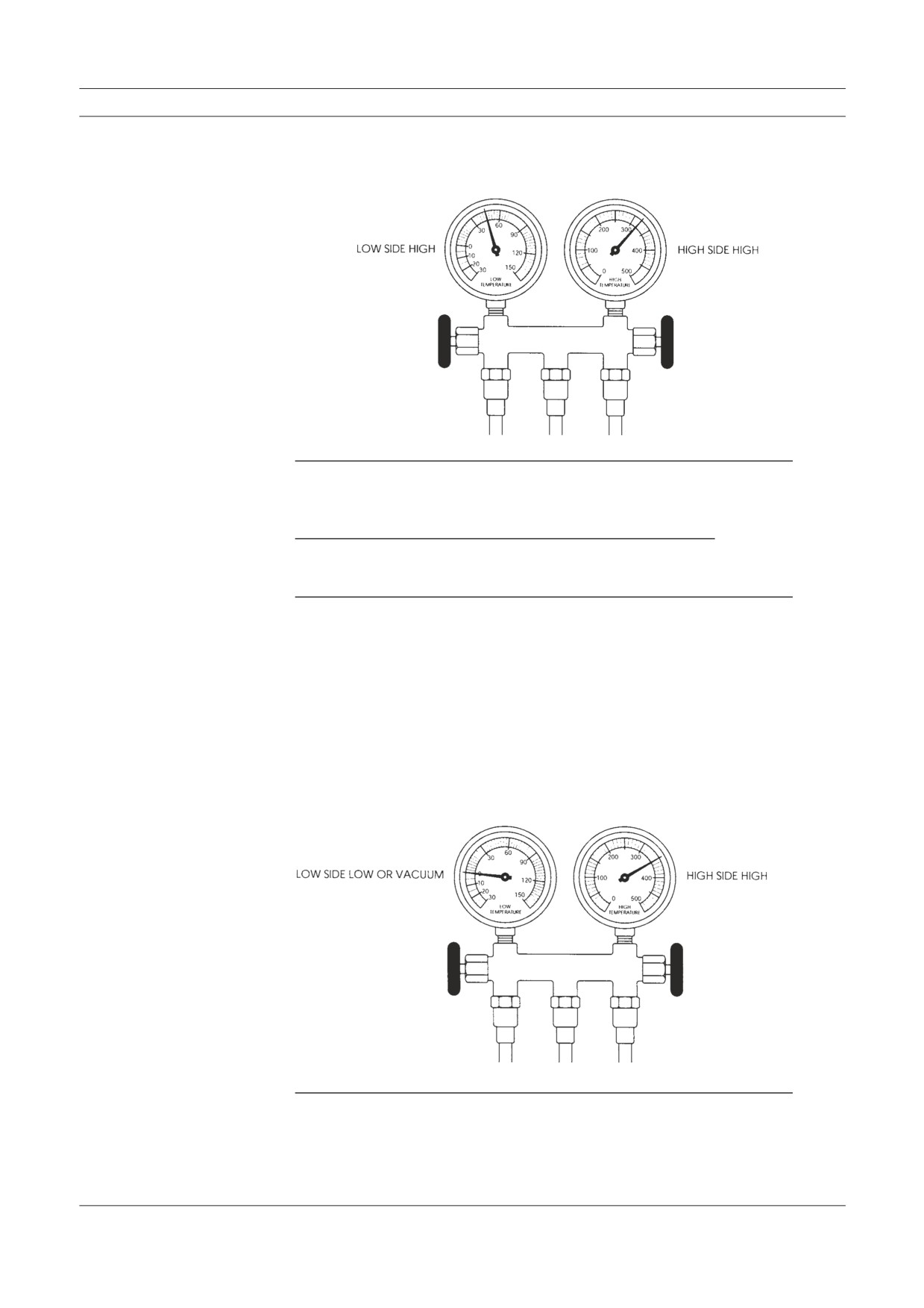
Figure 8-7
Gauge reading, air and/or
moisture in the system.
Tip:
The sight glass may be clear or show some bubbles. The
air from vents in the cab is only slightly cool. In a cycling
clutch type system with a thermostatic switch, the switch
may not cycle the clutch on and off, so the low pressure
gauge will not fluctuate.
Cause:
Air and/or moisture in the system.
RepairProcedure:
Test for leaks, especially around the compressor shaft seal
area. When the leak is found, recover refrigerant from the
system and repair the leak. Replace the receiver-drier or
accumulator because the desiccant may be saturated with
moisture (there is no way to tell). Check the compressor
and replace any refrigeration oil lost due to leakage. Evacu-
ate and recharge the system with refrigerant, then check AC
operation and performance.
Manifold Gauge Set Readings
Figure 8-8
Excessive Air and/or Moisture in the System
Gauge reading, excessive
air and/or moisture in the
system.
Tip:
There may be occasional bubbles in the sight glass. Air
from vents in the cab is only slightly cool.
Cause:
System contains excessive air and/or moisture.
Repair Procedure:
Test for leaks, recover refrigerant from the system and re-
pair the leak. Depending on the type of system, replace the
receiver-drier or accumulator. The desiccant is saturated
with moisture. Check and replace any compressor oil lost
due to leakage. Evacuate and recharge the system, then
check AC operation and performance.
Expansion Valve (TXV) Stuck Closed or Plugged
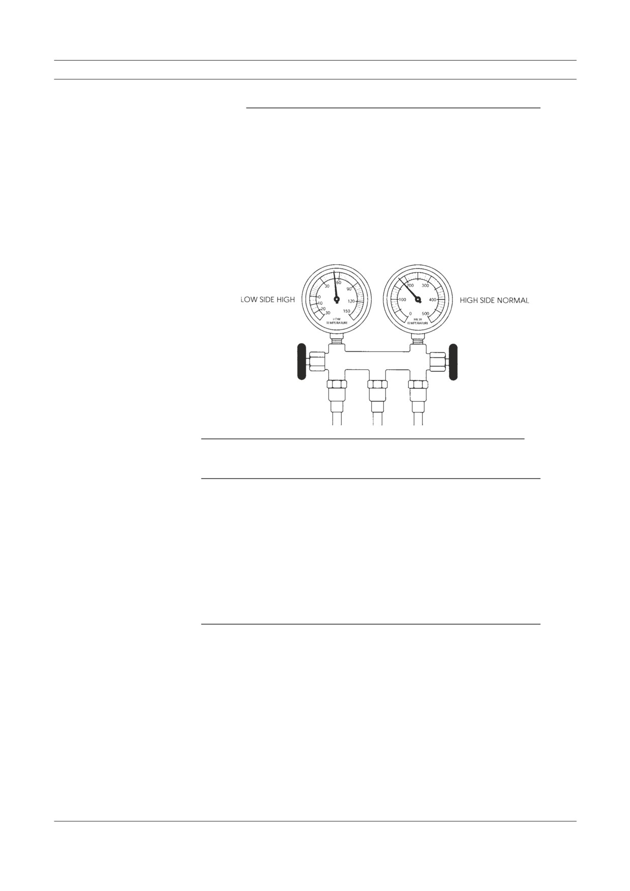
Figure 8-9
Gauge reading, expansion
valve (TXV) stuck closed.
Tip:
Air from vents in the cab is only slightly cool. The expan-
sion valve body is frosted or sweating.
Troubleshooting & Service Procedures
Cause:
An expansion valve malfunction could mean the valve is
stuck in the closed position, the filter screen is clogged
(block type expansion valves do not have filter screens),
moisture in the system has frozen at the expansion valve
orifice, or the sensing bulb is not operating. In vehicles
where the TXV and sensing bulb are accessible, perform
the following test. If not accessible, then proceed to Repair
Procedure.
Test:
1. Warm diaphragm and valve body in your hand or care-
fully with a heat gun. Activate system and watch to see
if the low pressure gauge rises.
2. Next, carefully spray a little nitrogen, or any substance
below 32 degrees Fahrenheit, on the capillary coil
(bulb) or valve diaphragm. The low side gauge needle
should drop and read at a lower (suction) pressure on the
gauge. This indicates the valve was part way open and
that your action closed it. Repeat the test, but first warm
the valve diaphragm or capillary with your hand. If the
low side gauge drops again, the valve is not stuck.
3. Clean the surfaces of the evaporator outlet and the cap-
illary coil or bulb. Make sure the coil or bulb is securely
clamped to the evaporator outlet tube and the insulation
is in place. Next proceed with recovering refrigerant
from the system.
Repair Procedure:
Inspect the expansion valve screen (except block type
valves). To do this you must recover all refrigerant from the
system. Disconnect the inlet hose fitting from the expan-
sion valve. Remove, clean and replace the screen, then re-
connect the hose. Any signs of contamination will require
flushing the system. Next, replace the receiverdrier. Then
evacuate and recharge the system with refrigerant, and
check AC operation and performance.
Manifold Gauge Set Readings
Note: If the expansion valve tests did not cause the low pressure
gauge needle to rise and drop, and if the other procedures
described did not correct the problem, the expansion
valve is defective. You must recover all refrigerant from
the system again, and replace the expansion valve and
receiver-drier. Evacuate and recharge the system with
refrigerant, then check AC operation and performance.
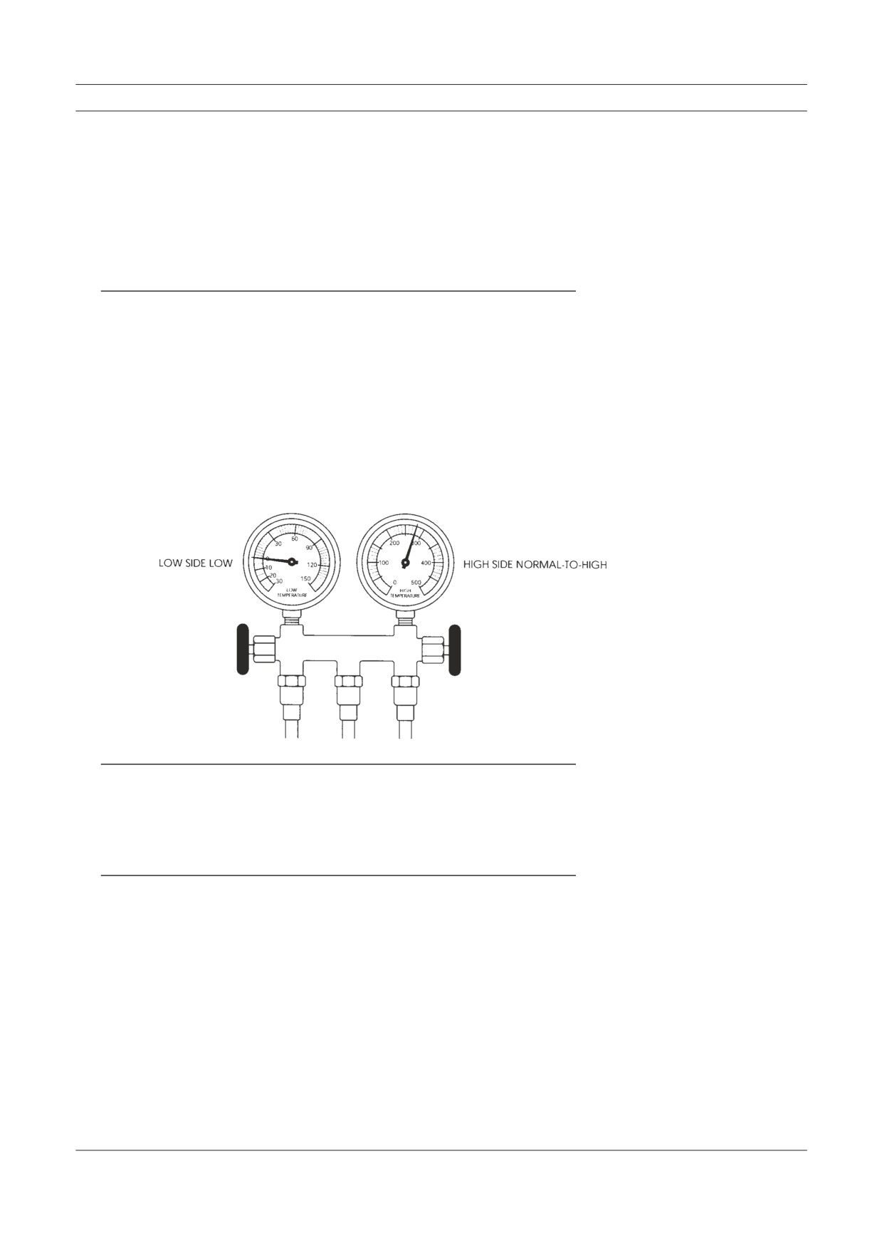
Expansion Valve (TXV) Stuck Open
Figure 8-10
Gauge reading, expansion
valve (TXV) stuck open.
Tip:
Air from vents in the cab is warm or only slightly cool.
Cause:
The expansion valve is stuck open and/or the capillary tube
(bulb) is not making proper contact with the evaporator
outlet tube. Liquid refrigerant may be flooding the evapora-
tor making it impossible for the refrigerant to vaporize and
absorb heat normally. In vehicles where the TXV and sens-
ing bulb are accessible, check the capillary tube for proper
mounting and contact with the evaporator outlet tube. Then
perform the following test. If the TXV is not accessible,
then proceed to Repair Procedure.
Test:
1. Operate the AC system on it’s coldest setting for a few
minutes. Carefully spray a little nitrogen or other cold
substance, on to the capillary tube coil (bulb) or head of
the valve.
2. The low pressure (suction) side gauge needle should
now drop on the gauge. This indicates the valve has
closed and is not stuck open. Repeat the test, but first
warm the valve diaphragm with your hand.
Troubleshooting & Service Procedures
3. If the low side gauge shows a drop again, the valve is
not stuck. Clean the surfaces of the evaporator outlet
and the capillary coil or bulb. Make sure the coil or bulb
is securely fastened to the evaporator outlet and covered
with insulation material. Operate the system and check
performance.
Repair Procedure:
If the test did not result in proper operation of the expansion
valve, the valve is defective and must be replaced. Recover
all refrigerant from the system and replace the expansion
valve and the receiver-drier. Evacuate and recharge the
system with refrigerant, then check AC operation and per-
formance.
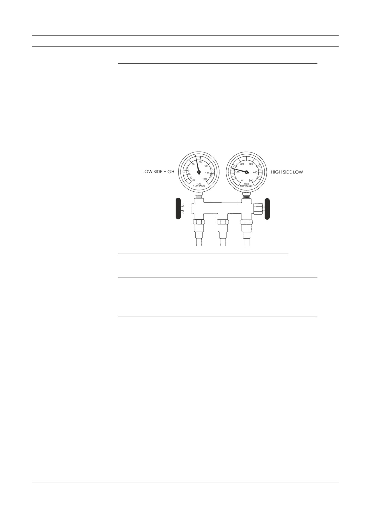
System High Pressure Side Restriction
Figure 8-11
Gauge reading, system high
pressure side restriction.
Tip:
Air from vents in the cab is only slightly cool. Look for
sweat or frost on high side hoses and tubing, and frost ap-
pearing right after the point of restriction. The hose or line
may be cool to the touch near the restriction.
Cause:
There could be a kink in a line, or other restriction in the
high side of the system.
Manifold Gauge Set Readings
Repair Procedure:
After you locate the defective component containing the
restriction, recover all of the refrigerant. Replace the de-
fective component and the receiver-drier. Evacuate and
recharge the system with refrigerant, then check AC opera-
tion and performance.
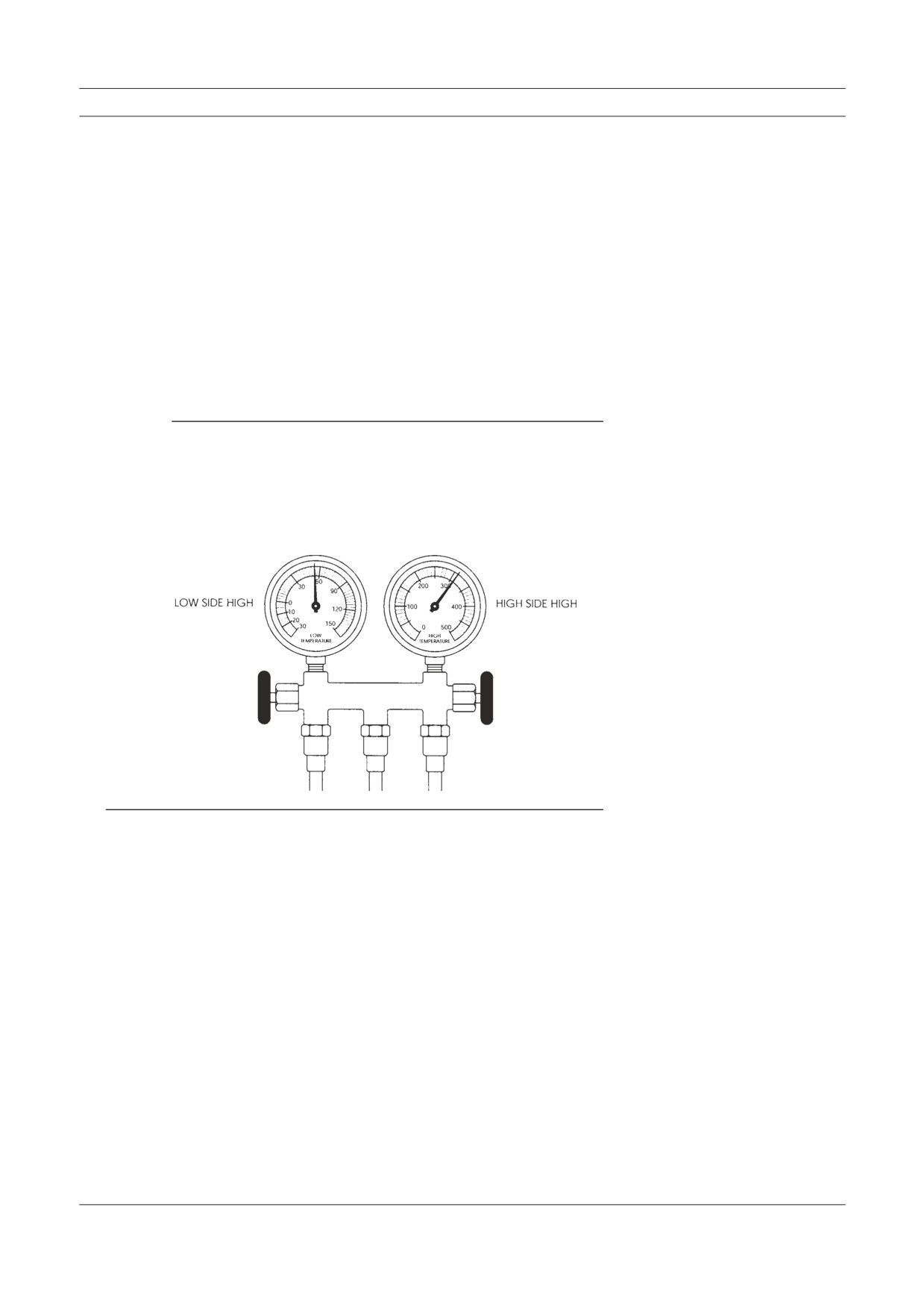
Compressor Malfunction
Figure 8-12
Gauge reading, compressor
malfunction.
Tip:
The compressor may be noisy when it operates.
Cause:
Defective reed valves or other compressor components. If
the compressor is not noisy, there may be a worn or loose
compressor clutch drive belt.
Repair Procedure:
If you find the belt worn or loose, replace or tighten it and
recheck system performance and gauge readings. To in-
spect and service the compressor, you must isolate (front
seat the stem type compressor service valves) and recover
refrigerant, or fully recover R-12 from systems containing
Schrader valves. Remove the compressor cylinder head
and check the appearance of the reed valve plate assembly.
If defective, replace the valve plate and install with new
gaskets, or replace the compressor assembly.
Troubleshooting & Service Procedures
If you find particles of desiccant in the compressor, remove
and replace it and the receiver-drier. Before doing so, back
flush other system components
(except the expansion
valve) using a flushing kit. If there are stem type valves
and you isolate the compressor, the rest of the system must
be purged of refrigerant before you can disconnect and
flush system components (Chapter 9 describes the flush-
ing procedure). After flushing, reassemble the components.
Always check the oil level in the compressor, even if you
install a new or rebuilt unit. Tighten all connections and
evacuate the system. Recharge the air conditioner with re-
frigerant and check system operation and performance.
Note: Rotary compressors have a limited oil reservoir. Extra oil
must be added for all truck installations
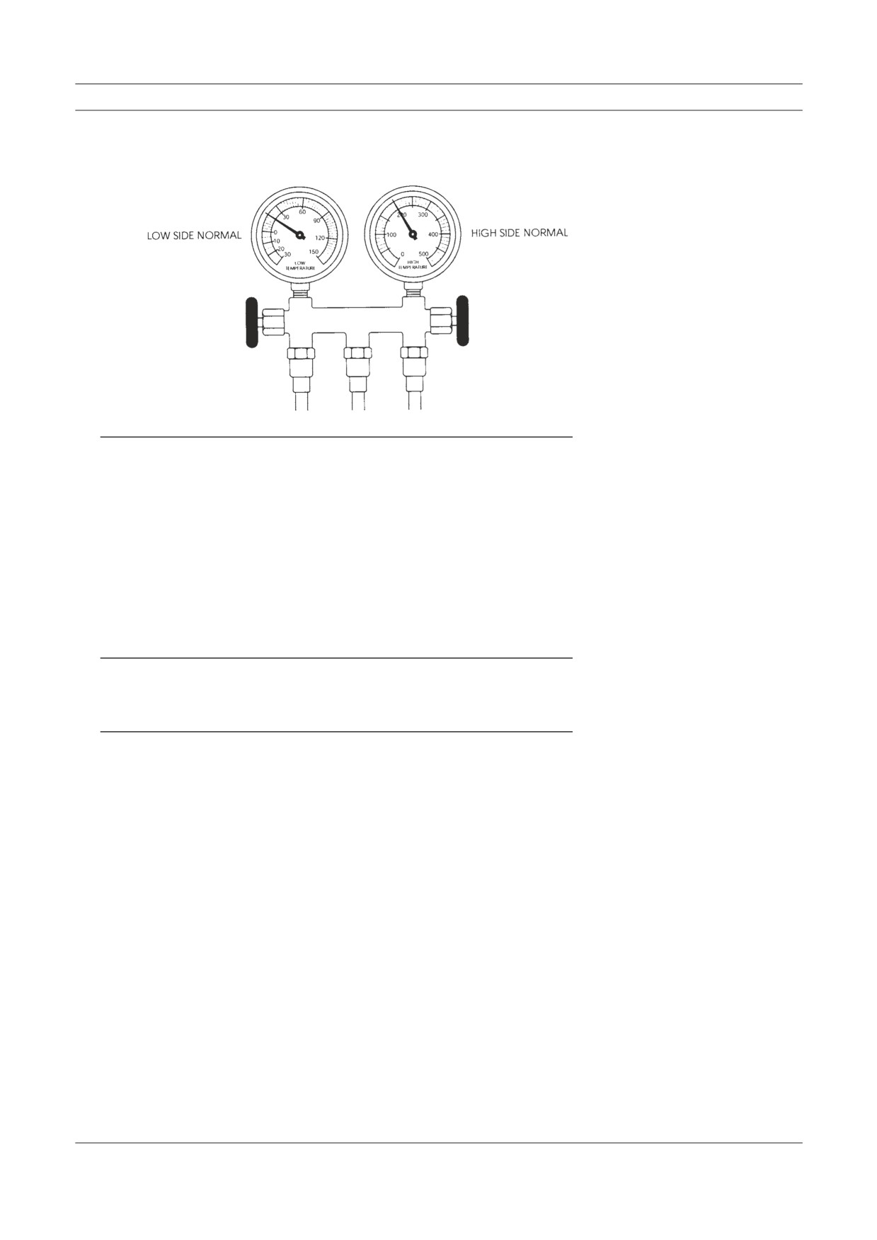
Condenser Malfunction or System Overcharge
Figure 8-13
Gauge reading, condenser
malfunction or system
overcharge.
Tip:
The air from vents in the cab may be warm. In R-12 systems
there can be bubbles in the sight glass. The high pressure
hoses and lines will be very hot. Don’t forget to check the
engine cooling system components—fan and drive belt, fan
clutch operation, and the radiator shutter.
Manifold Gauge Set Readings
Cause:
The condenser is not functioning correctly or there may
be an overcharge of refrigerant inside the system. Another
possibility is lack of (ram) air flow through the condenser
fins during testing. Engine cooling system component
malfunction can cause high pressure by blocking air flow
(radiator shutter) or not providing air flow (fan clutch) in
sufficient quantity.
Repair Procedure:
Inspect the condenser for dirt, bugs or other debris and clean
if necessary. Be sure the condenser is securely mounted and
there is adequate clearance (about 1-1/2 inches) between
it and the radiator. Check the radiator pressure cap and
cooling system, including the fan, fan clutch, drive belts
and radiator shutter assembly. Replace any defective parts
and then recheck AC system operation, gauge readings and
performance.
If the problem continues, the system may be over- charged
(have too much refrigerant inside). Recover the system
slowly until low and high pressure gauges read below nor-
mal, and bubbles appear in the sight glass. Then add refrig-
erant (charge the system) until pressures are normal and
the bubbles disappear. Add another quarter to half pound of
refrigerant and recheck AC system operation, gauge read-
ings and performance.
If the high gauge readings do not change, you should recover
all of the refrigerant and flush (it may be partially plugged)
or replace the condenser. Also replace the receiver-drier or
accumulator. Then connect the components and evacuate
the system. Recharge the air conditioner with refrigerant
and check system operation and performance.
Troubleshooting & Service Procedures
Thermostatic Switch Malfunction
Figure 8-14
Gauge reading, thermostatic
switch malfunction.
Tip:
The low side gauge needle may fluctuate in a very narrow
range compared to a normal range. The compressor clutch
may be cycling on and off more frequently than it should.
The low side gauge needle may fluctuate in an above nor-
mal range as the clutch cycles. This may be an indication
that the thermostat is set too high (someone may have at-
tempted to adjust the factory setting). A new thermostat may
have been installed incorrectly (capillary tube not inserted
between the evaporator fins in the proper position).
Cause:
The thermostatic switch is not functioning properly or at
all.
Repair Procedure:
Replace the thermostatic switch. When you remove the
old thermostat, replace it with one of the same type. (They
operate in a factory preset temperature range.) Take care in
removing and handling the thermostat and thin capillary
tube attached to it. Don’t kink or break the tube.
Position the new thermostat capillary tube at or close to
the same location and seating depth between the evaporator
coil fins as the old one. Connect the electrical leads.
Review of Frequent Problem Areas
Note: See the Thermostat section in Chapter 10. Fan clutch, ra-
diator shutter, condenser, compressor, and the newer air
and water valve control systems are covered in Chapter
10.
Review of Frequent Problem Areas
In HVAC systems a limited number of things can go wrong. Moving parts of the com-
pressor, clutch, and expansion valve or refrigerant metering device can malfunction or
break down from metal fatigue, contamination, abnormal pressure or lack of lubrica-
tion. Electrical connections may corrode, become disconnected or break. Fuses blow
from shorts or overload. Belts slip or break.
Vibration from the engine or road surface can work bolts and air or vacuum lines
loose, or rub and break or wear parts out. Motors may burn out. The inside of the
system can become contaminated from moisture, air or desiccant material breakdown.
Refrigerant may leak out of the system quickly or very slowly. Moisture in the system
can combine with refrigerant to form acid and attack (corrode) metal parts from the
inside. Moisture and refrigeration oil can combine to form sludge that may block re-
frigerant flow.
The following problems are discussed in more detail in this section:
1. Belts and Compressor Clutch
2. Condenser
3. Refrigerant Lines, Hoses, and Fittings
4. Refrigerant Metering Valves
5. Other Problems
1. Belts and Compressor Clutch
Let’s review problem areas listed at the beginning of Chapter 7. The most fre-
quent repairs are replacing belts and servicing or replacing the compressor or
clutch. Heavy duty vehicle operation puts a lot of stress on these parts. There are
several main reasons.
There is often continuous operation for long periods of time. There may be
frequent sudden RPM variations when shifting gears up or down. For this reason
the AC clutches used in heavy duty systems usually have double row ball bear-
ings. Vibration and road shock contribute to loose or broken mounting brackets,
electrical connections and fittings. Belts, bearings and compressor reed valves
wear out.
Various compressor clutch cutout switches are used because the AC designers
know about compressor operating conditions. System leaks, high operating pres-
sures, malfunctioning engine cooling system components—all cause compressor
problems and failures. When refrigerant and refrigeration oil leaks out of a sys-
tem or there is contamination blocking oil flow, the compressor will be starved
for oil and seize.
Troubleshooting & Service Procedures
2. Condenser
Condensers get dirty and the dirt reduces heat movement by insulating the con-
denser. The fittings come loose or break from stress if the condenser or connecting
hoses are not secured properly to keep the effects of vibration at a minimum.
Heat transfer efficiency and pressure in the condenser are affected by the
amount of outside air flowing through condenser fins. A lack of air flow can mean
the refrigerant doesn’t give up enough heat energy to the outside air (it doesn’t
change state). The refrigerant arrives at the evaporator as a gas and can’t pick up
any heat energy from cab air. In the cab, air from the vents is only slightly cool
or warm.
One possible cause of condenser malfunction could be the engine cooling sys-
tem. This is why fan clutches and radiator shutters are often controlled or over-
ridden by AC switch function. In fact, we can add fan clutch, radiator shutters and
also fan motors to condenser problems. If they don’t function to allow sufficient
air through the condenser, pressure inside the system may become dangerously
high. A lack of air through the condenser fins can raise high side pressure and
blow out the weakest point in a system, or damage the compressor.
3. Refrigerant Lines, Hoses and Fittings
Problems with these parts may be caused by normal deterioration, vibration dam-
age, lack of maintenance or human error (improper installation or replacement).
All rubber parts are attacked by ozone (oxygen) in the air. Rubber parts break
down slowly and become more vulnerable to the effects of vibration with the
passage of time.
Heavy duty vehicle vibration causes stress on all lines, fittings and connections.
Regular maintenance includes checking and tightening any suspect line, or hose
retainers, or grommet position where the grommet is protecting a line or hose
from abrasion. Any insulating material wrapped around hoses must be in place
and securely fastened.
4. Refrigerant Metering Valves
When you consider valve problems there are obvious differences in valve con-
struction and what can go wrong. If a valve is clogged with sludge or other
obstruction, the result is a valve problem but the cause is contamination in the
system. Valves get stuck open or closed, although most often closed when the
gas charge is lost from the diaphragm housing in a traditional TXV. The capillary
tube can vibrate loose from the evaporator outlet tube. The capillary can break
and the small quantity of temperature sensitive gas can escape. The diagnosis of
a valve as defective calls for replacement.
5. Other Problems—Leaks, Moisture, and Adding
Refrigerant
Before any refrigerant was put inside the AC system, someone used a vacuum
pump to evacuate any air and moisture. Vacuum is really a force pulling against
all hoses, fittings and components from the inside. When the system is charged
with refrigerant, the pressure goes from minus (a vacuum) to plus pressure inside
the hoses and all components. The refrigerant and refrigeration oil are trying to
escape from the system at all times.
Conclusion
Technicians frequently add refrigerant to a system, replacing refrigerant seep-
age through system connections or fittings. If the system has been maintained
regularly (every three to six months), adding a small amount of refrigerant may
result in normal system function. However, the best procedure is to check all
connections and look for, find and repair any leaks before adding refrigerant.
When your leak detector indicates the presence of a leak, you can’t tell how
long the system has been leaking. Finding one leak doesn’t mean there are not
others. Until you have some AC system work experience, it will be hard to guess
how much refrigerant may have leaked. If you have to top a system off with a half
pound of refrigerant or more, adding refrigerant is not the answer.
Find the leak. Recover all of the refrigerant and repair the system. The mois-
ture absorbing capacity of any desiccant material is limited and cannot be mea-
sured. For that reason, replace the receiver-drier or accumulator. Then evacuate
the system for an hour and recharge with refrigerant.
When a compressor shaft seal has leaked oil and the refrigerant charge is a little
low, the shaft seal may have leaked because the air conditioner was not used. The
seal can get a little out of round from the weight of the crankshaft and leak above
the shaft. Running the compressor may cause the seal to swell and close up the
leak. The shaft rotation exerts force all around the seal and puts life back into it.
To prevent this from happening, manufacturers recommend regular AC system
operation a minimum of every couple of weeks even in cool weather.
Keep in mind that the compressor can cause a vacuum inside the system if there
is a restriction in the system. That means it can suck air and moisture inside under
some conditions. It will pull these contaminants in through the same space where
refrigerant and refrigerant oil has leaked out.
Conclusion
What could the air conditioning problem and it’s cause have been at the beginning of
this chapter? The operator was in a hurry, but you were able to start your troubleshoot-
ing with the answers he gave you. Problems your inspection may have turned up are
a very low refrigerant charge, a contaminated system or defective compressor. Those
are not quick fix jobs.
On the other hand, you might have found enough debris on the condenser fin sur-
face to boost high side pressures to an abnormal level during the hottest part of the day.
So the Trinary™ or high pressure switch would cut out from high pressure—but reset
itself. You cleaned the condenser, added a half pound of refrigerant and AC system
pressures and function returned to normal. Service and repair took a half hour. But
there was no way to tell without using your knowledge and experience. By now you
are pretty familiar with AC system problems, the reasons for some of them, trouble-
shooting and repair. In Chapter 9 we will describe complete system purging, evacua-
tion, flushing and recharging.
6
LEVER SWITCH PATTERN SWITCHING METHOD
LEVER SWITCH PATTERN SWITCHING METHOD
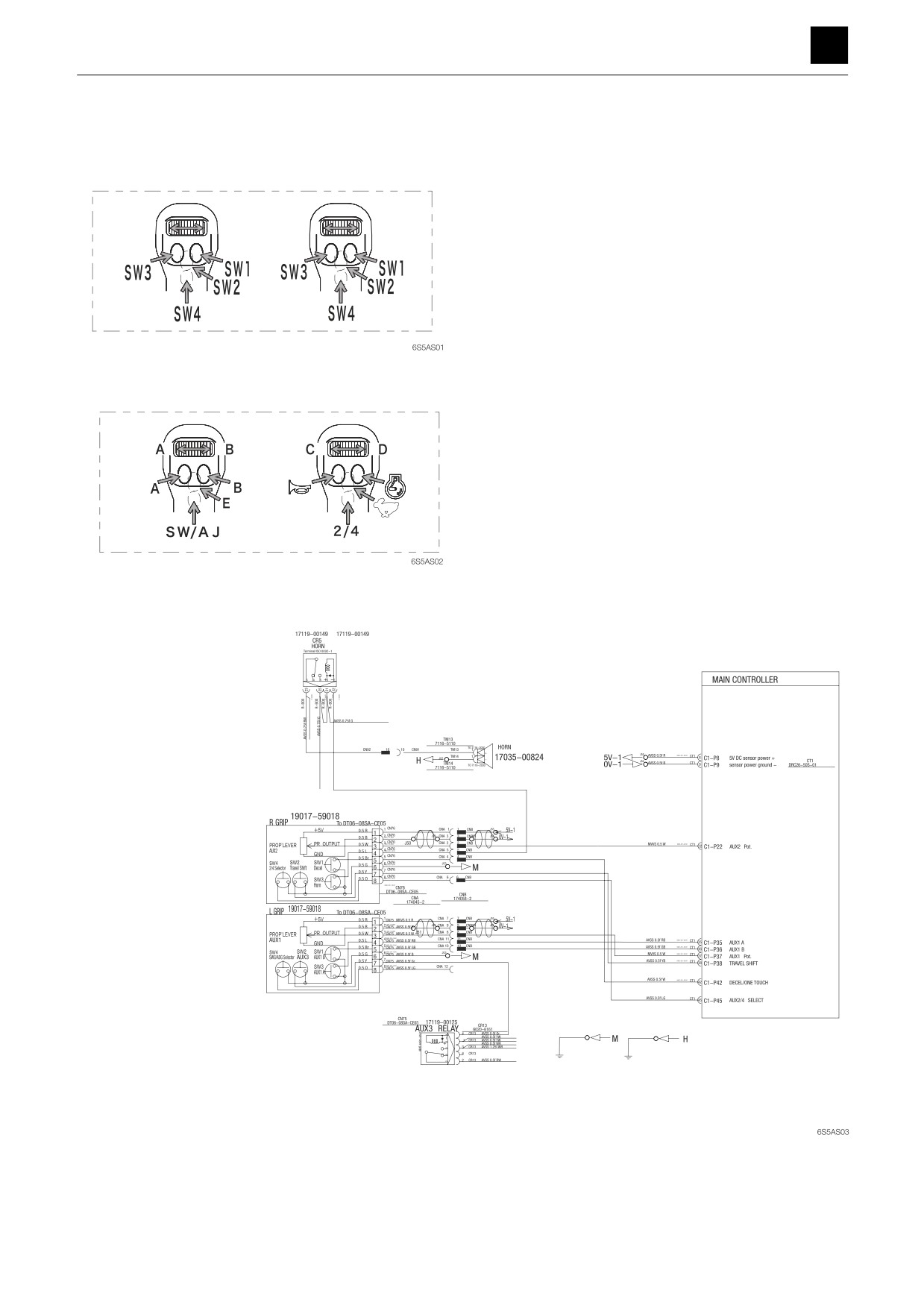
Standard pattern
1
LEVER SWITCH PATTERN SWITCHING METHOD
6S5AS00
6
LEVER SWITCH PATTERN SWITCHING METHOD
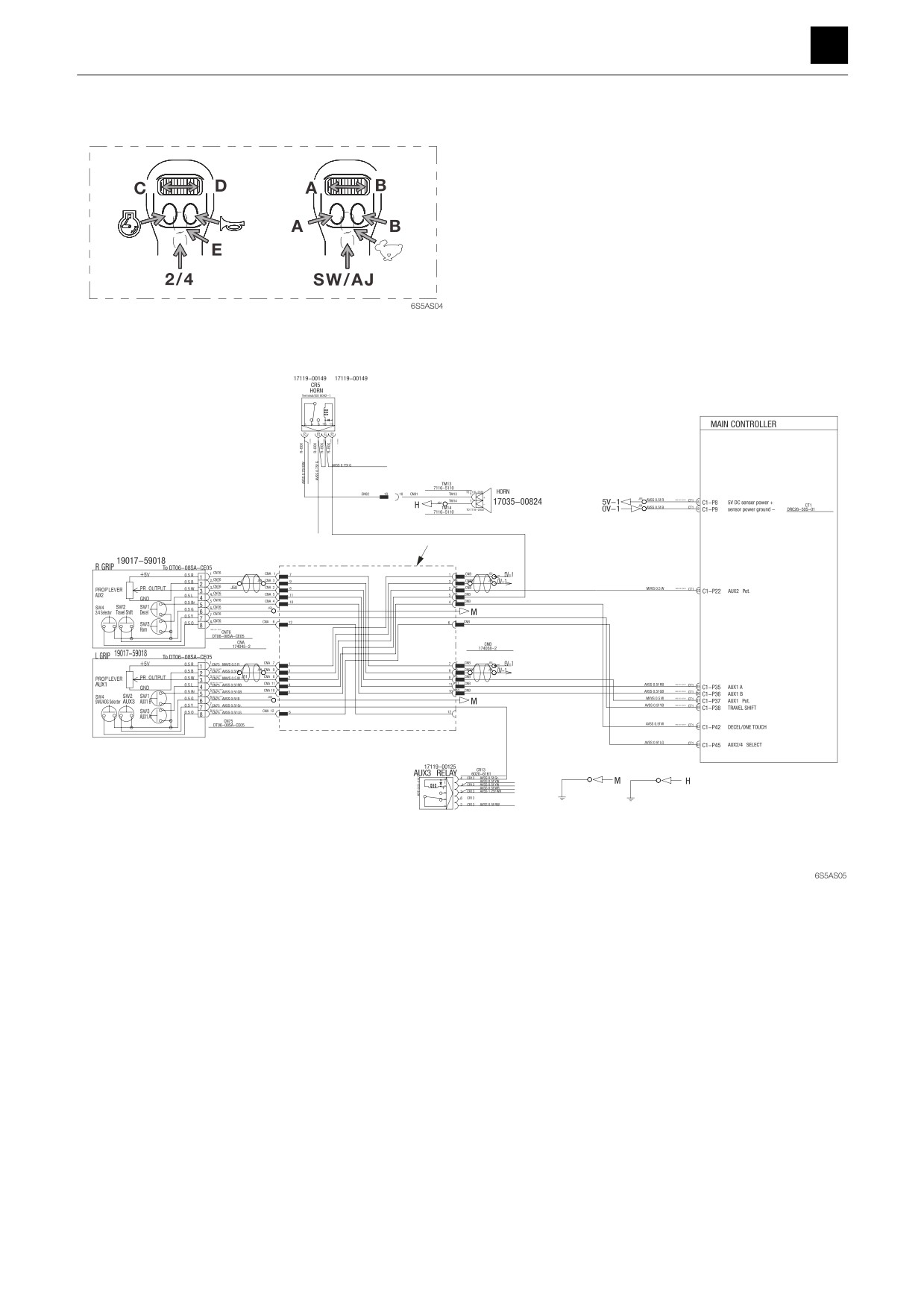
Case 1: Reversing the 1st auxiliary line piping and 2nd auxiliary line piping
A
2
LEVER SWITCH PATTERN SWITCHING METHOD
6S5AS00
6
LEVER SWITCH PATTERN SWITCHING METHOD
WARNING
1
• Make sure to change the decal sticker after changing
the switch pattern.
A
• Slowly run the machine to check to ensure that the new
decal sticker matches machine operation.
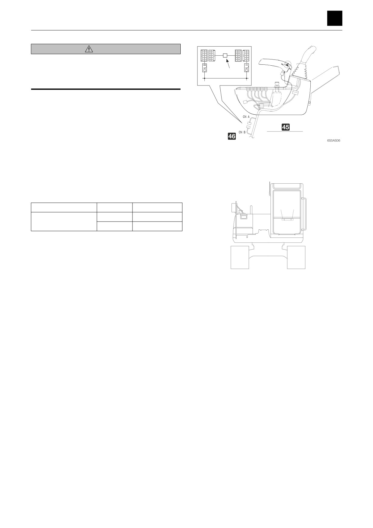
1. Disconnect the connector CAN and connector CNB
of the body harness on the back of the right control
box.
2. Attach the harness (A) between the disconnected
connector CAN and connector CNB.
• Harness (A) is included in the OPERATING LE-
I Details on inside of right control box
VER SWITCH KIT (Part No. 05701-00006).
J Operating pattern switch connector
3. Replace the decal sticker in the specified location
with the switch pattern written on it to reflect the
change.
Details of Change
Location
Part number
2
1
1
05693-66541
Harness (A) attached
2
05693-66542
• The part no. is printed on the lower right on the de-
cal.
• The decal is included in the OPERATING LEVER
SWITCH KIT (Part No. 05701-00006).
6S5AS07
3
LEVER SWITCH PATTERN SWITCHING METHOD
6S5AS00
6
LEVER SWITCH PATTERN SWITCHING METHOD
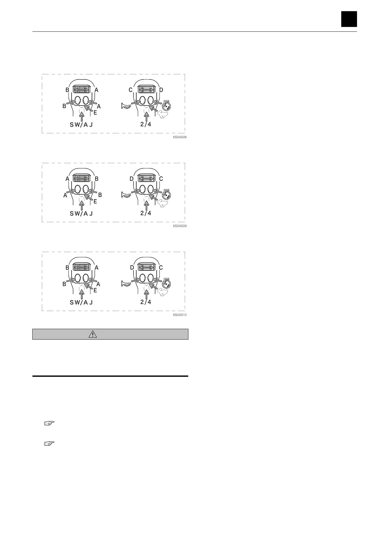
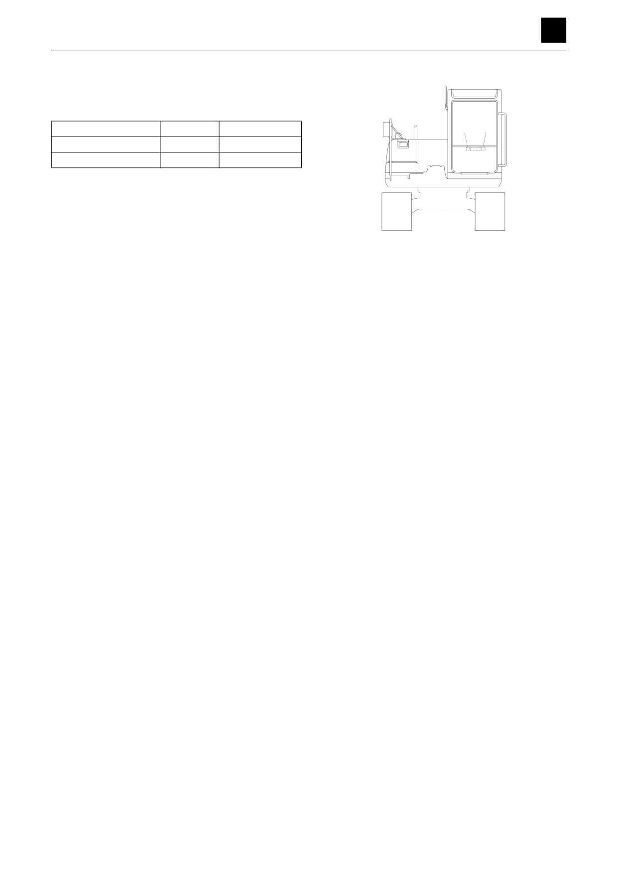
Case 2: Reversing A and B around or C and D around
Reversing A and B
Reversing C and D
Reversing both A and B around and C and D around
WARNING
• Make sure to change the decal sticker after changing
the switch pattern.
• Slowly run the machine to check to ensure that the new
decal sticker matches machine operation.
1. Connect the maintenance tool to the machine, and
run the TB1140 maintenance software.
Connecting the maintenance tool and starting up the
software
“6 Maintenance Software Manual”
2. Change the switch pattern.
“6 Maintenance Software Manual”
4
LEVER SWITCH PATTERN SWITCHING METHOD
6S5AS00
6
LEVER SWITCH PATTERN SWITCHING METHOD
3. Replace the decal sticker in the specified location
with the switch pattern written on it to reflect the
change.
Details of Change
Location
Part number
2
1
A and B reversed
1
05693-66547
C and D reversed
2
05693-66548
• The part no. is printed on the lower right on the de-
cal.
• The decal is included in the OPERATING LEVER
SWITCH KIT (Part No. 05701-00006).
6S5AS07
5
LEVER SWITCH PATTERN SWITCHING METHOD
6S5AS00
6
LEVER SWITCH PATTERN SWITCHING METHOD
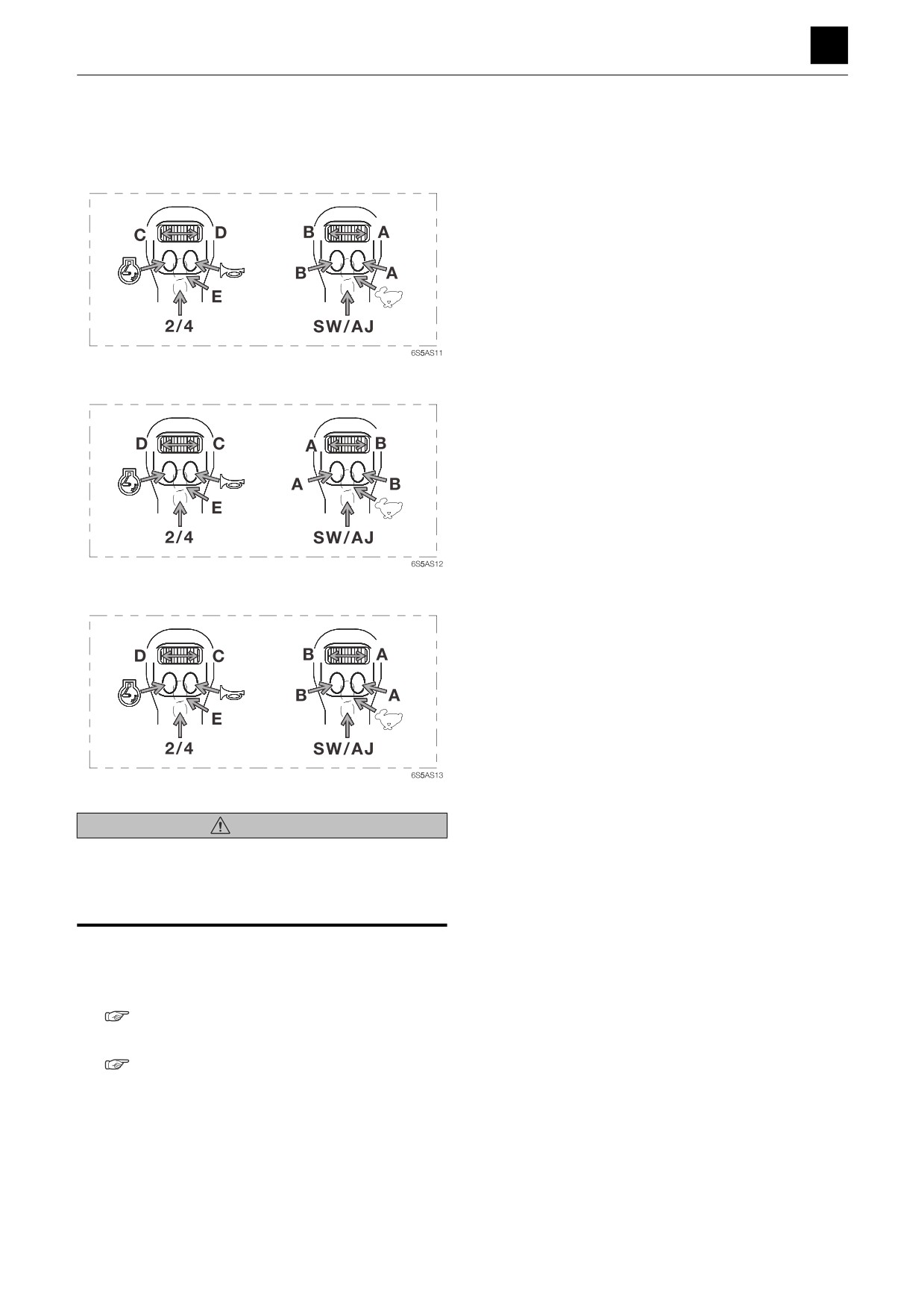
Case 3: Reversing the 1st auxiliary line piping and 2nd auxiliary line piping and reversing either
A and B around or C and D around
Reversing A and B
Reversing C and D
Reversing both A and B around and C and D around
WARNING
• Make sure to change the decal sticker after changing
the switch pattern.
• Slowly run the machine to check to ensure that the new
decal sticker matches machine operation.
1. Reverse the 1st auxiliary line piping and 2nd auxiliary
line piping.
Reversing the lines
“Case 1”
2. Reverse A and B around or C and D around.
“Case 2”
6
LEVER SWITCH PATTERN SWITCHING METHOD
6S5AS00
6
LEVER SWITCH PATTERN SWITCHING METHOD
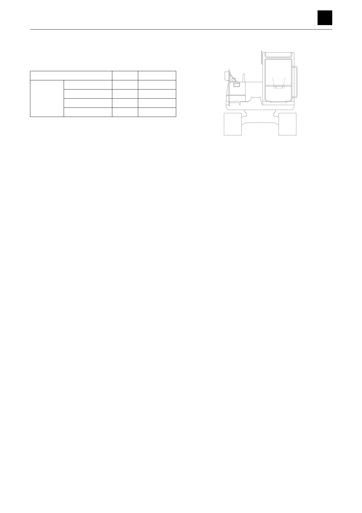
3. Replace the decal sticker in the specified location
with the switch pattern written on it to reflect the
change.
Details of Change
Location
Part number
2
1
A and B left as is
2
05693-66542
Harness (A)
A and B reversed
2
05693-66544
attached
C and D left as is
1
05693-66541
C and D reversed
1
05693-66543
• The part no. is printed on the lower right on the de-
cal.
6S5AS07
• The decal is included in the OPERATING LEVER
SWITCH KIT (Part No. 05701-00006).
7
LEVER SWITCH PATTERN SWITCHING METHOD
6S5AS00