Takeuchi Hydraulic excavator TB1140 (Serial No. 514400002~). Operator's Manual - page 12

TROUBLESHOOTING
5
CYLINDERS
CYLINDERS
“4. Disassembly and assembly, Cylinders”
Symptoms
Major causes
Remedies
Oil is leaking from the pis-
•
Foreign matter is trapped in the inside
•
Remove the foreign matter.
ton rod sliding surface (oil
diameter of the rod packing or dust
forms a ring on the piston
seal.
rod, which becomes larg-
•
Scratching or abnormality of the inter-
•
Replace the faulty part(s).
er and starts dripping)
nal lip surface of the rod packing or
dust seal.
•
Scratching on the sliding surface of the
•
Smooth the sliding surface with an oilstone
piston rod.
(1.6 S or less).
•
If the leak persists after smoothing the slid-
ing surface, replace the rod packing and
other seals.
•
If the leak persists after replacing the seals,
replace the piston rod.
•
Peeling of the hard chromium plated
•
Re-plate the hard chromium plating.
surface.
Oil leaking around the rod
•
O-ring is damaged.
•
Replace the faulty part(s).
cover.
•
Backup ring is damaged.
•
Replace the faulty part(s).
Oil leaking from welded
•
Tube welding is damaged.
•
Replace the faulty part(s).
joint.
Spontaneous cylinder
•
Foreign matter is trapped in the wear
•
Remove the foreign matter.
drop (“Spontaneous
ring sliding surface.
drop” is defined as 0.5
•
Scratching or abnormality of the wear
•
Replace the faulty part(s).
mm or greater piston
ring sliding surface.
movement in 10 minutes
•
Scratching on the piston packing slid-
•
Replace the faulty part(s).
when a static load is exert-
ing surface.
ed on the rod. The static
•
O-ring is damaged.
•
Replace the faulty part(s).
load is determined by
multiplying the maximum
operating pressure by the
cylinder area.)
1
CYLINDERS
5L0AQ00
TROUBLESHOOTING
TRAVEL MOTOR 5
TRAVEL MOTOR
“4. Disassembly and assembly, Travel motor”
Hydraulic motor
Symptoms
Major causes
Remedies
Motor fails to start
•
All the devices other than the motor and
•
Check whether the specified pressure is
the reduction gears are not working
generated in the inlet port, and then check
correctly.
and repair each device.
•
Pressure oil is not flowing properly due
•
Replace the abnormally worn out part(s).
to abnormal wear of the motor’s sliding
part.
•
Motor is faulty, as its main components
•
Replace the damaged part(s).
are damaged.
Rated speed cannot be
•
Specified volume of flow is not supplied
•
Check whether the specified pressure is
obtained
to the motor due to the faulty oil pump.
generated in the inlet port, and then check
and repair each device.
•
Motor volume efficiency becomes low.
•
Check if there is abnormal wear on the slid-
ing part; if so, repair or replace it.
Rotational fluctuations are
•
High-pressure oil is leaking from the
•
Replace the abnormally worn part, if any.
large
drain port, because the motor’s sliding
part is worn out.
•
Bearing is worn out.
•
Replace the abnormally worn part, if any.
Oil leak
•
Oil leak due to O-ring breakage.
•
Replace the oil seal and O-ring.
•
Oil seal is broken by the internal pres-
•
Repair the motor and replace the oil seal.
sure generated in the motor case due
to the abnormal wear of the sliding part
of the motor.
•
Pressure increase in the drain piping
•
Clean the clogging in the drain piping and
caused by the clogging of foreign mat-
replace the oil seal.
ter resulted in breakage of oil seal.
2nd-speed control
Symptoms
Major causes
Remedies
Straight-ahead traveling
Spool cannot be switched.
level is low, switching to
• Foreign matter is caught.
•
Remove foreign matter and correct or re-
2nd-speed travel is dis-
place the faulty part(s).
abled
• Spring is missing.
•
Install the spring.
• Spring is damaged.
•
Replace the spring.
• Oil leak due to the abnormal wear of the
•
Replace the 2nd-speed control piston.
2nd-speed control piston.
• 2nd-speed control piston is missing.
•
Install the 2nd-speed control piston.
• Ball is abnormally worn out.
•
Replace the ball.
1
TRAVEL MOTOR
5M0AQ00

TROUBLESHOOTING
TRAVEL MOTOR 5
Parking brake
Symptoms
Major causes
Remedies
Braking force is insuffi-
• Disc surface is faulty.
• Repair or replace
cient or not evenly applied
• Spring is damaged.
• Replace the spring.
• Bolt for manual releasing is being fitted.
• Remove the bolt for manual release, and fit
the plug.
Abnormal heat generation
• Release of braking is faulty.
due to brake drag
• Oil leak due to O-ring breakage.
• Replace the O-ring.
• Orifice is clogged.
• Clean the orifice.
• Pilot pressure for the releasing is not
• Check whether the specified pressure is
working.
generated in the pilot port, and then check
and repair each device.
2
TRAVEL MOTOR
5M0AQ00
TROUBLESHOOTING
SLEW MOTOR 5
SLEW MOTOR
Abnormal noise or heat indicates that a defect has occurred. If such a symptom occurs, immediately stop the machine
and locate the position of the fault.
The table below shows the causes of problems that can occur in the hydraulic circuits and the appropriate remedies.
Hydraulic motor, brake valve
Symptoms
Description/location
Major causes
Remedies
Motor fails to start.
•
No pressure at the motor inlet
•
Relief valve set pressure is too
•
Set correctly.
port.
low.
•
Faulty pump.
•
Repair or replace.
•
Faulty control valve.
•
Repair or replace.
•
Pressure is applied at the motor
•
Excessive load.
•
Reduce the load.
inlet port.
•
Faulty hydraulic motor.
•
Repair or replace.
•
Faulty reduction gears.
•
Replace the reduc-
tion gears.
Motor speed does
•
Inadequate pump discharge vol-
•
Excessive pump drain volume.
•
Repair or replace
not increase.
ume.
the pump.
•
Problem with motor function.
•
Poor hydraulic motor volumetric
•
Replace the motor.
efficiency.
Oil leaks.
•
Leaking from oil seal.
•
Damage to the seal lip.
•
Replace the oil
seal.
•
Leaking from mating surface.
•
Loose bolts.
•
Retighten the bolts.
•
Defective O-ring.
•
Replace
•
Scratches on mating surface.
•
Repair surface with
oilstone or sandpa-
per.
Abnormal noise
•
Noise from piping.
•
Pipes are inadequately support-
•
Clamp the pipes.
from motor.
ed.
Temperature in-
•
Lubricating oil.
•
Low oil level.
•
Add oil.
creases in the re-
•
Hydraulic oil in the casing.
•
Replace the reduc-
duction gear cas-
tion gears.
ing.
•
Gear unit.
•
Damaged bearing.
•
Replace the reduc-
tion gears.
•
Damaged gear surfaces.
•
Replace the reduc-
tion gears.
1
SLEW MOTOR
5N0AQ00

TROUBLESHOOTING
SLEW MOTOR 5
Parking brake
Symptoms
Major causes
Remedies
Brake cannot be re-
• Release pressure PB and valve switch-
•
Set the release pressure PB and signal
leased.
ing signal pressure SH are not generat-
pressure SH to the prescribed pressure.
Low brake force.
ed. Or, low supply pressure.
Brake slips, generating
• Valve does not operate due to high
•
Check the drain circuit for clogging, and re-
noise and heat.
drain pressure.
pair if necessary. If drain from the motor is
excessive, check and repair the motor.
Timing valve does not switch.
• Scratched or worn sliding parts.
•
Repair or replace the sliding parts.
• Trapped foreign matter.
•
Remove foreign matter and repair or re-
place the faulty part(s).
• Damaged spring.
•
Replace
Brake piston does not operate.
• Damaged O-ring.
•
Replace
• Scratched or worn sliding parts.
•
Repair or replace the sliding parts.
• Trapped foreign matter.
•
Remove foreign matter and repair or re-
place the faulty part(s).
• Worn friction material.
•
Replace
• Damaged spring.
•
Replace
2
SLEW MOTOR
5N0AQ00
6
OTHER
Maintenance software manual
Air conditioner
Lever switch pattern switching method
Hydraulic system schematic
6
MAINTENANCE SOFTWARE MANUAL
APPLICABLE MODELS: TB1140
APPLICABLE SERIAL NO.:
514400001~
1
6S1AS01
CONTENTS 6
CONTENTS
1. Outline
2. Connection methods
2-1. Items needed
2-2. Installation of the PLUS+1 GUIDE Service Tool
2-3. Installation of the Maintenance Tool driver
2-4. Connection to the machine and startup of the Maintenance Software
3. Description of functions
3-1. Main screen
3-2. Machine status
Inputs
Outputs
Feedback
CAN
Error Code1
Error Code HVAC
Status of other parts and sections
3-3. Engine status
Engine_Status
DPF_Status
3-4. AUX1 Settings
AUX1 status
Grip_Settings
Current_Settings
3-5. AUX2 Setting
3-6. Others
Option
Dev Control mode
Grip pattern
Misc
Liftalarm
2
CONTENTS
6S1AS01
6
1. OUTLINE
1. OUTLINE
This software program is designed for use in mainte-
nance procedures. You can perform the various types of
maintenance listed below using this software and a main-
tenance cable.
• Machine status
This function can be used to check the input/output con-
ditions for the controller, the actual current output by the
auxiliary line piping, the status of CAN communications,
the malfunction error codes displayed, and the status of
other machine parts and sections.
• Engine status
This function can be used to check the status conditions
of the engine and diesel particulate filter (DPF).
• AUX1 Settings
This function can be used to adjust the flow rates for the
flow select modes I, II, and III; adjust the operating sen-
sitivity of the sliding switches; and set the output current
setting value.
• AUX2 Settings
This function can be used to adjust the flow rates for the
2nd/4th auxiliary line piping, adjust the operating sensi-
tivity of the sliding switches, and set the output current
setting value.
• Other
This function can be used to set options, operate the die-
sel particulate defuser (DPD), set the lift alarm, change
the switch operation pattern, and perform other similar
tasks.
3
1. OUTLINE
6S1AS01
6
2. CONNECTION METHODS
2. CONNECTION METHODS
• To use the Maintenance Software program, complete
Steps 2-2 to 2-4 in sequential order.
• Screens shown and installation instructions may vary
depending on the operating system used due to differ-
ences in the language settings and OS used among
other factors. Refer to the instruction manual for the
computer you are using for additional information
should you have questions or need computer-specific
assistance.
• Note that the PLUS+1 GUIDE Service Tool installation
method may change without prior notice. Contact
Takeuchi Manufacturing should any questions arise
regarding installation.
2-1. Items needed
1. Computer
2. CD for installation (Product no.: 05701-00005)
3. Maintenance Tool (Product no. 17301-41810)
4. Cable assembly (Product no.: 17301-41820)
4
2. CONNECTION METHODS
6S1AS01
6
2. CONNECTION METHODS
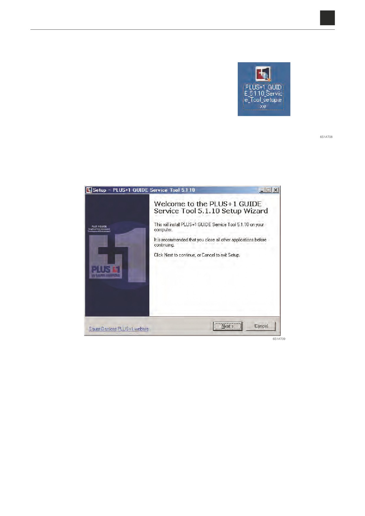
2-2. Installation of the PLUS+1 GUIDE Service Tool
a. Start up the setup.exe file.ʢCD for installationʣ
• You must have administrator privileges to start
up the Setup Tool. Contact your system admin-
istrator for assistance if you are unable to exe-
cute the file.
b. Once you have executed the setup.exe file, the screen shown below will appear. Click the [Next] on the screen
to proceed.
5
2. CONNECTION METHODS
6S1AS01
6
2. CONNECTION METHODS
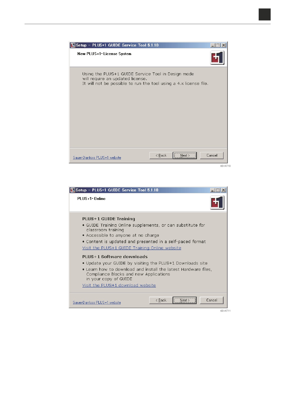
c. Click [Next] to proceed.
d. Click [Next] to proceed.
6
2. CONNECTION METHODS
6S1AS01
6
2. CONNECTION METHODS
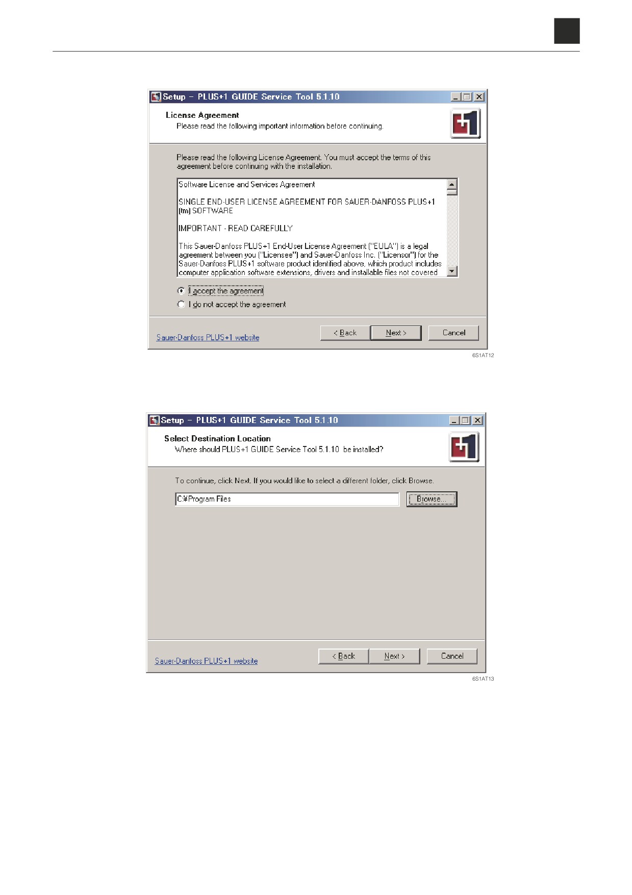
e. Select “I accept the agreement” and then click [Next] to confirm and proceed.
f. Specify the folder for installation (continue as is unless wanting to use a folder other than the one selected) and
then click [Next] to proceed.
7
2. CONNECTION METHODS
6S1AS01
6
2. CONNECTION METHODS
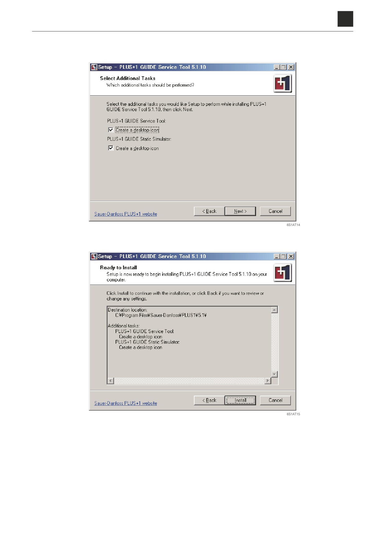
g. Click [Next] to proceed.
• Uncheck the box if you do not wish to create a desktop icon.
h. Click [Install] to start the installation.
8
2. CONNECTION METHODS
6S1AS01
6
2. CONNECTION METHODS
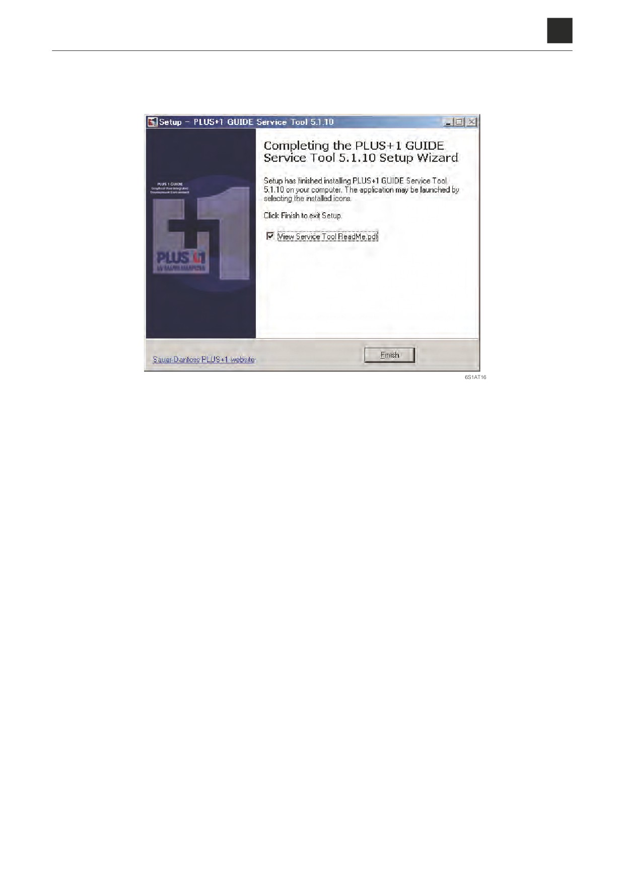
i. The screen shown below will appear if the installation is successful.
Installation of the Maintenance Tool driver will start once the installation of the above file is completed. Proceed
to Step 2-3 to continue.
9
2. CONNECTION METHODS
6S1AS01
6
2. CONNECTION METHODS
2-3. Installation of the Maintenance Tool driver
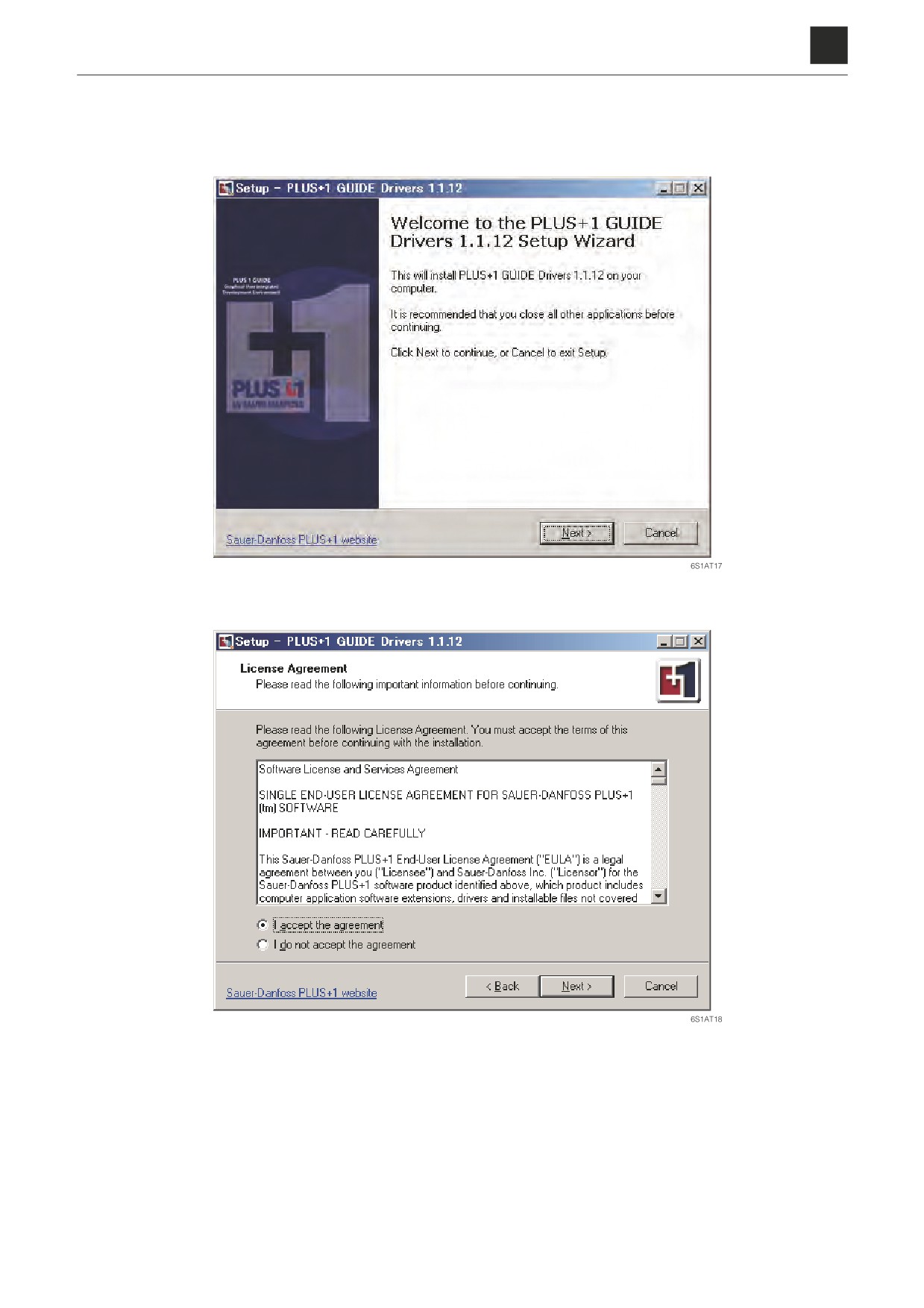
1. Install the Maintenance Tool driver.
a. The window shown below will appear once Step 2-2 has finished. Click the [Next] in the window to proceed.
b. Select “I accept the agreement” and then click [Next] to confirm and proceed.
10
2. CONNECTION METHODS
6S1AS01
6
2. CONNECTION METHODS
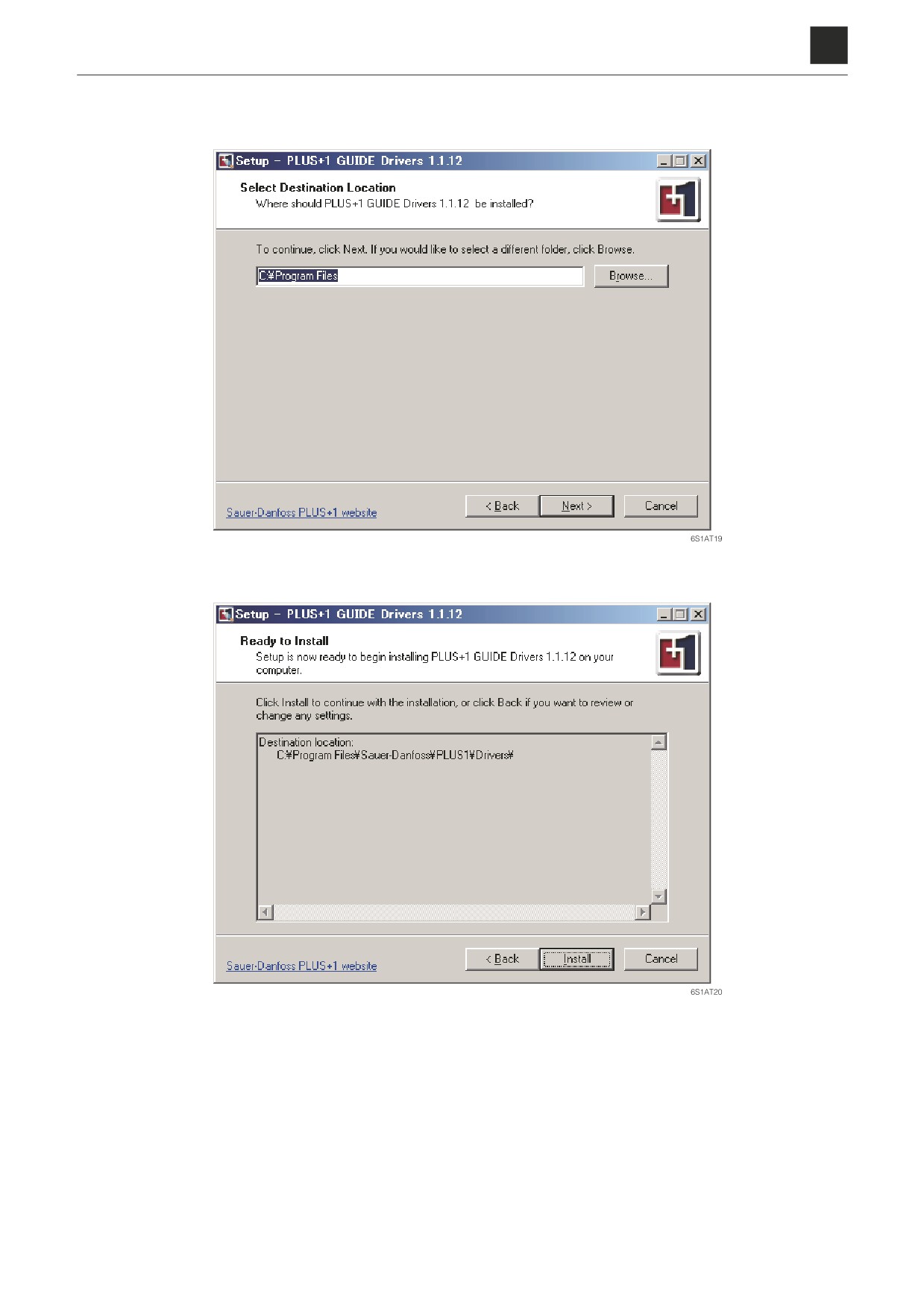
c. Specify the folder for installation of the driver (continue as is unless wanting to use a folder other than the one
selected) and then click [Next] to proceed.
d. Click [Install] to start the installation.
11
2. CONNECTION METHODS
6S1AS01
6
2. CONNECTION METHODS
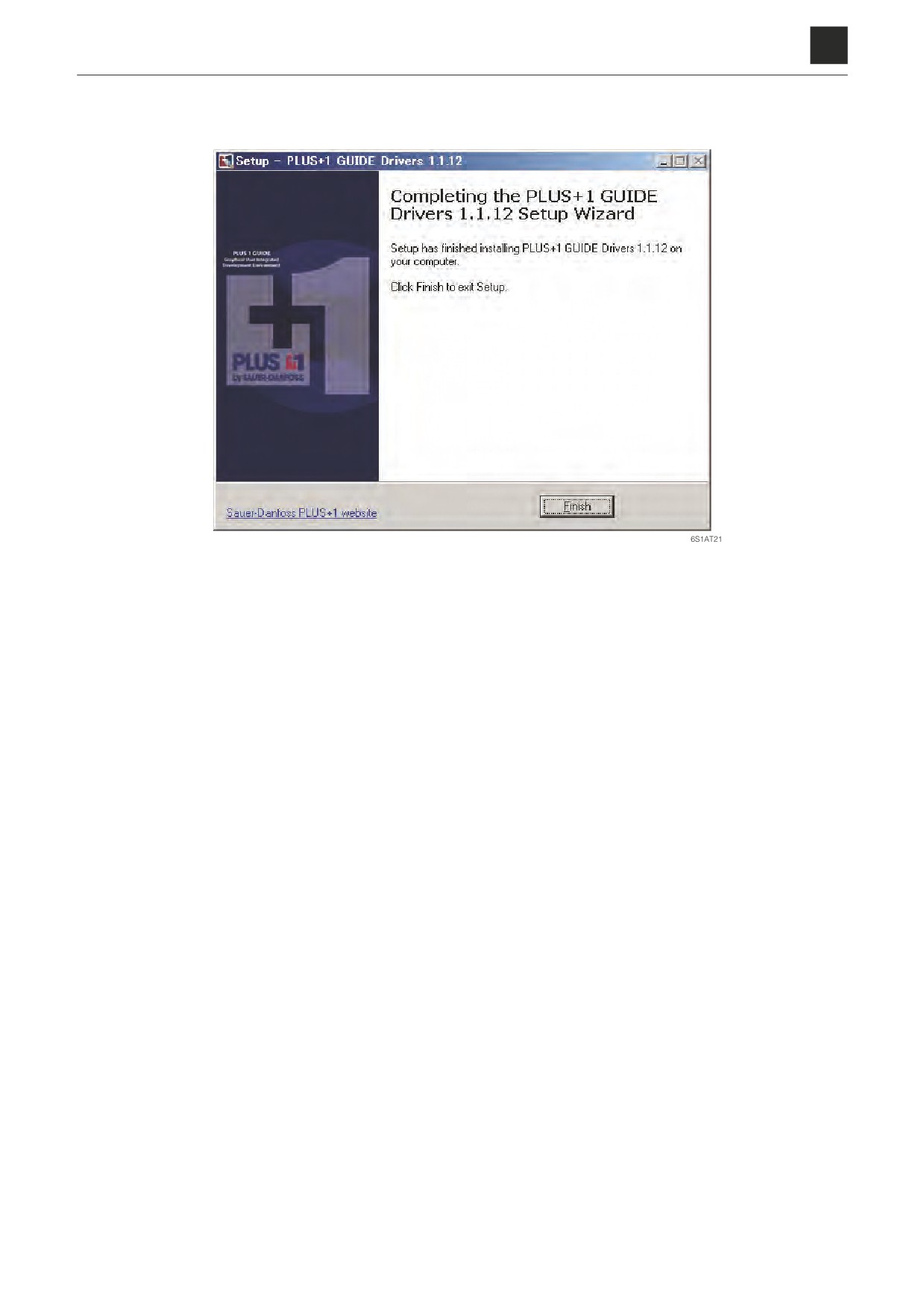
e. The screen shown below will appear if the installation is successful.
Click [Finish] to complete the installation and close the window.
12
2. CONNECTION METHODS
6S1AS01
6
2. CONNECTION METHODS
2-4. Connection to the machine and startup of the Maintenance Software
1. Connect the Maintenance Tool (product no. 17301-
41810) to the USB port on your computer.
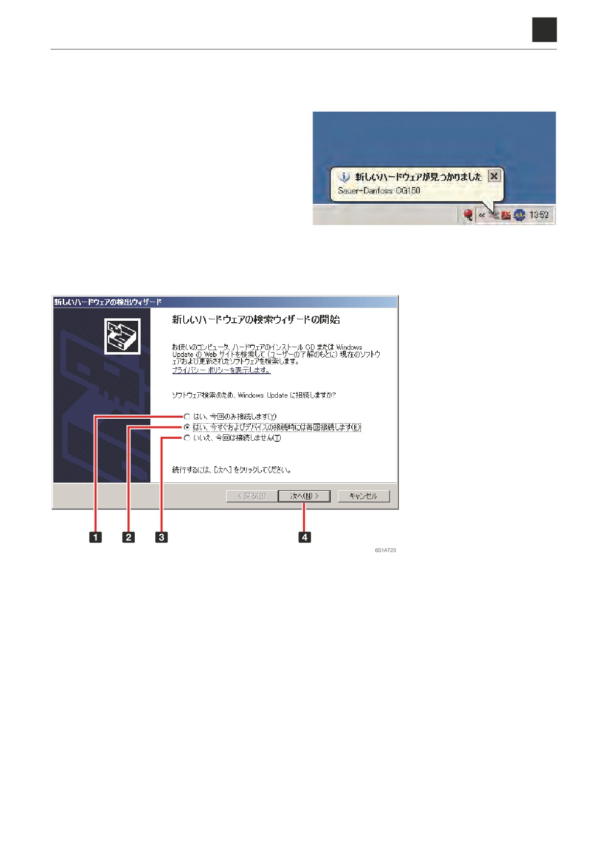
a. The message shown at right will appear as soon
as you connect the Maintenance Tool to the USB
port on your computer and the device is recog-
nized.
Click on the message to start the Found New Hard-
ware Wizard.
6S1AT22
b. Select 2
“Yes, now and every time I connect a device” and then click 4
[Next] to proceed.
1
“Yes, this time only.”
2
“Yes, now and every time I
connect a device.”
3
“No, not this time.”
4
Next
13
2. CONNECTION METHODS
6S1AS01
6
2. CONNECTION METHODS
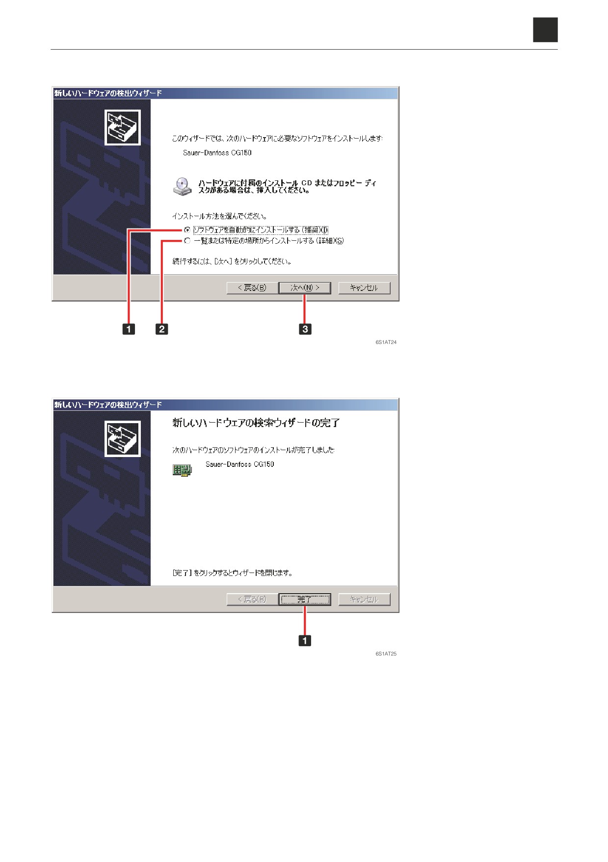
c. Select 1
“Install the software automatically.” Click 4
[Next] to start the Search wizard.
1
“Install the software auto-
matically.”
2
“Install from a list or specific
location.”
3
Next
d. A message such as the one shown below will appear to inform you that the installation has been completed.
Click 1
[Finish] to end the Wizard and close the window.
1
Finish
14
2. CONNECTION METHODS
6S1AS01
6
2. CONNECTION METHODS
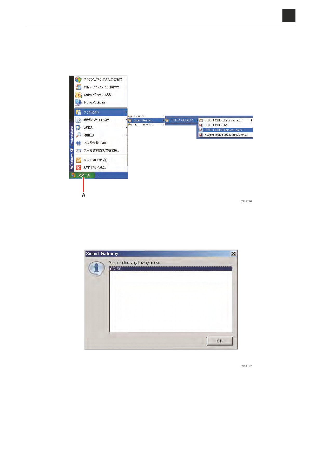
2. Start up the PLUS+1 GUIDE Service Tool installed in Step 2-2.
a. Select [Program] from the Start menu and then click on [Sauer-Danfoss]. Click on PLUS+1 GUIDE 5.1, and se-
lect PLUS+1 GUIDE Service Tool.
• You can also start the program by clicking on the desktop icon if you chose to create one.
b. When the window shown below appears, confirm that [CG150] has been selected and then click [OK] to pro-
ceed.
15
2. CONNECTION METHODS
6S1AS01
6
2. CONNECTION METHODS
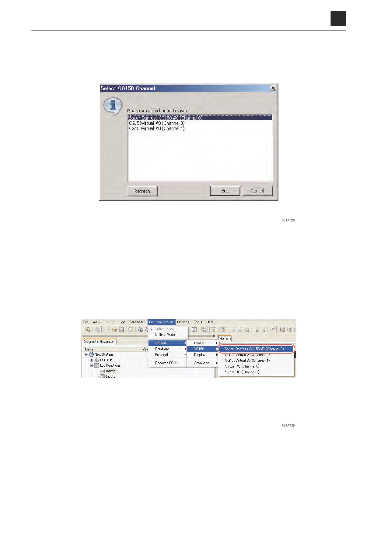
c. When the window shown below appears, confirm that [Sauer-Danfoss CG150 #0 (Channel 0)] has been select-
ed and then click [Set] to proceed.
3. Select [Communication]-[Gateway]-[CG150]-[Sauer-Danfoss CG150 #0 (Channel 0)].
• The Maintenance Tool may not be properly connected if the above is not available as a selection. Make sure
that the Maintenance Tool is firmly connected and then try again.
16
2. CONNECTION METHODS
6S1AS01
6
2. CONNECTION METHODS
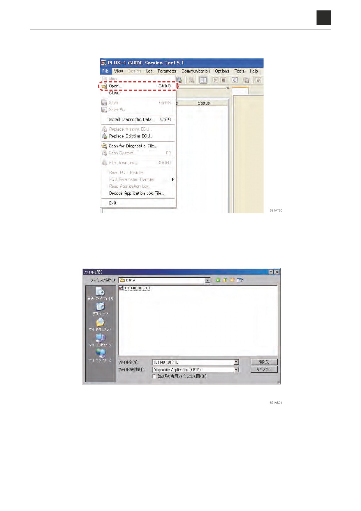
4. Start up the Maintenance Software.
a. Select [File]-[Open].
b. Open the Maintenance Software file (File name: TB1140_***.P1D).
• The file should be located in the save location selected for the CD for installation (product no. 05701-
00005) that was selected in Step 2-1 above.
17
2. CONNECTION METHODS
6S1AS01
6
2. CONNECTION METHODS
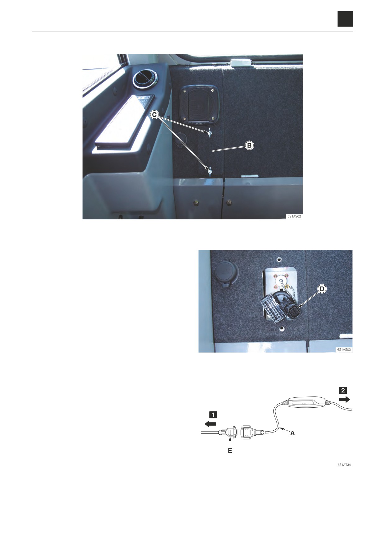
5. Connect to the actual machine.
a. Remove the cover (B) on the floor space on the right side in back of the seat.
• Remove the two screws (C) and then remove the cover (B).
b. There is a connector (D) that is marked with a
“CAN_0” mark tube. Connect the cable assembly
(E) to this connector (D).
c. Connect the cable assembly (E) to the Mainte-
nance Tool (A).
1
To actual machine
2
To computer
18
2. CONNECTION METHODS
6S1AS01
6
3. DESCRIPTION OF FUNCTIONS
3. DESCRIPTION OF FUNCTIONS
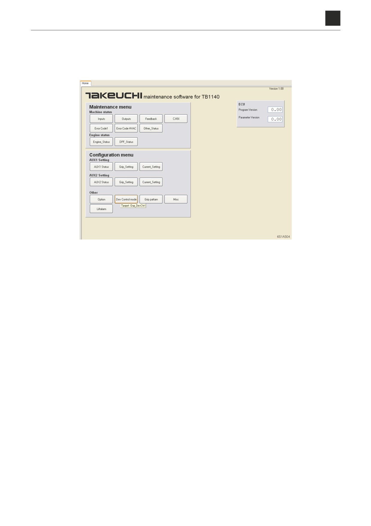
3-1. Main screen
Click the different buttons to jump to the associated pages.
19
3. DESCRIPTION OF FUNCTIONS
6S1AS01
6
3. DESCRIPTION OF FUNCTIONS
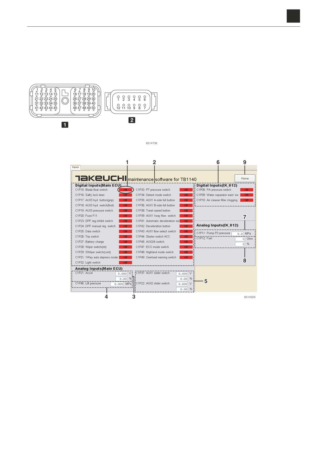
3-2. Machine status
Inputs
1
Pin wiring diagram for the main controller: C1P**
2
Pin wiring diagram for the extension module (IX012):
C1P**
1. Input signal
5. Input signal to the main controller from the aux-
ON: Switch ON
iliary line piping switches
OFF: Switch OFF
Top: Voltage value
2. Input signal to the main controller from the
Bottom: Stroke (-100% to +100%)
switches
6. Input signal to the extension module (IX012)
3. Input signal to the main controller by throttle
from the switches
operation
7. Input signal to the extension module (IX012)
Top: Voltage value
from the pressure sensor
Bottom: Degree of release for the accelerator
8. Input signal to the extension module (IX012)
pedal
from the fuel sender
4. Input value to the controller from the pressure
Top: Resistance value
sensor
Bottom: Level of fuel remaining (0% to 100%)
9. Return to the Main screen
20
3. DESCRIPTION OF FUNCTIONS
6S1AS01
6
3. DESCRIPTION OF FUNCTIONS
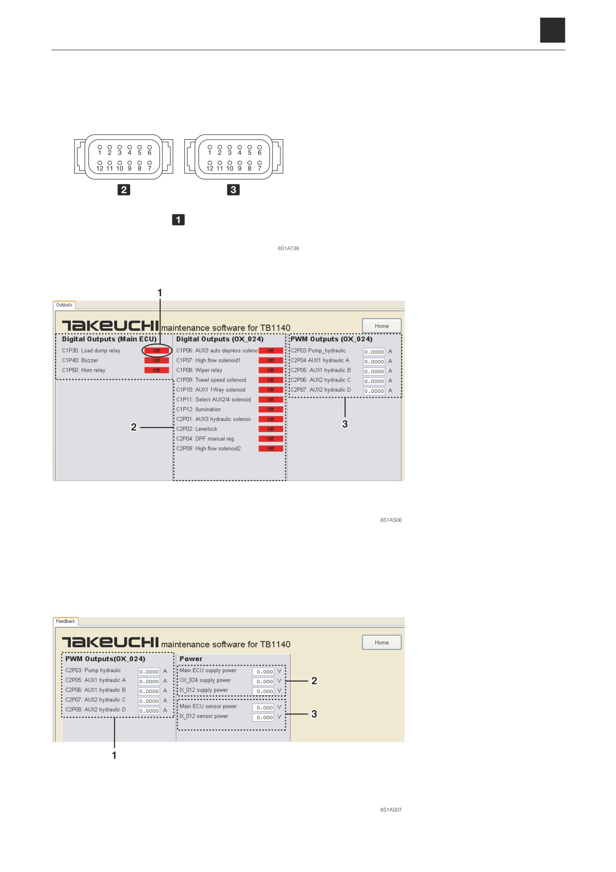
Outputs
1
Pin wiring diagram for the IX012
2
A-key (Gray): C1P**
3
B-key (Black): C2P**
1. Output signal
ON: Switch ON
OFF: Switch OFF
2. Output signals to the devic-
es from the controller
3. Target output current to the
devices from the extension
module (IX012)
Feedback
1. Actual output current for the
devices
2. Power supply voltage (12 V)
Top: Main engine control
unit (ECU)
Middle: Extension module
(OX_024)
Bottom: Extension module
(IX_012)
3. Sensor voltage (5 V)
Top: Main controller
Bottom: Extension module
(IX_012)
21
3. DESCRIPTION OF FUNCTIONS
6S1AS01
6
3. DESCRIPTION OF FUNCTIONS
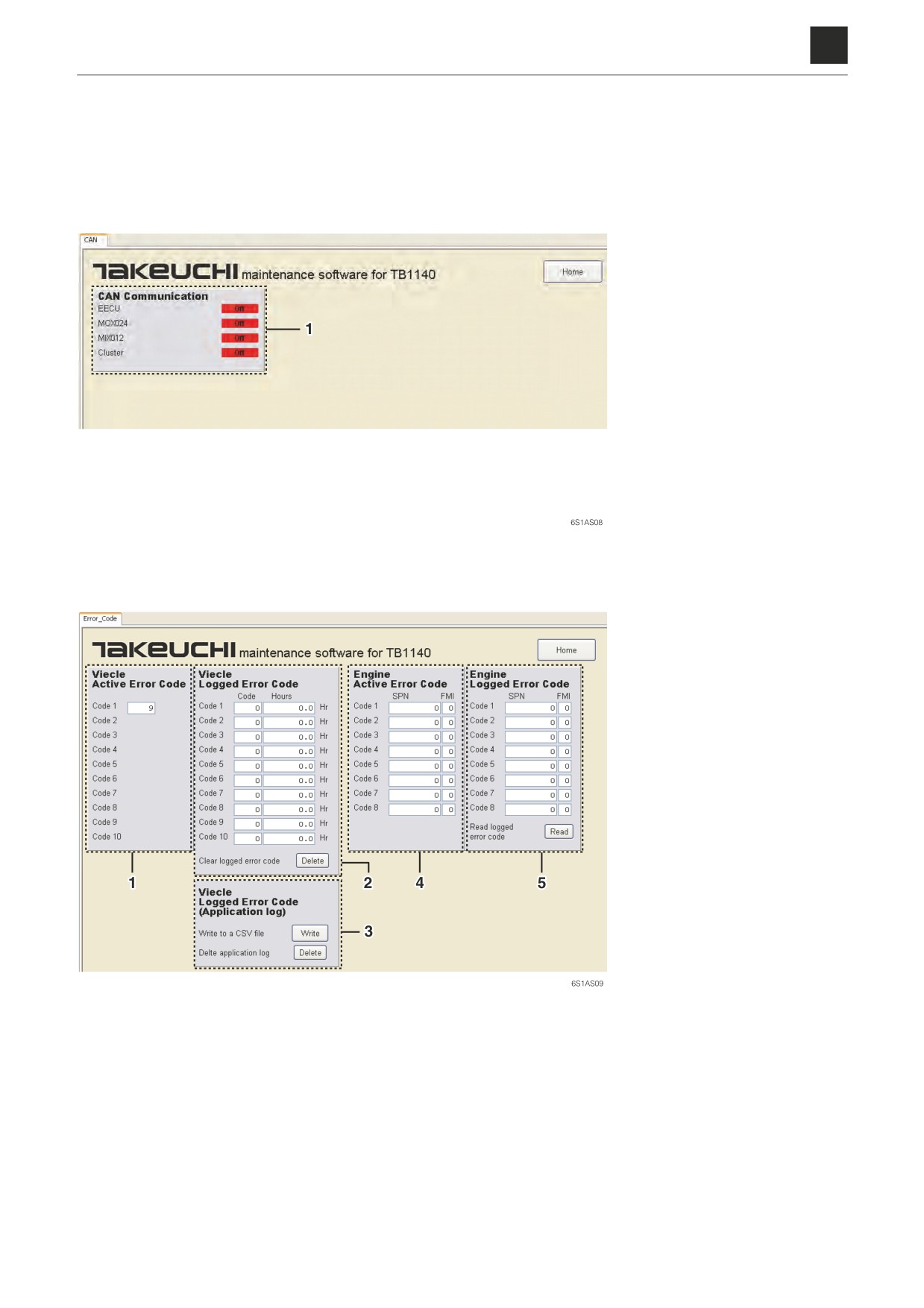
CAN
1. CAN communications state
Switching back and forth
between ON/OFF: Normal
Staying OFF: Abnormal
Error_Code
1. Current malfunction codes for the machine
4. Current malfunction codes for the engine
2. Past malfunction codes for the machine
5. Past malfunction codes for the engine
3. Current malfunction codes triggered on the ma-
Read: Used to display a list of malfunction codes.
chine are read out.
Write: Current malfunction codes triggered on the
machine are read out in CSV format.
The P1A and CSV files for the extension modules
are created with the same content.
Delete: Used to delete the malfunction code log.
22
3. DESCRIPTION OF FUNCTIONS
6S1AS01
6
3. DESCRIPTION OF FUNCTIONS
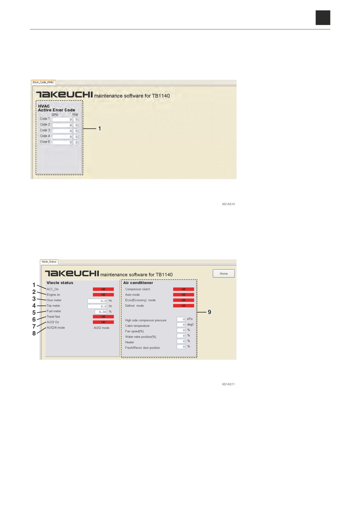
Error_Code_HVAC
1. This function displays the
HVAC (air conditioner) error
codes.
Status of other parts and sections
1. Starter switch position
6. Travel speed
2. Engine status
ON: 2nd-speed
ON: Engine running
OFF: 1st-speed
OFF: Engine stopped
7. 3rd auxiliary line piping
3. Hour meter
8. 2nd/4th auxiliary line piping
4. Trip meter
9. Air conditioner status
5. Fuel gauge (0% to 100%)
23
3. DESCRIPTION OF FUNCTIONS
6S1AS01
6
3. DESCRIPTION OF FUNCTIONS
3-3. Engine status
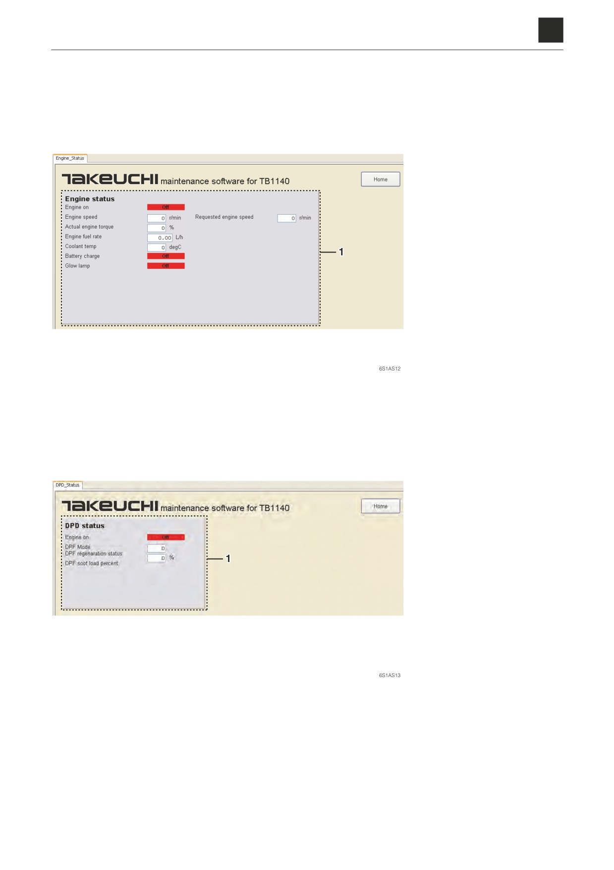
Engine_Status
1. Engine status
DPF_Status
1. DPF status
24
3. DESCRIPTION OF FUNCTIONS
6S1AS01
6
3. DESCRIPTION OF FUNCTIONS
3-4. AUX1 Settings
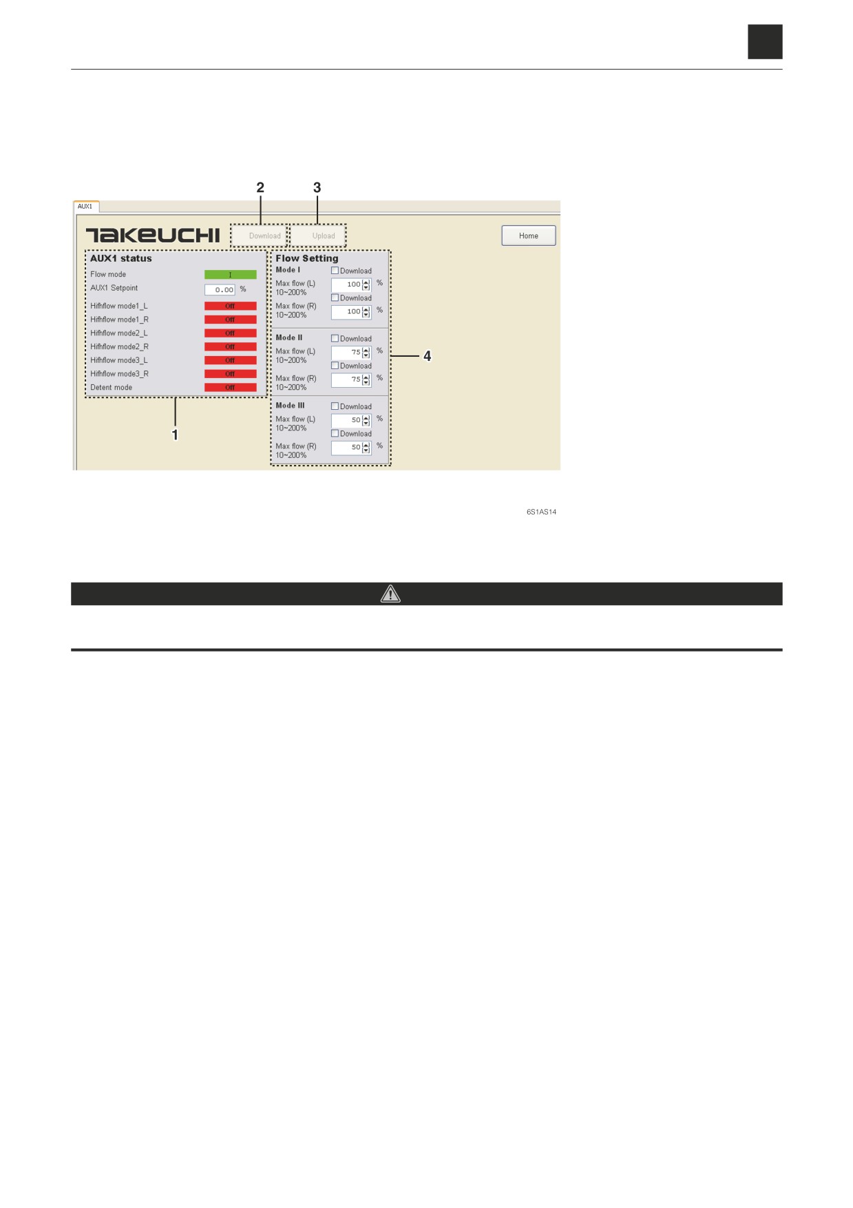
AUX1 status
1. Current settings for the 1st
auxiliary line piping
2. Download: Used to down-
load the settings to the con-
troller.
3. Upload: Used to upload the
current settings from the
controller.
4. Flow rate for the flow select
mode
Making adjustments
DANGER
Make sure to exercise extreme caution after making adjustments as the machine could run in an unexpected way, which
could in certain cases cause severe injury or even death. Be extremely careful when operating the auxiliary line piping.
a. Click on (3) to pull up the current setting conditions (4).
b. Click above or below (4) to set the flow rate to any desired value.
c. Click on the box to the left of “Download” to check it.
d. Click on (2) to download the setting values set in b. to the controller.
25
3. DESCRIPTION OF FUNCTIONS
6S1AS01
6
3. DESCRIPTION OF FUNCTIONS
Grip_Settings
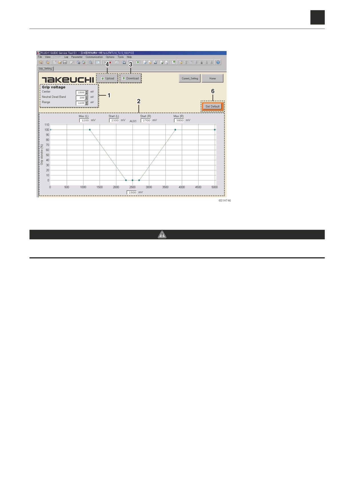
1. Set voltage
2. Voltage
(mV)-Current
(%)
characteristics graph
3. Download: Used to down-
load the settings to the con-
troller.
4. Upload: Used to upload the
current settings from the
controller.
5. Set Default: Used to return
the settings to the default
values.
Making adjustments
DANGER
Make sure to exercise extreme caution after making adjustments as the machine could run in an unexpected way, which
could in certain cases cause severe injury or even death. Be extremely careful when operating the auxiliary line piping.
The amount of voltage applied to the solenoid valve and the flow rate for the auxiliary line piping may vary depending
on the slide switch operation. Here, an explanation will be given for a method for adjusting the flow rate varying with
changes in voltage.
a. Click on (4) to pull up the current setting conditions (1) and (2).
b. Click above or below (1) to set the option setting to any desired value.
c. Click on (3) to download the setting values set in b. to the controller.
Example settings
For settings with Center: 2500 mV, Neutral Dead Band: 200 mV, Range: 1100 mV
There will be no operation within the 2500 mV ± 200 mV band.
There will be operation within the 1200 mV to 2300 mV and 2700 mV to 3800 mV bands.
26
3. DESCRIPTION OF FUNCTIONS
6S1AS01
6
3. DESCRIPTION OF FUNCTIONS
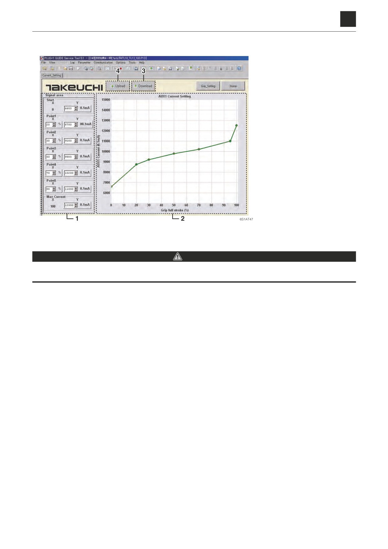
Current_Settings
1. Set current
2. Slide switch stroke (%)-Cur-
rent (×0.1 mA) characteris-
tics graph
3. Download: Used to down-
load the settings to the con-
troller.
4. Upload: Used to upload the
current settings from the
controller.
Making adjustments
DANGER
Make sure to exercise extreme caution after making adjustments as the machine could run in an unexpected way, which
could in certain cases cause severe injury or even death. Be extremely careful when operating the auxiliary line piping.
The amount of voltage applied to the solenoid valve and the flow rate for the auxiliary line piping may vary depending
on the slide switch operation. Here, an explanation will be given for a method for adjusting the current according to
slide switch operation.
a. Click on (4) to pull up the current setting conditions (1) and (2).
b. Click above or below (1) to set the option setting to any desired value.
c. Click on (3) to download the setting values set in b. to the controller.
27
3. DESCRIPTION OF FUNCTIONS
6S1AS01
6
3. DESCRIPTION OF FUNCTIONS
3-5. AUX2 Setting
This function can be used to set the 2nd/4th auxiliary line piping settings. The operation method is the same as for AUX1
Settings.
“3-4. AUX1 Settings”
28
3. DESCRIPTION OF FUNCTIONS
6S1AS01
6
3. DESCRIPTION OF FUNCTIONS
3-6. Others
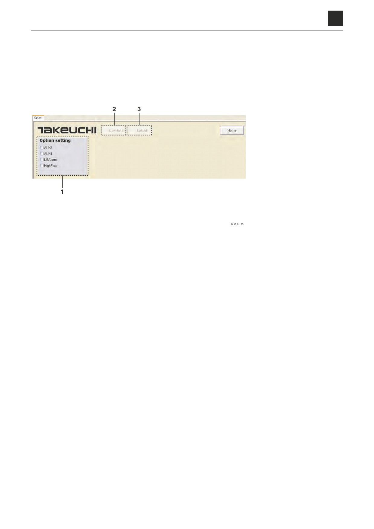
Options
1. Option settings
2. Download: Used to down-
load the settings to the con-
troller.
3. Upload: Used to upload the
current settings from the
controller.
Setting the option settings
a. Click on (3) to pull up the current setting conditions (1).
b. After making settings for the different options, check the set items and then click (2).
29
3. DESCRIPTION OF FUNCTIONS
6S1AS01