Takeuchi Hydraulic excavator TB1140 (Serial No. 514400002~). Operator's Manual - page 11
TROUBLESHOOTING
5
SLEWING
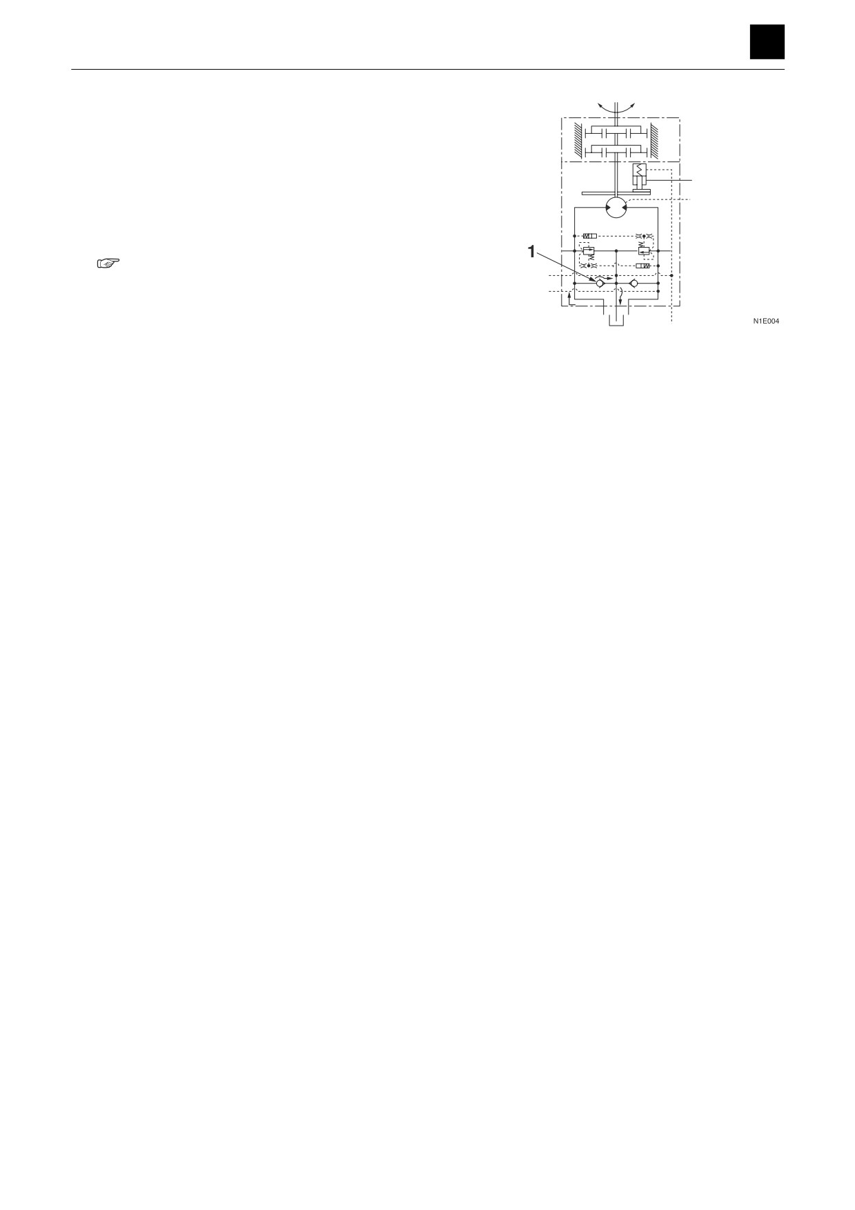
4. Check the check valve in the slew brake valve.
No left or right slew movement occurs if foreign mat-
ter trapped in one of the check valves (1) or if the
valve is sticking.
• If foreign matter is trapped in either of the check
valves, the hydraulic oil returns from the check
valve into the tank.
5. Slew motor is faulty.
“4. Disassembly and assembly, Slew motor”
4
SLEWING
5D0AS00
TROUBLESHOOTING
5
SLEWING
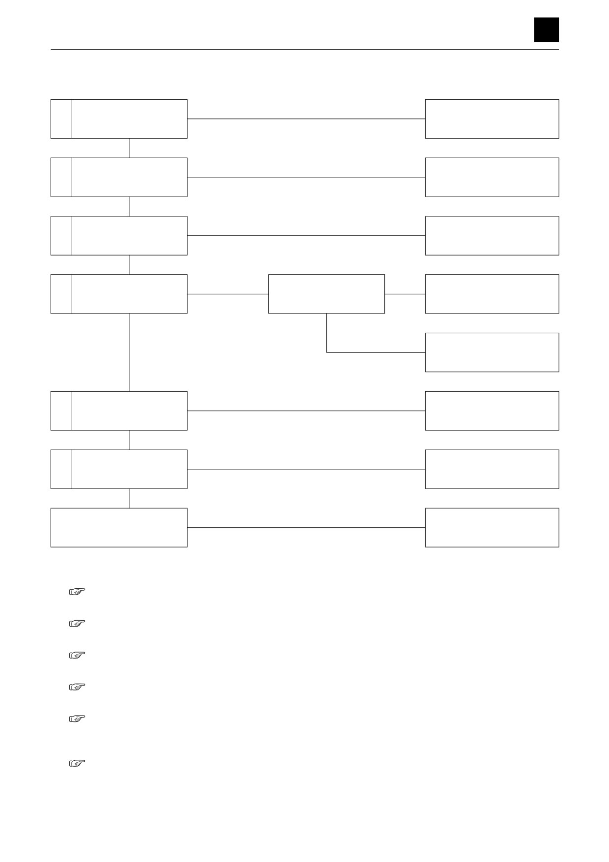
Slewing is slow or lacks force.
Within spec
Is the slewing time within
1
Normal
spec?
Slow
Faulty
Repair or replace the pilot
2
Check the pilot valve.
valve.
Normal
Faulty
Repair or replace the housing
3
Check the control valve.
block.
Normal
Pressure too low
Adjust the slew relief
4
Check the slew pressure.
Adjust to the set pressure.
valve pressure.
Normal
Pressure does not in-
crease.
Repair or replace the relief
valve.
Faulty
Check the check valves
Repair or replace the brake
5
in the slew brake valve.
valve.
Normal
Faulty
Repair or replace the slew
6
Check the slew motor.
motor.
Normal
Slew bearing is faulty.
Replace
1. Is the slewing time within spec?
“2. Service data, Performance criteria”
2. Check the pilot valve.
“No slew movement, Check the pilot valve.”
3. Check the control valve.
“No slew movement, Check the control valve.”
4. Check the slew pressure.
“2. Service data, Performance criteria”
5. Check the check valve in the slew brake valve.
”No slew movement, Check the check valve in
the slew brake valve.”
6. Check the slew motor.
“No slew movement, Check the slew motor.”
5
SLEWING
5D0AS00
TROUBLESHOOTING
5
SLEWING
Slewing occurs but overrun is large when slewing stops or slewing fails to stop.
Within spec
Is the overrun when slew-
1
Normal
ing stops within spec?
Out-of-spec
Faulty
Repair or replace the pilot
2
Check the pilot valve.
valve.
Normal
Faulty
Repair or replace the housing
3
Check the control valve.
block.
Normal
Faulty
Check the check valve in
Repair or replace the brake
4
the slew brake valve.
valve.
Normal
Pressure too low
Adjust the slew relief
5
Check the slew pressure.
Adjust to the set pressure.
valve pressure.
Pressure does not in-
crease.
Repair or replace the relief
valve.
1. Is the overrun when slewing stops within spec?
“2. Service data, Performance criteria”
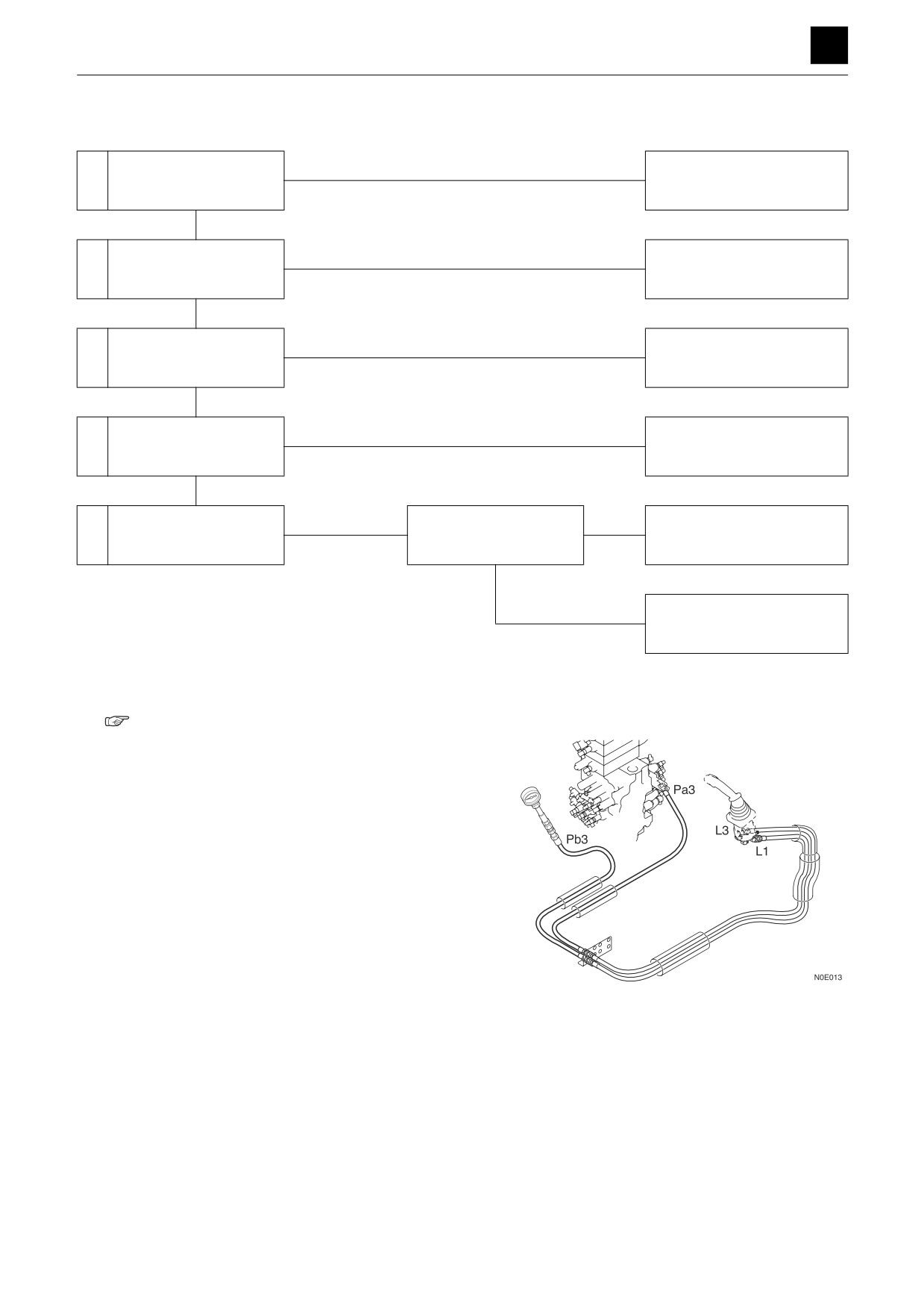
2. Check the pilot valve.
Check to see if the pilot valve spool returns to the
neutral position when the operation lever (slew) is re-
leased after operation. Disconnect the hose con-
necting the pilot valve and control valve (Pa3, Pb3)
from the control valve, and attach a pressure gauge
to the disconnected hose.
• Read the pressure gauge when the lever (slew) is
released after operation.
• If the pressure is zero, the pilot valve is normal.
6
SLEWING
5D0AS00
TROUBLESHOOTING
5
SLEWING
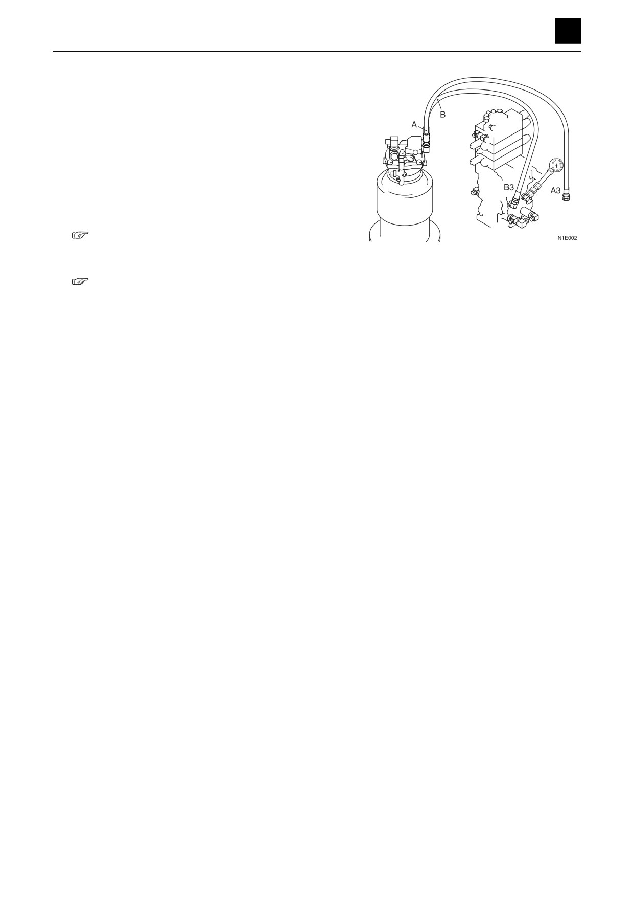
3. Check the control valve.
Check to see if the control valve (slew section) spool
returns to the neutral position when the operation le-
ver (slew) is returned to the neutral position. Discon-
nect the hose connecting the control valve (B3, A3)
and the slew motor from the control valve, and attach
a pressure gauge to the port of the valve.
• Read the pressure gauge when the lever (slew) is
released after operation.
• If the pressure is zero, the control valve is normal.
4. Check the check valve in the slew brake valve.
“No right or left slew movement, Check the
check valve in the slew brake valve.”
5. Check the slew pressure.
“2. Service data, Performance criteria”
7
SLEWING
5D0AS00
TROUBLESHOOTING
5
SLEWING
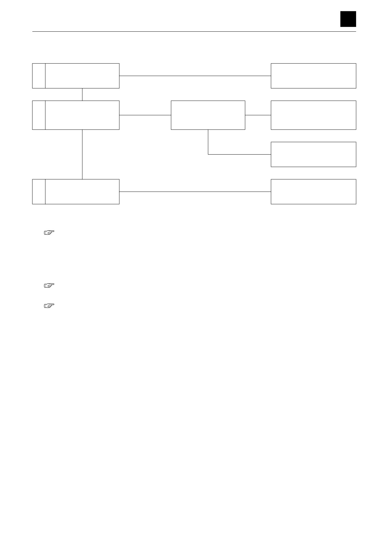
When stopped on a slope, the upper-structure cannot maintain its posture.
Within spec
Is the slew spontaneous
1
Normal
drop within spec?
Out-of-spec
Pressure too low
Adjust the relief valve
2
Check the slew pressure.
pressure for the slew
Adjust to the set pressure.
brake valve.
Normal
Pressure does not in-
crease.
Repair or replace the slew re-
lief valve.
Faulty
Repair or replace the slew
3
Check the slew motor.
motor.
1. Is the slew spontaneous drop within spec?
“2. Service data, Performance criteria”
2. Check the slew pressure.
Measure the pressure at the right and left slew relief
valves.
• If the measured value is within the specifications,
the valve is normal.
“2. Service data, Performance criteria”
3. Check the slew motor.
“No slew movement, Check the slew motor.”
8
SLEWING
5D0AS00
TROUBLESHOOTING
BOOM 5
BOOM
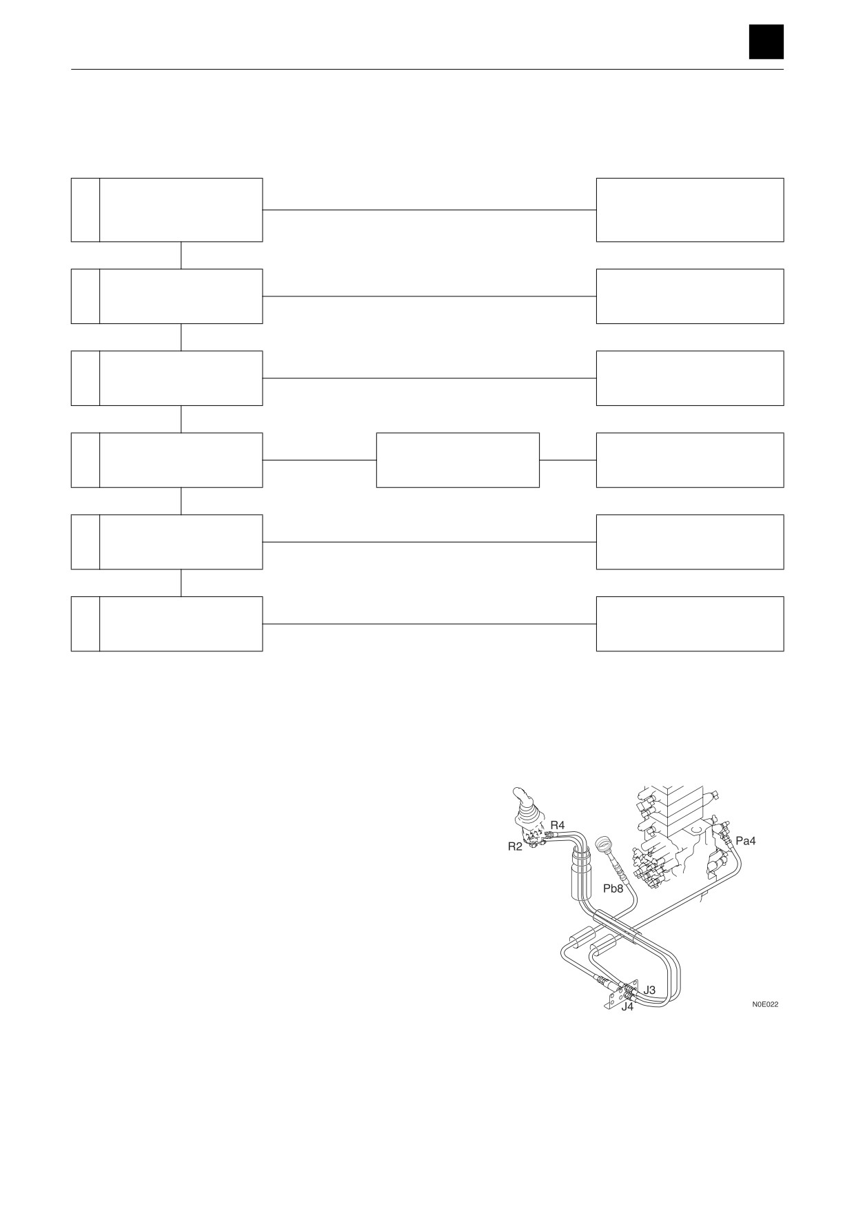
Boom cylinder does not move.
Check the operation of
Abnormal
Check the main relief valve
1
actuators other than the
and pump.
boom cylinder.
Normal
Faulty
Repair or replace the pilot
2
Check the pilot valve.
valve.
Normal
Faulty
3
Check the control valve.
Repair or replace.
Normal
Problem solved
Test the port relief valve
The port relief valve is
Repair or replace the port re-
4
with a replacement valve.
faulty.
lief valve.
No change
Faulty
Check the emergency
5
Replace
shut-off valve.
Normal
Faulty
Repair or replace the boom
6
Check the boom cylinder.
cylinder.
1. Check the operation of actuators other than the boom
cylinder.
• Check whether only the boom operation is faulty.
If the operation of other actuators is also defective,
see Overall machine.
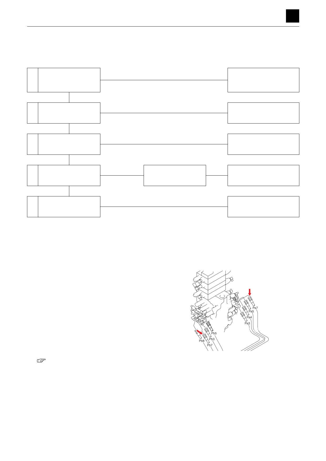
2. Check the pilot valve.
Disconnect the hose between the pilot valve and
control valve (Pa4, Pb8) from the control valve, and
attach a pressure gauge to the disconnected hose.
• Operate the lever (boom), and measure the pres-
sure.
• The pilot valve is working normally if the pressure
varies between 0 MPa and 3.9 MPa (0 and 566
psi), according to the lever angle.
If the measured pressure is abnormal, replace the pi-
lot valve.
1
BOOM
5G0AS00
TROUBLESHOOTING
BOOM 5
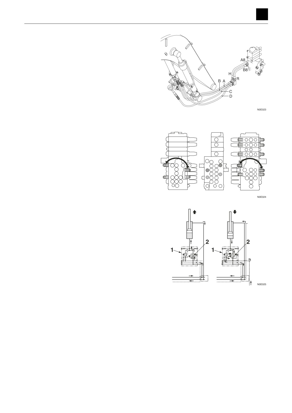
3. Check the control valve.
Disconnect the cylinder end of each of the hoses (A,
B, C, D) connecting the control valve and boom cyl-
inders, and attach a pressure gauge to each of the
disconnected hoses.
• Operate the lever (boom), and measure the pres-
sure.
Supply pressure: 34.3 MPa (4975 psi)
If the measured pressure is abnormal, replace the
control valve.
4. Test the port relief valve with a replacement valve.
If the boom cylinder is able to operate with a replace-
ment valve taken out from a normal port relief valve
of the arm, then the port relief valve on the boom side
is faulty.
5. Check the emergency shut-off valve.
Note: The emergency shut-off valve (1) allows pres-
sure to be supplied to the cylinder side from
the check valve (2) when the boom is raised,
which enables the boom to be prevented from
being lowered by the check valve (2) even if
some problem arises such as due to damage
in the hose on the downstream side on the low-
er part of the check valve.
When the boom is lowered, pilot pressure for
boom (lower) operation is supplied to the
emergency shut-off valve (1), and the emer-
gency shut-off valve (1) connects together the
cylinder head side and the return side on the
control valve.
2
BOOM
5G0AS00
TROUBLESHOOTING
BOOM 5
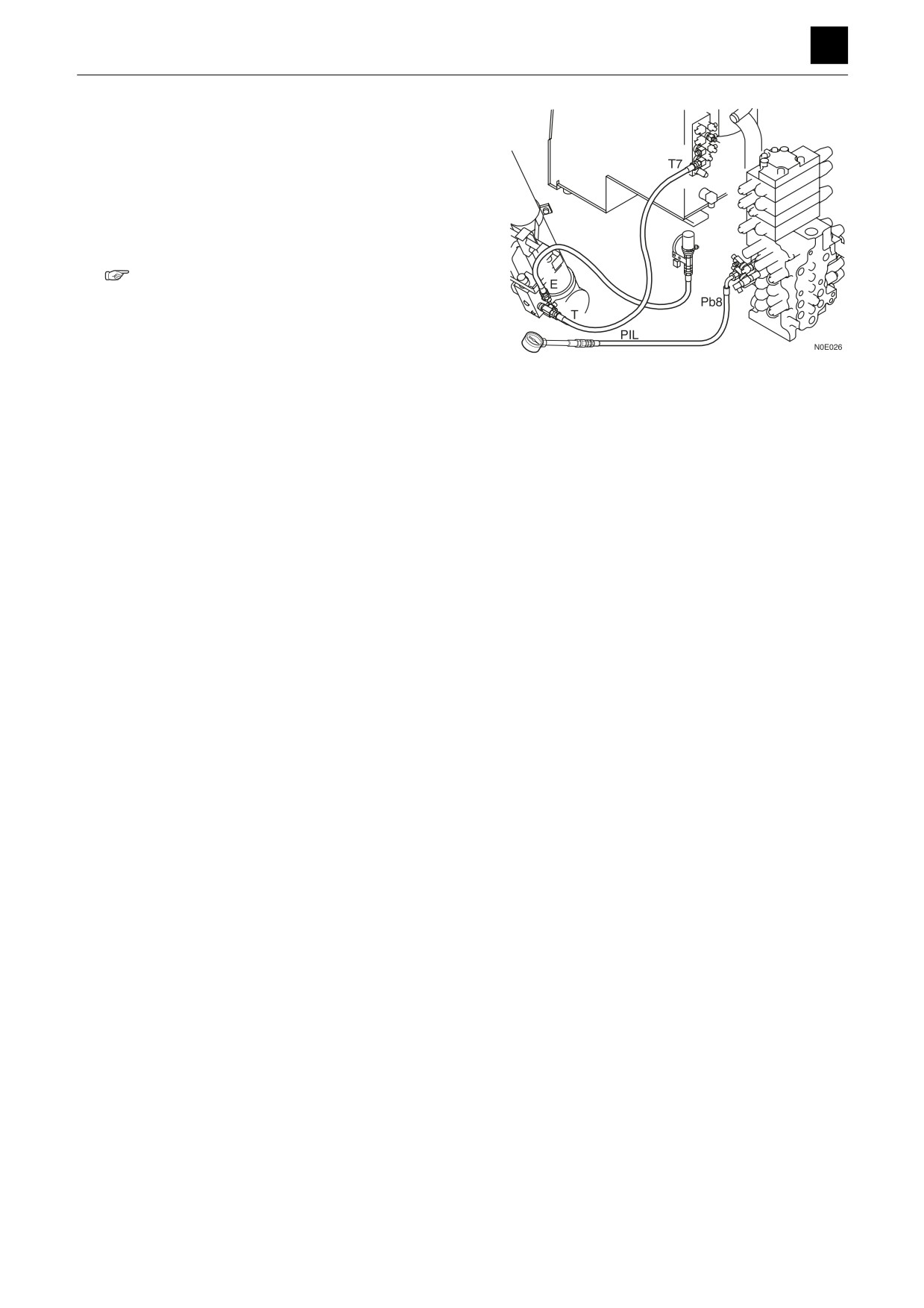
a. Disconnect the hose from the emergency shut-off
valve (PIL port), and attach a pressure gauge to
the hose.
b. Operate the lever (boom), and measure the pres-
sure.
c. The emergency shut-off valve is faulty if the sup-
ply pressure is 3.9 MPa (566 psi).
6. Check the boom cylinder.
“4. Disassembly and assembly, Cylinders”
3
BOOM
5G0AS00
TROUBLESHOOTING
BOOM 5
Boom cylinder is slow or lacks force.
Within spec
Is the speed of the boom
1
Normal
cylinder within spec?
Out-of-spec
Faulty
Repair or replace the pilot
2
Check the pilot valve.
valve.
Normal
Faulty
Repair or replace the housing
3
Check the control valve.
block.
Normal
Problem solved
Test the port relief valve
The port relief valve is
Repair or replace the port re-
4
with a replacement valve.
faulty.
lief valve.
No change
Faulty
Repair or replace the boom
5
Check the boom cylinder.
cylinder.
1. Is the speed of the boom cylinder within spec?
“2. Service data, Performance criteria”
2. Check the pilot valve.
“Boom, Boom cylinder does not move.”
3. Check the control valve.
“Boom, Boom cylinder does not move.”
4. Test the port relief valve with a replacement valve.
“Boom, Boom cylinder does not move.”
5. Check the boom cylinder.
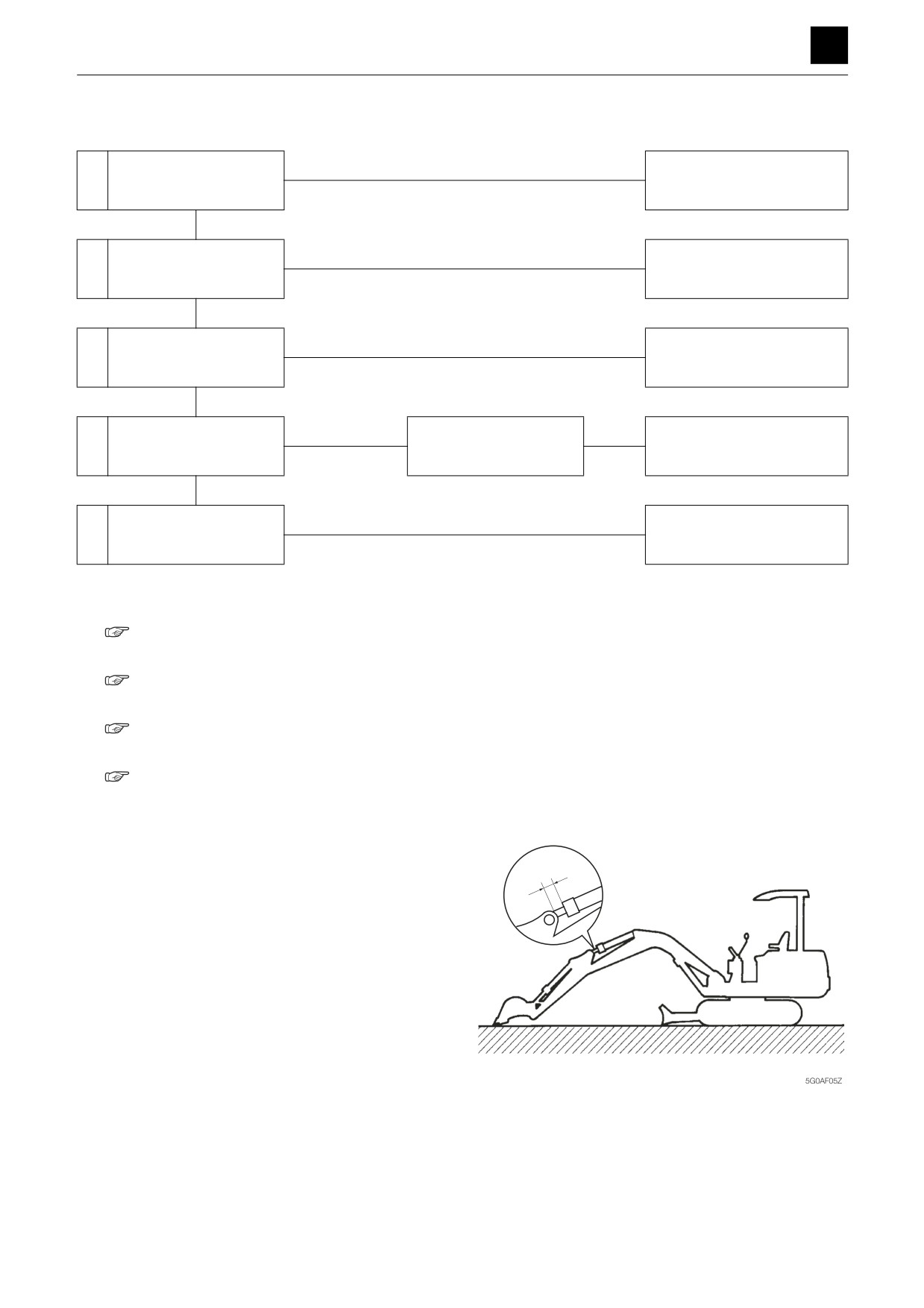
Check for leakage inside the boom cylinder (1).
a. With the bucket cylinder fully retracted and the
arm cylinder extended slightly from the fully re-
tracted position, lower the bucket tip to the
ground.
4
BOOM
5G0AS00
TROUBLESHOOTING
BOOM 5
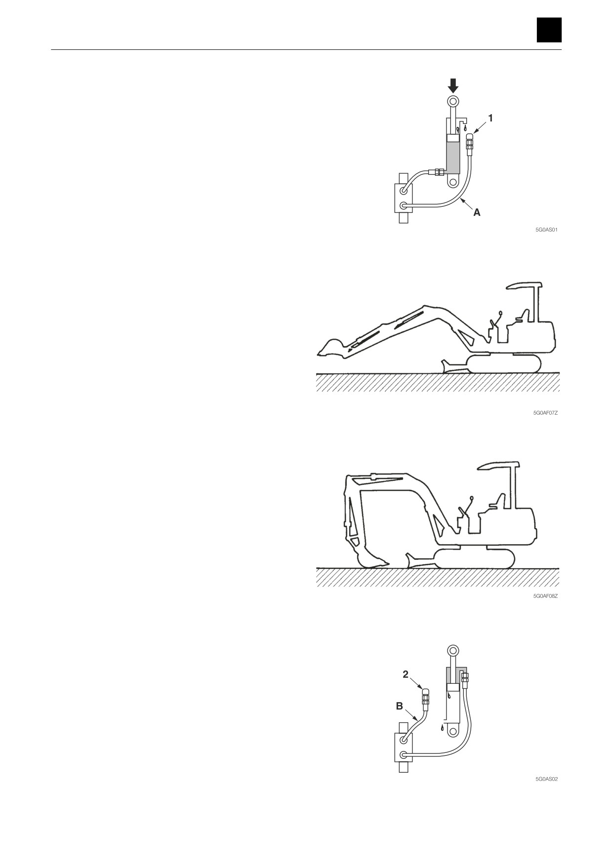
b. Disconnect the hose (A) from the rod end only,
and drain the oil from the piping. Insert a plug (1)
into the disconnected hose.
• Check the right and left cylinders separately,
one at a time. The two hoses should be discon-
nected from the cylinder that is not being
checked during the check of the other cylinder
and each hose fitted with a plug on the end that
was disconnected.
c. Retract the arm cylinder to lift the bucket off the
ground. If oil leaks from the cylinder piping from
which the hose was disconnected and the boom
cylinder rod retracts, the cylinder is leaking inter-
nally. If no oil leaks from the cylinder piping and
the boom cylinder rod retracts, the control valve is
leaking internally.
Check for leakage inside the boom cylinder (2).
a. Set the machine in the posture shown in the fig-
ure.
b. Disconnect the hose (B) from the head end, and
drain the oil from the cylinder piping. Insert a plug
(2) into the disconnected hose.
• Check the right and left cylinders separately,
one at a time. The two hoses should be discon-
nected from the cylinder that is not being
checked during the check of the other cylinder
and each hose fitted with a plug on the end that
was disconnected.
5
BOOM
5G0AS00
TROUBLESHOOTING
BOOM 5
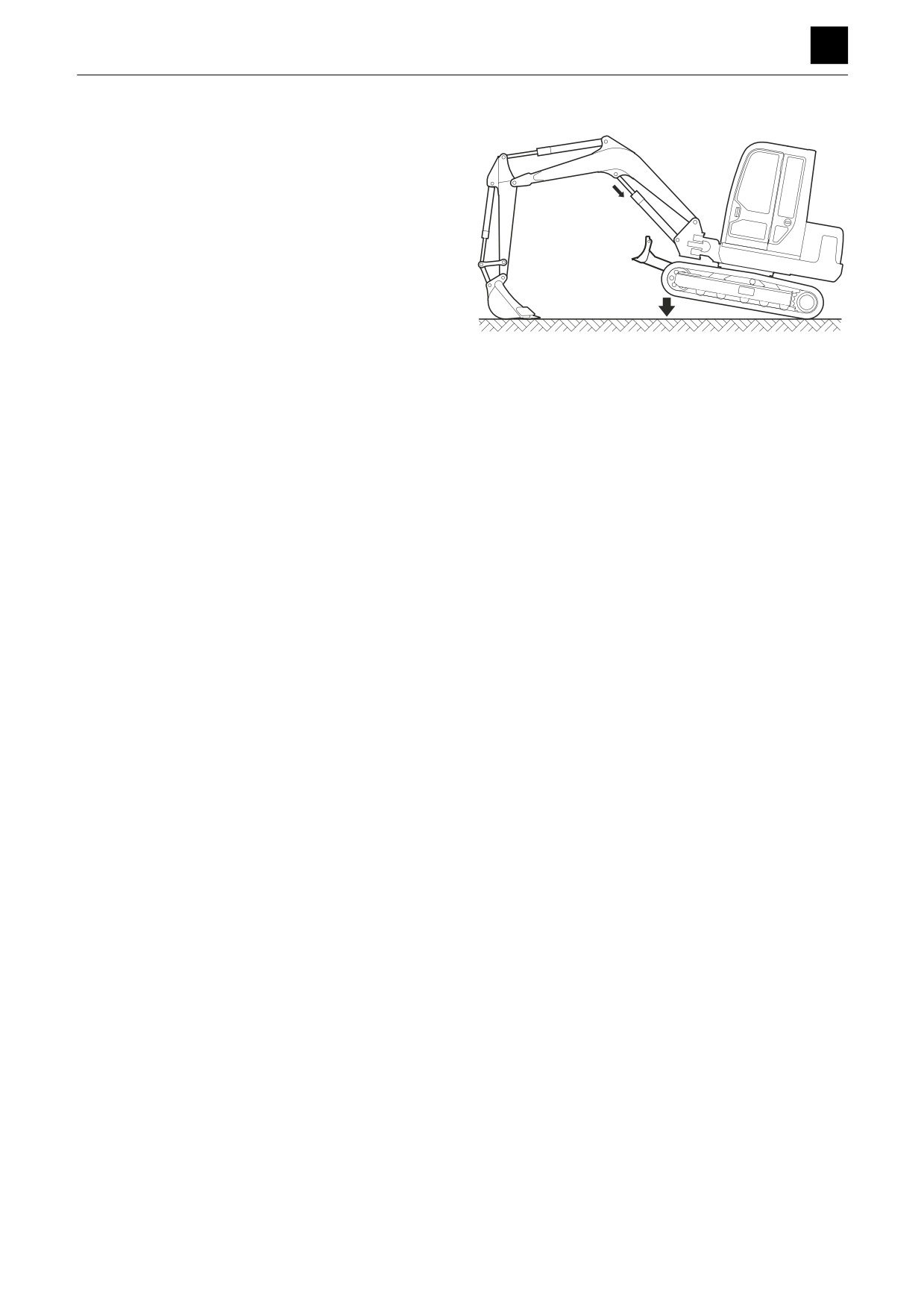
c. Operate the bucket to raise the machine body. If
oil leaks from the cylinder piping from which the
hose was disconnected and the boom cylinder
rod extends, the cylinder is leaking internally.
If no oil leaks from the cylinder piping and the
boom cylinder rod extends, the control valve is
leaking internally.
If the cylinder is damaged internally, the system
must be flushed out to remove any debris.
5G0AS03
6
BOOM
5G0AS00
TROUBLESHOOTING
BOOM 5
Spontaneous drop of the boom cylinder is too large.
Is the spontaneous drop
Within spec
1
of the boom cylinder with-
Normal
in spec?
Out-of-spec
Faulty
Check for leakage inside
Repair or replace the boom
2
the boom cylinder.
cylinder.
Normal
Problem solved
Test the port relief valve
The port relief valve is
Repair or replace the port re-
3
with a replacement valve.
faulty.
lief valve.
Normal
4
Check the control valve.
Replace the housing block.
1. Is the spontaneous drop of the boom cylinder within
spec?
“2. Service data, Performance criteria”
2. Check for leakage inside the boom cylinder.
“Boom, Boom cylinder is slow or lacks force.”
3. Test the port relief valve with a replacement valve.
“Boom, Boom cylinder does not move.”
4. Check the control valve.
“Boom, Boom cylinder does not move.”
7
BOOM
5G0AS00
TROUBLESHOOTING
ARM 5
ARM
Arm cylinder does not move.
Check the operation of
Abnormal
Check the main relief valve
1
actuators other than the
and pump.
arm cylinder.
Normal
Faulty
Repair or replace the pilot
2
Check the pilot valve.
valve.
Normal
Faulty
3
Check the control valve.
Repair or replace.
Normal
Problem solved
Test the port relief valve
The port relief valve is
Repair or replace the port re-
4
with a replacement valve.
faulty.
lief valve.
No change
Faulty
Check the emergency
Replace the emergency shut-
5
shut-off valve.
off valve.
Normal
Faulty
Repair or replace the arm cyl-
6
Check the arm cylinder.
inder.
1. Check the operation of actuators other than the arm
cylinder.
• Check whether only the arm operation is faulty.
If the operation of other actuators is also defective,
see Overall machine.
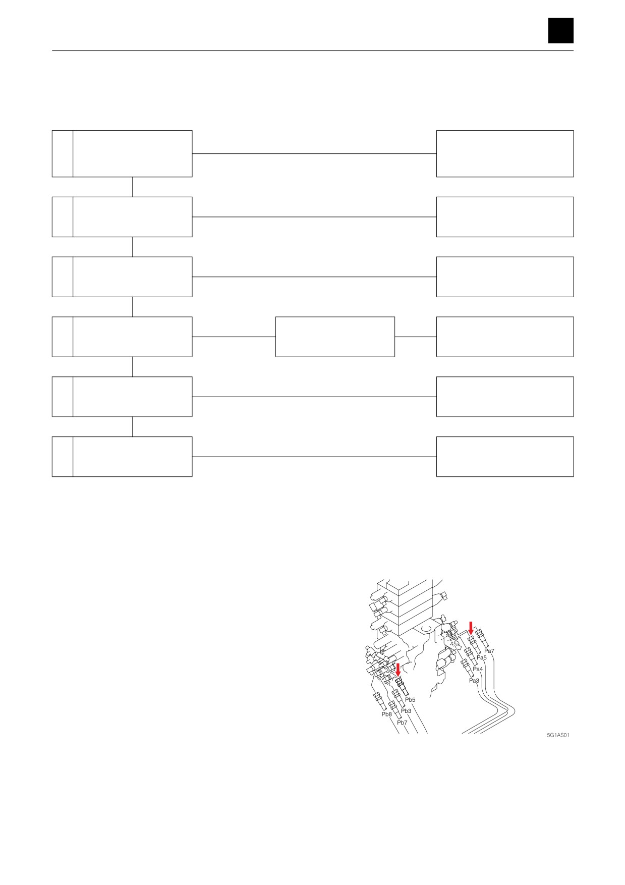
2. Check the pilot valve.
Disconnect the hose between the pilot valve and
control valve (Pa5, Pb5) from the control valve, and
attach a pressure gauge to the disconnected hose.
• Operate the lever (arm), and measure the pres-
sure.
• The pilot valve is working normally if the pressure
varies between 0 MPa and 3.9 MPa (0 and 566
psi), according to the lever angle.
If the measured pressure is abnormal, replace the pi-
lot valve.
1
ARM
5G1AS00
TROUBLESHOOTING
ARM 5
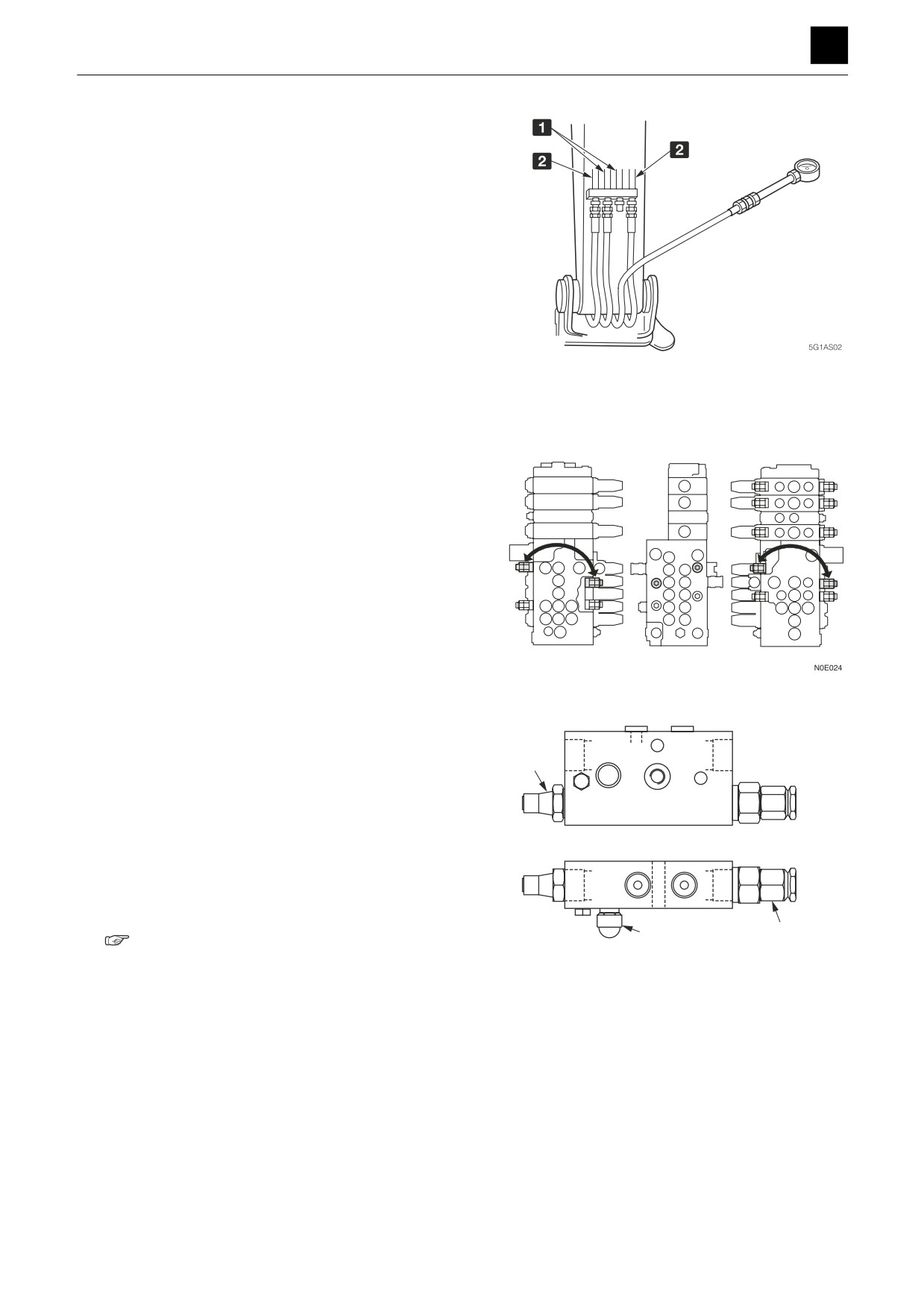
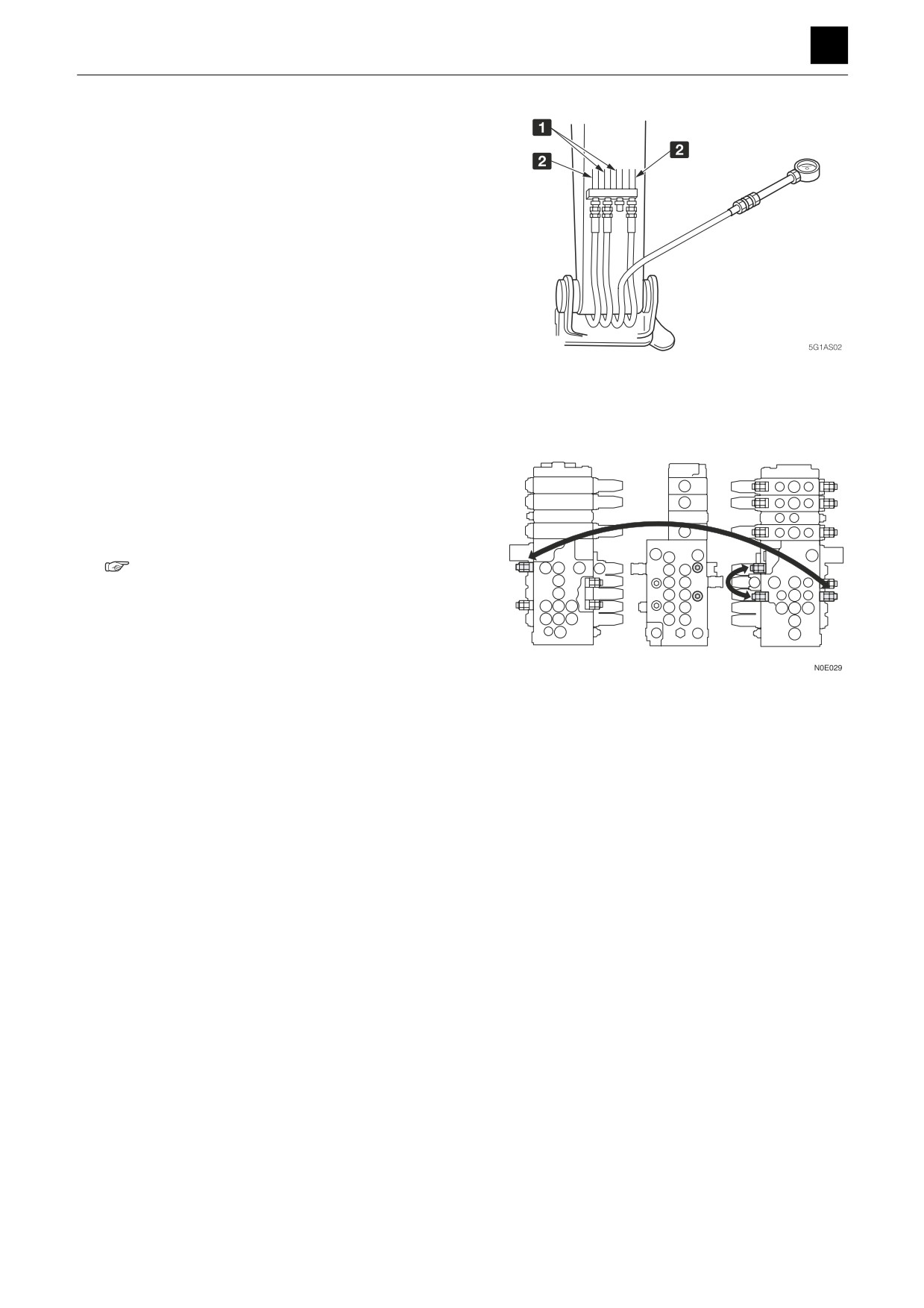
3. Check the control valve.
Disconnect the hose connecting the control valve
and arm cylinder from the pipe, and attach a pres-
sure gauge to the disconnected hose.
• Operate the lever (arm), and measure the pres-
sure.
Supply pressure: 34.3 MPa (4975 psi)
If the measured pressure is abnormal, replace the
control valve.
1 Arm
2 Bucket
4. Test the port relief valve with a replacement valve.
If the arm cylinder is able to operate with a replace-
ment valve taken out from a normal port relief valve
of the boom, then the port relief valve on the arm side
is faulty.
5. Check the emergency shut-off valve.
M
• Check it in the cylinder extension direction.
C2
a. Disconnect the hose from the emergency shut-off
E
V2
valve (PIL port), and attach a pressure gauge to
the hose.
Pil
T
b. Operate the lever (arm), and measure the pres-
sure.
c. The emergency shut-off valve is defective if the
pressure varies between 0 MPa and 3.9 MPa (0
M
C2
T
psi and 566 psi), according to the lever angle.
V2
6. Check the arm cylinder.
2
1
“4. Disassembly and assembly, Cylinder”
5G0AQ04Z
2
ARM
5G1AS00
TROUBLESHOOTING
ARM 5
Arm cylinder is slow or lacks force.
Within spec
Is the speed of the arm
1
Normal
cylinder within spec?
Out-of-spec
Faulty
Repair or replace the pilot
2
Check the pilot valve.
valve.
Normal
Faulty
Repair or replace the housing
3
Check the control valve.
block.
Normal
Faulty
Repair or replace the arm cyl-
4
Check the arm cylinder.
inder.
1. Is the speed of the arm cylinder within spec?
“2. Service data, Performance criteria”
2. Check the pilot valve.
“Arm, Arm cylinder does not move.”
3. Check the control valve.
“Arm, Arm cylinder does not move.”
3
ARM
5G1AS00
TROUBLESHOOTING
ARM 5
4. Check the arm cylinder.
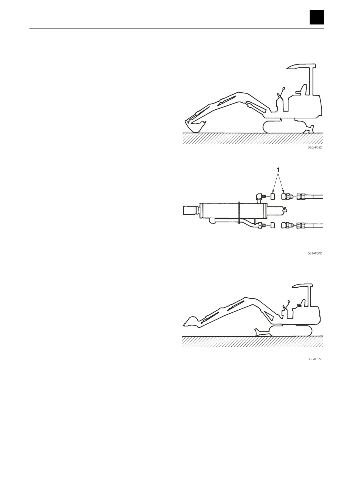
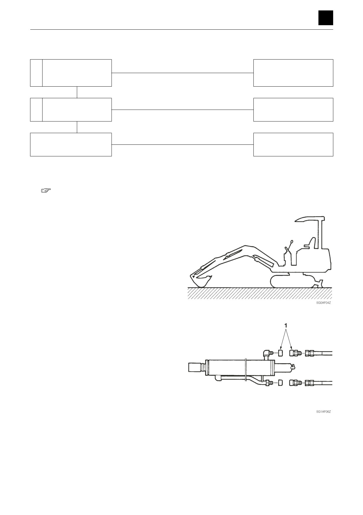
Check for leakage inside the arm cylinder.
a. Fully retract the arm cylinder and rest the bucket
on the ground.
b. Disconnect the two hoses from the cylinder. Insert
plugs (1) into the disconnected hoses and the cyl-
inder piping.
c. Raise the boom and lift the hoe attachment off the
ground. If the arm falls, the cylinder is faulty. If not,
internal leakage has is occurring inside the con-
trol valve.
4
ARM
5G1AS00
TROUBLESHOOTING
ARM 5
Spontaneous drop of the arm is too large.
Is the spontaneous drop
Within spec
1
of the arm cylinder within
Normal
spec?
Out-of-spec
Faulty
Repair or replace the arm cyl-
2
Check the arm cylinder.
inder.
Normal
3
Check the control valve.
Replace the housing block.
1. Is the spontaneous drop of the arm cylinder within
spec?
“2. Service data, Performance criteria”
2. Check the arm cylinder.
“Arm, Arm cylinder is slow or lacks force.”
3. Check the control valve.
“Arm, Arm cylinder does not move.”
5
ARM
5G1AS00
TROUBLESHOOTING
5
BUCKET
BUCKET
Bucket cylinder does not move or lacks force.
Check the operation of
Abnormal
Check the main relief valve
1
actuators other than the
and pump.
bucket cylinders.
Normal
Faulty
Repair or replace the pilot
2
Check the pilot valve.
valve.
Normal
Faulty
3
Check the control valve.
Repair or replace.
Normal
Problem solved
Test the port relief valve
The port relief valve is
Repair or replace the port re-
4
with a replacement valve.
faulty.
lief valve.
No change
Faulty
Check the bucket cylin-
Repair or replace the bucket
5
der.
cylinder.
1. Check the operation of actuators other than the buck-
et cylinder.
• Check whether only the bucket operation is faulty.
If the operation of other actuators is also defective,
see Overall Machine.
2. Check the pilot valve.
Disconnect the hose between the pilot valve and
control valve (Pa7, Pb7) from one of the valves, and
attach a pressure gauge to the disconnected hose.
• Fit the pressure gauge to the section indicated by
the arrow.
• Operate the lever
(bucket), and measure the
pressure.
• The pilot valve is working normally if the pressure
varies between 0 MPa and 3.9 MPa (0 and 566
psi), according to the lever angle.
If the measured pressure is abnormal, replace the pi-
5G2AS01
lot valve.
“Boom, Boom cylinder does not move.”
1
BUCKET
5G2AS00
TROUBLESHOOTING
5
BUCKET
3. Check the control valve.
Disconnect the hose connecting the control valve
and bucket cylinder from the pipe, and attach a pres-
sure gauge to the disconnected hose.
• Operate the lever
(bucket), and measure the
pressure.
Supply pressure: 34.3 MPa (4975 psi)
If the measured pressure is abnormal, replace the
control valve.
1 Arm
2 Bucket
4. Test the port relief valve with a replacement valve.
If the bucket cylinder is able to operate with a re-
placement valve taken out from a normal port relief
valve of the arm, then the port relief valve on the
bucket side is faulty.
5. Check the bucket cylinder.
“4. Disassembly and assembly, Cylinder”
2
BUCKET
5G2AS00
TROUBLESHOOTING
5
BUCKET
Spontaneous drop of the bucket is too large.
Is the spontaneous drop
Within spec
1
of the bucket cylinder
Normal
within spec?
Out-of-spec
Faulty
Check for leakage inside
Repair or replace the bucket
2
the bucket cylinder.
cylinder.
Normal
Oil leaking inside the control
Replace the housing block.
valve.
1. Is the spontaneous drop of the bucket cylinder within
spec?
“2. Service data, Performance criteria”
2. Check the bucket cylinder.
a. Fully extend the bucket cylinder, fully retract the
arm cylinder, and rest the bucket on the ground.
b. Disconnect the two hoses from the cylinder. Insert
plugs (1) into the disconnected hoses and the cyl-
inder piping.
c. Raise the boom and lift the hoe attachment off the
ground. If the bucket drops, the cylinder is faulty.
Otherwise, there is a leak inside the control valve.
3
BUCKET
5G2AS00
TROUBLESHOOTING
BOOM SWING 5
BOOM SWING
Swing cylinder does not move.
Check the operation of
1
actuators other than the
swing cylinder.
Normal
Faulty
Repair or replace the pilot
2
Check the pilot valve.
valve.
Normal
Faulty
Repair or replace the housing
3
Check the control valve.
block.
Normal
Problem solved
Test the port relief valve
The port relief valve is
Repair or replace the port re-
4
with a replacement valve.
faulty.
lief valve.
No change
Faulty
Check the swing cylin-
Repair or replace the swing
5
der.
cylinder.
1. Use the table to check whether only the boom swing
cylinder operation is faulty. If the operation is faulty,
check the main relief valve and the hydraulic pump
(main).
“2. Service data, Performance criteria”
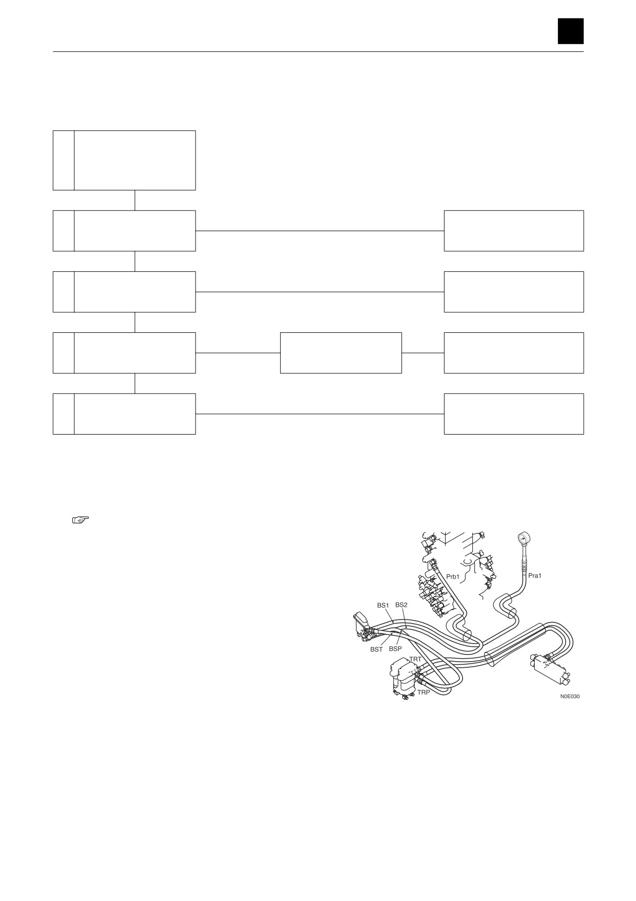
2. Check the pilot valve.
Disconnect the hose between the pilot valve and
control valve (Pra1, Prb1) from the control valve, and
attach a pressure gauge to the disconnected hose.
• Operate the pilot valve (boom swing), and mea-
sure the pressure.
• The pilot valve is working normally if the pressure
varies between 0 MPa and 3.9 MPa (0 and 566
psi), according to the lever angle.
1
BOOM SWING
5G3AS00
TROUBLESHOOTING
BOOM SWING 5
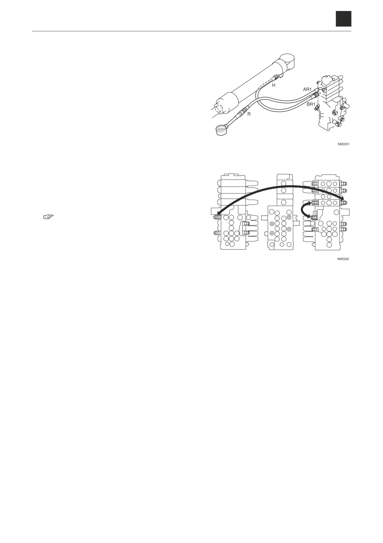
3. Check the control valve.
Disconnect the hose connecting the control valve
(AR1, BR1) and swing cylinder (R, H) from the cylin-
der end, and attach a pressure gauge to the discon-
nected hose.
• Operate the lever (boom swing), and measure the
pressure.
Supply pressure: 17 MPa (2465psi)
4. Test the port relief valve with a replacement valve.
If the boom swing cylinder is able to operate with a
replacement valve taken out from a port relief valve
of the normal arm, then the port relief valve on the
boom swing side is faulty.
5. Check the swing cylinder
“4. Disassembly and assembly, Cylinders”
2
BOOM SWING
5G3AS001
TROUBLESHOOTING
5
BLADE
BLADE
Blade cylinder does not move or lacks force.
Check the operation of
1
actuators other than the
blade cylinder.
Normal
Faulty
Repair or replace the pilot
2
Check the pilot valve.
valve.
Normal
Faulty
3
Check the control valve.
Repair or replace.
Normal
Problem solved
Test the port relief valve
The port relief valve is
Repair or replace the port re-
4
with a replacement valve.
faulty.
lief valve.
No change
Faulty
5
Check the swivel joint.
Repair or replace.
Normal
Faulty
Repair or replace the blade
Check the blade cylinder.
cylinder.
1. Use the table to check whether only the blade cylin-
der operation is faulty. If the blade cylinder is faulty,
check the main relief valve and the hydraulic pump.
“2. Service data, Performance criteria”
Lever to operate
Device to check
2nd auxiliary line
Relief valve R3
Pump Pr
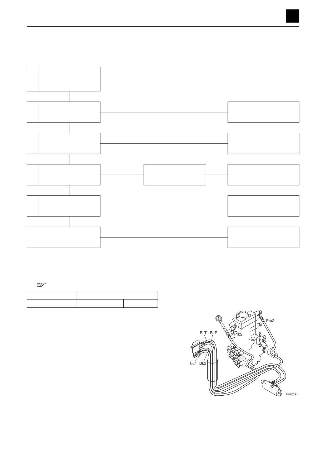
2. Check the pilot valve.
Disconnect the hose between the pilot valve (blade)
and control valve (Pra2, Prb2) from the control valve,
and attach a pressure gauge to the disconnected
hose.
• Operate the pilot valve (blade), and measure the
pressure.
• The pilot valve is working normally if the pressure
varies between 0 MPa and 3.9 MPa (0 and 566
psi), according to the lever angle.
1
BLADE
5G5AS00
TROUBLESHOOTING
5
BLADE
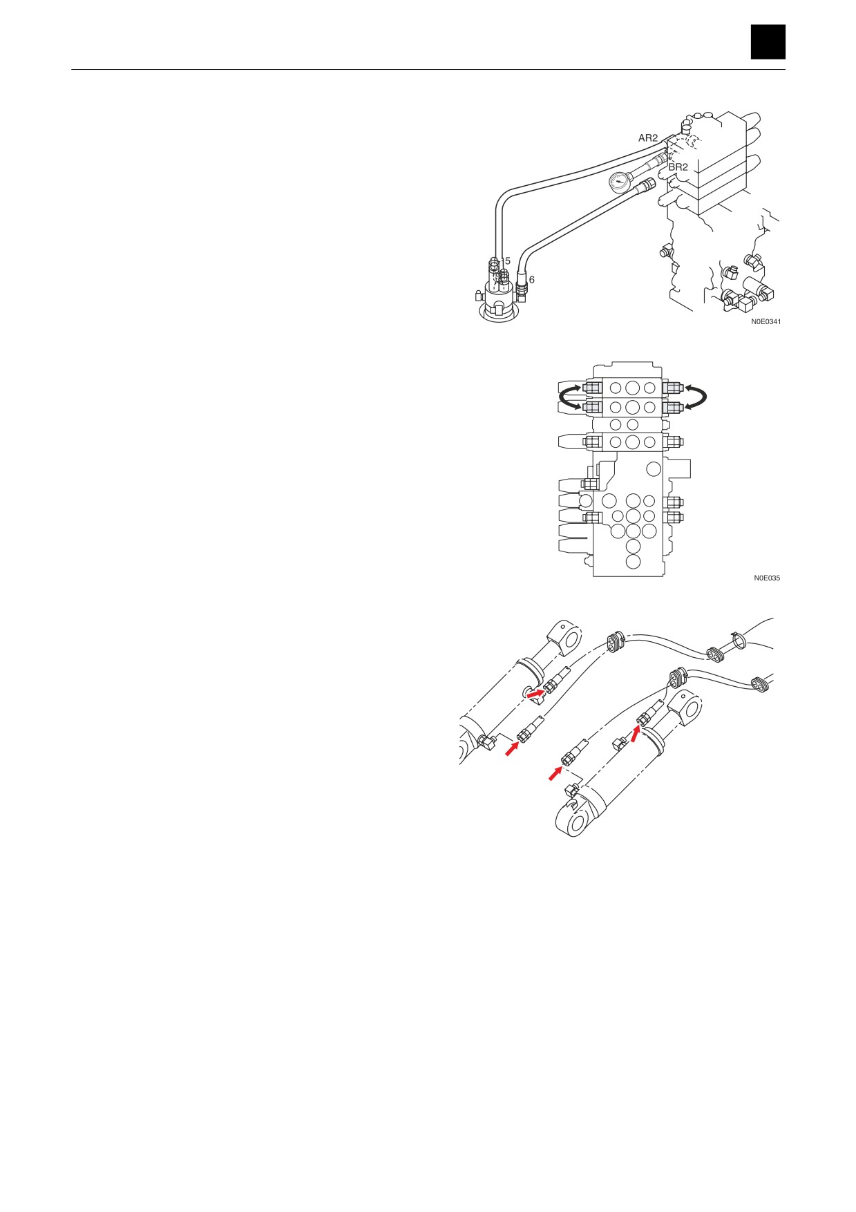
3. Check the control valve.
Disconnect the hose connecting the control valve
(blade section) and swivel joint from the control valve
(AR2, BR2), and attach a pressure gauge to the port
of the control valve.
• Operate the pilot valve (blade), and measure the
pressure.
Supply pressure: 23.6 MPa (3423 psi)
4. Test the port relief valve with a replacement valve.
If the blade is able to operate with a replacement
valve taken out from a normal port relief valve of the
2nd auxiliary line, then the port relief valve on the
blade side is faulty.
After the above check is complete, return the port re-
lief valve to its prescribed position.
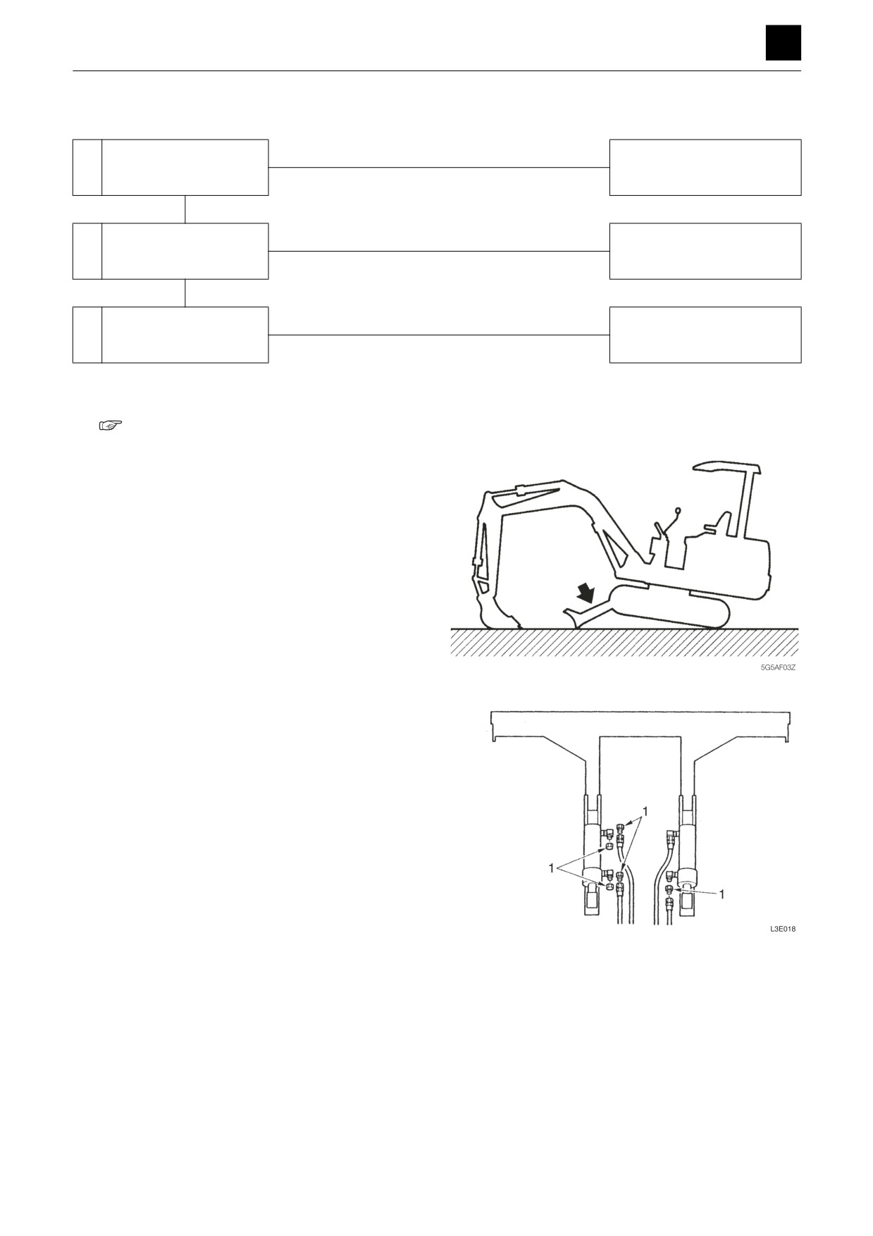
5. Check the swivel joint.
Disconnect the hose connecting the swivel joint and
blade cylinder from the cylinder. Attach a pressure
gauge to the disconnected hose.
• Fit the pressure gauge to the section indicated by
the arrow.
• Operate the pilot valve (blade), and measure the
pressure.
• The swivel joint is faulty if the measured value list-
ed below is not achieved.
Supply pressure: 23.6 MPa (3423 psi)
5G5AS01
2
BLADE
5G5AS00
TROUBLESHOOTING
5
BLADE
The spontaneous drop of the blade is too large, or the blade cannot support the machine.
Within spec
Is the spontaneous drop
1
Normal
of the blade within spec?
Out-of-spec
Faulty
Check for leakage inside
Repair or replace the housing
2
the blade cylinder.
block.
Normal
Faulty
Check the swivel joint
Repair or replace the swivel
3
and control valve.
joint or control valve.
1. Is the spontaneous drop of the blade within spec?
“2. Service data, Performance criteria”
2. Check for leakage inside the blade cylinder.
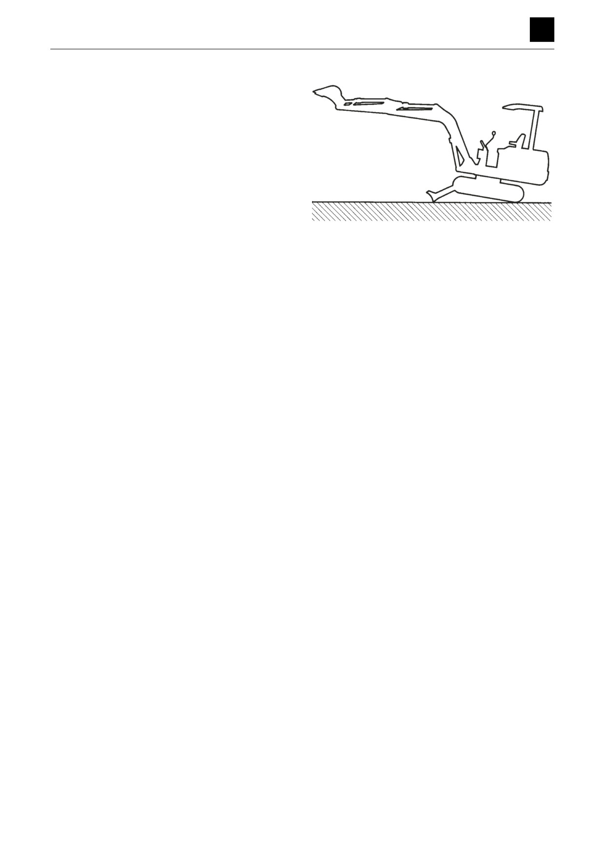
a. Raise the machine using the hoe attachment, and
fully lower the blade.
b. Disconnect the hose from the rod end of the blade
cylinder (right), and drain oil from the hose.
Insert a plug (1) into the disconnected hose.
• Remove the two hoses from the blade cylinder
(left) not being checked, and insert plugs (1) into
the disconnected ports and hoses.
• After checking the cylinder of the blade cylinder
(right), check the blade cylinder (left).
3
BLADE
5G5AS00
TROUBLESHOOTING
5
BLADE
c. Raise the boom to apply a load to the blade.
• If the machine drops while the oil drains from
the cylinder piping, the cylinder is faulty.
If the machine drops even though no oil drains
out, the control valve or the swivel joint is faulty.
If the machine cannot be supported by the
blade, replace the port relief valve with a nor-
mal valve. If the blade can now support the ma-
chine, the port relief valve was faulty.
5G5AF05Z
3. Check the swivel joint and control valve.
Disconnect the control valve end of the hose con-
necting the swivel joint and control valve. Insert a
plug in the disconnected hose.
Follow the procedure in item 2 a to c above to apply
a load to the blade.
If the machine drops, the swivel joint is faulty.
If the machine does not drop, oil is leaking inside the
control valve.
4
BLADE
5G5AS00
TROUBLESHOOTING
5
AUXILIARY HYDRAULICS
AUXILIARY HYDRAULICS
Prescribed pressure is not supplied to the 1st and 2nd auxiliary lines.
Check the operation of
1
actuators other than the
auxiliary line.
Normal
Check the voltage sup-
Faulty
2
plied to the proportional
Repair or replace.
control solenoid valve.
Normal
Faulty
Check the proportional
3
Repair or replace.
control solenoid valve.
Normal
Faulty
Repair or replace the housing
4
Check the control valve.
block.
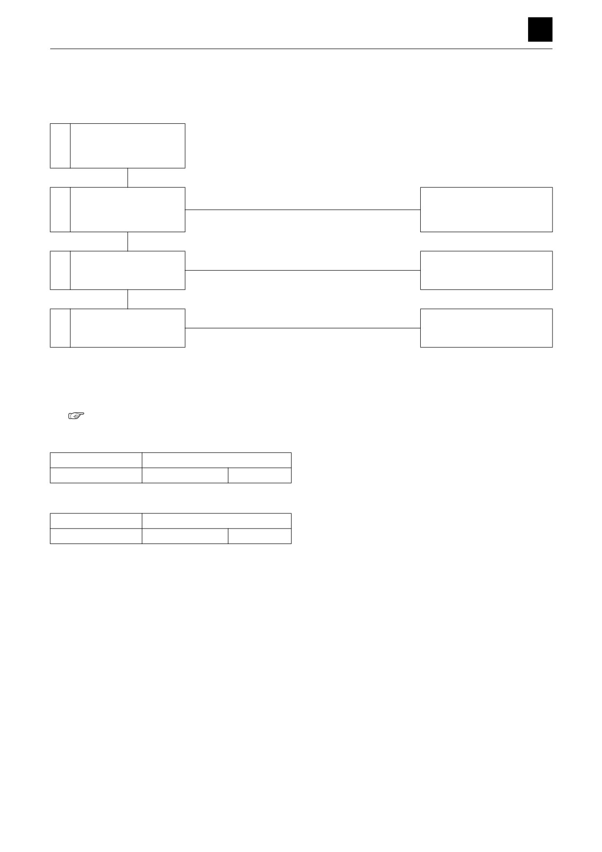
1. Use the table to check whether only the auxiliary line
operation is faulty. If operation is faulty, check the
main relief valve and the hydraulic pump.
“2. Service data, Performance criteria”
1st auxiliary line
Lever to operate
Device to check
Right travel
Relief valve R1
Pump P1
2nd auxiliary line
Lever to operate
Device to check
Dozer blade
Relief valve R3
Pump P4
1
AUXILIARY HYDRAULICS
5G6AS00
TROUBLESHOOTING
5
AUXILIARY HYDRAULICS
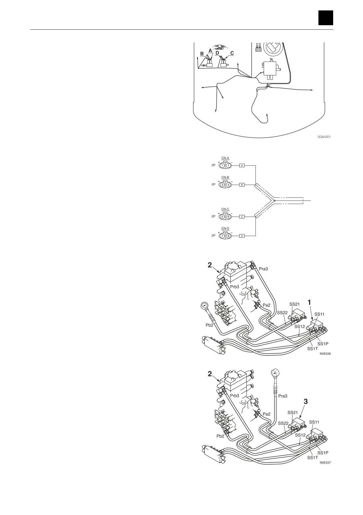
2. Check the voltage supplied to the proportional control
solenoid valve.
Operate the pilot valve proportional lever, and check
the voltage supplied to the proportional control sole-
noid valve from the proportional amplifier.
<1st auxiliary line>
• Terminals (1) and (2), Marking A
• Terminals (3) and (4), Marking B
24 V is normal.
<2nd auxiliary line>
• Terminals (5) and (6), Marking C
• Terminals (7) and (8), Marking D
24 V is normal.
5G6AS02
3. Check the proportional control solenoid valve.
<1st auxiliary line>
Disconnect the hose between the proportional con-
trol solenoid valve (1) and control valve (2), (Pa3,
Pb3) from the control valve, and attach a pressure
gauge to the disconnected hose.
• Operate the proportional lever for the pilot valve,
and measure the pressure.
• The pilot valve is working normally if the pressure
varies between 0 MPa and 3.9 MPa (0 and 566
psi), according to the lever angle.
<2nd auxiliary line>
Disconnect the hose between the proportional con-
trol solenoid valve (3) and control valve (Pra3, Prb3)
from the control valve, and attach a pressure gauge
to the disconnected hose.
• Operate the proportional lever for the pilot valve,
and measure the pressure.
• The pilot valve is working normally if the pressure
varies between 0 MPa and 3.9 MPa (0 and 566
psi), according to the lever angle.
2
AUXILIARY HYDRAULICS
5G6AS00
TROUBLESHOOTING
5
AUXILIARY HYDRAULICS
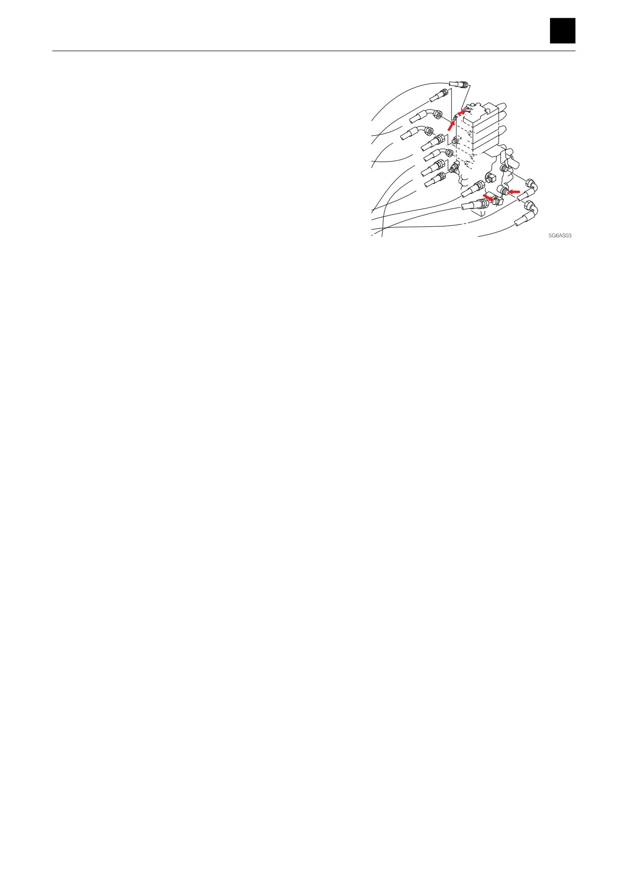
4. Check the control valve.
AR3
<1st auxiliary line>
BR3
Disconnect the auxiliary line hose from the control
valve (A2, B2), and attach a pressure gauge to the
AR1
port on the control valve.
A8
• Operate the proportional lever for the pilot valve,
BR1
and measure the pressure.
A7
• Supply pressure: 34.3 MPa (4975 psi)
B8
B5
A5
B7
<2nd auxiliary line>
A2
B2
Disconnect the auxiliary line hose from the control
valve, and attach a pressure gauge to the port on the
control valve (AR3, BR3).
• Operate the proportional lever for the pilot valve,
and measure the pressure.
• Supply pressure: 34.3 MPa (4975 psi)
3
AUXILIARY HYDRAULICS
5G6AS00
TROUBLESHOOTING
5
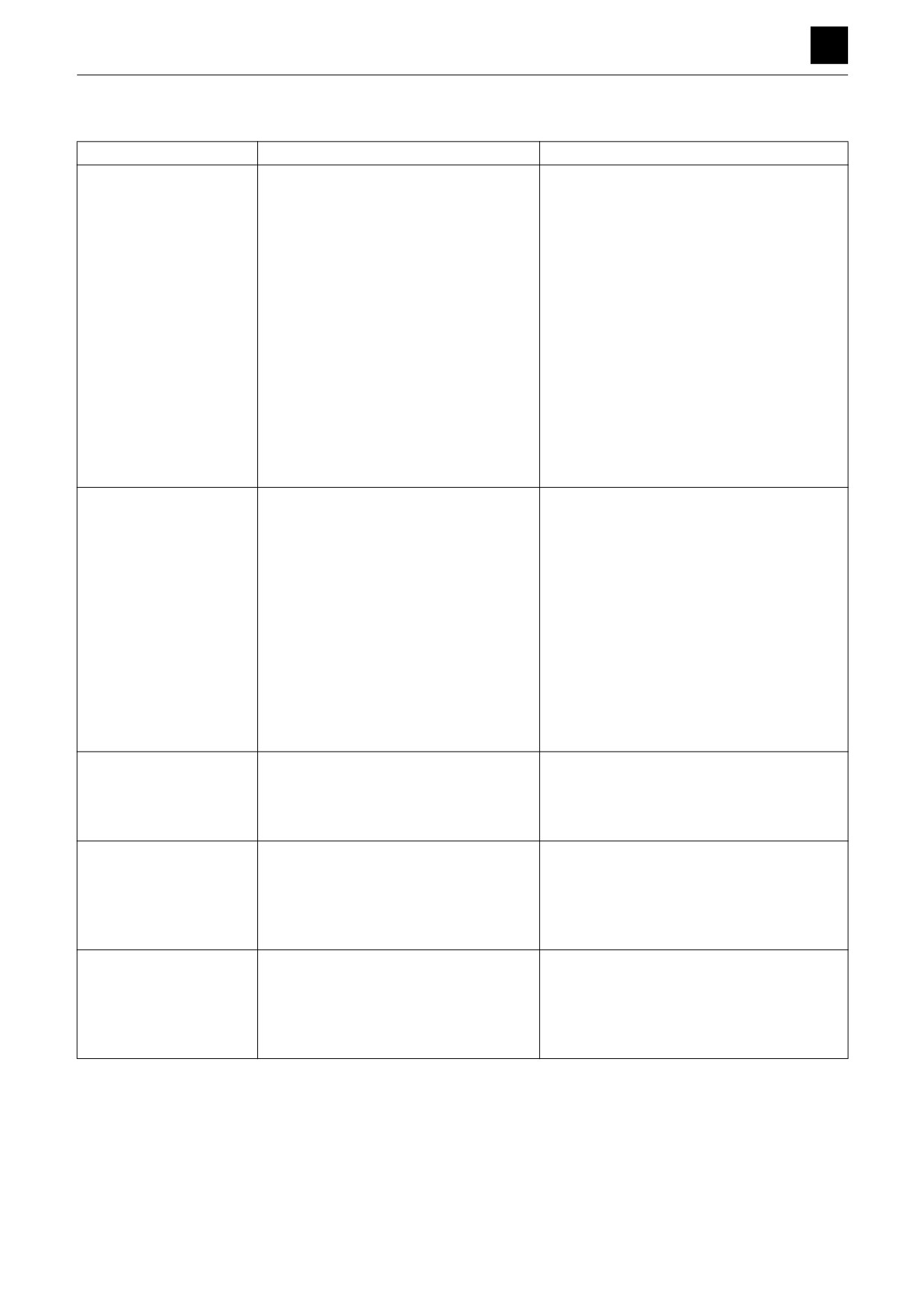
PISTON PUMP
PISTON PUMP
Symptoms
Major causes
Remedies
Noise is too loud, unusual
•
Suction hose is crushed or suction filter
•
Remove the dirt and correct the crushing.
sound is heard
is clogged.
•
Joint in the suction side is loose and
•
Retighten each joint.
sucking air.
•
Cavitation is being produced due to too
•
Replace with hydraulic oil of proper viscos-
high viscosity of the hydraulic oil.
ity.
•
Pump and engine are not center
•
Center them again.
aligned.
•
Frothing of hydraulic oil.
•
Investigate the cause of frothing and cor-
rect it.
•
Engine RPM is too high.
•
Run at the rated RPM.
•
Mechanical damage to the parts (e.g.,
•
Replace the damaged part(s) or the pump.
bearing).
•
The regulator is experiencing hunting
•
Repair the regulator.
oscillation.
Discharge is insufficient
•
Engine RPM is too low.
•
Run at the rated RPM.
•
Oil temperature is too high.
•
Stop running, and check the temperature
again after the oil cools down.
•
Viscosity of hydraulic oil is too high.
•
Replace with hydraulic oil of proper viscos-
ity.
•
Pump volume efficiency becomes low.
•
Replace the pump.
•
Hydraulic oil tank level is too low.
•
Add oil to the specified level.
•
Clogging in the suction piping or the
•
Clean the piping.
suction filter.
•
Leak volume of hydraulic devices other
•
Repair or replace the leaking hydraulic de-
than the pump is increased.
vice.
•
The regulator is faulty.
•
Repair the regulator.
Pressure is not increased
•
Set pressure for the relief valve drops.
•
Set the relief valve pressure again.
•
Leak volume of hydraulic devices other
•
Repair or replace the leaking hydraulic de-
than the pump is increased.
vice.
•
Pump volume efficiency becomes low.
•
Replace the pump.
Abnormal heat is generat-
•
Leak volume from the pump is in-
•
Replace the pump.
ed
creased.
•
Mechanical damage to the parts (e.g.,
•
Replace the damaged part(s) or the pump.
bearing).
•
Seizing on the sliding part.
•
Replace the damaged part(s) or the pump.
Oil leak
•
Seals are damaged.
•
Replace the seal(s).
•
Sliding part between the shaft and the
•
Replace the shaft or the pump.
oil seal is worn out.
•
Plugs and bolts are loosened.
•
Retighten the plugs and bolts, or replace
the seals.
1
PISTON PUMP
5I0AS00
TROUBLESHOOTING
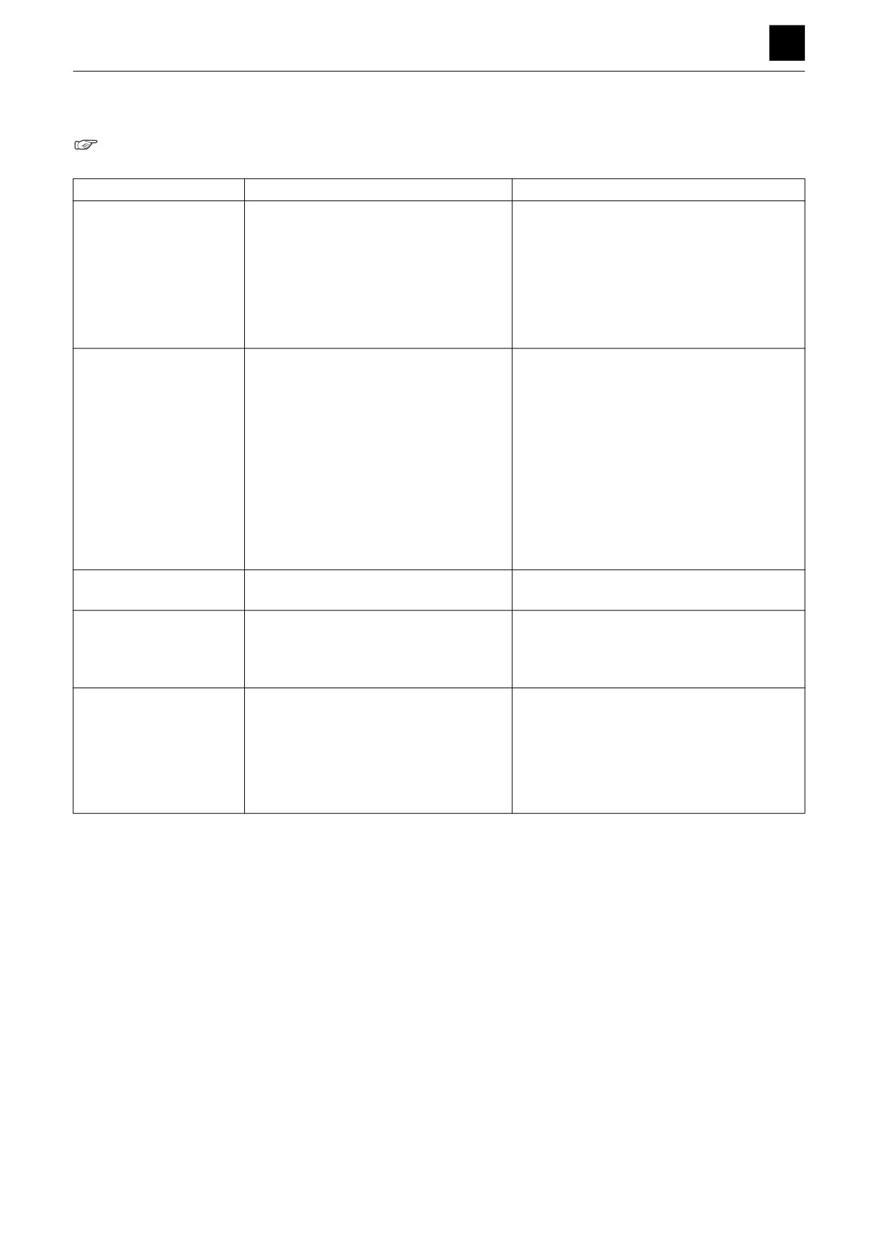
GEAR PUMP 5
GEAR PUMP
“4. Disassembly and assembly, Gear pump”
Symptoms
Major causes
Remedies
No discharging operation
•
Direction of rotation is incorrect.
•
Rotate in the rated direction.
•
Hydraulic oil tank level is too low.
•
Add oil to the specified level.
•
Clogging in the suction piping or the
•
Clean the piping.
suction filter.
•
Viscosity of hydraulic oil is too high.
•
Replace with hydraulic oil of proper viscos-
ity.
•
RPM is too low.
•
Run at the rated RPM.
Noise is too loud, unusual
•
Cavitation is being produced due to the
•
Remove the dirt and correct the crushing.
sound is heard
crushed hose or clogged filter of the
suction side.
•
Joint in the suction side is loose and
•
Retighten each joint.
sucking air.
•
Cavitation is being produced due to too
•
Replace with hydraulic oil of proper viscos-
high viscosity of the hydraulic oil.
ity.
•
Pump and engine are not center
•
Center them again.
aligned.
•
Frothing of hydraulic oil.
•
Investigate the cause of frothing and cor-
rect it.
•
Oil seal is deformed, worn out or dam-
•
Replace the oil seal.
Oil leak from the oil seal
aged.
Oil leak from the mating
•
Body seal is damaged, or the sliding
•
Replace with a new one.
surface between the
part is worn out.
housing and the flange or
housing and the cover
Discharge is insufficient
•
Bushing seal is damaged.
•
Replace the bushing seal.
•
Cavitation is being produced.
•
Clean the suction filter and the suction pip-
ing.
•
Aeration is being produced.
•
Check if piping is properly screwed in.
•
Viscosity of hydraulic oil is too low.
•
Replace with hydraulic oil of proper viscos-
ity.
1
GEAR PUMP
5I1AQ00
TROUBLESHOOTING
5
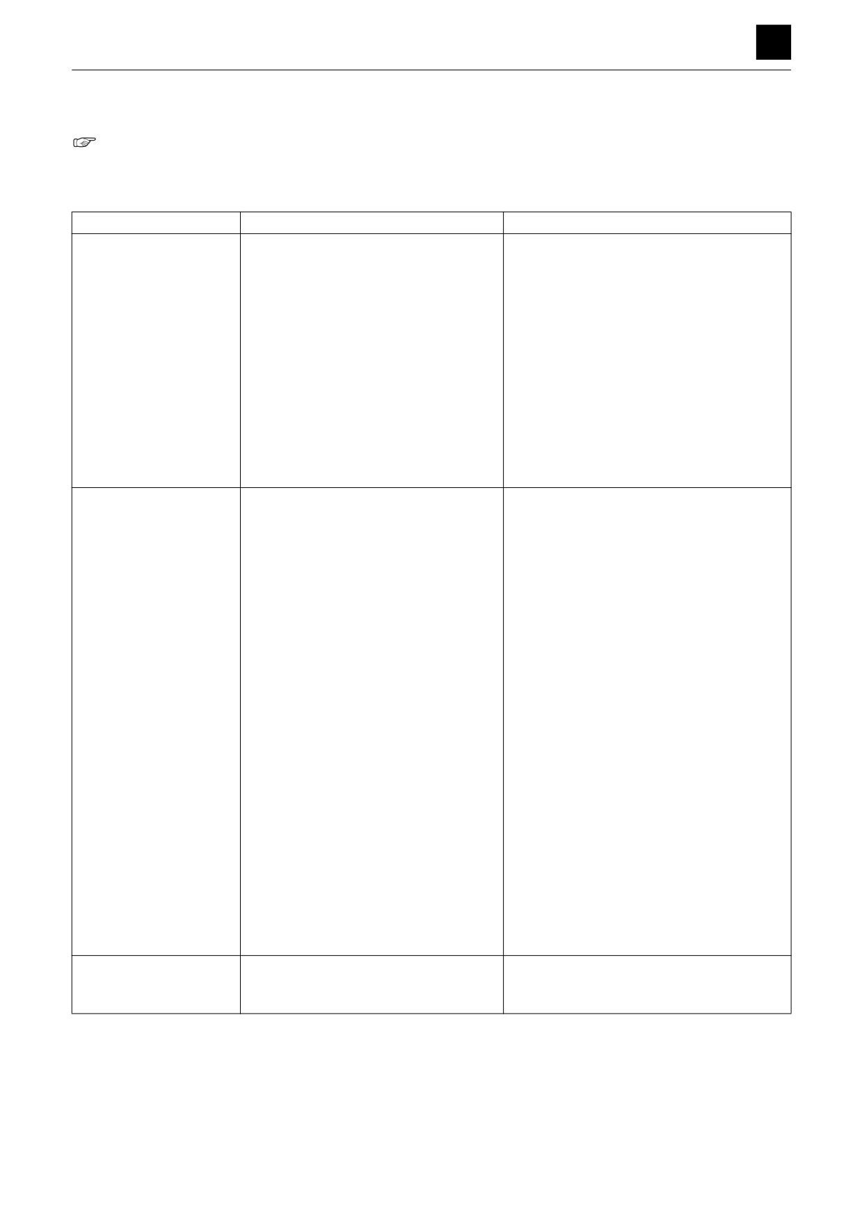
CONTROL VALVE
CONTROL VALVE
“4. Disassembly and assembly, Control valve”
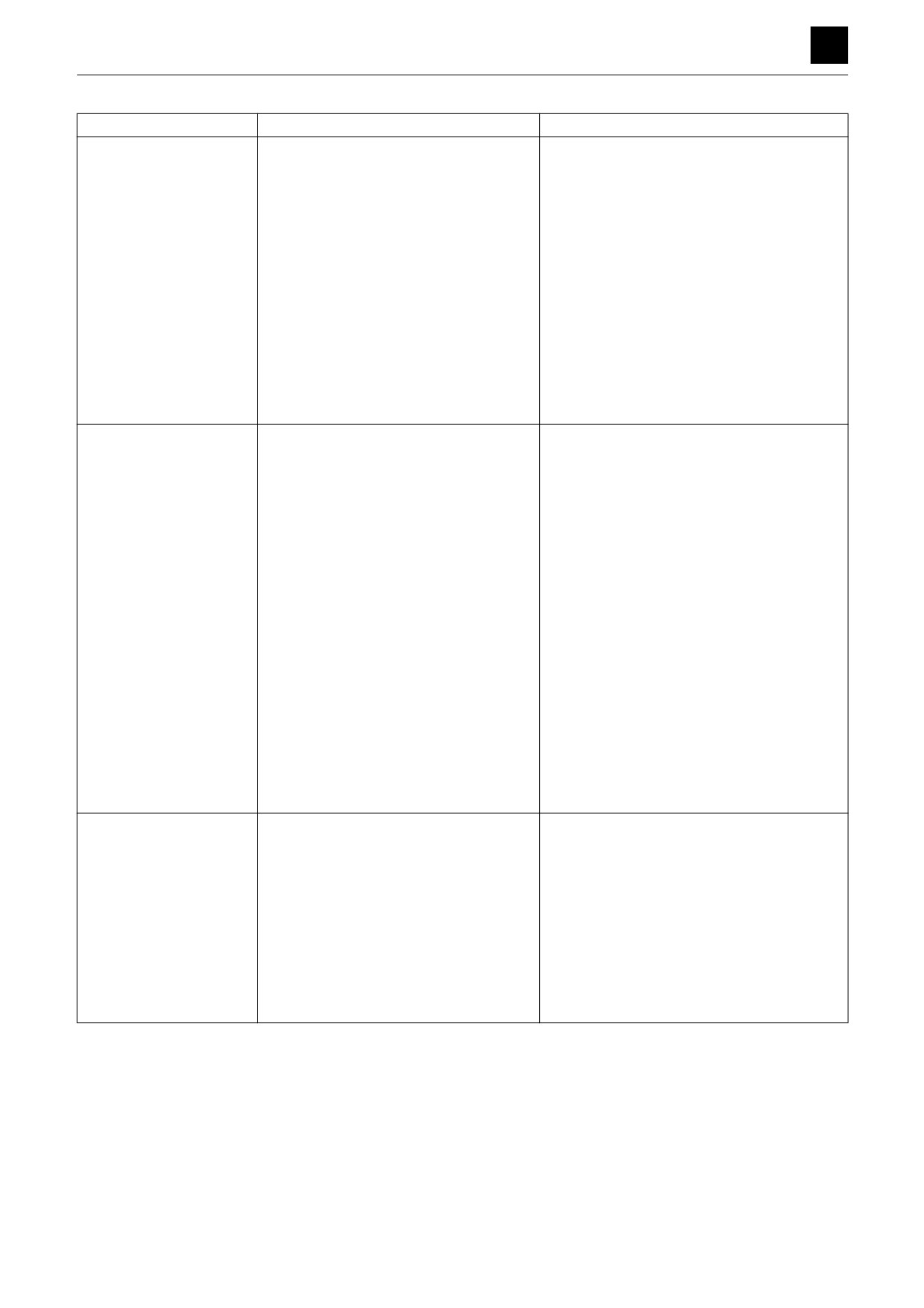
The problems are listed individually in the table below, but in reality, many problems have multiple causes. Therefore,
try to check and eliminate each possible cause one at a time.
Symptoms
Major causes
Remedies
Oil leak from the spool
•
Flaw is on the sealing part or the seal lip
•
Replace with a new one.
seal
is worn out due to prolonged use.
•
Flaw (e.g., dents or scratches) on the
•
Repair or replace the spool.
sliding part of the spool seal is caused
by an external factor.
•
The lid that is pushing the sealing parts
•
Correct the lid, and determine the partial
in place is installed improperly (lid is
wear degree of the seal.
distorted)
•
Old paint remains on the seal sliding
•
Remove it by using thinner or mechanical
part of the spool.
force. When removing, take care not to
damage the spool surface or the seal lip.
•
Tank pressure becomes too high for the
•
Remove the cause of the flow resistance.
performance of the sealing material.
Sliding part of the spool is
•
Foreign matter is caught in the sliding
•
Overhaul and repair or replace.
not smooth
part of the spool.
•
Oil film between the spool and the body
•
Try to decrease the oil temperature. If the
becomes too thin due to the increased
relief valve is started often, find the cause
oil temperature.
and correct it.
•
Lubrication is disabled due to deterio-
•
Oil should be replaced. The circuit also
rated oil.
should be overhauled in some cases.
•
Spool is worn out because of prolonged
•
Replace the spool and the valve block as-
use or of the unbalanced force applied.
sembly.
•
Spool is bent by the external force.
•
Check for the straightness of the spool, and
repair or replace.
•
Whole valve is distorted due to the dis-
•
Check the distortion, independent of the in-
tortion of the installation surface.
stallation surface (loosening the bolts will
help).
•
Valve is operated with the pressure or
•
For pressure, measure it with a pressure
the flow rate of out-of-spec.
gauge. For flow rate, determine it by finding
out the movement speed and capacity of
the actuator.
•
Fixing bolts are over-tightened.
•
Check if the fixing bolts are tightened with
the specified torque. If not, tighten them
again with the specified torque.
•
Oil stays in the lid (spring or detent) op-
•
Oil may come out from the lid, if it is leaking
posite to the spool operation.
in the seal of the spool. If that is the case,
replace the seal.
When the actuator is be-
•
Foreign matter is caught in the seat on
•
Disassemble the valve and overhaul or re-
ing raised, it drops once
the load check valve, or the seat is
place the faulty part(s).
damaged by large foreign matter.
1
CONTROL VALVE
5J0AQ00
TROUBLESHOOTING
5
CONTROL VALVE
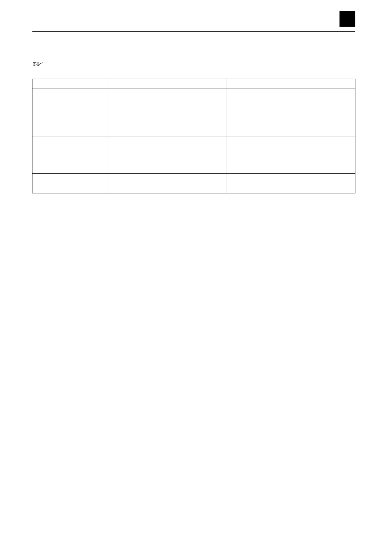
Symptoms
Major causes
Remedies
Spool’s neutral position
•
There are cases of a large oil leak in-
•
Check if the cylinder drops spontaneously
cannot be maintained
side the cylinder.
when it is held. If the cylinder is faulty, dis-
(cylinder drops)
assemble and repair it.
•
Since the clearance between the spool
•
Replace the spool and the valve block as-
and the body is too large, oil is leaking
sembly.
from the clearance.
•
Spool is not completely back in the neu-
•
Manual: Check if the link mechanism is in-
tral position.
terfering with others.
Hydraulic operation: Check the pilot pres-
sure.
•
Foreign matter is caught in the seat of
•
Disassemble, overhaul or replace.
the port relief valve or of the anti-cavita-
tion valve, and thus the oil is bypassing
the section. Or the seat is damaged.
Load cannot be moved
•
Foreign matter is caught in the seat of
•
Disassemble, overhaul or replace.
(pressure cannot be in-
the port relief valve, and thus the oil is
creased)
bypassing the section. Or the seat is
damaged.
•
Adjuster screw on the relief valve is
•
Screw in the adjuster screw. If loose, set the
loose.
adjustment again and fasten with a lock nut.
•
Foreign matter is caught in the seat of
•
Disassemble, overhaul or replace.
the port relief valve or of the anti-cavita-
tion valve, and thus the oil is bypassing
the section. Or the seat is damaged.
•
Spool stroke is out-of-spec.
•
Manual: Check if the link mechanism is in-
terfering with others. Check if the pin or pin
hole on the linking section is worn out.
•
Oil supply from the pump is insufficient,
•
Hydraulic operation: Check the pilot pres-
because the pump is damaged.
sure.
Check for any abnormality in the pump.
If the pump is faulty, replace it and find the
cause of the abnormality (e.g., faulty air
sucking or oil degradation).
Load cannot be moved
•
Overloading
•
Compare with a one with standard load.
(pressure is being in-
•
Mechanical resistance of related parts/
•
Check and add oil, modify or repair the
creased)
devices
(unrelated to the hydraulic
parts/devices.
pressure of the hydraulic oil) is large.
•
Large resistance is generated, be-
•
Repair if the location of clogging or bent is
cause the circuit is clogged with large
known.
foreign matter or the piping is bent.
•
Spool stroke is out-of-spec.
•
Check if the link mechanism is interfering
with others and if the pin or pin hole on the
linking section is worn out.
2
CONTROL VALVE
5J0AQ00
TROUBLESHOOTING
5
PILOT VALVE
PILOT VALVE
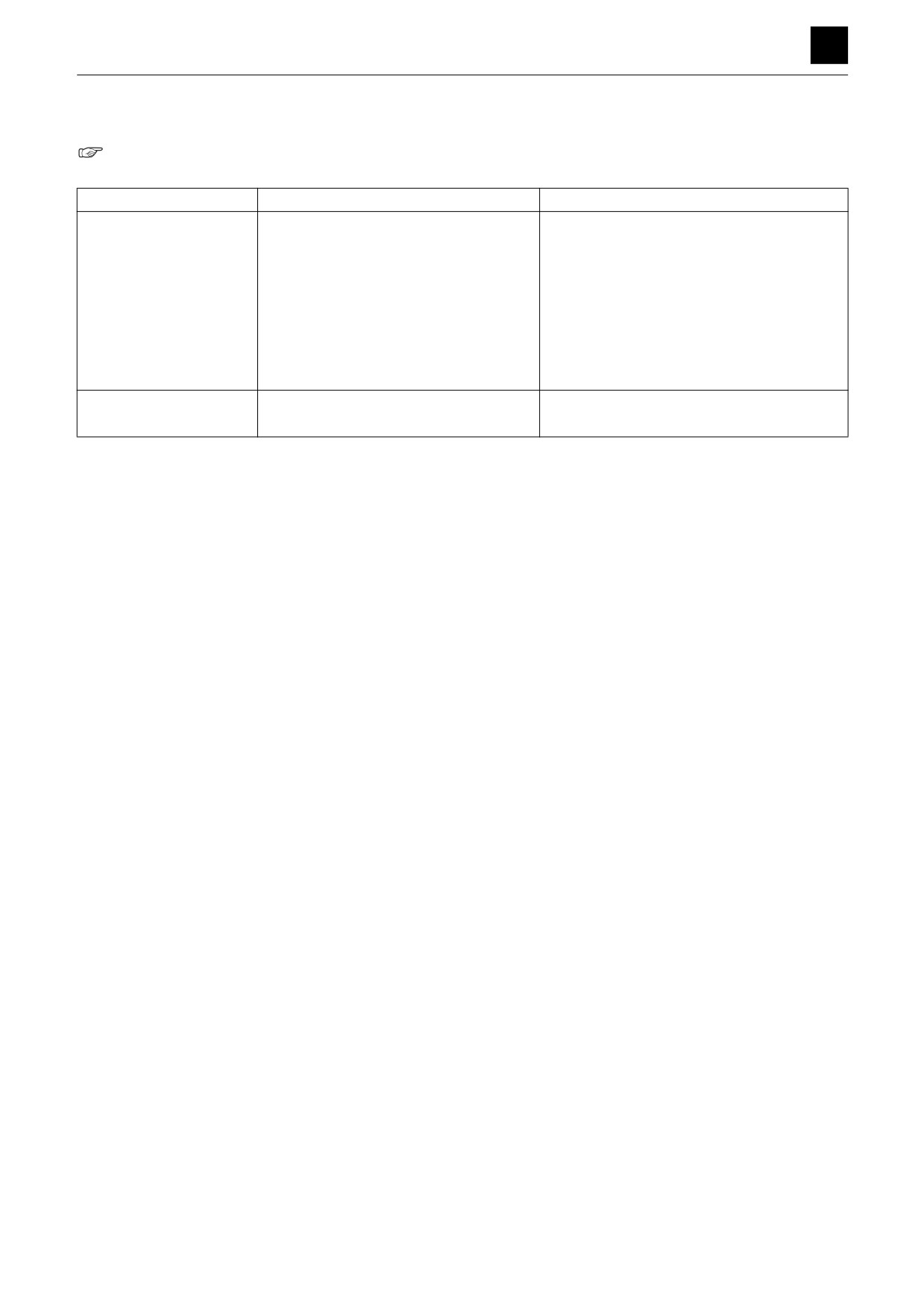
“4. Disassembly and assembly, Pilot valve”
Symptoms
Major causes
Remedies
The secondary pressure
• Primary pressure is insufficient.
• Keep the primary pressure.
is too low
• The spring is broken or worn out.
• Replace
• The clearance between the spool and
• Replace the spool and the casing assem-
the casing is too large.
bly.
• Too much play in the handle.
• Disassemble and assemble or replace.
The secondary pressure
• The sliding part is not smooth.
• Repair or replace.
is unstable
• The tank line pressure fluctuates.
• Remove the faulty part(s) in the tank line.
• Air is present in the piping.
• Bleed air by operating the valve several
times.
The secondary pressure
• Pressure in the tank line is high.
• Remove the faulty part(s) in the tank line.
is high
• The sliding part is not smooth.
• Repair or replace.
1
PILOT VALVE
5K2AQ00
TROUBLESHOOTING
5
SOLENOID VALVE
SOLENOID VALVE
“4. Disassembly and assembly, solenoid valve”
Symptoms
Major causes
Remedies
Solenoid valve does not
• Wiring short-circuit or wire break.
• Replace
operate
• Coil assembly short-circuit or wire
• Replace
break.
• Foreign matter is caught in the spool.
• Overhaul and repair or replace.
• Damage on the outer circumference of
• Overhaul and repair or replace.
the spool.
• Proportional controller is faulty.
• Repair or replace.
• Primary pressure is insufficient.
• Keep the primary pressure.
Oil leakage from solenoid
• O-ring is damaged.
• Replace
valve
• Seal nut is damaged.
• Replace
1
SOLENOID VALVE
5K6AQ00