Takeuchi Hydraulic excavator TB1140 (Serial No. 514400002~). Operator's Manual - page 10
DISASSEMBLY AND ASSEMBLY
SLEW MOTOR 4
Assembly
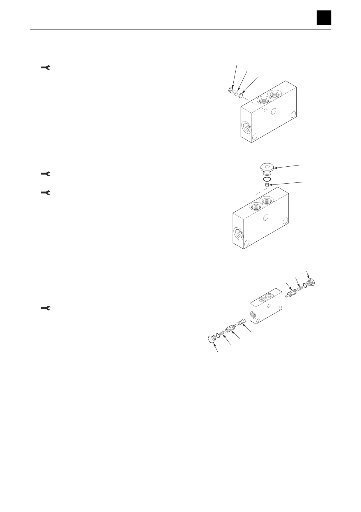
Reversal prevention valve
1. Insert the filter (9), washer (8), and orifice (7).
7
Orifice: 4.9 N·m ± 1 N·m
8
9
G4D615
2. Insert the orifice (6).
5
Orifice: 2.45 N·m ± 0.49 N·m
6
3. Insert the plug (5) with attached O-ring.
Orifice: 61.8 N·m ± 2.9 N·m
G4D614
1
4. Insert the sleeve (4).
2
5. Insert the check valve assembly (3) and the spring
3
(2).
6. Insert the plug (1) with attached O-ring.
Plug: 61.8 N·m ± 2.9 N·m
4
3
2
1
G4D613
17
SLEW MOTOR
4N0AS00
DISASSEMBLY AND ASSEMBLY
SLEW MOTOR 4
Brake valve and hydraulic motor
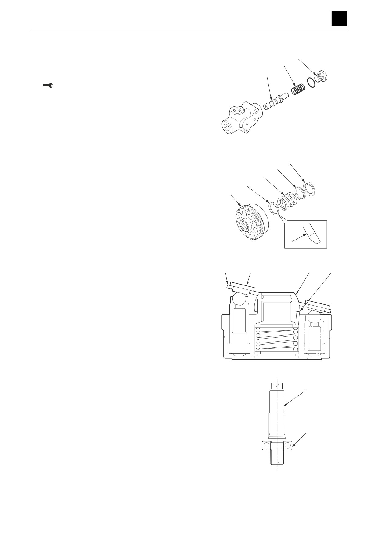
1. Assemble the timer valve.
31
• Be careful not to damage attachment surfaces.
32
a. Insert the spool (33) and the spring (32).
33
b. Insert the plug (31) with attached O-ring.
Plug: 39.2 N·m ± 2.0 N·m
K3D644
24
2. Insert the washer (27), spring (26), washer (25), and
25
snap ring (24) into the cylinder block.
26
• Attach the washer (27) with the surface (A) on the
27
cylinder block side.
18
A
E5D622
3. Insert the pin (23) into the cylinder block.
• Grease the pin.
4. Insert the guide (22).
5. Insert the shoe holder (14) into the piston assembly
(21), and insert the shoe holder (14) and piston as-
sembly (21) into the cylinder block.
• Apply enough hydraulic oil to the parts before in-
serting them.
6. Insert the bearing (30) into the shaft (29).
29
• Press-fit the bearing into the shaft using the press-
fitting jig (E).
30
K3D643
18
SLEW MOTOR
4N0AS00
DISASSEMBLY AND ASSEMBLY
SLEW MOTOR 4
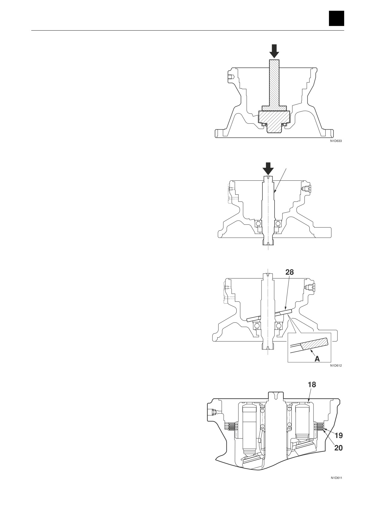
7. Insert the oil seal into the case.
• Grease the oil seal.
• Use the press-fitting jig (K) to push the oil seal all
the way into the case.
8. Insert the pinion shaft (29) into the motor housing.
• Press-fit the pinion shaft into the motor housing
using the press-fitting jig (F).
9. Attach the swash plate (28) to the motor housing.
• Grease side A.
10. Attach the cylinder block (6) to the housing.
• When attaching, be careful not to allow the pins
and shoe holder to come loose from the cylinder
block.
11. Insert the center discs (20) and the friction discs
(19).
• Line up the positions of the gaps in the spline
teeth.
19
SLEW MOTOR
4N0AS00
DISASSEMBLY AND ASSEMBLY
SLEW MOTOR 4
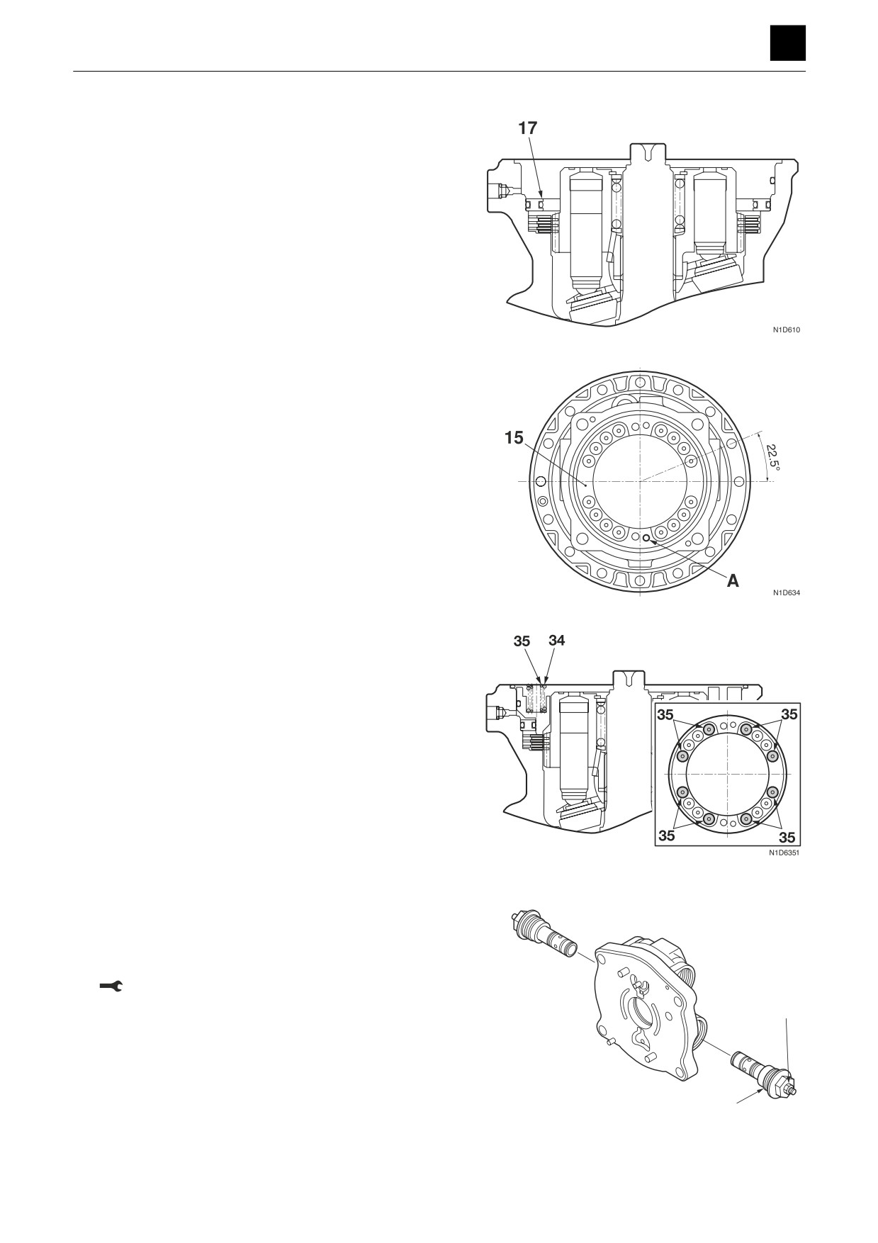
12. Insert the collar (17) with attached O-rings.
13. Insert the brake pistons (15) with attached O-rings
into the motor housing.
• Insert the brake pistons so that position (A) for the
6.4-mm-diameter pin hole is at the position in the
diagram at right.
• Press-fit the brake piston using the press ma-
chine.
14. Insert the sixteen large springs (34), the eight small
springs (35), and the O-rings.
• Insert the eight small springs (35) into the loca-
tions indicated in the diagram at right.
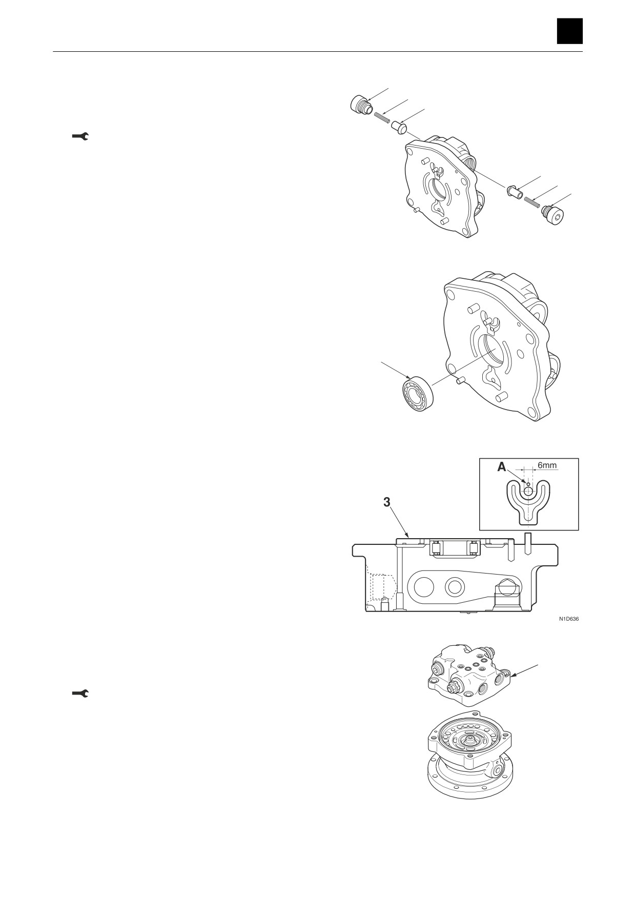
15. Attach the O-ring and backup ring to the relief valve
(12).
16. Insert the relief valve into the cover.
• Do not loosen the set screw (13).
Plug: 373 N·m ± 20 N·m
20
SLEW MOTOR
4N0AS00
DISASSEMBLY AND ASSEMBLY
SLEW MOTOR 4
17. Insert the check valve into the valve body.
a. Insert the spring (10) and the poppet (11).
b. Insert the plug (9) with attached O-ring into the
cover.
Plug: 157 N·m ± 10 N·m
18. Insert the bearing (4) into the valve body.
19. Insert the pin and the valve plate (3).
• Grease the backside of the valve plate to prevent
the pin from falling out.
• After inserting the pin, tap location (A) with a
punch to swage the valve plate into place.
20. Attach the valve body (2), and secure it using the
cap screws.
• Be careful not to allow the valve plate to fall.
Cap screw: 294 N·m ± 20 N·m
21
SLEW MOTOR
4N0AS00
DISASSEMBLY AND ASSEMBLY
SLEW MOTOR 4
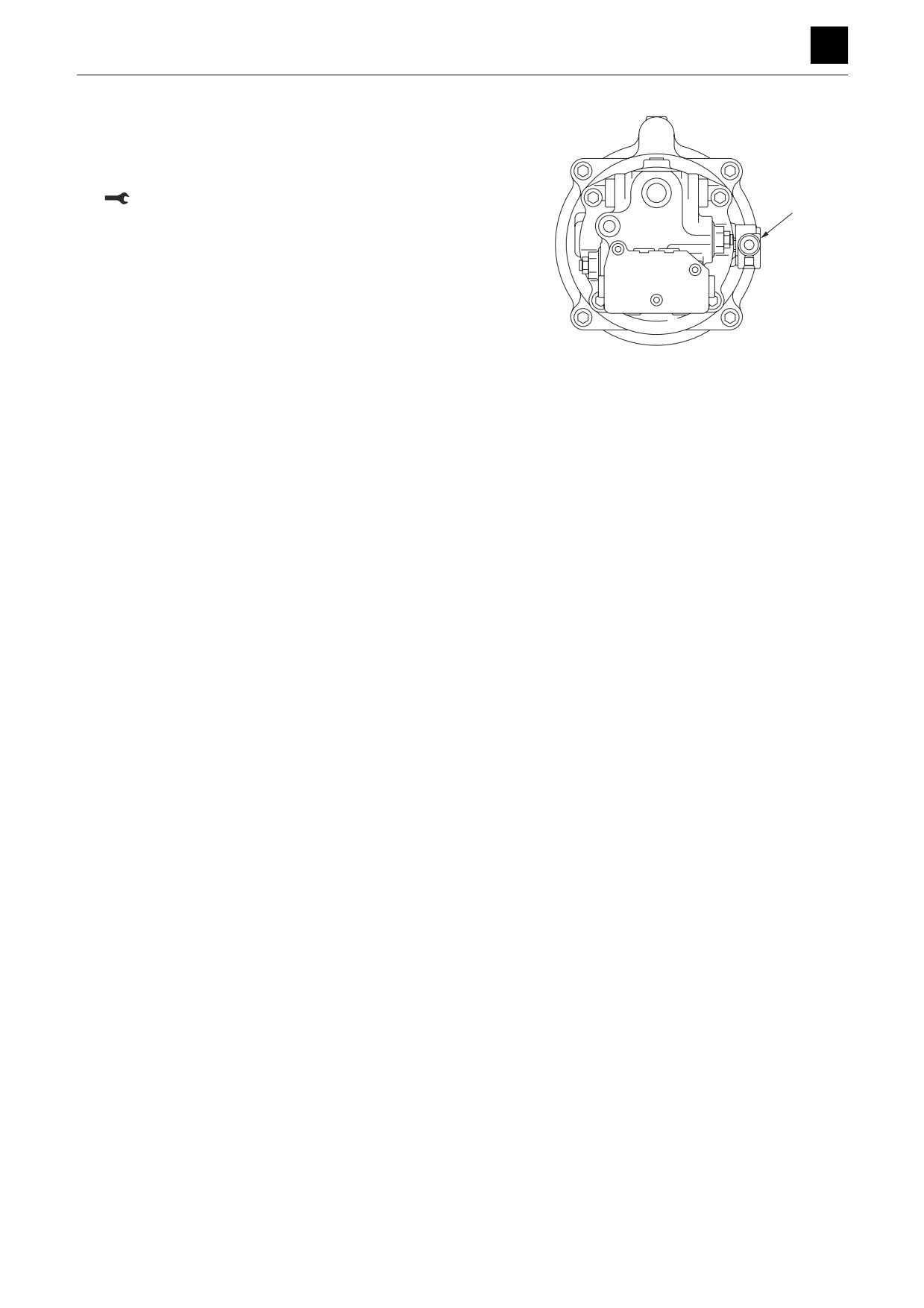
21. Insert the timer valve (1).
a. Insert the O-rings into the motor housing.
b. Affix the timer valve in place using the cap
screws.
9.2 N·m ± 1.0 N·m
22
SLEW MOTOR
4N0AS00
DISASSEMBLY AND ASSEMBLY
SLEW MOTOR 4
Reduction gears
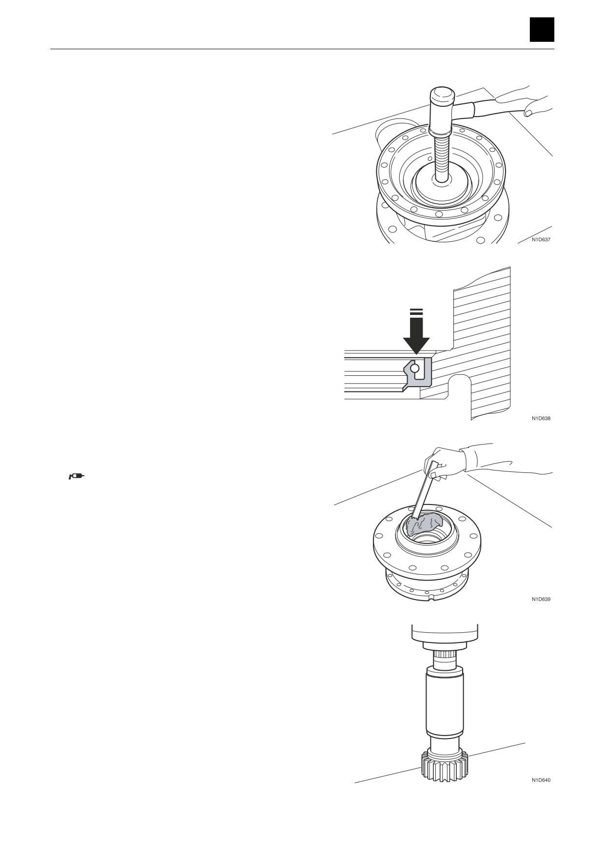
1. Attach the oil seal to the case.
• Grease the oil seal.
• Use the press-fitting jig (L).
2. Apply grease to the bearing attachment section in
the case.
SHELL RETINAX HD-2 or an equivalent
3. Attach the collar to the pinion shaft.
• Grease the inner circumference of the collar.
• Press-fit the collar onto the pinion shaft using the
press-fitting jig (G).
23
SLEW MOTOR
4N0AS00
DISASSEMBLY AND ASSEMBLY
SLEW MOTOR 4
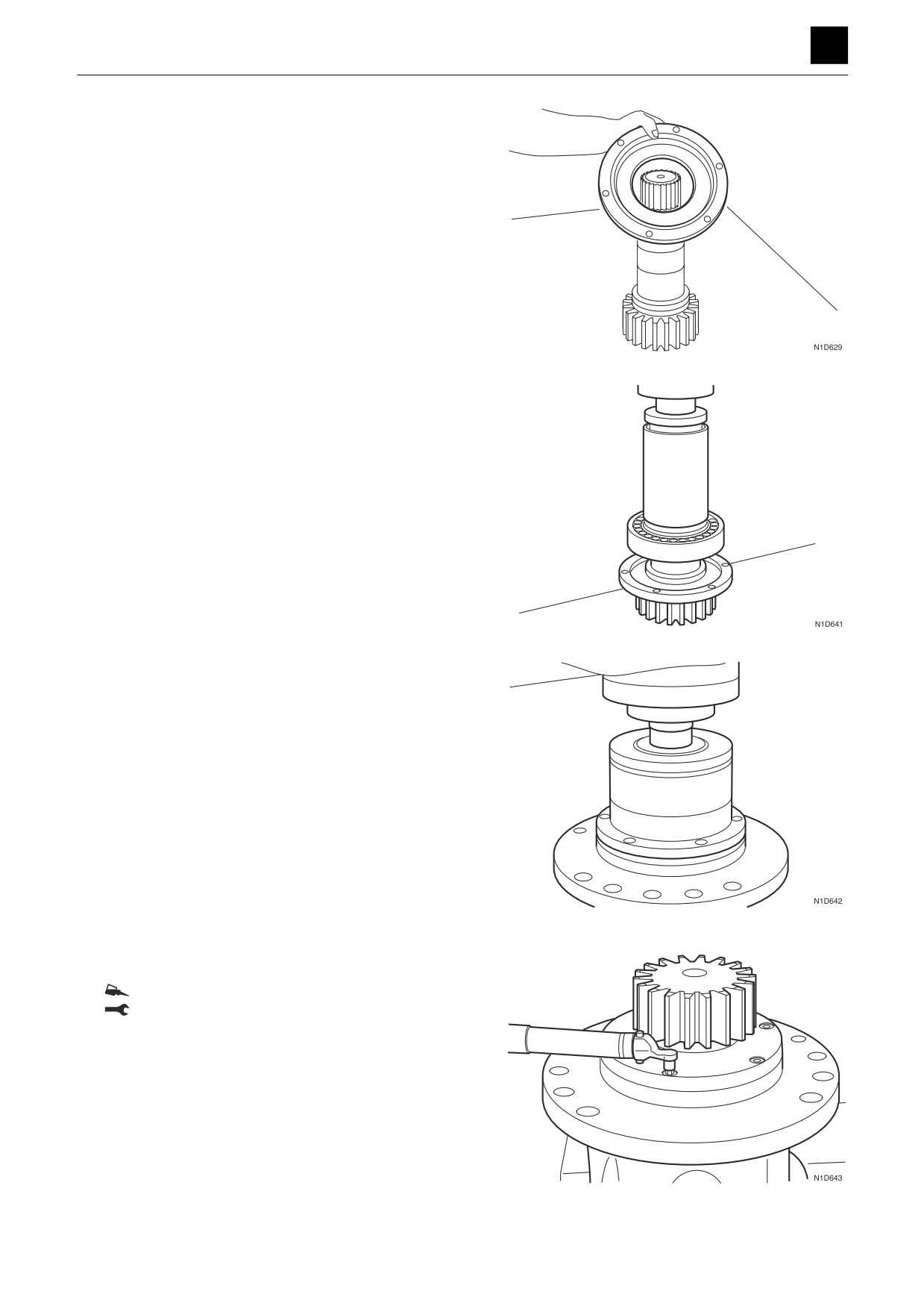
4. Attach the cover to the pinion shaft.
• Attach the seal ring to the cover.
5. Insert the bearing into the pinion shaft.
• Press-fit the bearing into the pinion shaft using the
press-fitting jig (G).
• Grease the bearing with SHELL RETINAX HD-2
grease or an equivalent.
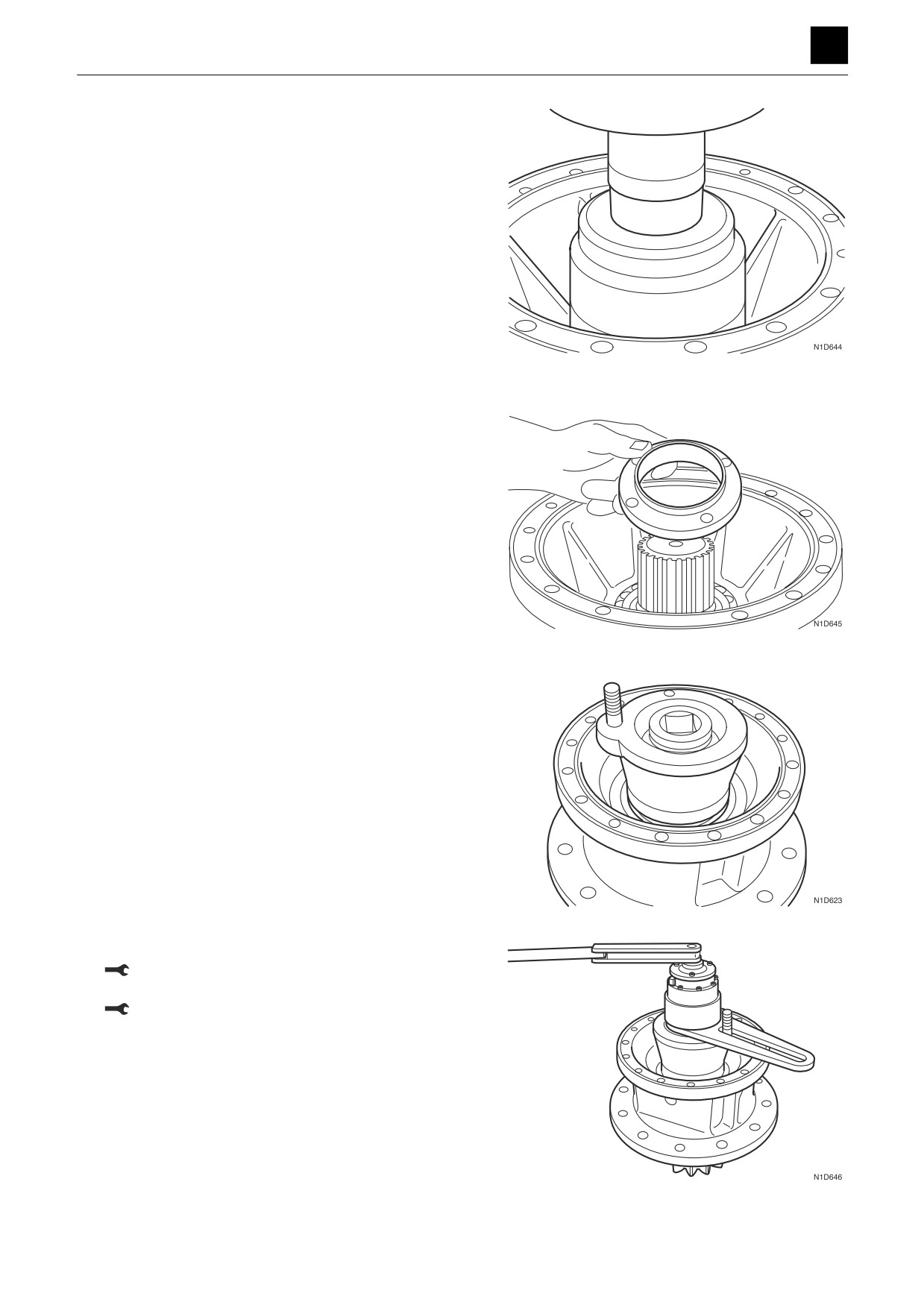
6. Insert the pinion shaft into the case.
• Press-fit the pinion shaft into the case using the
press-fitting jig (B).
7. Attach the cover, and affix it in place using the cap
screws.
Cap screw: Loctite #242
Cap screw: 24.5 N·m ± 4.9 N·m
24
SLEW MOTOR
4N0AS00
DISASSEMBLY AND ASSEMBLY
SLEW MOTOR 4
8. Insert the bearing into the pinion shaft.
• Grease the inner surfaces of the inner race on the
bearing.
• Press-fit the inner race into the pinion shaft using
the press-fitting jig (H).
9. Attach the ring nut to the pinion shaft.
10. Attach the stopper tool (I) and socket tool (J) to the
ring nut.
11. Use a torque multiplier wrench to tighten the ring nut.
Ring nut: 44 N·m to 48 N·m (Using a torque mul-
tiplier wrench)
Ring nut: 1100 N·m to 1200 N·m (Using a stan-
dard torque wrench)
25
SLEW MOTOR
4N0AS00
DISASSEMBLY AND ASSEMBLY
SLEW MOTOR 4
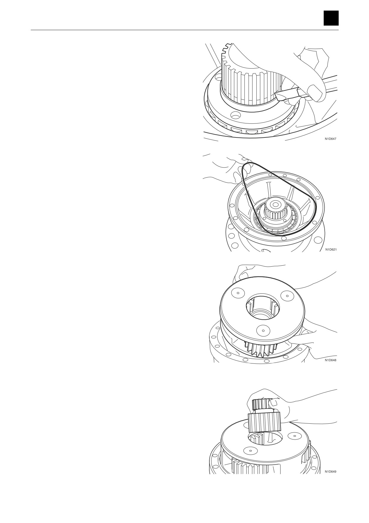
12. Swage the ring nut in three places (at intervals of
120°).
13. Insert the O-rings into the case.
• Grease the O-rings.
14. Insert the 2nd stage planet gear assembly.
15. Attach the sun gear.
26
SLEW MOTOR
4N0AS00
DISASSEMBLY AND ASSEMBLY
SLEW MOTOR 4
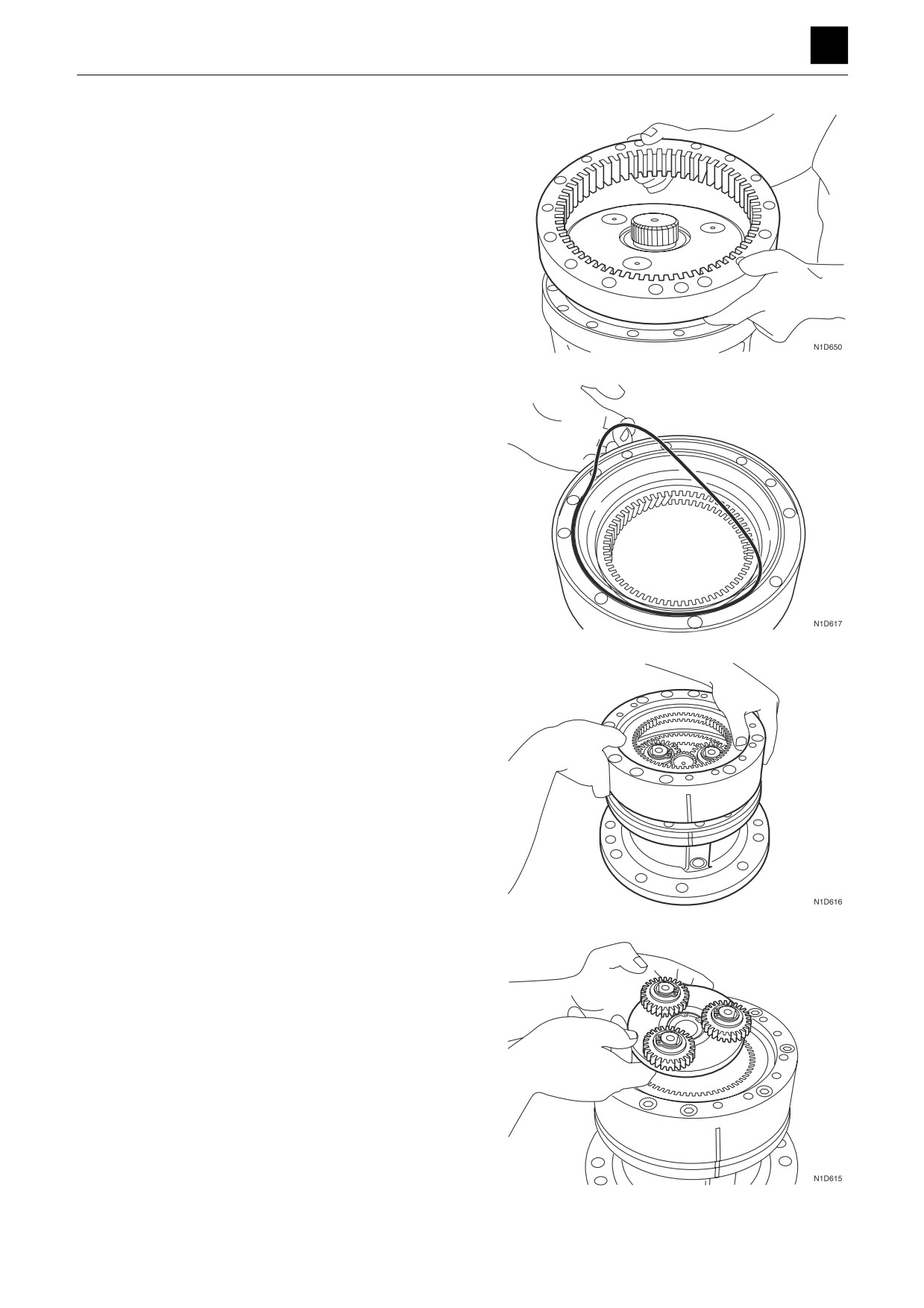
16. Attach the ring gear.
• Line up the assembly marks placed on the parts
before disassembly.
17. Attach the O-ring to the ring gear.
• Grease the O-ring.
18. Attach the ring gear.
• Line up the assembly marks placed on the parts
before disassembly.
19. Attach the 1st stage ring gear.
27
SLEW MOTOR
4N0AS00
DISASSEMBLY AND ASSEMBLY
SLEW MOTOR 4
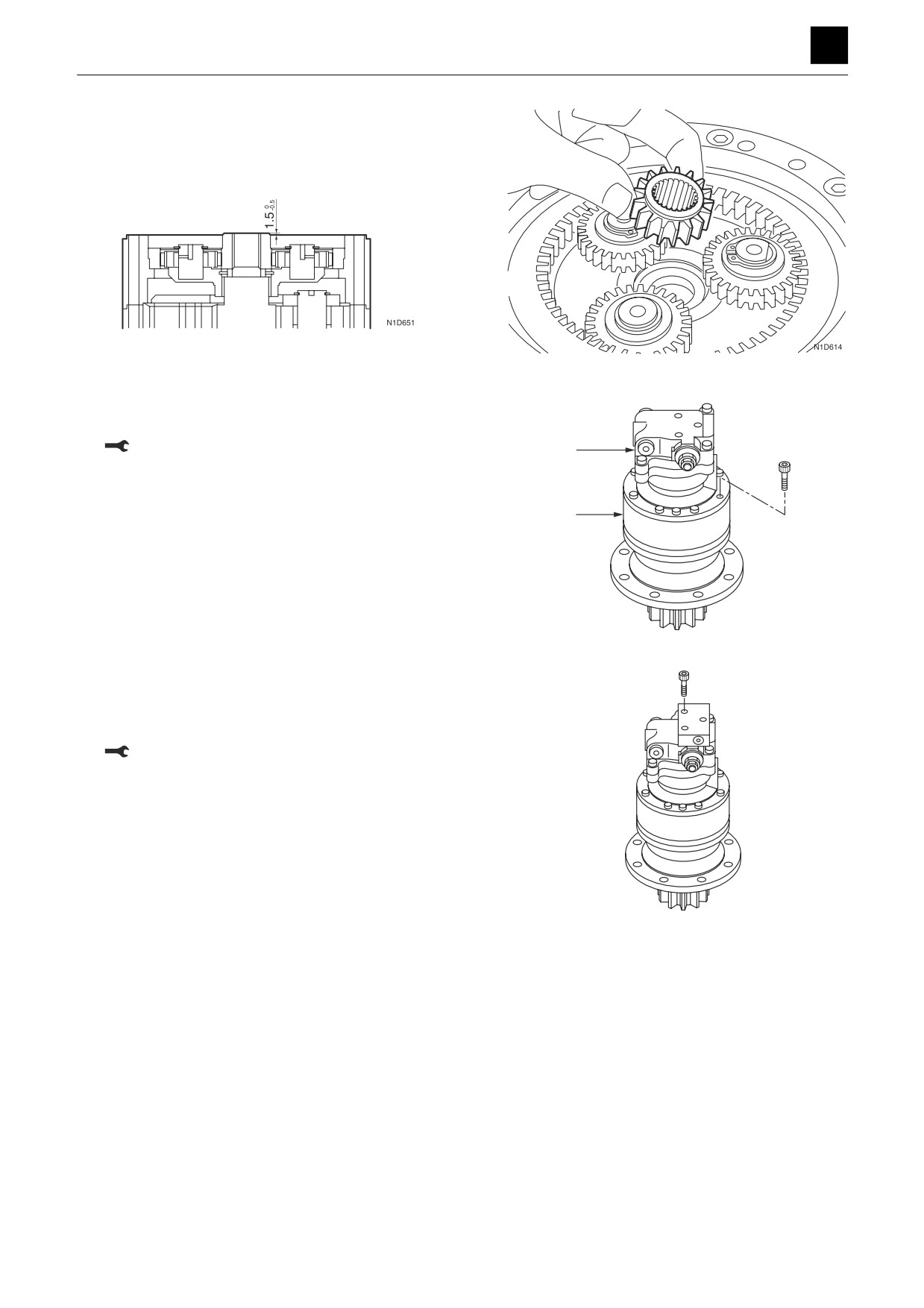
20. Attach the sun gear.
• Check to ensure that the part is at the below di-
mensions before attachment to the motor assem-
bly.
Slew motor
1. Attach the hydraulic motor (1) to the reduction gears
(2), and secure it in place using the cap screws.
Cap screw: 85 N·m ± 4.3 N·m
1
2
K3D627
2. Attach the O-ring to the valve body.
3. Insert the reversal prevention valve into the valve
body, and secure it in place using the cap screws.
Cap screw: 32.4 N·m ± 2.0 N·m
K3D626
28
SLEW MOTOR
4N0AS00
DISASSEMBLY AND ASSEMBLY
4
SLEW MOTOR
Inspection and adjustments
Use limit for parts
Brake valve
Part
Criteria
Action
Check valve,
• If there is severe damage to sliding parts or excessive surface rough-
•
Replace
piston
ness
• If there is a great amount of looseness occurring between the body
•
Replace
and the check valve, piston
• If there is severe damage to the seat or seating is not uniform
•
Replace
Housing
• If there is severe damage to sliding parts or excessive surface rough-
•
Replace
ness
• If there is damage, etc. that allows oil leakages to occur
•
Replace
Relief valve as-
• If there are abnormal drops in the set pressure
•
Replace
sembly
• If there is vibration due to the set pressure being unstable
•
Replace
• If there is increased leakage due to faulty seating
•
Replace
Spring
• If there is a high degree of breakage or deformation
•
Replace
Hydraulic motor
Standard
When replacement
Part
Action
dimension
recommended
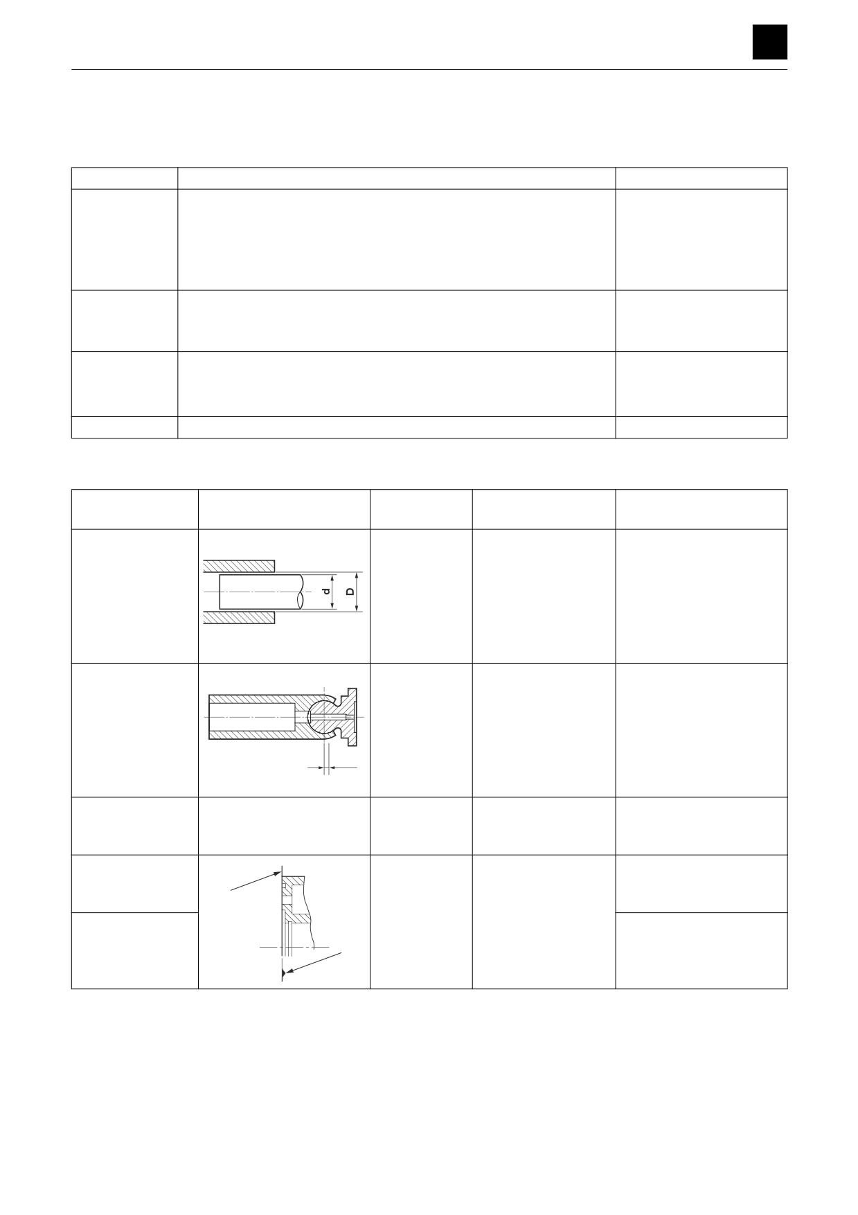
Clearance (S) be-
0.02 mm
0.04 mm (0.0016 in.)
Replace the cylinder block
tween the piston
(0.0008 in.)
and swash plate assembly
and cylinder bore
S = D-d
4I0AF22Z
Amount of loose-
0.15 mm
0.4 mm (0.016 in.)
Replace the cylinder block
ness (S) between
(0.006 in.)
and swash plate assembly
the piston and
shoe
S
4I0AF23Z
Bearings
If there is flaking or
Replace
pitching on the rolling
surface
Sliding surface (1)
If there is roughness
Repair with a lapping tool
of the cylinder
on the sliding surfac-
(Powder #1000) or replace
1
block
es
Sliding surface (2)
Replace
of the port block
2
4N0AF30Z
29
SLEW MOTOR
4N0AS00
DISASSEMBLY AND ASSEMBLY
4
SLEW MOTOR
Reduction gears
Part
Criteria
Action
Drive gear,
•
If there is pitting, abrasion, etc. occurring on the surface of the gear
•
Replace
housing, inter-
teeth
nal gear
•
If the amount of looseness between the housing, gears and the motor
•
Replace
joints has increased due to spline wear
Planetary gear
•
If there is pitting, abrasion, etc. occurring on the surface of the gear
•
Replace
teeth
•
If there is flaking, abrasion, etc. occurring on rolling surfaces of the
•
Replace
needle bearings
Needle bear-
•
If there is flaking, abrasion, etc. occurring on rolling surfaces of the
•
Replace
ing, planetary
needle bearings and shafts
shaft
•
If there are indentations, etc. occurring on rolling surfaces of the nee-
•
Replace
dle bearings and shafts
•
If there are abnormalities occurring in the rotation of the bearings
•
Replace
(abnormal noise generated, rotation not smooth, etc.)
Carrier, shaft
•
If there is a great amount of looseness occurring between the carri-
•
Replace
ers, shafts and the planetary shafts
Shaft
•
If the amount of looseness between the shaft and the pinion has in-
•
Replace
creased due to spline wear
Thrust washers
•
If there is an excessive amount of wear occurring
•
Replace
Ball bearing,
•
If there are abnormalities occurring in rotation (abnormal noise gen-
•
Replace
roller bearing
erated, rotation not smooth, etc.)
•
If there is flaking, abrasion, etc. occurring on rolling surfaces
•
Replace
•
If there are indentations, etc. occurring on rolling surfaces
•
Replace
Collar, oil seals,
•
If there is damage, etc. that allows oil leakages to occur
•
Replace
O-rings
Reversal prevention valve
Part
Criteria
Action
Check valve
• If there is severe damage to sliding parts or excessive surface rough-
•
Replace
ness
• If there is a great amount of looseness occurring between the body
•
Replace
and the check valve
• If there is severe damage to the seat or the seating is not uniform
•
Replace
Body
• If there is severe damage to sliding parts or excessive surface rough-
•
Replace
ness
• If there is damage, etc. that allows oil leakages to occur
•
Replace
Spring, sleeve
• If there is a high degree of breakage or deformation
•
Replace
30
SLEW MOTOR
4N0AS00
DISASSEMBLY AND ASSEMBLY
4
SWIVEL JOINT
SWIVEL JOINT
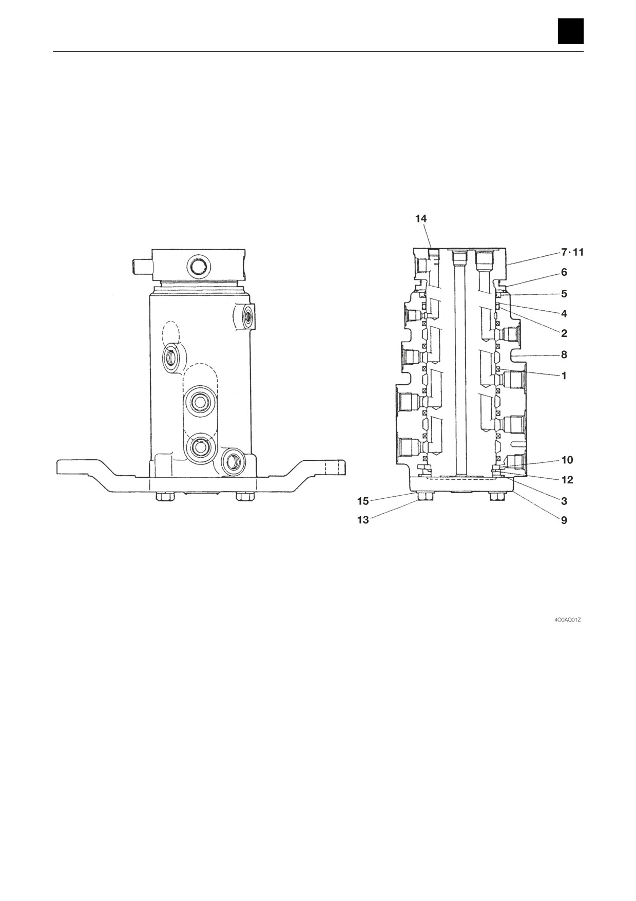
Construction
1. Seal
6. Dust seal
11. Pin
2. O-ring
7. Shaft
12. Snap ring
3. O-ring
8. Hub
13. Bolt
4. Backup ring
9. Flange
14. Plug
5. Dust seal
10. Spacer
15. Spring washer
1
SWIVEL JOINT
4O0AQ00
DISASSEMBLY AND ASSEMBLY
4
SWIVEL JOINT
Disassembly and Assembly
The numbers in parentheses () listed after the names of
parts in this document do not match the numbers used in
the construction diagrams and parts lists.
General Precautions
• Perform disassembly and assembly work in a clean
place. Provide clean containers to hold parts during
disassembly.
• Clean around the ports before disassembly. Remove
paint around connectors with a wire brush.
• Clean the disassembled parts with wash oil.
• Put alignment marks on all parts to reassemble them in
the same positions.
• After each disassembly, replace all seals and apply a
thin layer of grease to them.
• Check each part for abnormal wear or seizing. Re-
move any burrs with sandpaper.
Disassembly
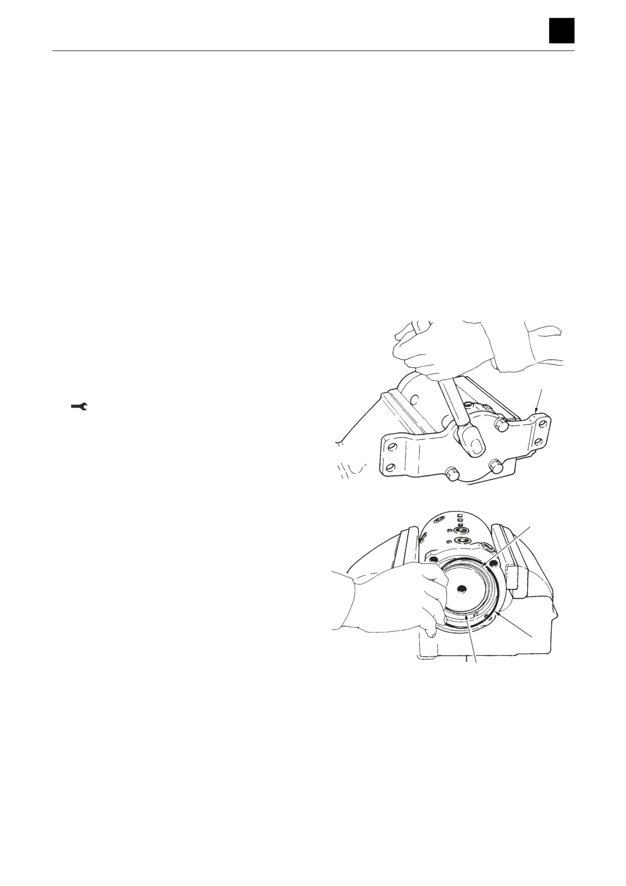
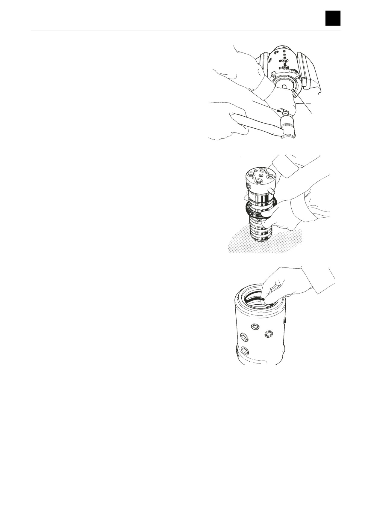
1. Take out the bolts and remove the hub from the
flange (1).
• Hold the hub in a vise.
• During assembly, use a pipe on the stopper pin of
1
the shaft to check that the shaft rotates smoothly.
Bolt: 24.5 to 39.2 N·m
4O0AF03Z
2. Remove the O-ring (2), snap ring (3) and thrust ring
4
(4).
• During assembly, ensure that the snap ring is
firmly engaged in the groove.
2
3
4O0AF04Z
2
SWIVEL JOINT
4O0AQ00
DISASSEMBLY AND ASSEMBLY
4
SWIVEL JOINT
3. Remove the shaft (5) from the hub.
• Place a knock pin (6) against the end of the shaft
and tap it with a hammer.
• Select a knock pin made of a material such as
copper or plastic.
• During assembly, apply a thin coating of hydrau-
lic oil to the outer circumference of the shaft.
6
5
4O0AF05Z
4. Remove the dust seals from the shaft.
4O0AF06Z
5. Remove the seals from the inside diameter of the
hub.
• Check the positions of the seals in the construc-
tion diagram.
• Remove the O-ring with an awl or similar pointed
tool.
• Do not strongly deform or bend localized portions
of the slipper seal.
• During assembly, make sure that the O-ring is not
twisted.
4O0AF07Z
Assembly
For assembly, refer to the construction diagram and re-
verse the disassembly procedure.
3
SWIVEL JOINT
4O0AQ00
DISASSEMBLY AND ASSEMBLY
4
SWIVEL JOINT
Inspection and adjustment
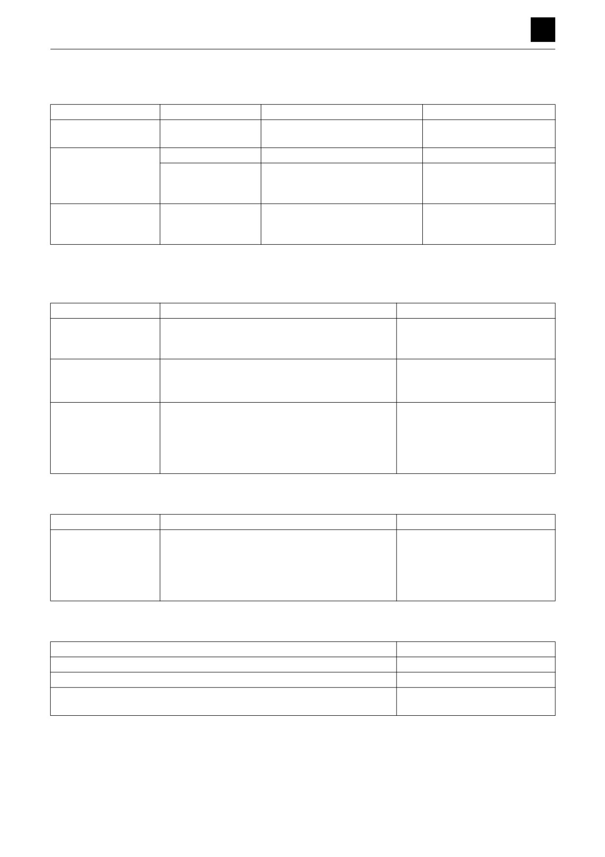
Inspection procedures and remedial actions
Inspection interval
Inspection point
Inspection procedure
Action
2000 hours
Seals preventing ex-
Check if oil is leaking externally.
If a leak is found, replace the
ternal leakage of oil
O-rings.
4000 hours
All seals
--
Replace all seal parts.
Disassemble and in-
All sliding surfaces
Check for abnormal wear, scratch-
Remedy in accordance with
spect regardless of
ing, or corrosion due to seizing or
the use limit of parts.
leaks
trapped foreign matter.
Disassembly due to
All parts
Check for abnormal wear, scratch-
Remedy in accordance with
malfunction
ing, or corrosion due to seizing or
the limit of use of parts.
trapped foreign matter.
Replace the seal kit.
Use limit for parts
Hub, shaft
Part
Criteria
Action
Areas in sliding contact
•
High-frequency induction-hardened surfaces worn
•
Replace
with seals
away; peeling due to seizing or trapping of foreign
matter
Sliding surfaces of hub
•
Abnormal wear or scratches 0.1 mm deep or more
•
Replace
and shaft (excepting
due to seizing or trapping of foreign matter
seals)
•
Scratches 0.1 mm deep or more
•
Repair with a grindstone
Sliding surfaces of
•
Wear exceeding 0.5 mm or abnormal wear
•
Replace
thrust ring
•
Wear not exceeding 0.5 mm
•
Repair to make surfaces smooth
•
Repairable scratches due to seizing or trapping of
•
Repair to make surfaces smooth
foreign matter that do not exceed the 0.5 mm wear
limit
Flange
Part
Criteria
Action
Areas in sliding contact
•
Wear exceeding 0.5 mm or abnormal wear
•
Replace
with shaft
•
Wear not exceeding 0.5 mm
•
Repair to make surfaces smooth
•
Repairable scratches due to seizing or trapping of
•
Repair to make surfaces smooth
foreign matter that do not exceed the 0.5 mm wear
limit
Thrust ring
Criteria
Action
Wear exceeding 0.5 mm or abnormal wear
Replace
Wear not exceeding 0.5 mm
Repair to make surfaces smooth
Repairable scratches due to seizing or trapping of foreign matter that do not ex-
Repair to make surfaces smooth
ceed the 0.5 mm wear limit
4
SWIVEL JOINT
4O0AQ00
DISASSEMBLY AND ASSEMBLY
4
SWIVEL JOINT
Inspection after assembly
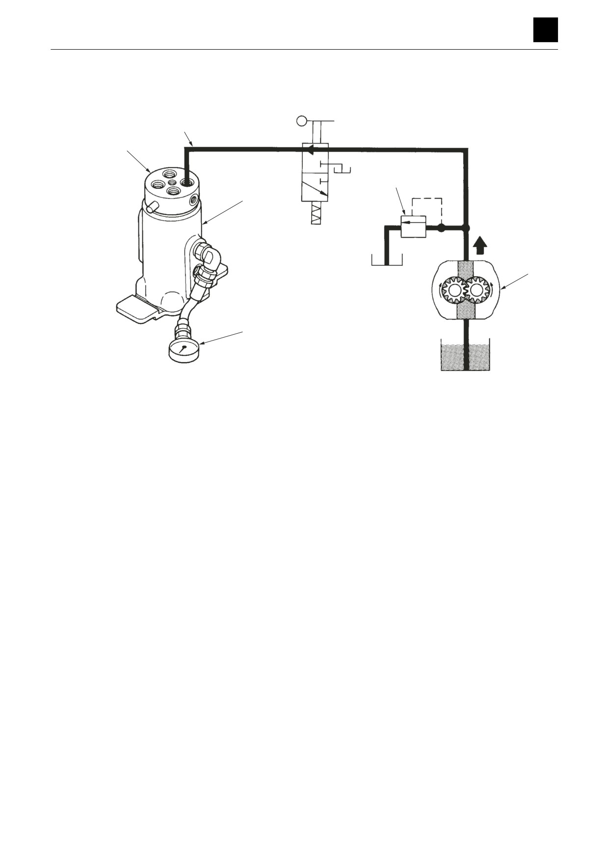
After assembly, perform an oil leak test on each circuit
using the apparatus shown in the figure.
3
1
6
4
2
5
4O0AF08Z
1. Connect the pipe (3) from the hydraulic pump (2) to
the shaft (1) side port.
2. Connect the pressure gauge (5) to the hub (4) side.
• Increase the pressure gradually to 20.6 MPa while
adjusting the relief valve (6). Perform the leak test
for one minute.
• Open the neighboring ports on both sides and vi-
sually check for leaks from the ports.
• Perform a color check to detect external leaks.
5
SWIVEL JOINT
4O0AQ00
5
TROUBLESHOOTING
Overall machine
Traveling
Slewing
Boom
Arm
Bucket
Boom swing
Blade
Auxiliary hydraulics
Piston pump
Gear pump
Control valve
Pilot valve
Solenoid valve
Cylinders
Travel motor
Slew motor
TROUBLESHOOTING
5
This “Troubleshooting” section describes the fault diagnosis and corrective actions mainly for hydraulic systems. The
cause of the problem can be investigated by following the steps in the chart shown at the beginning of each item.
Notes on troubleshooting and servicing
1. Do not disassemble the faulty part without first investigating the following.
a. Ask the user the following questions.
• The situation when the fault occurred.
• Any abnormalities or changes before the fault occurred.
• Any faulty parts other than the part in question.
• Any identical failure in the past
b. Drive the machine yourself and confirm the faulty condition.
• Determine if it is really faulty by referring to the performance criteria. Note that such determination may differ
depending on the person.
Important
By operating the user’s machine, you could make a bad situation worse. Therefore, before driving the machine, always
ask the user’s permission to do so.
c. Determine the cause of trouble based on the information obtained from the user and by driving the machine
yourself. Also remember that once the machine has been disassembled, it is almost impossible to reproduce
the conditions of the trouble, and so there will be no second chance to find out the true cause. Therefore be
sure to find the true cause of the trouble before attempting disassembly.
2. When multiple causes are suspected, start with the simplest one.
3. Think why the trouble occurred and try to correct the root cause of the problem.
1
5A0AQ00
TROUBLESHOOTING
5
OVERALL MACHINE
OVERALL MACHINE
No operation is possible.
Insufficient
Check the hydraulic oil
1
Add hydraulic oil.
level.
Sufficient
Faulty
• Repair or replace the hy-
Check the hydraulic
2
draulic pump.
pump.
• Replace the coupling.
1. Check the hydraulic oil level.
Check the hydraulic oil tank level.
“4. Disassembly and assembly, Hydraulic oil
tank”
When adding, use the same brand of oil currently be-
ing used.
“2. Service data, Fuel and lubricant table”
2. Check the hydraulic pump.
• Check the discharge pressure of the main hy-
draulic pump and sub hydraulic pump.
“2. Service data, Performance criteria.”
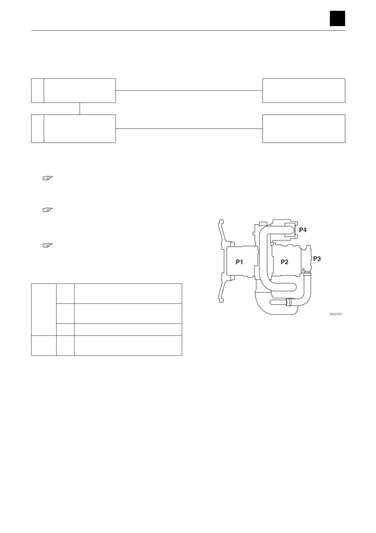
• Refer to the hydraulic pump assignment table for
details.
Right travel, slew, 1st auxiliary line pip-
P1
ing, boom [2], arm [1]
Main
Left travel, bucket, boom [1], arm [2],
P2
swing
P4
2nd auxiliary line, blade
Lever lock, 2nd speed travel, slew PB
Sub
P3
opened
1
OVERALL MACHINE
5B0AS00
TROUBLESHOOTING
5
OVERALL MACHINE
All systems working, but power insufficient.
Insufficient
Check the hydraulic oil
1
Add hydraulic oil.
level.
Sufficient
The hydraulic pump is
Noise
Replace the seal tape, O-ring
2
emitting an abnormal
Suction line faulty
and hose.
noise.
No noise
Action appropriate to the
Frothing in the tank
cause of the frothing.
Faulty
Check the main relief
3
Repair or replace.
valve.
Normal
The hydraulic pump is
4
Repair or replace.
faulty.
1. Check the hydraulic oil level.
Check the hydraulic oil tank level.
“4. Disassembly and assembly, Hydraulic oil
tank”
When adding, use the same brand of oil currently be-
ing used.
“2. Service data, Fuel and lubricant table”
2. The hydraulic pump is emitting an abnormal noise.
The noise is likely to be caused by cavitation in the
pump, due to a faulty suction line. Check the follow-
ing.
a. The lines for sucking the hydraulic oil.
• Apply grease or oil on the suspected faulty sec-
tions and check for a change. (check if air is
being sucked)
b. Clogging in the suction filter.
c. Apply pressure to the hydraulic oil tank.
“4. Disassembly and assembly, Hydraulic oil
tank”
3. Check the main relief valve.
Measure the relief pressure of the main relief valve.
• If the measured value is within the specifications,
the main relief valve is normal.
“2. Service data, Performance criteria”
2
OVERALL MACHINE
5B0AS00
TROUBLESHOOTING
5
OVERALL MACHINE
4. The hydraulic pump is faulty.
If the inside of the pump is excessively worn or dam-
aged, it is likely that metal pieces are in the hydraulic
oil. If this is the case, do the following.
• Replace the elements of the line filter and the re-
turn filter.
• Replace the hydraulic oil or perform flushing.
• When replacing the hydraulic oil, clean the tank
and the suction strainer.
If the pump seal is damaged, replace it.
3
OVERALL MACHINE
5B0AS00
TROUBLESHOOTING
5
OVERALL MACHINE
Boom, bucket, slew and arm fail to move or are too slow.
Faulty
• Repair or replace the gear
Check the hydraulic
1
pump.
pump.
• Replace the coupling.
Normal
Faulty
2
Check the fuse.
Replace the fuse.
Normal
Faulty
Adjust or replace the limit
3
Check the limit switch.
switch.
Normal
Faulty
Check the lever lock sole-
Repair or replace the lever
4
noid valve.
lock solenoid valve.
Normal
Faulty
Check the pilot relief
Repair or replace the pilot re-
5
valve.
lief valve.
Normal
Faulty
Repair or replace the pilot
6
Check the pilot valve.
valve.
1. Check the hydraulic pump.
Check the pump (P3) that supplies hydraulic pres-
sure for the pilot valve.
“2. Service data, Performance criteria”
Also, check the line filter for possible clogging, and
clean it if necessary.
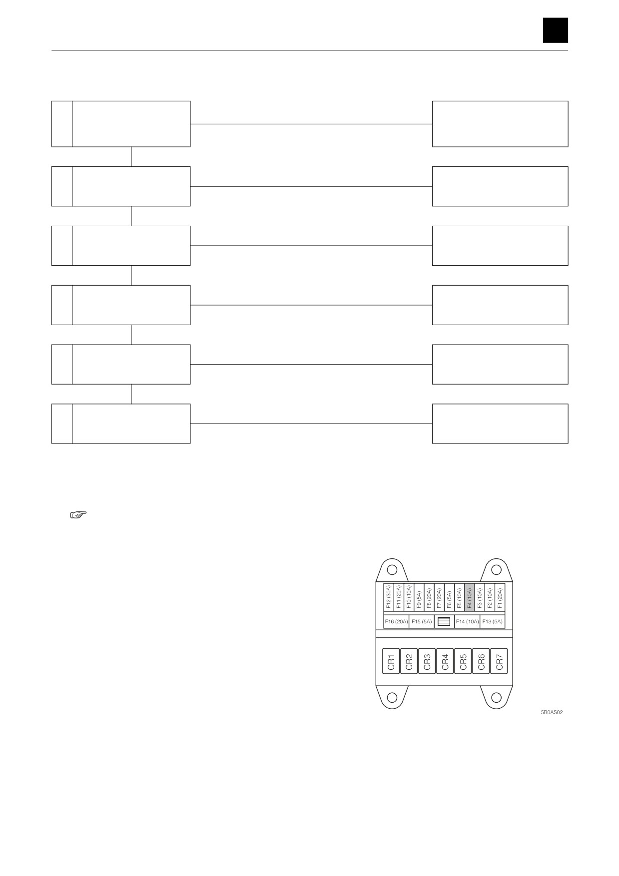
2. Check the fuse.
Check the fuse in the power supply circuit used to
run the solenoid valve.
4
OVERALL MACHINE
5B0AS00
TROUBLESHOOTING
5
OVERALL MACHINE
3. Check the limit switch.
The limit switch can be switched ON by moving the
lever stand to the driving position.
Then, use a tester to check if there is voltage up to
the lever lock solenoid valve.
• The switch is working normally if there is a voltage
present.
“2. Service data, Electrical circuit diagram”
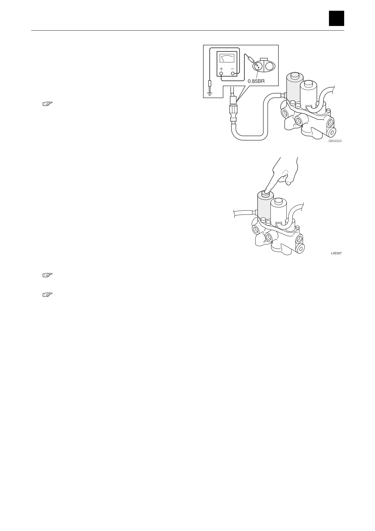
4. Check the lever lock solenoid valve.
Check according to the guidelines below.
a. Turn ON the starter switch.
b. Lightly press down the protruding part on the so-
lenoid end.
c. The limit switch changes from OFF to ON using
the lever stand.
d. If you feel vibration under your fingers when the
spool is moved and the circuit is switched, the le-
ver lock solenoid valve is normal.
5. Check the pilot relief valve.
Measure the relief pressure of the pilot relief valve.
• If the measured value is within the specifications,
the pilot relief valve is normal.
“2. Service data, Performance criteria”
6. Check the pilot valve.
“4. Disassembly and assembly, Pilot valve”
5
OVERALL MACHINE
5B0AS00
TROUBLESHOOTING
5
TRAVELING
TRAVELING
No right or left travel
Check the operation of
Abnormal
Check the main relief valve
1
actuators other than the
and pump.
travel motor.
Normal
Faulty
Check the pilot valve
Repair or replace the pilot
2
(travel).
valve (travel).
Normal
Faulty
Repair or replace the housing
3
Check the control valve.
block.
Normal
Faulty
Repair or replace the swivel
4
Check the swivel joint.
joint.
Normal
Faulty
Repair or replace the travel
5
Check the travel motor.
motor.
1. Check the operation of actuators other than the travel
motor.
• Check whether only the travel operation is faulty.
If the operation of other actuators is also defective,
see Overall machine.
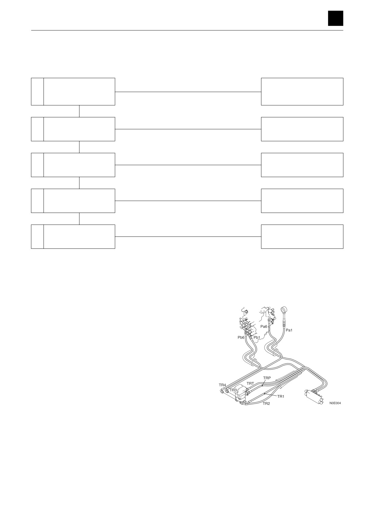
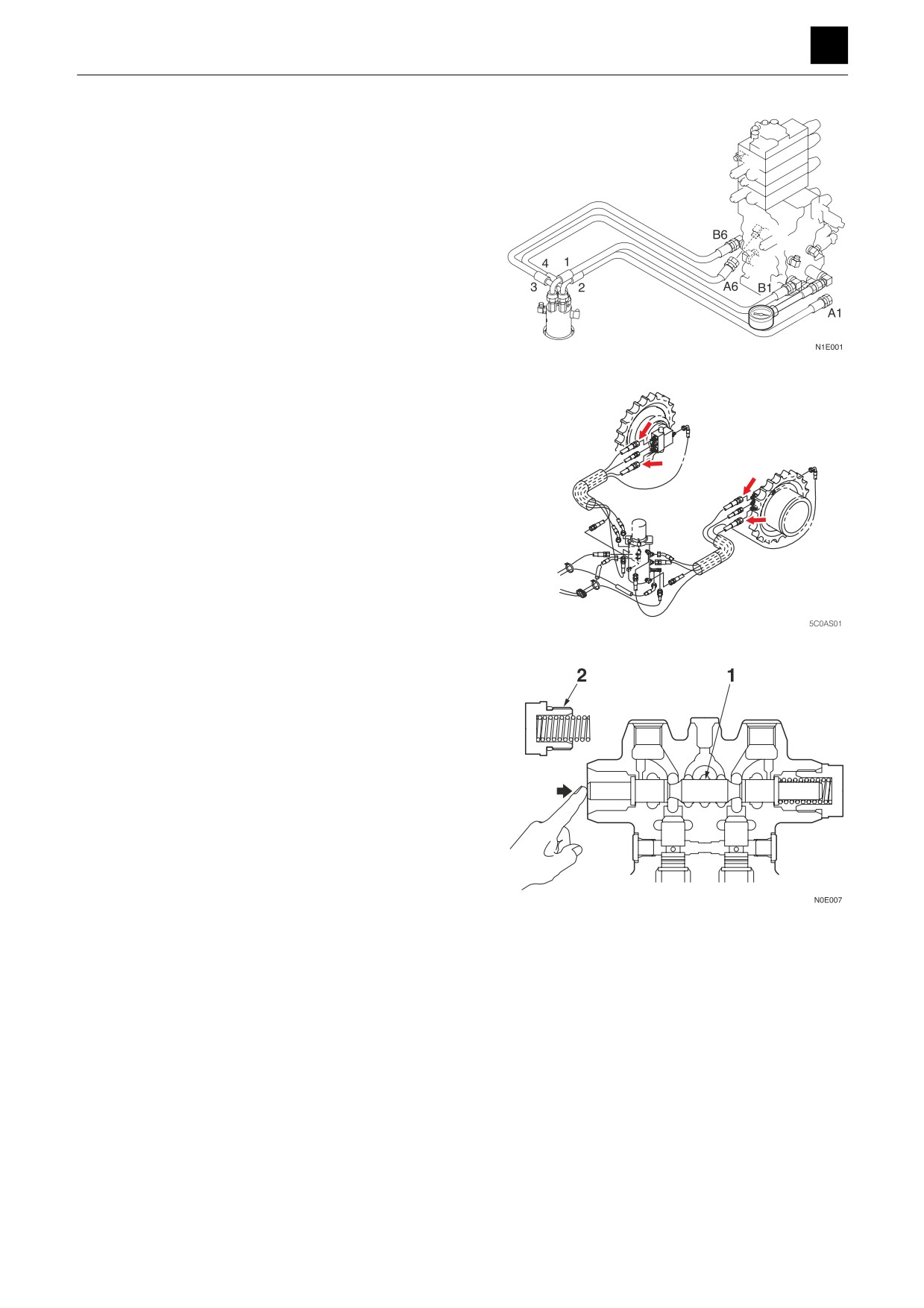
2. Check the pilot valve (Travel).
• Disconnect the hose connecting the pilot valve
and control valve (Pa1, Pb1, Pa6, Pb6) from the
control valve, and attach a pressure gauge to the
disconnected hose.
• Operate the travel lever, and measure the pres-
sure.
• The pilot valve is working normally if the pressure
varies between 0 MPa and 3.9 MPa (0 and 566
psi), according to the lever angle.
• If the measured pressure is found to be abnormal,
check the pilot valve.
1
TRAVELING
5C0AS00
TROUBLESHOOTING
5
TRAVELING
3. Check the control valve.
Disconnect the hose connecting the control valve
(A1, B1, A6, B6) and swivel joint from the control
valve, and attach a pressure gauge to the port of the
control valve.
• Operate the travel lever, and measure the pres-
sure.
Supply pressure: 34.3 MPa (4975 psi)
• If the measured pressure is found to be abnormal,
check the control valve.
4. Check the swivel joint.
Disconnect the hose connecting the swivel joint and
travel motor from the travel motor, and attach a pres-
sure gauge to the disconnected hose.
• Fit the pressure gauge to the section indicated by
the arrow.
• Operate the travel lever, and measure the pres-
sure.
• The valve is normal if the measured value stated
below is achieved.
Supply pressure: 34.3 MPa (4975 psi)
• If the measured pressure is found to be abnormal,
check the swivel joint.
5. Check the travel motor.
• If both forward travel and reverse travel are dis-
abled, the counterbalance valve spool (1) of the
travel motor may be stuck in the neutral position.
• If either forward or reverse travel is enabled but
the other is disabled, the counterbalance valve
spool (1) may be stuck in a position other than
neutral.
• Remove the plug (2) of the counterbalance valve,
and trying pushing on the spool (1) with a finger.
The spool (1) is working normally if it smoothly
moves by about 6 mm (0.24 in.).
For issues other than those listed above, check the
hydraulic motor and reduction gears of the travel mo-
tor.
2
TRAVELING
5C0AS00
TROUBLESHOOTING
5
TRAVELING
Right or left travel speed decelerates and the machine veers to one side.
Within spec
Is the veering value dur-
Problem caused by the
1
Normal
ing travel within spec?
combination of devices
Out-of-spec
Check the crawler belt
Faulty
Adjust to the specified crawl-
tension. Check for foreign
2
er tension and remove the for-
matter caught in the
eign matter.
crawler belt.
Normal
Faulty
Check the pilot valve
Repair or replace the pilot
3
(travel).
valve (travel).
Normal
Faulty
Repair or replace the housing
4
Check the control valve.
block.
Normal
Faulty
Repair or replace the swivel
5
Check the swivel joint.
joint.
Normal
Faulty
Repair or replace the travel
6
Check the travel motor.
motor.
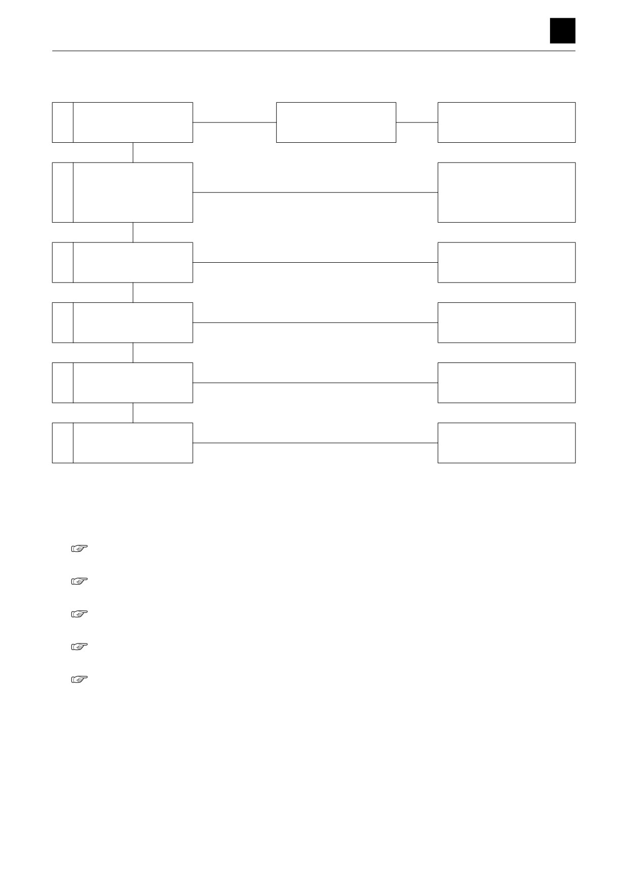
1. Is the veering value during travel within spec?
If the veering value falls within the specifications, the
machine is normal. The problem is caused by the
combination of devices.
“2. Service data, Performance criteria”
2. Adjust the crawler belt tension.
“2. Service data, Performance criteria”
3. Check the pilot valve (Travel).
“Traveling, No right or left travel”
4. Check the control valve.
“Traveling, No right or left travel”
5. Check the swivel joint.
“Traveling, No right or left travel”
3
TRAVELING
5C0AS00
TROUBLESHOOTING
5
TRAVELING
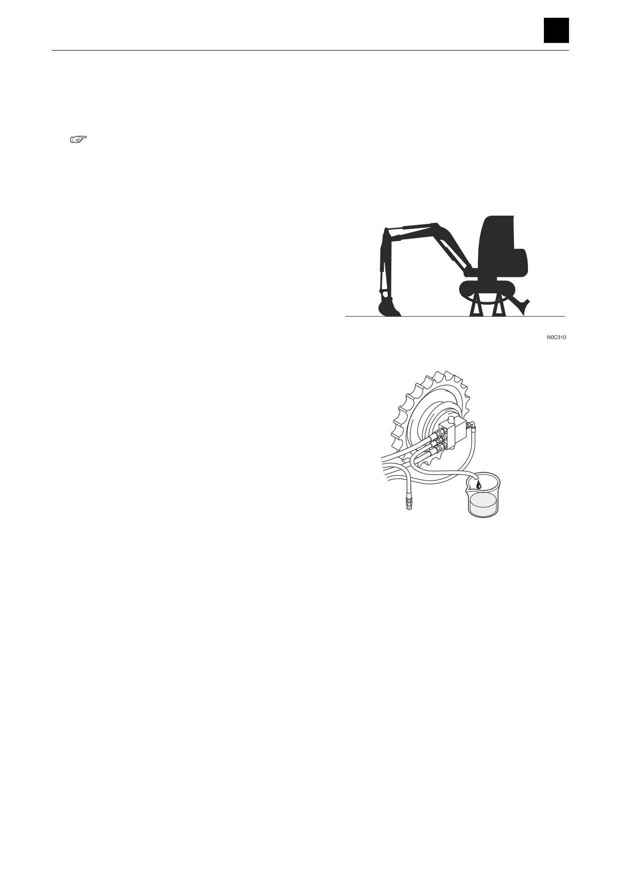
6. Check the travel motor.
<Checking the counterbalance valve>
Check the movement of the counterbalance valve
spool of the travel motor to ensure that it moves
smoothly.
“Traveling, No right or left travel, Check the trav-
el motor”
<Checking the drain volume from the travel motor>
Raise the machine using the hoe attachment and
blade, and then run the travel motor under the condi-
tions listed below to obtain a measurement of drain
volume over one minute.
a. Push the button on the air breather of the hydrau-
lic tank to release the internal pressure in the hy-
draulic tank.
b. Disconnect the drain hose connected to the travel
motor, and attach a plug to the disconnected
hose.
c. Attach a drain-measurement hose to the drain
port on the travel motor.
d. Run the travel motor at 1st-speed, and measure
the resultant drain volume.
• Hydraulic oil temp.: 50°C to 60°C (122°F to
140°F)
• Engine: Maximum RPM
• Drain volume: 1.2 L/min. (0.32 US gal./min.) or
less
For issues other than those listed above, check the
hydraulic motor of the travel motor.
5C0AS02
4
TRAVELING
5C0AS00
TROUBLESHOOTING
5
TRAVELING
2nd-speed travel is not possible.
Faulty
Check the hydraulic
1
Repair or replace the pump.
pump.
Normal
Faulty
Check the 2nd speed
2
Repair or replace.
travel switch.
Normal
Faulty
Check the 2nd-speed so-
Repair or replace the 2nd-
3
lenoid valve.
speed solenoid valve.
Normal
Faulty
Repair or replace the swivel
4
Check the swivel joint.
joint.
Normal
Faulty
5
The travel motor is faulty
Repair or replace.
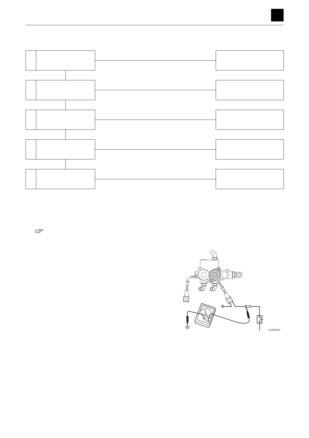
1. Checking the hydraulic pump.
Check the pump P3 that supplies hydraulic pressure
for the pilot valve.
“2. Service data, Performance criteria”
Also, check the line filter for possible clogging, and
clean it if necessary.
2. Check the 2nd speed travel switch.
a. Press the switch to turn it on. Use a tester to check
if there is a voltage present.
The switch is working normally if there is a voltage
present.
b. Check the harness continuity.
c. Check the switch.
d. Check the controller.
5
TRAVELING
5C0AS00
TROUBLESHOOTING
5
TRAVELING
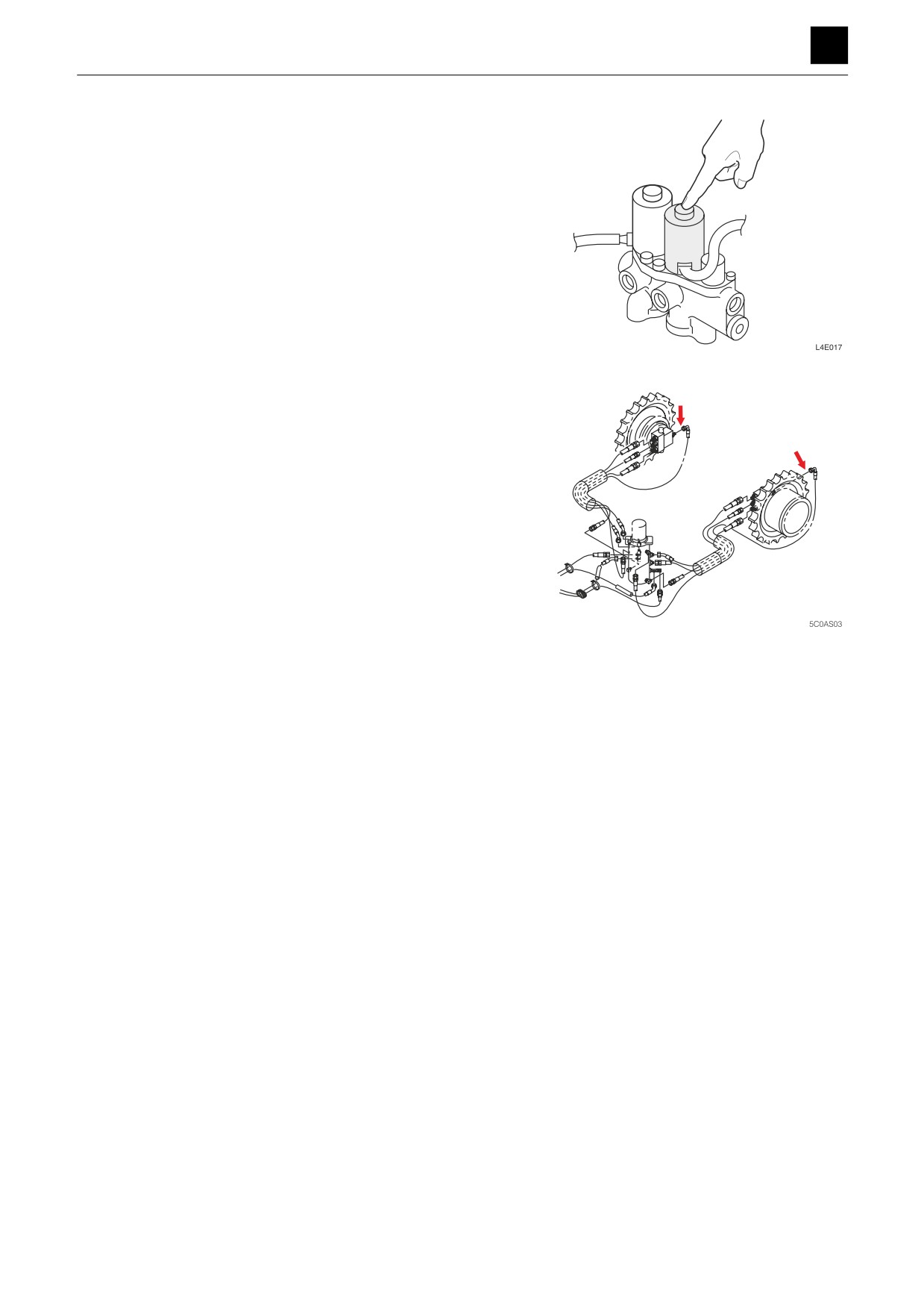
3. Check the 2nd-speed solenoid valve.
Check according to the guidelines below.
a. Turn ON the starter switch.
b. Lightly press down the protruding part on the so-
lenoid end.
c. The 2nd-speed travel switch changes from OFF to
ON.
d. If you feel vibration under your fingers when the
spool is moved and the circuit is switched, the
2nd-speed solenoid valve is normal.
• If the switching is abnormal, check the solenoid
valve.
4. Check the swivel joint.
Disconnect the travel motor end of the hose connect-
ing the swivel joint and travel motor. Attach a pres-
sure gauge to the disconnected hose. Turn on the
2nd-speed switch.
• Fit the pressure gauge to the section indicated by
the arrow.
• Supply pressure: 3.9 MPa (566 psi)
5. The travel motor is faulty.
Repair or replacve the 2nd speed control valve of the
travel motor.
6
TRAVELING
5C0AS00
TROUBLESHOOTING
5
SLEWING
SLEWING
No slew movement.
Faulty
Repair or replace the pilot
1
Check the pilot valve.
valve.
Normal
Faulty
Repair or replace the housing
2
Check the control valve.
block.
Normal
Pressure too low
Adjust the slew relief
3
Check the slew pressure.
Adjust to the set pressure.
valve pressure.
Normal
Pressure does not in-
crease
Repair or replace the slew re-
lief valve.
Faulty
Repair or replace the slew
4
Check the slew motor.
motor.
Normal
Slew bearing is faulty.
Replace
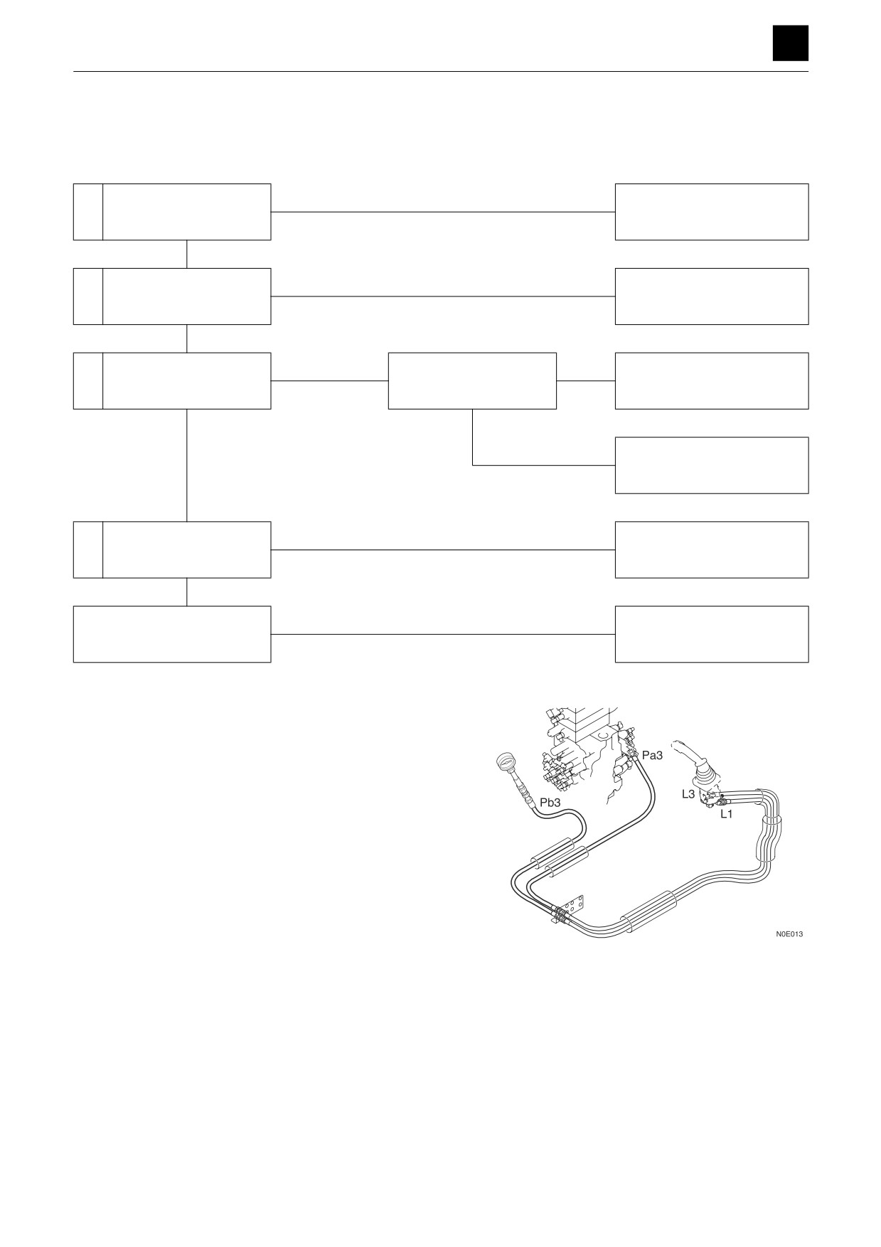
1. Check the pilot valve.
Disconnect the hose between the pilot valve and
control valve (Pa3, Pb3) from the control valve, and
attach a pressure gauge to the disconnected hose.
• Operate the lever (slew), and measure the pres-
sure.
• The pilot valve is working normally if the pressure
varies between 0 MPa and 3.9 MPa (0 and 566
psi), according to the lever angle.
1
SLEWING
5D0AS00
TROUBLESHOOTING
5
SLEWING
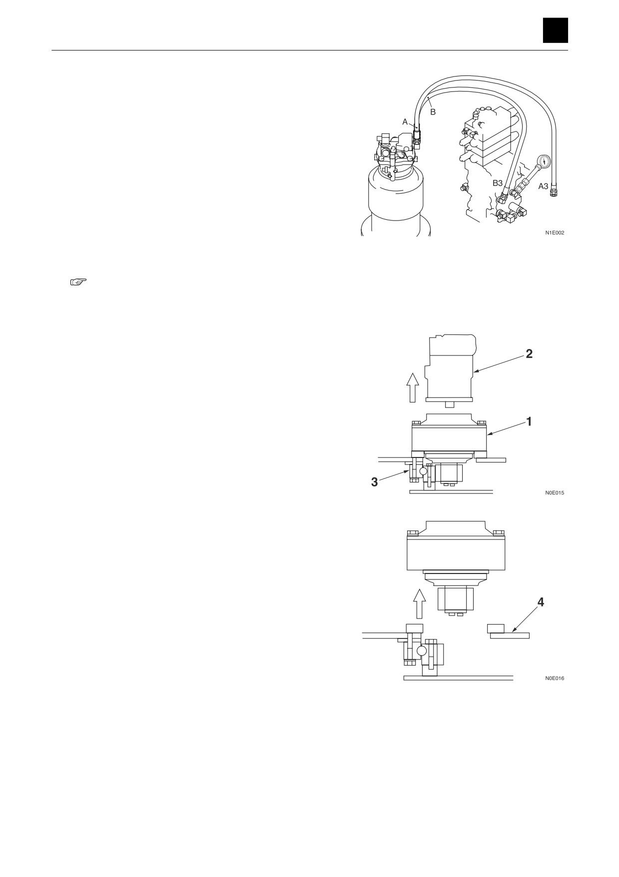
2. Check the control valve.
Disconnect the hose connecting the control valve
(B3, A3) and slew motor from the control valve, and
attach a pressure gauge to the port of the control
valve.
• Operate the lever (slew), and measure the pres-
sure.
• The valve is normal if the measured value stated
below is achieved.
Supply pressure: 33.3 MPa (4830 psi)
3. Check the slew pressure.
Measure the pressure at the right and left slew relief
valves.
• If the measured value is within the specifications,
the slew pressure is normal.
“2. Service data, Performance criteria”
If the pressure can be adjusted, the slew relief valve
adjustment is incorrect. If the pressure cannot be ad-
justed, the slew relief valve is faulty.
4. Check the slew motor.
<Motor>
Separate the reduction gear (1) from the motor (2),
and try to rotate the motor (2).
• If it rotates
The reduction gear (1) or slew
bearing (3) is faulty.
• If it fails to rotate
The slew motor (2) is faulty.
<Reduction gear>
Separate the reduction gear from the turntable (4),
and try to rotate the pinion by hand.
• If it rotates
The slew bearing (3) is faulty.
• If it fails to rotate
The reduction gear is faulty.
2
SLEWING
5D0AS00
TROUBLESHOOTING
5
SLEWING
No right or left slew movement.
Faulty
Repair or replace the pilot
1
Check the pilot valve.
valve.
Normal
Faulty
Repair or replace the housing
2
Check the control valve.
block.
Normal
Faulty
Check the slew relief
Repair or replace the slew re-
3
valve.
lief valve.
Normal
Faulty
Check the check valve in
Repair or replace the brake
4
the slew brake valve.
valve.
Normal
Repair or replace the slew
5
Slew motor is faulty.
motor.
1. Check the pilot valve.
The pilot valve spool may be faulty only on the side
where slew movement fails to occur.
“No slew movement, Check the pilot valve.”
2. Check the control valve.
Spool may fail to move only on the side where slew
movement fails to occur.
“No slew movement, Check the control valve.”
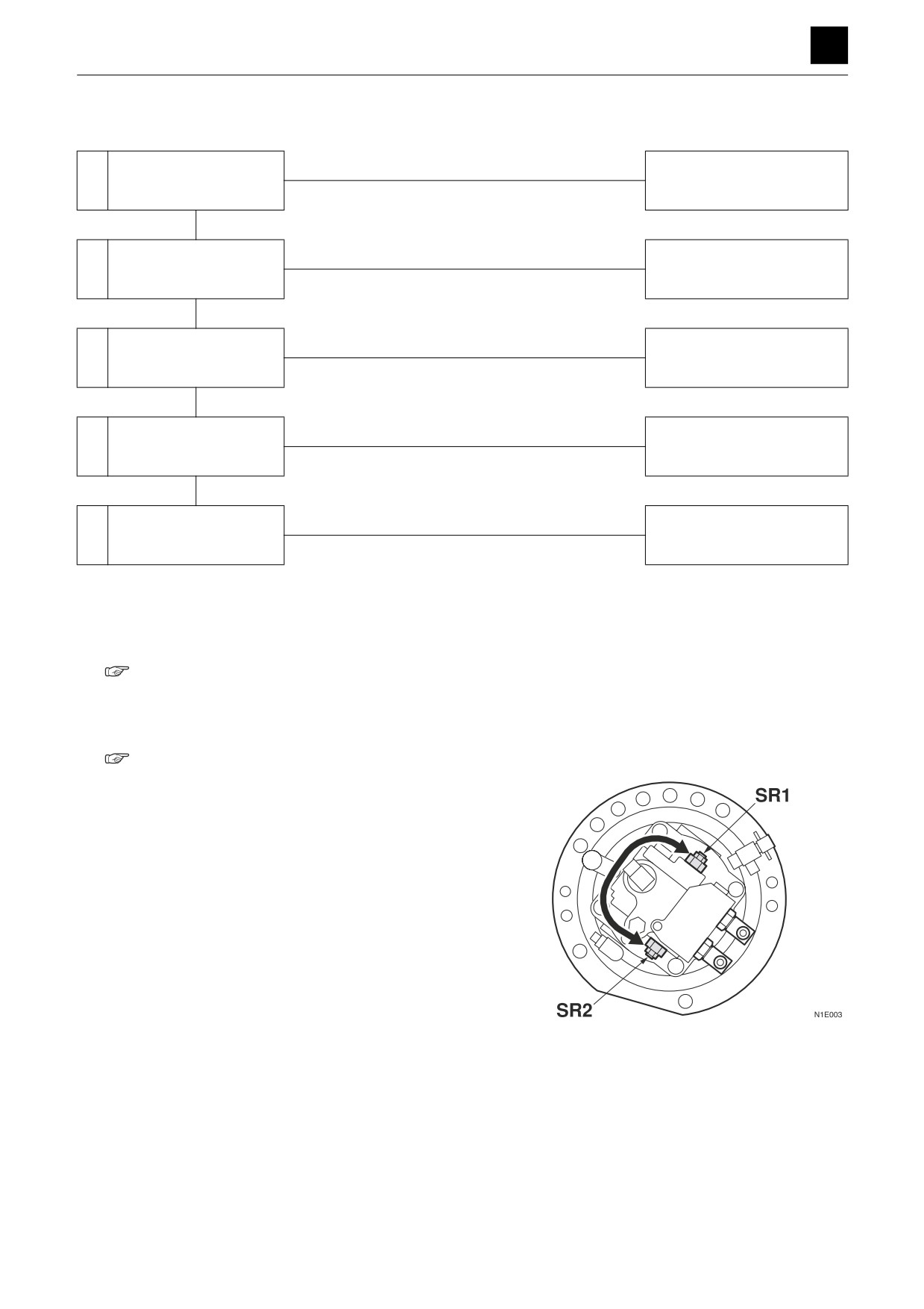
3. Check the slew relief valve.
Switch the left and right slew relief valves. If slewing
becomes possible, the relief valve is faulty.
3
SLEWING
5D0AS00