Takeuchi Hydraulic excavator TB1140 (Serial No. 514400002~). Operator's Manual - page 8
DISASSEMBLY AND ASSEMBLY
4
SHOCKLESS VALVE
Disassembly and assembly
The numbers in parentheses, ( ), listed after the names of
parts throughout this document do not necessarily match
the numbers of the same parts listed in the construction
diagrams and parts lists. The numbers listed are for part
numbers used in illustrations.
General precautions
•
Perform disassembly and assembly work in a clean
place. Provide clean containers to hold parts during
disassembly.
•
Clean around the ports before disassembly. Remove
paint around connectors with a wire brush.
•
Clean the disassembled parts with wash oil.
•
Put alignment marks on all parts to ensure that they are
reassembled in the same positions.
•
After each disassembly, replace all seals and apply a
thin layer of grease to each.
•
Check each part for abnormal wear or seizing. Re-
move any burrs with sandpaper.
•
Remove adhesive from screw holes that use adhesive
through the tap. Do not reuse mounting bolts or
screws.
•
Do not use cloth gloves during assembly. Fibers from
the gloves could fall off and clog valves, etc., which
could cause parts to become faulty.
•
During assembly, be sure to apply clean hydraulic oil
to all moving parts in and sliding parts that come into
contact with the hydraulic motor and valve parts be-
fore installing or attaching the part.
•
Plug all ports once assembly has been completed in
order to prevent dust and dirt from entering.
•
Do not attempt to adjust the adjusting screws at times
other than when necessary.
Disassembly
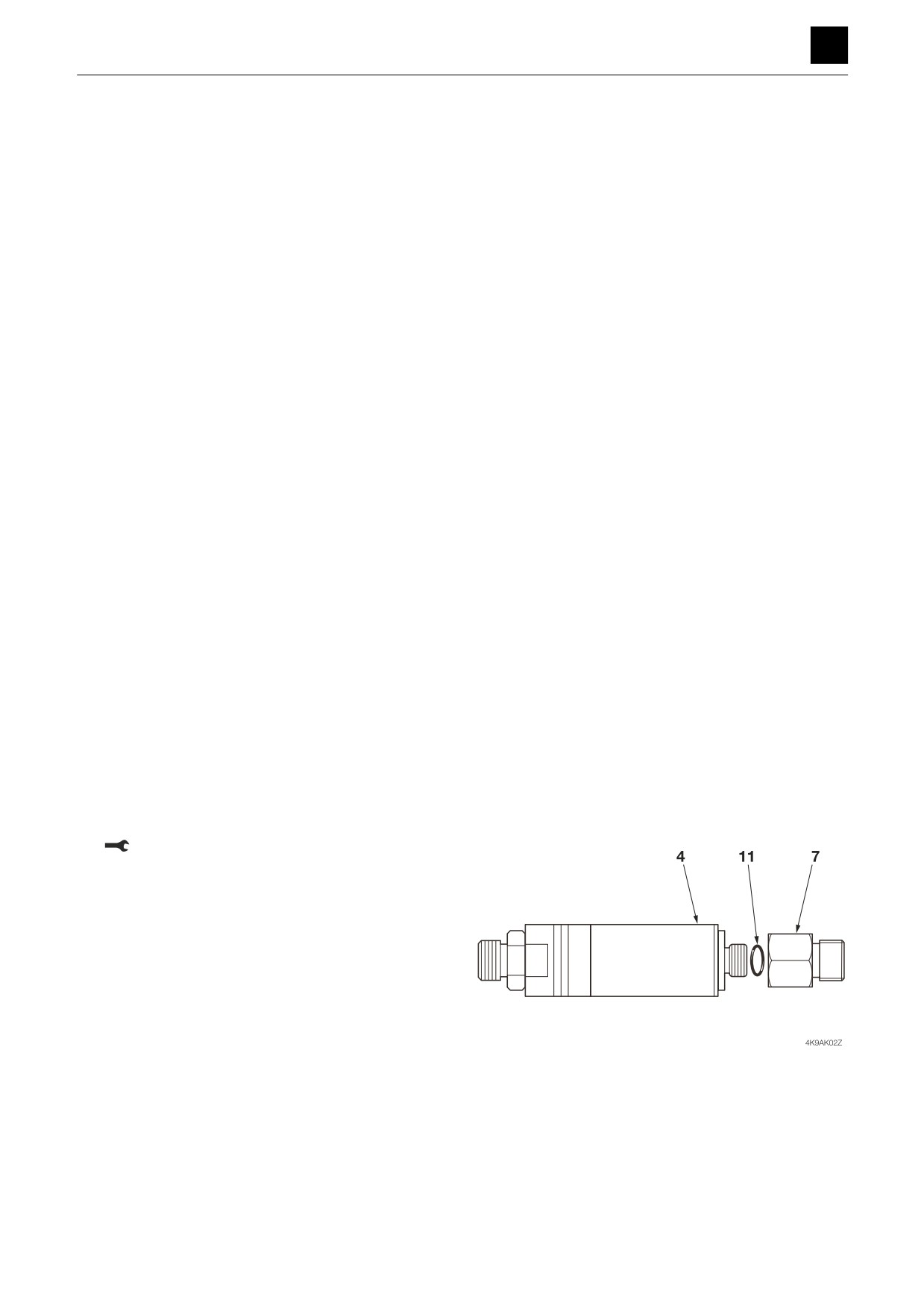
1. Remove the connector (7) from the body (4), and re-
move the O-ring (11).
Connector: 34.3 N·m ± 4.9 N·m
2
SHOCKLESS VALVE
4K9AS00
DISASSEMBLY AND ASSEMBLY
4
SHOCKLESS VALVE
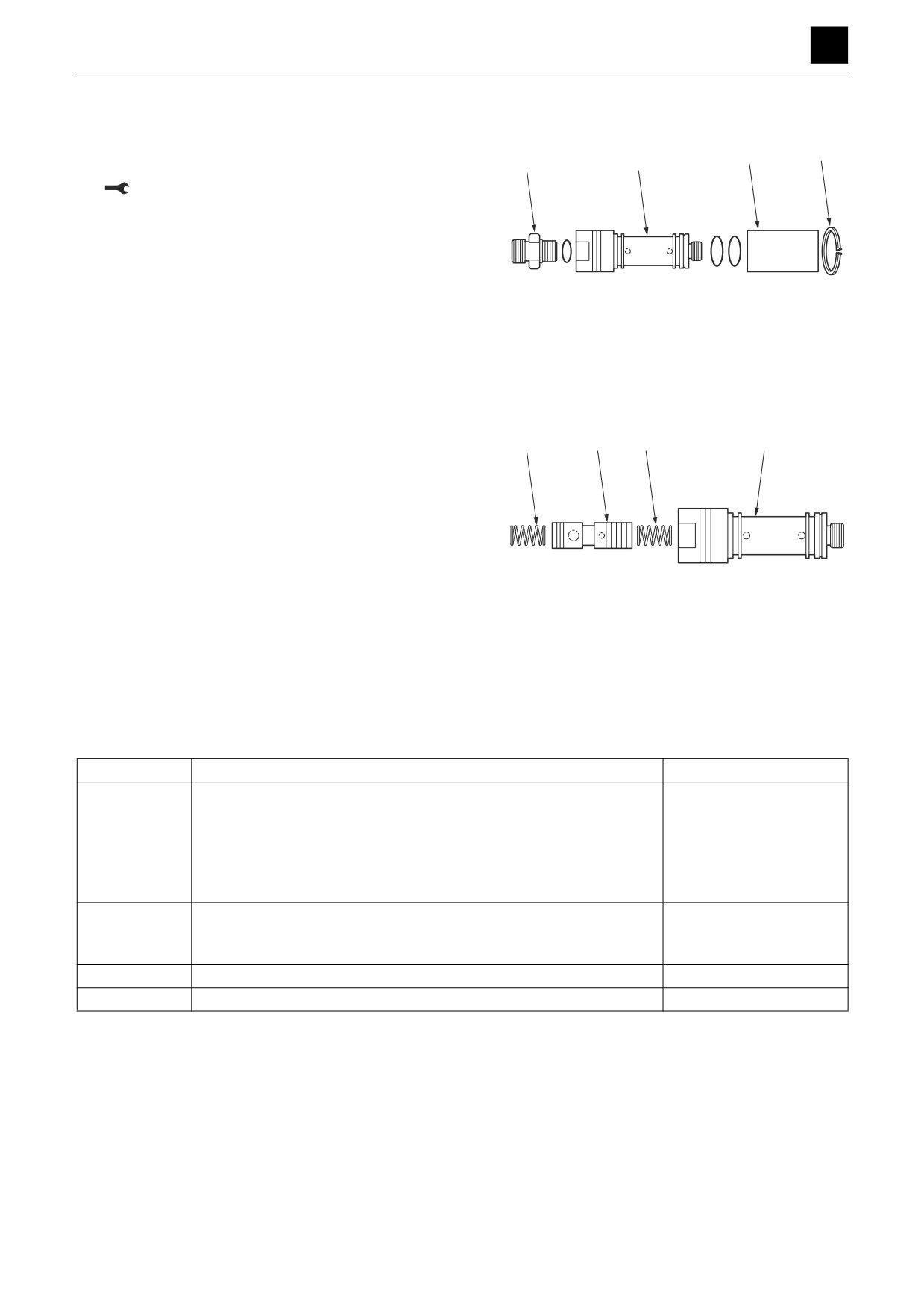
2. Remove the snap ring (9), and remove the sleeve.
3. Take out the connector (6), and remove the O-ring
5
9
6
4
(12).
Connector: 48.5 N·m ± 4.9 N·m
4K9AK03Z
4. Remove the spring (3) and plunger (1) from the body
(4).
3
1
3
4
Assembly
For assembly, refer to the construction diagram and re-
verse the disassembly procedure.
4K9AK04Z
Inspection and adjustments
Inspection
Part
Criteria
Action
Body
• If there are scratches, rust, or corrosion present on the parts that
• Replace
make sliding contact with the spool
• If there are scratches, rust, or corrosion on the seal part in contact
• Replace
with the O-ring
• If there is other damage present that could possibly impair normal
• Replace
operation of the machine
Plunger
• If there are scratches on the outer circumference that could easily
• Replace
get caught on by a fingernail
• If the spool does not move smoothly enough
• Repair or replace
Spring
• If there is rust, corrosion, deformation, or breakage present
• Replace
O-rings
—
• Replace
3
SHOCKLESS VALVE
4K9AS00
DISASSEMBLY AND ASSEMBLY
4
CYLINDERS
CYLINDERS
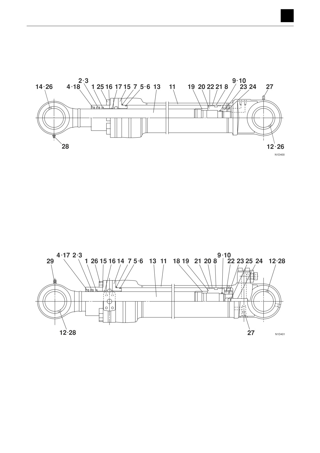
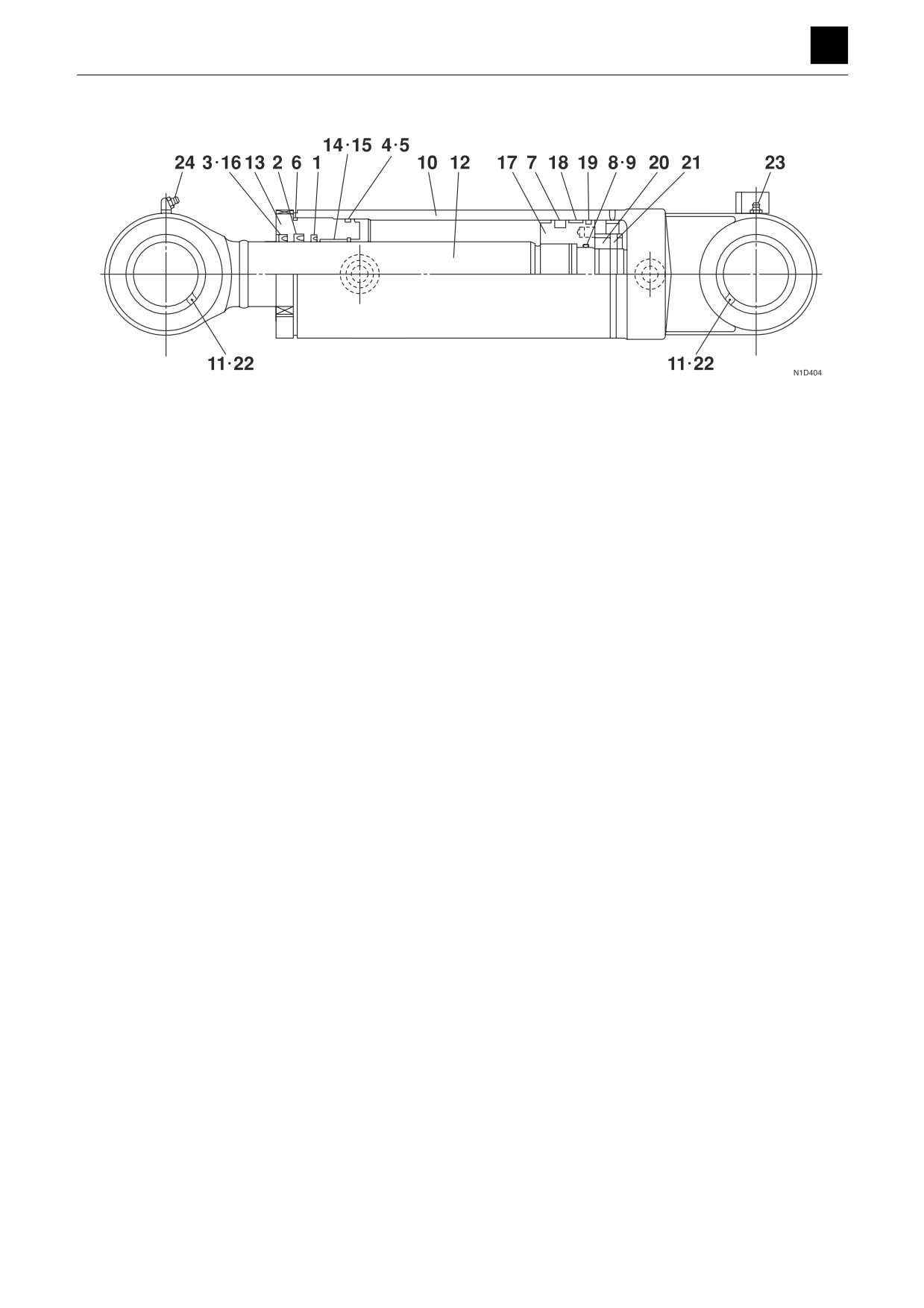
Construction
Boom cylinder
1. Buffer ring
8. Piston packing
15. Rod cover
22. Dust ring
2. Rod packing
9. O-ring
16. Bushing
23. Nut
3. Backup ring
10. Backup ring
17. Snap ring
24. Set screw
4. Dust seal
11. Tube
18. Snap ring
25. Cap screw
5. O-ring
12. Bushing
19. Cushion bearing
26. Dust seal
6. Backup ring
13. Piston rod
20. Piston
27. Grease nipple
7. O-ring
14. Bushing
21. Wear ring
28. Grease nipple
Arm cylinder
1. Buffer ring
9. O-ring
17. Snap ring
25. Stop ring
2. Rod packing
10. Backup ring
18. Cushion bearing
26. Cap screw
3. Backup ring
11. Tube
19. Piston
27. Check valve
4. Dust seal
12. Bushing
20. Wear ring
28. Dust seal
5. O-ring
13. Piston rod
21. Dust ring
29. Grease nipple
6. Backup ring
14. Rod cover
22. Nut
7. O-ring
15. Bushing
23. Set screw
8. Piston packing
16. Snap ring
24. Plunger
1
CYLINDERS
4L0AS00
DISASSEMBLY AND ASSEMBLY
4
CYLINDERS
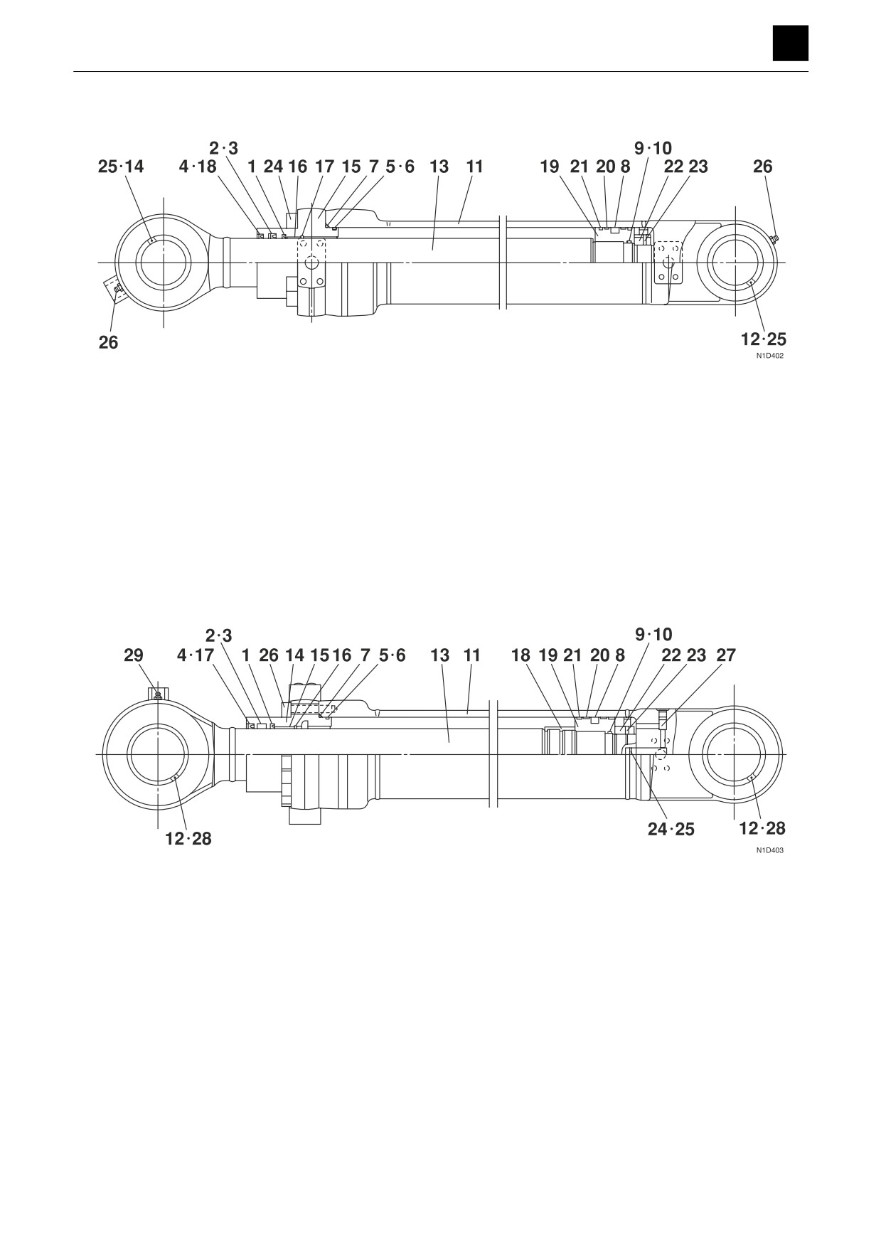
Bucket cylinder
1. Buffer ring
8. Piston packing
15. Rod cover
22. Nut
2. Rod packing
9. O-ring
16. Bushing
23. Set screw
3. Backup ring
10. Backup ring
17. Snap ring
24. Cap screw
4. Dust seal
11. Tube
18. Snap ring
25. Dust seal
5. O-ring
12. Bushing
19. Piston
26. Grease nipple
6. Backup ring
13. Piston rod
20. Wear ring
7. O-ring
14. Bushing
21. Dust ring
Swing cylinder
1. Buffer ring
8. Piston packing
15. Rod cover
22. Dust ring
2. Rod packing
9. O-ring
16. Bushing
23. Nut
3. Backup ring
10. Backup ring
17. Snap ring
24. Set screw
4. Dust seal
11. Tube
18. Snap ring
25. Cap screw
5. O-ring
12. Bushing
19. Cushion bearing
26. Dust seal
6. Backup ring
13. Piston rod
20. Piston
27. Grease nipple
7. O-ring
14. Bushing
21. Wear ring
28. Grease nipple
2
CYLINDERS
4L0AS00
DISASSEMBLY AND ASSEMBLY
4
CYLINDERS
Dozer blade cylinder
1. Buffer ring
10. Tube
18. Wear ring
2. Rod packing
11. Bushing
19. Dust ring
3. Dust seal
12. Piston rod
20. Nut
4. O-ring
13. Rod cover
21. Set screw
5. Backup ring
14. Bushing
22. Dust seal
6. O-ring
15. Snap ring
23. Grease nipple
7. Piston packing
16. Snap ring
24. Grease nipple
8. O-ring
17. Piston
3
CYLINDERS
4L0AS00
DISASSEMBLY AND ASSEMBLY
4
CYLINDERS
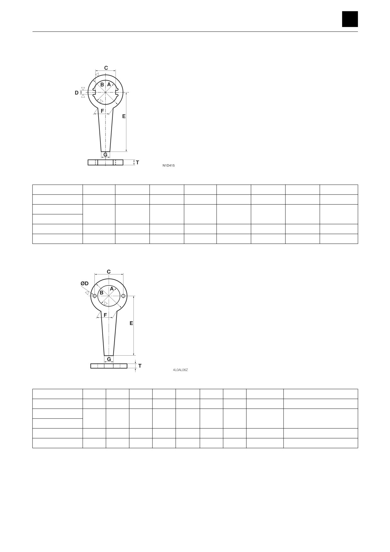
Special tools
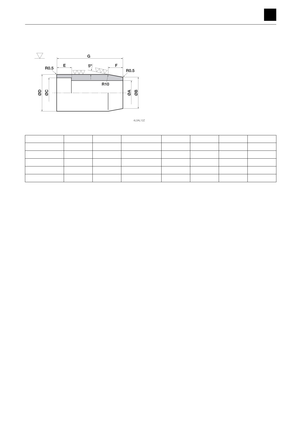
Special wrench (For the piston nut)
Unit: mm
Cylinders
A
B
C
D
E
F
G
T
Arm
90
150
80
11
300
70
40
12 to 15
Boom
80
130
70
11
300
70
40
12 to 15
Bucket
Swing
99
159
89
11
300
70
40
12 to 15
Dozer blade
85
140
75
11
300
70
40
12 to 15
Special wrench (For the piston)
Unit: mm
Cylinders
A
B
C
D
E
F
G
T
Combined bolts
Arm
65
115
85
10
300
70
40
12 to 15
M8×20 (Qty. 2)
Boom
55
105
75
11
300
70
40
12 to 15
M10×20 (Qty. 2)
Bucket
Swing
80
150
110
14
300
70
40
12 to 15
M12×20 (Qty. 2)
Dozer blade
60
110
80
12
300
70
40
12 to 15
M10×20 (Qty. 2)
4
CYLINDERS
4L0AS00
DISASSEMBLY AND ASSEMBLY
4
CYLINDERS
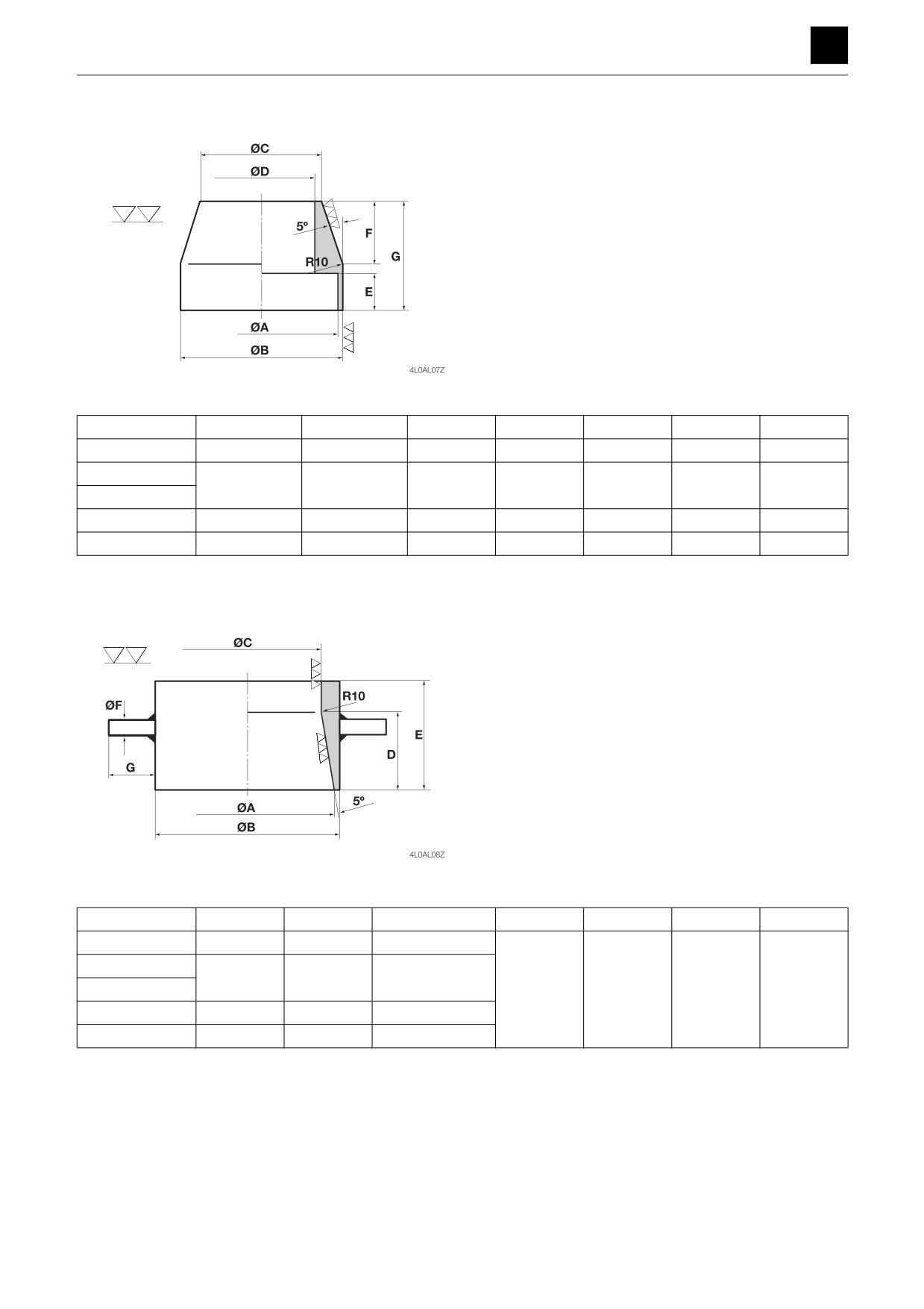
Installation jig (For the piston seals)
Unit: mm
Cylinders
A
B
C
D
E
F
G
Arm
109.5 ± 0.1
111 ± 0.1
100
90
22.0
63
90
Boom
99.5 ± 0.1
101 ± 0.1
90
80
23.0
63
90
Bucket
Swing
139.5 ± 0.1
141 ± 0.1
130
120
26.0
63
94
Dozer blade
114.5 ± 0.1
116 ± 0.1
105
95
28.0
63
96
Corrective jig (For the piston seals)
Unit: mm
Cylinders
A
B
C
D
E
F
G
Arm
120
128
112 ± 0.1
Boom
110
118
102 ± 0.1
Bucket
46
75
10 to 15
100
Swing
150
158
142 ± 0.1
Dozer blade
125
133
117 ± 0.1
5
CYLINDERS
4L0AS00
DISASSEMBLY AND ASSEMBLY
4
CYLINDERS
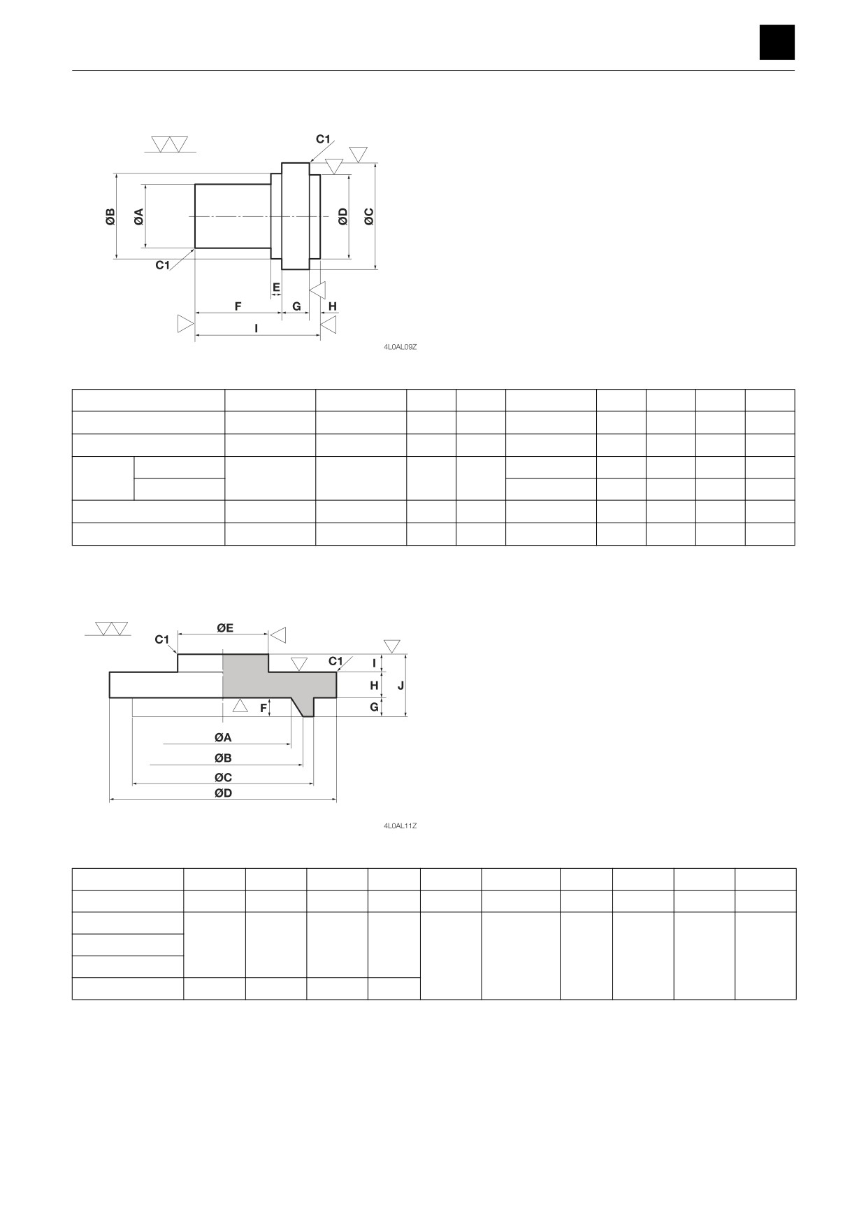
Press-fitting jig (For the pin bushing)
Unit: mm
Cylinders
A
B
C
D
E
F
G
H
I
0
Arm
79.5
-0.1
94.5 ± 0.1
115
95
6.5 ± 0.1
90
20
10
120
Boom
74.5
0-0.1
89.5 ± 0.1
110
90
5.5 ± 0.1
95
20
10
125
Rod side
5.0 ± 0.1
90
20
10
120
0
Bucket
64.5
-0.1
79.5 ± 0.1
100
80
Head side
4.5 ± 0.1
85
20
10
115
0
Swing
99.5
-0.1
114.5 ± 0.1
135
115
4.5 ± 0.1
115
20
10
145
Dozer blade
69.5
0-0.1
84.5 ± 0.1
105
85
6.0 ± 0.1
75
20
10
105
Press-fitting jig (For the dust seals)
Unit: mm
Cylinders
A
B
C
D
E
F
G
H
I
J
Arm
85
88
93
108
80
5
5.5
15
5
25.5
Boom
Bucket
75
78
83
98
80
5
5.0
15
5
25
Dozer blade
Swing
95
98
103
118
6
CYLINDERS
4L0AS00
DISASSEMBLY AND ASSEMBLY
4
CYLINDERS
Installation jig (For the rod cover)
Unit: mm
Cylinders
A
B
C
D
E
F
G
0
Arm
70.5
75
75.3 ± 0.1
80
-0.1
32
28.5
155
Boom
60.5
65
65.3 ± 0.1
700
-0.1
22
28.5
145
0
Bucket
60.5
65
—
70
-0.1
—
28.5
110
Swing
80.5
85
85.3 ± 0.1
900
-0.1
32
28.5
180
0
Dozer blade
65.5
67
—
70
-0.1
—
17
105
7
CYLINDERS
4L0AS00
DISASSEMBLY AND ASSEMBLY
4
CYLINDERS
Disassembly and assembly
This section provides a description of procedures mainly
for standard cylinders. Complete actual work proce-
dures while studying the construction of the parts provid-
ed in this section.
The numbers in parentheses, ( ), listed after the names of
parts throughout this document do not necessarily match
the numbers of the same parts listed in the construction
diagrams and parts lists. The numbers listed are for part
numbers used in illustrations.
General precautions
•
Perform disassembly and assembly work in a clean
place. Provide clean containers to hold parts during
disassembly.
•
Clean around the ports before disassembly. Remove
paint around connectors with a wire brush.
•
Clean the disassembled parts with wash oil.
•
Put alignment marks on all parts to ensure that they are
reassembled in the same positions.
•
After each disassembly, replace all seals and apply a
thin layer of grease to each.
•
Check each part for abnormal wear or seizing. Re-
move any burrs with sandpaper.
•
Remove adhesive from screw holes that use adhesive
through the tap. Do not reuse mounting bolts or
screws.
•
Do not use cloth gloves during assembly. Fibers from
the gloves could fall off and clog valves, etc., which
could cause parts to become faulty.
•
During assembly, be sure to apply clean hydraulic oil
to all moving parts in and sliding parts that come into
contact with the hydraulic motor and valve parts be-
fore installing or attaching the part.
•
Plug all ports once assembly has been completed in
order to prevent dust and dirt from entering.
•
Do not attempt to adjust the adjusting screws at times
other than when necessary.
Disassembly
Cylinder assembly
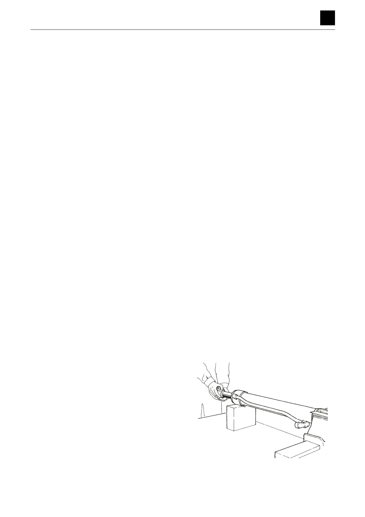
1. Secure the cylinder horizontally by securing the cle-
vis of the tube in a vice and placing a wooden sup-
port under the other end.
2. Drain out any hydraulic oil left remaining in the cylin-
der.
• Move the piston rod slowly to prevent the hydrau-
lic oil from spraying out.
4LAA07Z
8
CYLINDERS
4L0AS00
DISASSEMBLY AND ASSEMBLY
4
CYLINDERS
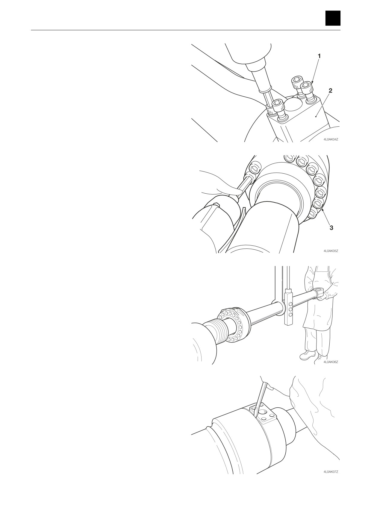
3. Loosen the cap screw (1), and remove the pipe (2).
4. Take out the cap screw (3) in the rod cover.
• Cover the piston rod to prevent it from becoming
damaged.
5. Remove the piston rod assembly (4) from the tube
(5).
a. Raise and temporarily suspend the rod with a
crane such that the rod and tube are straight.
b. Tap the end corner of the pipe port flange to cre-
ate a clearance.
c. Insert the end of a flat-bladed screwdriver into the
clearance to widen the clearance further.
d. Remove the piston rod assembly from the tube.
• Pull it straight out so as not to damage sliding
surfaces.
9
CYLINDERS
4L0AS00
DISASSEMBLY AND ASSEMBLY
4
CYLINDERS
Cylinder assembly (Blade cylinder)
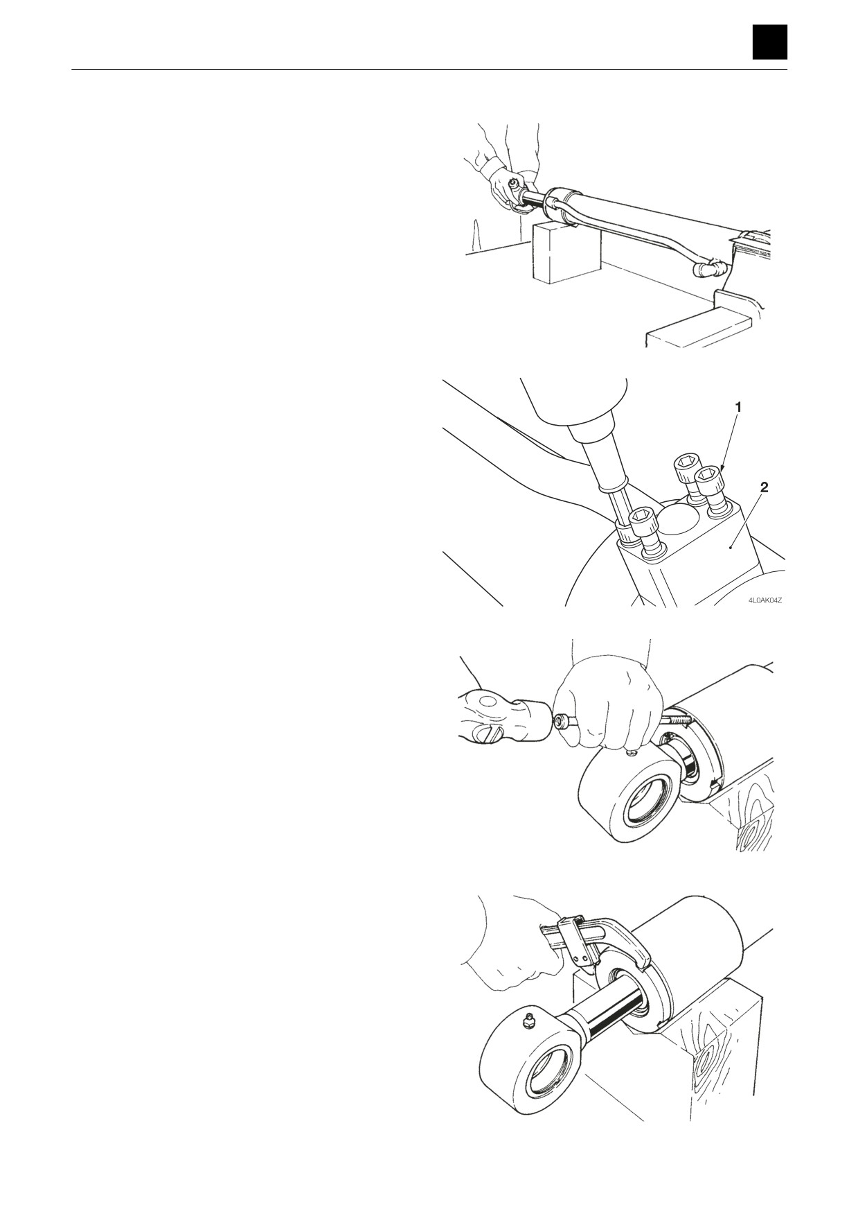
1. Secure the cylinder horizontally by securing the cle-
vis of the tube in a vice and placing a wooden sup-
port under the other end.
2. Drain out any hydraulic oil left remaining in the cylin-
der.
• Move the piston rod slowly to prevent the hydrau-
lic oil from spraying out.
4LAA07Z
3. Loosen the cap screw (1), and remove the pipe (2).
4. Disengage the anti-rotation lock for the rod cover.
• As the anti-rotation lock is built directly into the
cylinder tube, take care not to damage the tube
when releasing the lock.
4LAA08Z
5. Loosen the rod cover.
• Pull the piston rod outward about 200 mm (7.9 in.)
in advance.
• Cover the piston rod to prevent it from becoming
damaged.
6. Remove the piston rod assembly from the tube.
• Pull it straight out so as not to damage sliding sur-
faces.
4LAA09Z
10
CYLINDERS
4L0AS00
DISASSEMBLY AND ASSEMBLY
4
CYLINDERS
Piston rod assembly
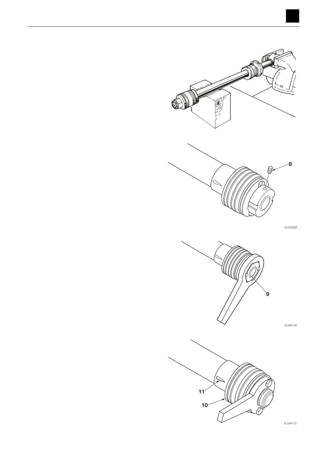
1. Secure the piston rod assembly horizontally.
4LAA10Z
2. Remove the piston section.
a. Take out the set screw (8).
• The set screw (8) is swaged with a punch in two
places. Apply oil while gently loosening it.
b. Remove the piston nut
(9) using the special
wrench (for the piston nut).
c. Remove the piston (10) using the special wrench
(for the piston).
11
CYLINDERS
4L0AS00
DISASSEMBLY AND ASSEMBLY
4
CYLINDERS
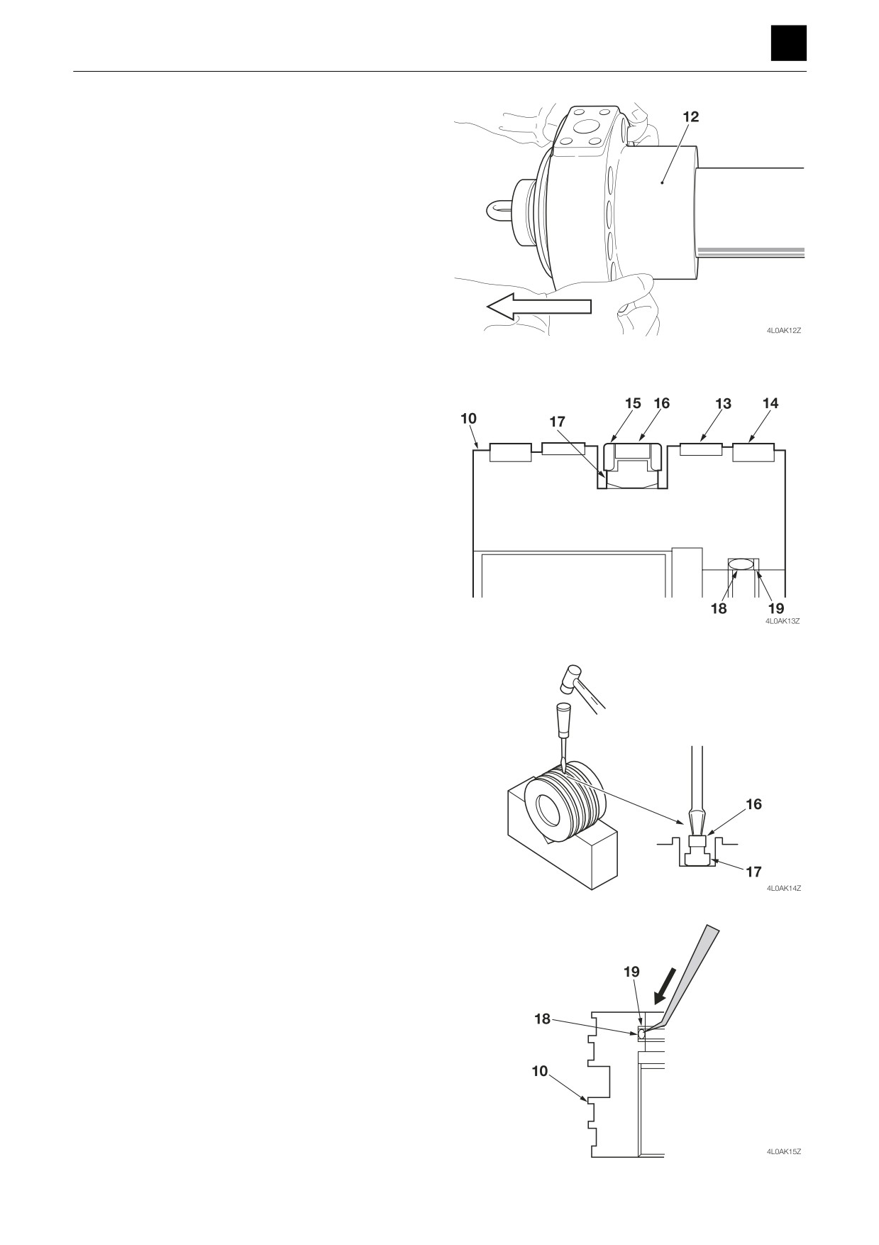
3. Remove the rod cover assembly (12) from the rod.
Piston
1. Remove the wear ring (13) and dust ring (14) from
the piston (10).
2. Remove the piston seals.
a. Remove the backup ring (15).
b. Remove the seal ring (16) and backup ring (17).
• Secure the piston so that it does not move, and
remove the seal ring and backup ring using a
flat-bladed screwdriver and a hammer.
3. Remove the O-ring (18) and backup ring (19) from
the inside of the piston.
• Use a spatula to scrape away the rings.
12
CYLINDERS
4L0AS00
DISASSEMBLY AND ASSEMBLY
4
CYLINDERS
Rod cover
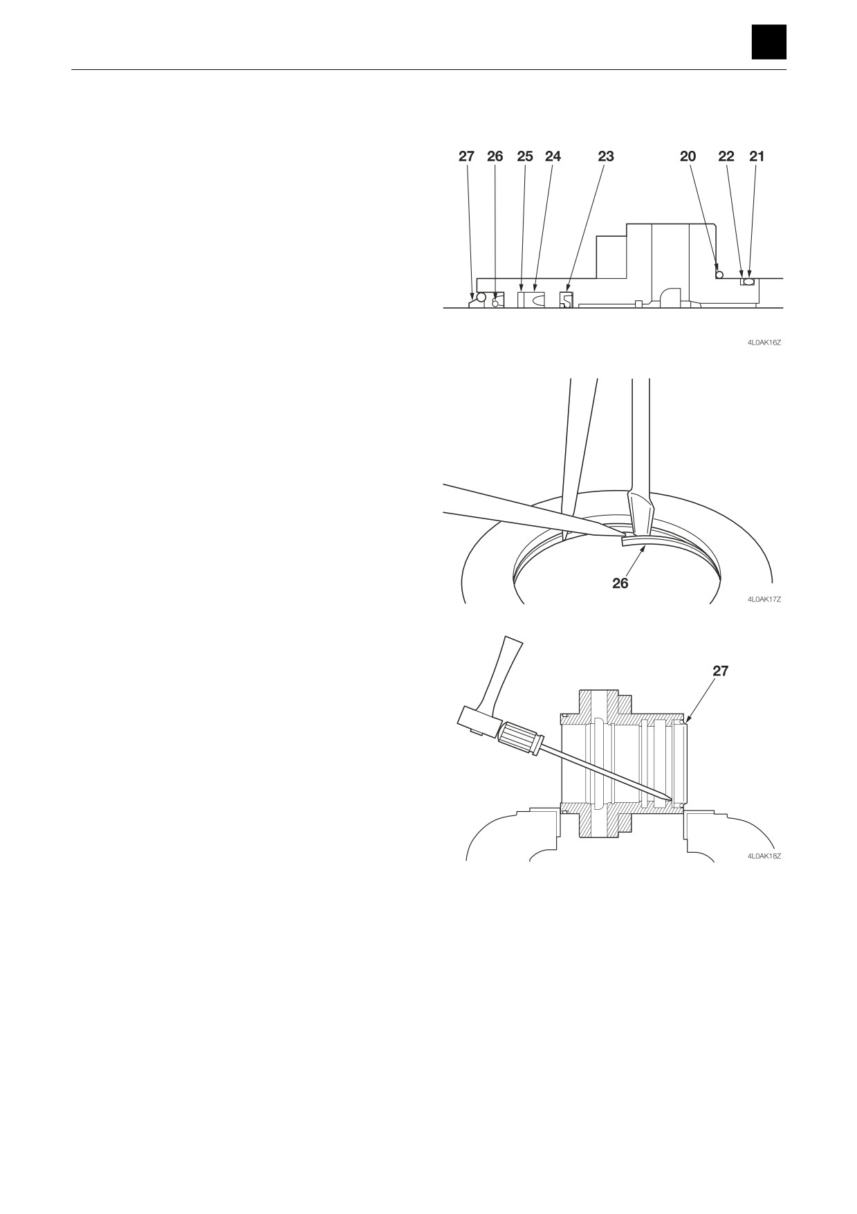
1. Remove the O-rings (20) and (21) and backup ring
(22) from the rod cover.
2. Remove the buffer seal (23) and rod packing (24).
3. Remove the retaining ring (26).
4. Remove the dust seal (27).
a. Place the rod cover in a vice.
b. Insert the blade of a flat-bladed screwdriver into
the groove on the dust seal, and tap the screw-
driver with a hammer to remove the seal.
5. Scrape away the bushing to remove it.
• Do not remove the bushing unless it is badly dam-
aged by wear or seizing.
13
CYLINDERS
4L0AS00
DISASSEMBLY AND ASSEMBLY
4
CYLINDERS
Clevises
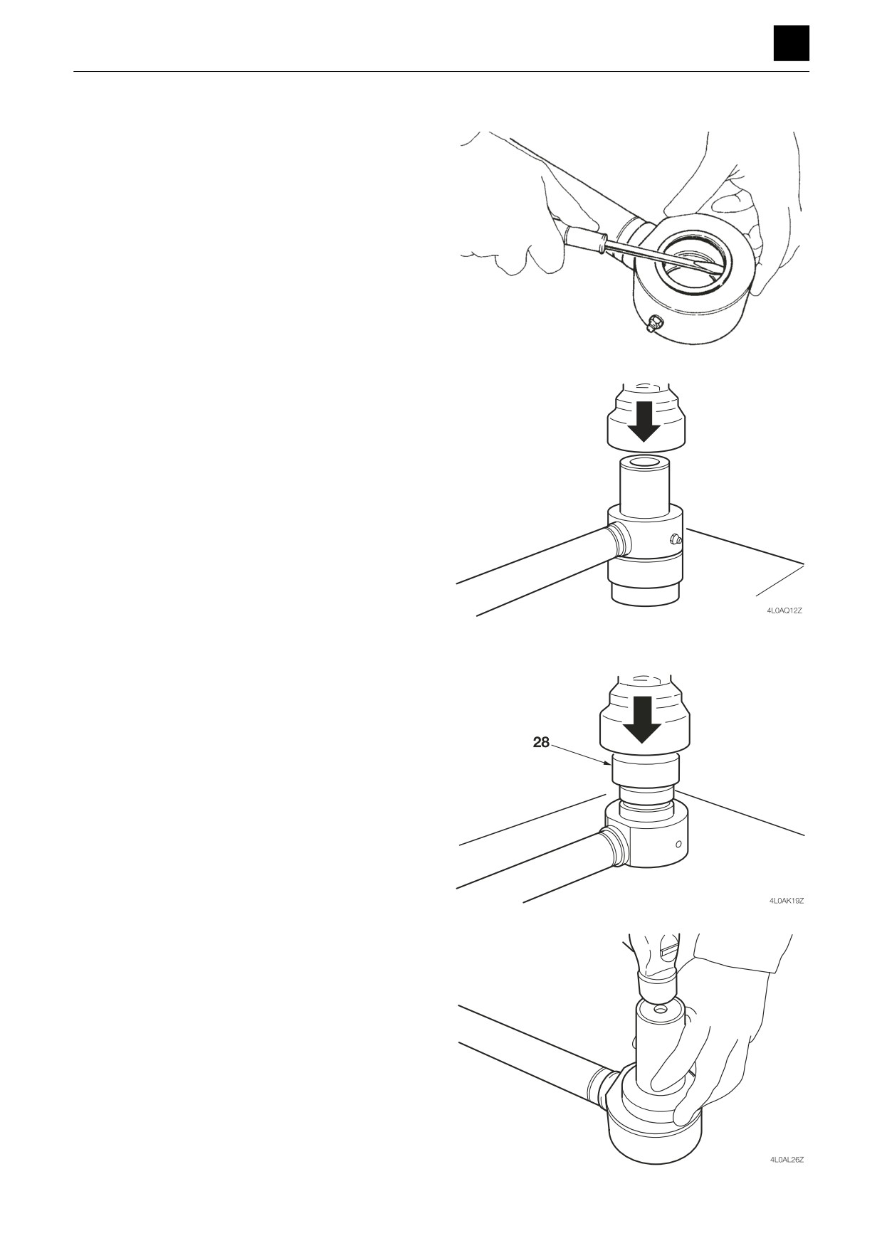
1. Remove the dust seals from the clevises of the tube
and piston rod.
4LAA22Z
2. Remove the bushing from the piston rod.
• Pull out the bushing using a press with a support-
ing metal plate.
Assembly
Clevises
1. Press-fit the bushing into the piston rod and tube.
• Complete using the press-fitting jig (28) (for the
bushing).
2. Attach the dust seal using a press with a supporting
metal plate.
14
CYLINDERS
4L0AS00
DISASSEMBLY AND ASSEMBLY
4
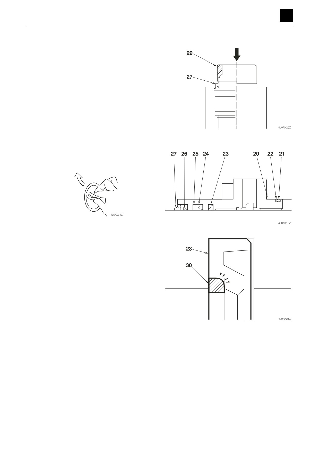
CYLINDERS
Rod cover
1. Attach the dust seal (27).
• Use the press-fitting jig (29) (for the dust seal) to
press-fit the dust seal into the cover to ensure that
an equal amount of pressure is applied around
the circumference of the dust seal.
• Apply grease to the inner sides of the dust seal.
2. Attach the buffer ring (23), rod packing (24), and
backup ring (25).
• Shape the seal into a heart, and insert it from the
direction of the arrow side.
• Position the R part on the backup ring (30) for the
buffer ring (23) as shown in the diagram.
3. Attach the O-ring (20).
4. Attach the O-ring (21) and backup ring (22).
15
CYLINDERS
4L0AS00
DISASSEMBLY AND ASSEMBLY
4
CYLINDERS
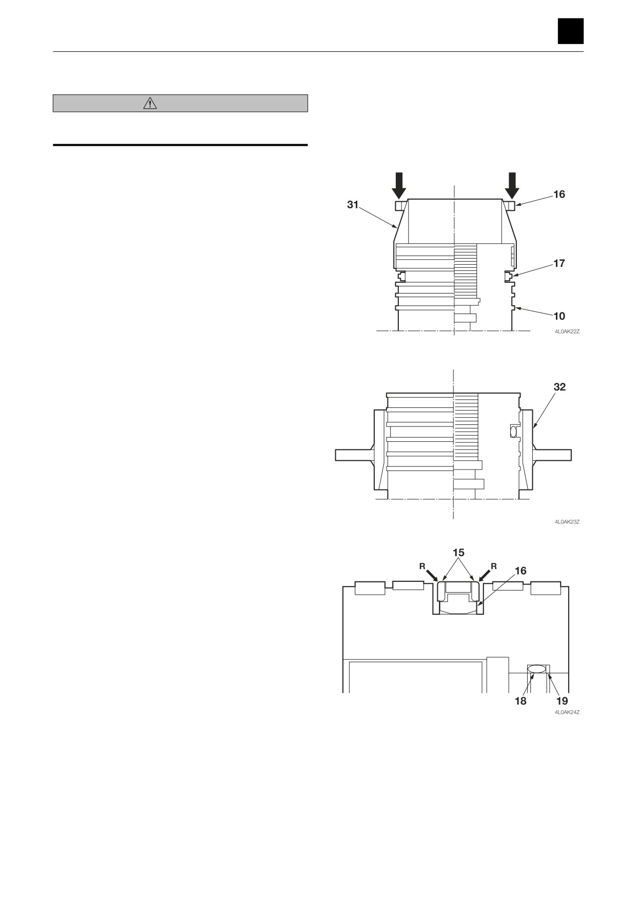
Piston
WARNING
Wear gloves when completing this procedure to keep
from getting burned on the heated seal ring.
1. Insert the back ring (17) into the piston.
2. Place the special jig (for the piston seal) (31) onto the
piston, and use it to attach the seal ring (16).
• Heat the hydraulic oil to a temperature of around
150°C to 180°C (302°F to 356°F) using an electri-
cal heater, and dip the seal ring into the heated oil
for five minutes and then attach it to the back ring
while it is still warm.
3. Correct the shape and length of the seal ring using
the corrective jig (for the piston seal) (32) as the seal
ring may become stretched during attachment.
4. Attach the backup ring (15) to both sides of the seal
ring (16).
• Position the R part on the backup ring as shown in
the diagram.
5. Attach the O-ring (18) and backup ring (19).
16
CYLINDERS
4L0AS00
DISASSEMBLY AND ASSEMBLY
4
CYLINDERS
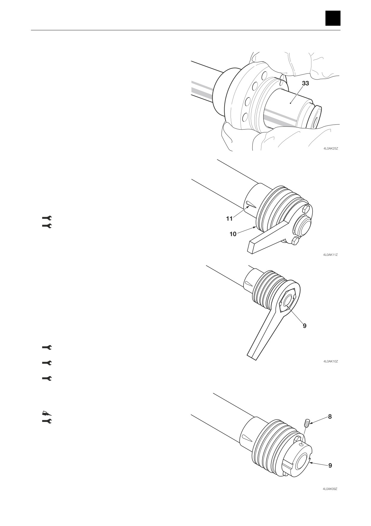
Piston rod assembly
1. Attach the rod cover assembly to the piston rod.
• Secure the piston rod assembly horizontally.
• Use the installation jig (33) (for the rod cover) to
attach the rod cover assembly.
• Apply hydraulic oil to the surfaces of the installa-
tion jig and rod.
2. Attach the piston to the piston rod.
• Attach the piston together with the cushion ring if
using a cushion ring.
• Use the special wrench (for the piston) to attach
the piston.
• Gently tighten the piston taking care not to tighten
it too far.
Piston (Blade cylinder): 735 N·m ± 69 N·m
Piston (Other cylinders): 981 N·m ± 98 N·m
3. Fasten on the piston nut (9).
• Use the special wrench (for the piston nut) to
screw on the piston nut.
• Gently tighten the piston nut taking care not to
tighten it too far.
• If using a cushion ring, after fastening on the pis-
ton nut, do not tighten down the cushion ring but
instead leave a clearance of around 0.5 mm (0.02
in.) in the direction of the shaft, and check to en-
sure that the cushion ring moves freely.
Piston nuts (For the arm, boom, and bucket cyl-
inders): 1274 N·m ± 127 N·m
Piston nut (For the swing cylinder): 1860 N·m ±
186 N·m
Piston nut (For the blade cylinder): 1274 N·m ±
130 N·m
4. Fasten on the set screw (8) and swage it into place
in two places using a punch.
Set screw: Apply Loctite #242.
Set screw: 15 N·m ± 1.5 N·m
17
CYLINDERS
4L0AS00
DISASSEMBLY AND ASSEMBLY
4
CYLINDERS
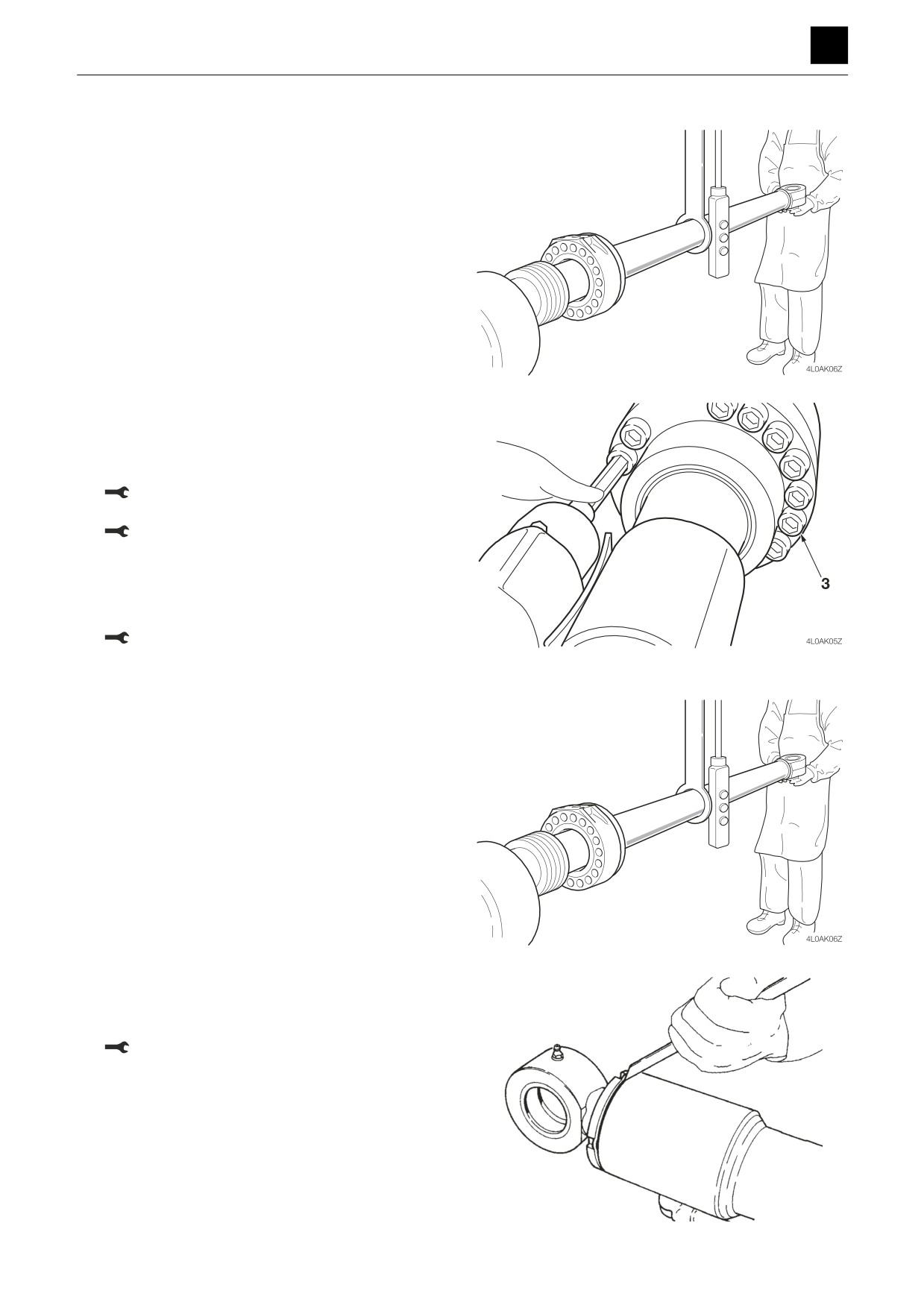
Cylinder assembly
1. Secure the tube horizontally, and insert the piston
rod assembly into the tube.
• Insert the tube straight into the piston rod, lining
up the center of the tube with the center of the pis-
ton rod shaft.
2. Attach the rod cover, and fasten it in place with the
cap screw (3).
• Make sure that the pipe flange of the rod cover is
oriented properly when attaching the rod cover.
Cap screws (Arm, boom, and bucket cylinders):
211 N·m ± 5 N·m
Cap screw (Swing cylinder): 353 N·m ± 10 N·m
3. Insert the check valves (for the arm cylinder, swing
cylinder).
• Attach parts in order of valve, spring, spring re-
tainer, and then plug with attached O-ring.
Plug: 49.0 N·m ± 4.9 N·m
Cylinder assembly (Blade cylinder)
1. Secure the tube horizontally, and insert the piston
rod assembly into the tube.
• Insert the tube straight into the piston rod, lining
up the center of the tube with the center of the pis-
ton rod shaft.
2. Attach the rod cover and tighten it down with screws.
• Make sure that the pipe flange of the rod cover is
oriented properly when attaching the rod cover.
Rod cover: 588 N·m ± 98 N·m
3. Bend the lock rib on the tube and lock it into place.
4LAA36Z
18
CYLINDERS
4L0AS00
DISASSEMBLY AND ASSEMBLY
4
CYLINDERS
Inspection and adjustments
Inspection after disassembly
Clean each part thoroughly with cleaning oil, then carry
out the following checks. When a cylinder has been dis-
assembled, replace all the seals with new ones.
1. Piston rod
• Replace the rod if it has any cracks.
• Repair any damaged threads, or replace the rod
entirely if there are damaged threads.
• Replace the rod if the plating layer of the plated
portion is broken, rusted, or scratched.
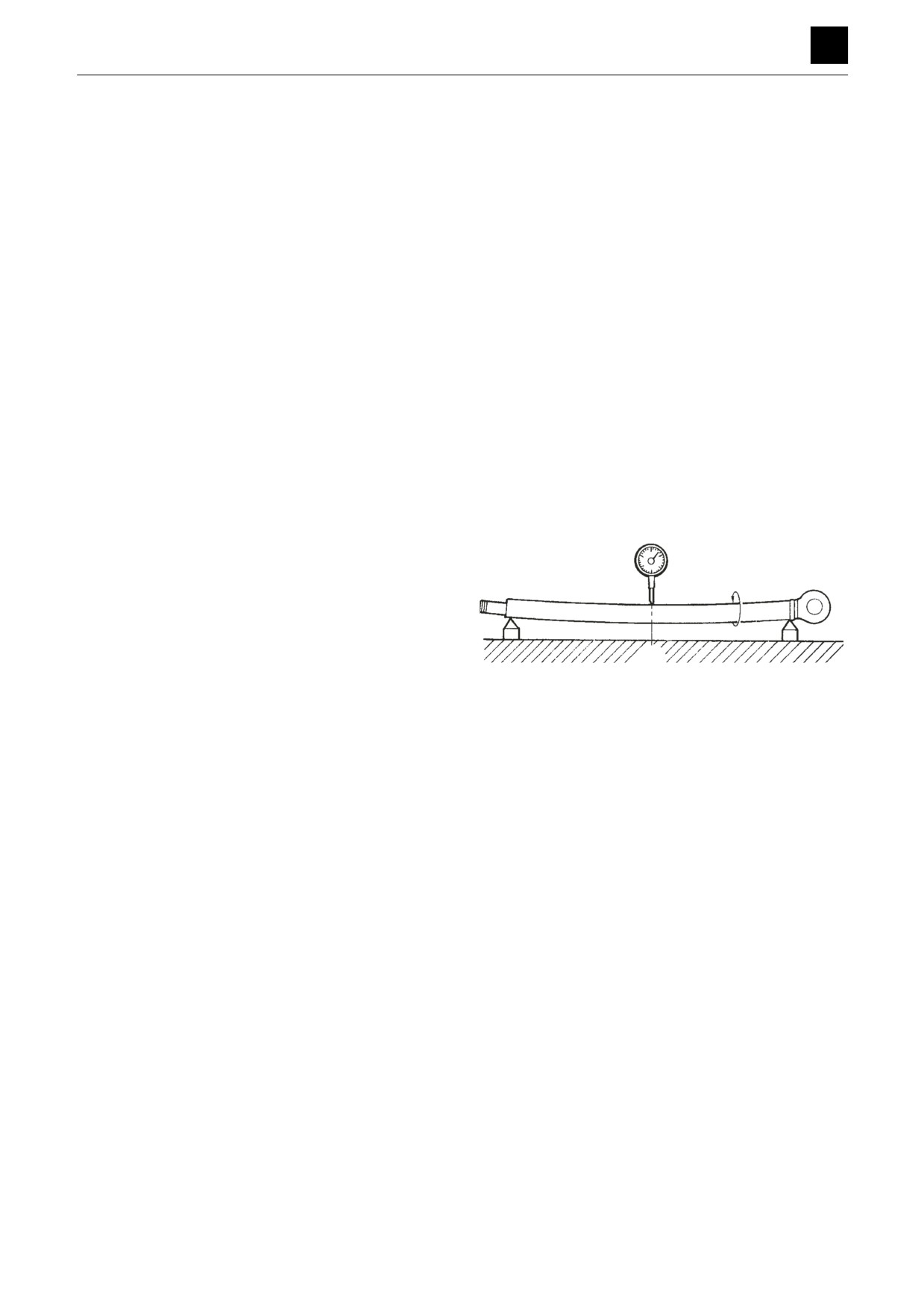
• Replace the rod if it is bent by more than the limit
of 1 mm in 1 m. (For the measurement method, re-
fer to the figure on the right.)
• Replace the bushing if the inner diameter of the
clevis bushing is worn.
Measuring the bend
a. Place the portion of the rod with the same diame-
ter at both ends on V-blocks to support it.
b. Place a dial gauge at the center point between the
two blocks.
c. Rotate the rod, and record the readings for maxi-
mum and minimum run-out shown on the dial
gauge.
If the amount of bending in the rod is within the
above limit but is great across a short distance so
1/2
that the rod does not move smoothly, replace the
rod if it makes a squeaking sound during the op-
eration test after reassembly or if it catches during
4LAA37Z
movement.
2. Tube
• Replace the tube if there are cracks in the welded
portion.
• Replace the tube if the inside surface is scratched
or if it leaks hydraulic oil.
• Replace the bushing if the inner diameter of the
clevis bushing is worn.
3. Rod cover
• Replace the bushing if the bushing inner diameter
is worn and the clearance with the piston rod is
greater than 0.25 mm (0.0098 in.).
• Replace the bushing if the inside surface of the
bushing is scratched and the scratches penetrate
beyond the coating layer.
19
CYLINDERS
4L0AS00
DISASSEMBLY AND ASSEMBLY
4
CYLINDERS
Inspection after assembly
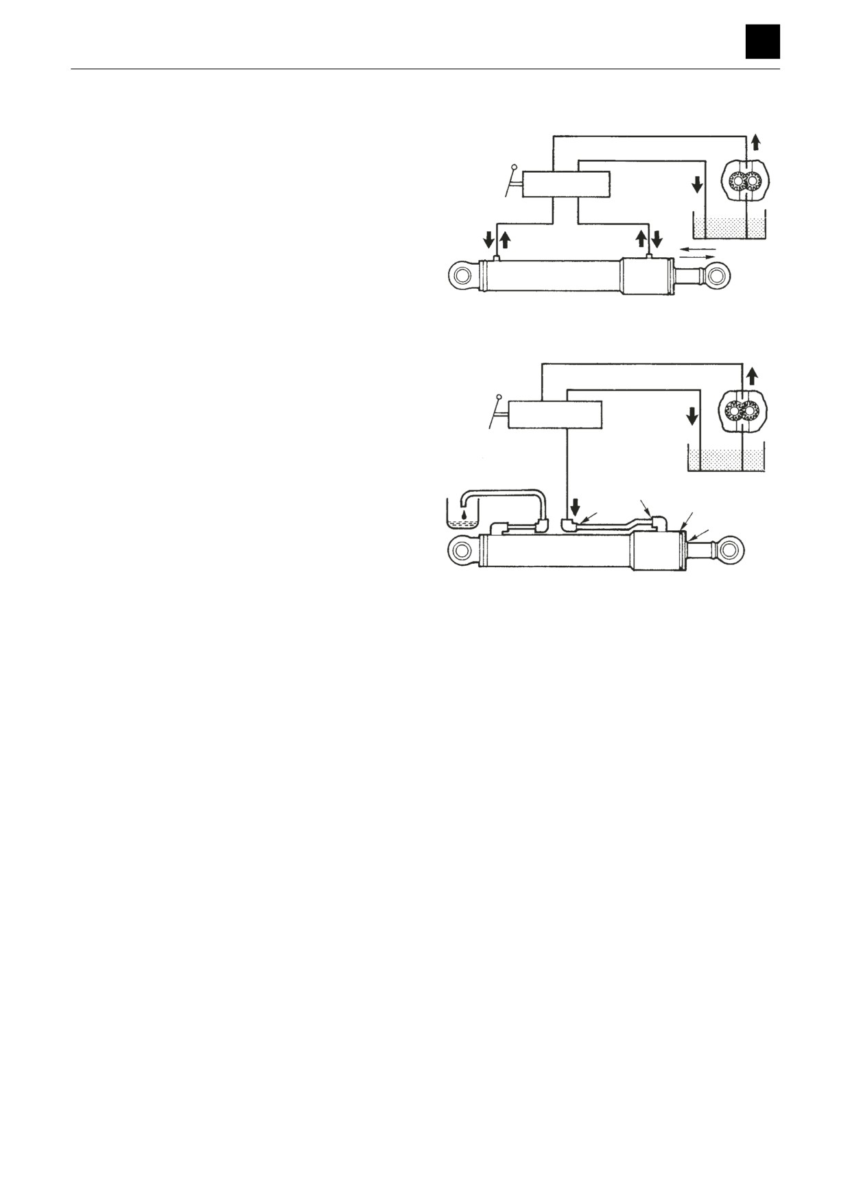
No load operation test
1. Place the cylinder in a horizontal position with no
load.
2. Apply gentle pressure alternately to the ports at the
ends, and operate the piston rod 5 or 6 times.
3. Make sure that there are no errors or abnormal oper-
ating conditions.
4LAA38Z
Leak test
• External leak
1. Apply a test pressure to the retraction side and to the
extension side for 3 minutes each.
2. Make sure that there are no abnormalities such as
external leakage or permanent deformation, etc. in
the rod seal or rod cover mount or in any welded por-
tion.
• Internal leak
1. Disconnect the hose on the extension side.
4LAA39Z
2. Apply the test pressure to the retraction side for 3
minutes.
3. Measure the amount of oil that has leaked from the
extension side.
• The amount of leakage should be 1 mL/3 min. or
less.
Bleeding air from the hydraulic cylinder
Bleed air out of the cylinder when the cylinder is removed
or when the hydraulic piping or other parts are discon-
nected.
1. Start the engine, and let it idle for approximately 5
minutes.
2. With the engine running at slow speed, extend and
retract the cylinder 4 or 5 times.
• Move the piston rod to a position 100 mm (3.94
in.) before the end of the stroke, being careful not
to relieve air.
3. With the engine running at top speed, repeat the op-
eration outlined in (2), and then, with the engine run-
ning at slow speed, move the piston rod to the stroke
end to bleed off the air in the cylinder.
20
CYLINDERS
4L0AS00
DISASSEMBLY AND ASSEMBLY
TRAVEL MOTOR 4
TRAVEL MOTOR
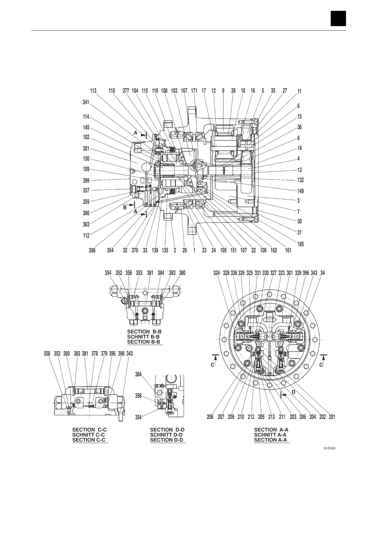
Construction
1
TRAVEL MOTOR
4M0AS00
DISASSEMBLY AND ASSEMBLY
TRAVEL MOTOR 4
1. Gear case
102. Driving shaft
205. Plug
376. Orifice
2. Motor housing
103. Swash plate
206. Spring
377. Filter
3. Carrier
104. Cylinder block
207. O-ring
378. Steel ball
4. Sun gear
105. Piston
208. Backup ring
379. Plug
5. Planet gear
106. Shoe
209. O-ring
380. Plug
6. Pin
107. Shoe holder
210. Backup ring
381. Piston
7. Carrier
108. Guide
211. O-ring
383. O-ring
8. Sun gear
109. Valve plate
212. O-ring
384. Orifice
9. Planet gear
110. Washer
213. Shim
396. Plug
10. Pin
112. Break piston
301. Valve body
398. Plug
11. Thrust washer
113. Spring
323. Spool
399. Plate
12. Thrust washer
114. Spring
324. Plug
13. Thrust plate
115. Friction disc
325. Washer
14. Cover
116. Center disc
326. Plug
15. Coupling
132. Oil seal
327. Valve
16. Pin
135. O-ring
328. Spring
17. Pin
139. O-ring
329. Orifice
22. Lock washer
145. Retaining ring
330. Spring
23. Shim
149. Bearing
331. O-ring
24. Angular bearing
150. Bearing
336. O-ring
27. Bearing
151. Pin
341. Pin
28. Bearing
161. Piston
343. Cap screw
29. Floating seal
162. Shoe
352. Plug
30. Plug
167. Pivot
353. Ball
31. O-ring
171. Pin
354. Plug
32. O-ring
185. Spring
357. Plug
33. O-ring
201. Valve seat
358. O-ring
34. Pin
202. Valve
359. O-ring
35. Cap screw
203. Sleeve
363. Spool
36. Retaining ring
204. Collar
366. Spring
2
TRAVEL MOTOR
4M0AS00
DISASSEMBLY AND ASSEMBLY
TRAVEL MOTOR 4
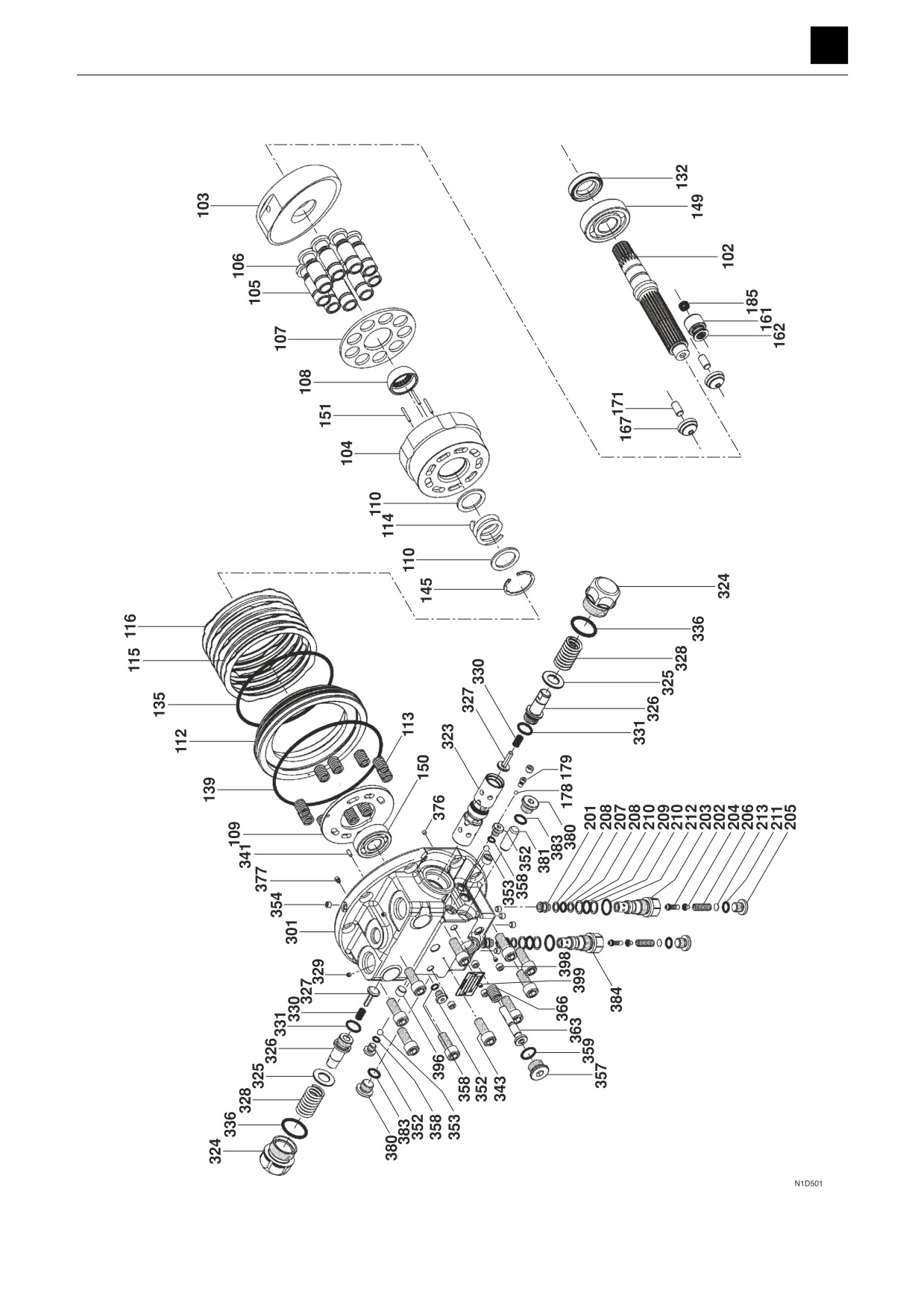
Brake valve, Hydraulic motor
3
TRAVEL MOTOR
4M0AS00
DISASSEMBLY AND ASSEMBLY
TRAVEL MOTOR 4
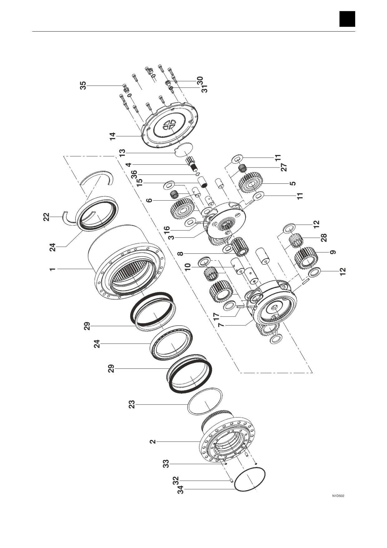
Reduction gears
4
TRAVEL MOTOR
4M0AS00
DISASSEMBLY AND ASSEMBLY
TRAVEL MOTOR 4
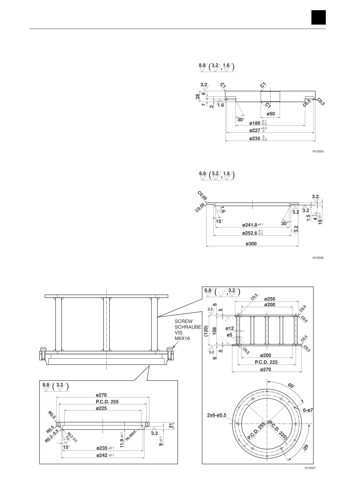
Special tools
Unit: mm
Press-fitting jig (A)
Inserting jig (B)
Inserting jig (C)
5
TRAVEL MOTOR
4M0AS00
DISASSEMBLY AND ASSEMBLY
TRAVEL MOTOR 4
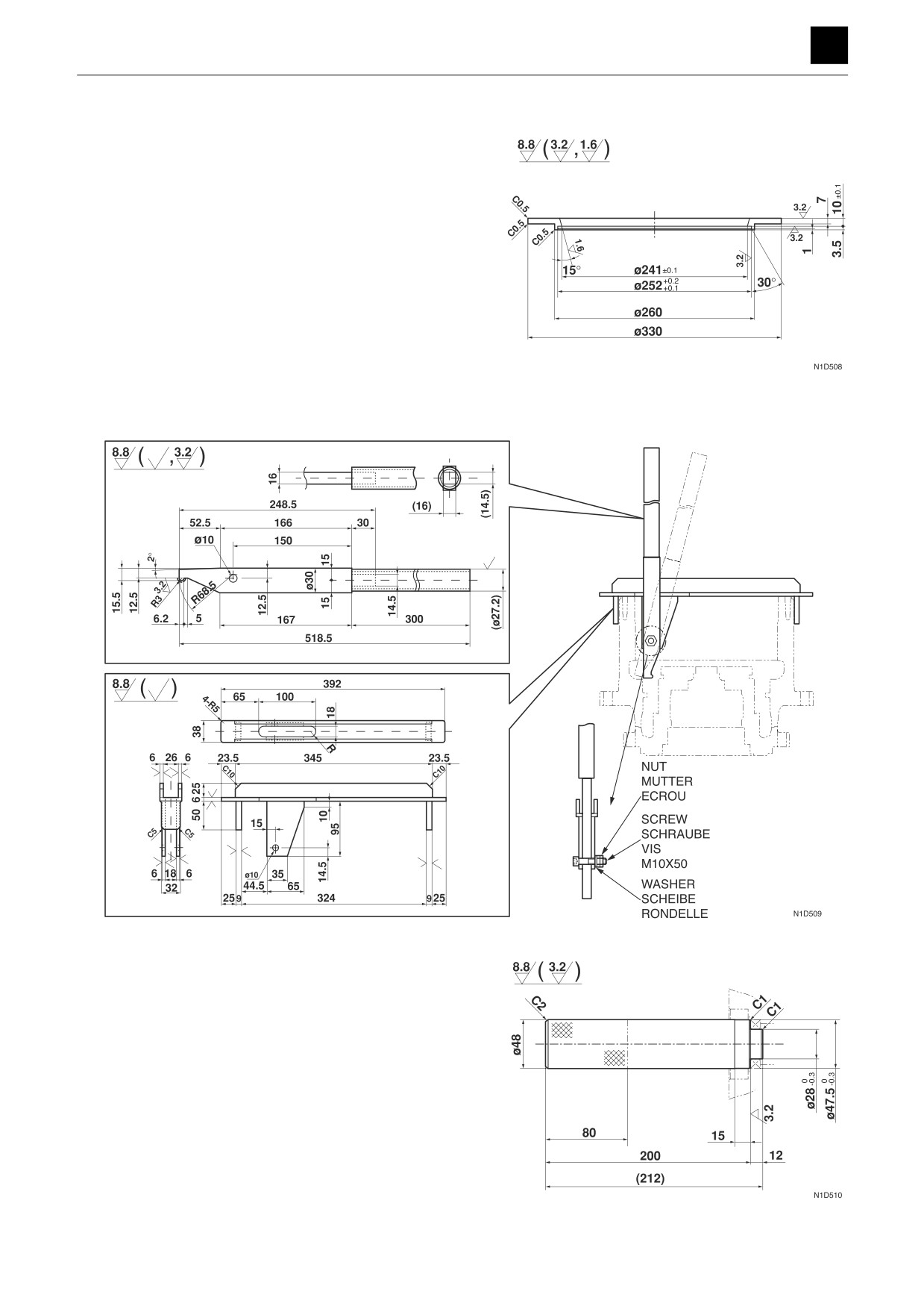
Unit: mm
Inserting jig (D)
Inserting jig (E)
Inserting jig (F)
6
TRAVEL MOTOR
4M0AS00
DISASSEMBLY AND ASSEMBLY
TRAVEL MOTOR 4
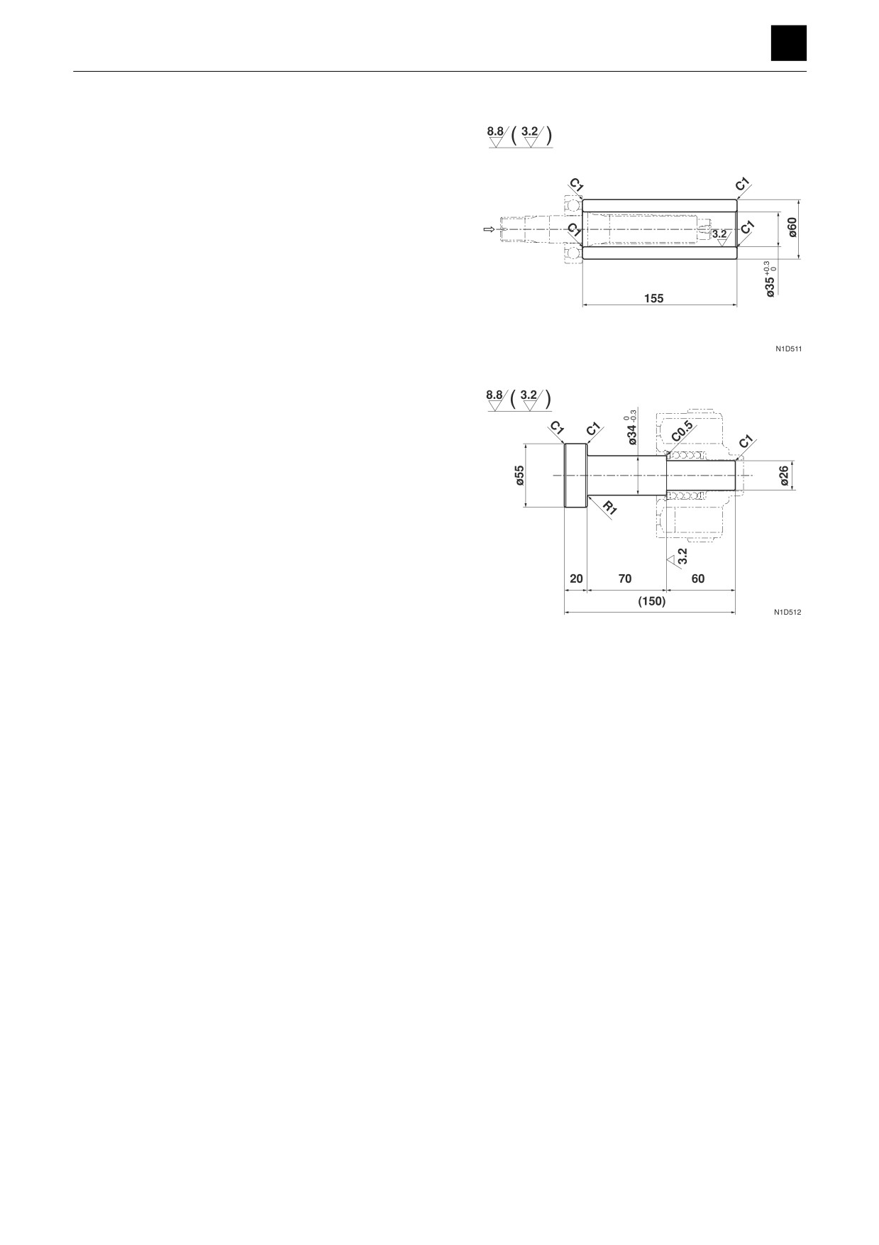
Unit: mm
Press-fitting jig (G)
Press-fitting jig (H)
7
TRAVEL MOTOR
4M0AS00
DISASSEMBLY AND ASSEMBLY
4
TRAVEL MOTOR
Disassembly and assembly
General precautions
•
Perform disassembly and assembly work in a clean
place. Provide clean containers to hold parts during
disassembly.
•
Clean around the ports before disassembly. Remove
paint around connectors with a wire brush.
•
Clean the disassembled parts with wash oil.
•
Put alignment marks on all parts to ensure that they are
reassembled in the same positions.
•
After each disassembly, replace all seals and apply a
thin layer of grease to each.
•
Check each part for abnormal wear or seizing. Re-
move any burrs with sandpaper.
•
Remove adhesive from screw holes that use adhesive
through the tap. Do not reuse mounting bolts or
screws.
•
Do not use cloth gloves during assembly. Fibers from
the gloves could fall off and clog valves, etc., which
could cause parts to become faulty.
•
During assembly, be sure to apply clean hydraulic oil
to all moving parts in and sliding parts that come into
contact with the hydraulic motor and valve parts be-
fore installing or attaching the part.
•
Plug all ports once assembly has been completed in
order to prevent dust and dirt from entering.
•
Do not attempt to adjust the adjusting screws at times
other than when necessary.
Disassembly
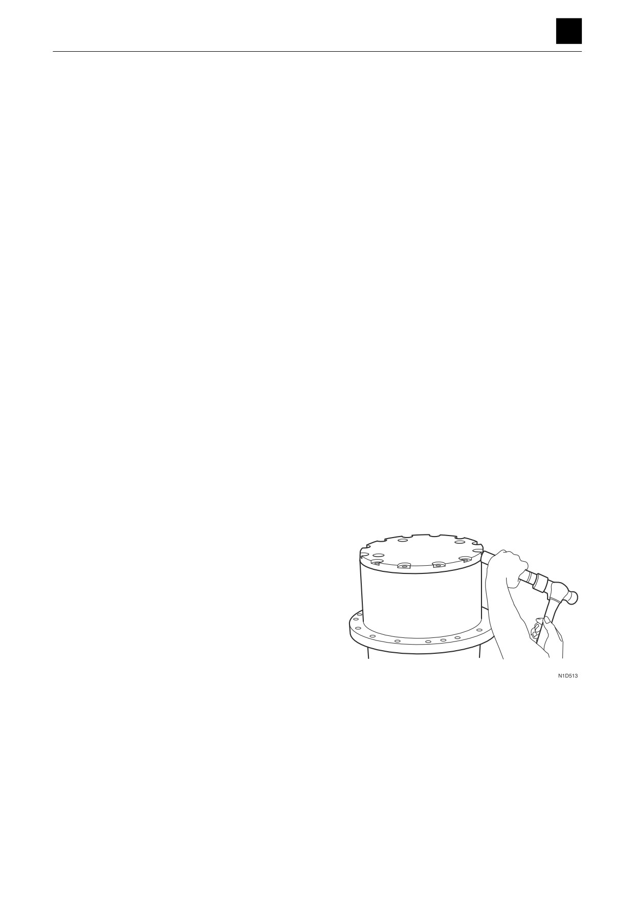
1. Remove the cover.
a. Take out the cap screws.
b. Place a supporting metal plate over the protrusion
on the cover, and tap the plate with a hammer.
8
TRAVEL MOTOR
4M0AS00
DISASSEMBLY AND ASSEMBLY
TRAVEL MOTOR 4
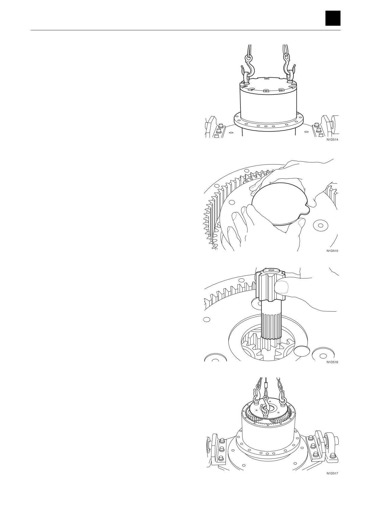
c. Install the i bolt and remove the cover.
2. Remove the thrust plate.
3. Remove the sun gear.
4. Remove the planet gear assembly.
9
TRAVEL MOTOR
4M0AS00
DISASSEMBLY AND ASSEMBLY
TRAVEL MOTOR 4
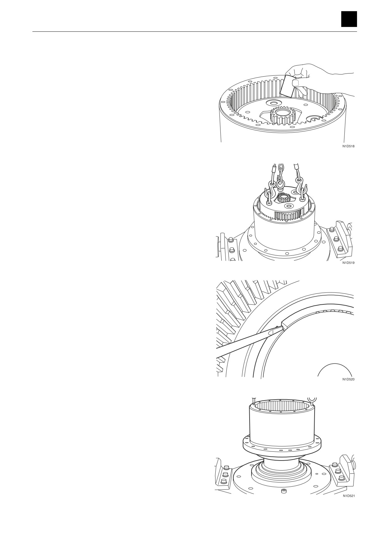
5. Remove the coupling.
6. Remove the planet gear assembly.
Remove the sun gear.
7. Remove the lock washers.
8. Remove the gear case.
10
TRAVEL MOTOR
4M0AS00
DISASSEMBLY AND ASSEMBLY
TRAVEL MOTOR 4
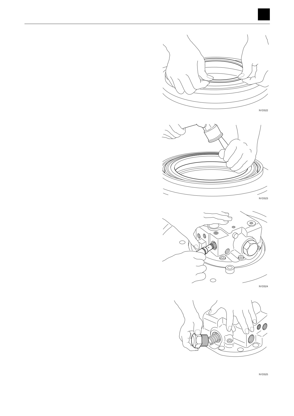
9. Remove the floating seal.
10. Remove the angular bearing.
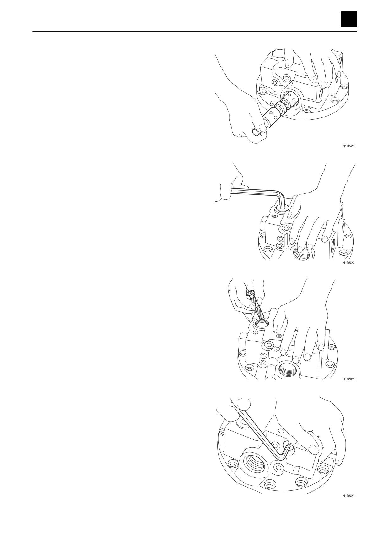
11. Remove the relief valve assemblies.
12. Remove the plugs.
Remove the springs and washers.
11
TRAVEL MOTOR
4M0AS00
DISASSEMBLY AND ASSEMBLY
TRAVEL MOTOR 4
13. Remove the spools.
14. Remove the plugs.
15. Remove the spools and springs.
16. Remove the plugs.
12
TRAVEL MOTOR
4M0AS00
DISASSEMBLY AND ASSEMBLY
TRAVEL MOTOR 4
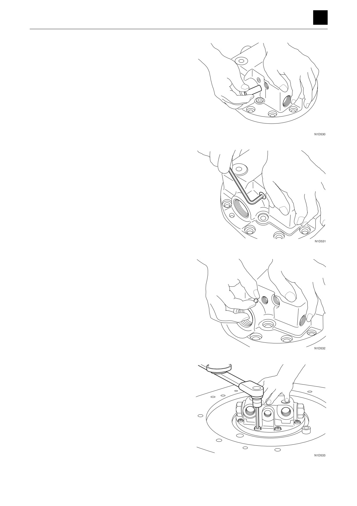
17. Remove the pistons.
18. Remove the plugs.
19. Remove the steel balls.
20. Take out the cap screws.
21. Remove the valve body.
13
TRAVEL MOTOR
4M0AS00