Takeuchi Hydraulic excavator TB1140 (Serial No. 514400002~). Operator's Manual - page 7
DISASSEMBLY AND ASSEMBLY
4
PILOT VALVE
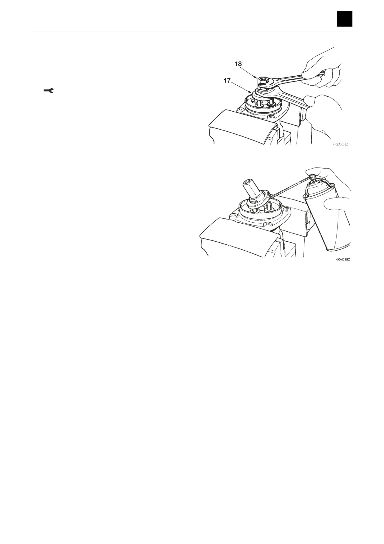
8. Use the nut (18) to affix the plate (17).
• Tighten the nut (18) to the point where plate con-
tacts all four rods uniformly.
• Do not allow the plate to move when tightening the
nut.
Nut: 68.6 N·m ± 4.9 N·m
9. Apply grease to the rotating parts on the joint (16)
and to the contact surfaces of the plate (17) and rods
(11).
10. Attach the handle (24) to the boot (23) and then at-
tach the boot (23).
8
PILOT VALVE
4K2AS00
DISASSEMBLY AND ASSEMBLY
4
PILOT VALVE
Inspection and adjustments
Inspection
Part
Criteria
Action
O-rings
—
•
Replace
Seals
—
•
Replace
Spool
• When the wear on the sliding portions is 10 μm (0.0004 in.) or greater
•
Replace
compared to non-sliding portions
• When there are scratches present on the sliding portions
•
Replace
• If the spool does not move smoothly enough
•
Replace
Rods
• If the front end is worn by 1 mm (0.04 in.) or more
•
Replace
• When there are scratches present on the sliding portions
•
Replace
Plugs
• If the seal has become imperfect due to damage
•
Repair or replace
Controls
• If the pin, shaft, or joint of the controls exhibits looseness of 2 mm
•
Tighten to the specified
(0.08 in.) or more
torque
• If the pin, shaft, or joint of the controls exhibits looseness of 2 mm
•
Replace
(0.08 in.) or greater due to wear, etc.
Casing, plate
• If there are scratches, rust, or corrosion present on the parts that
•
Replace
make sliding contact with the spool
• If there are scratches, rust, or corrosion on any parts of the seal that
•
Repair or replace
make contact with the O-ring
9
PILOT VALVE
4K2AS00
DISASSEMBLY AND ASSEMBLY
4
PILOT VALVE (SWING, BLADE)
PILOT VALVE (SWING, BLADE)
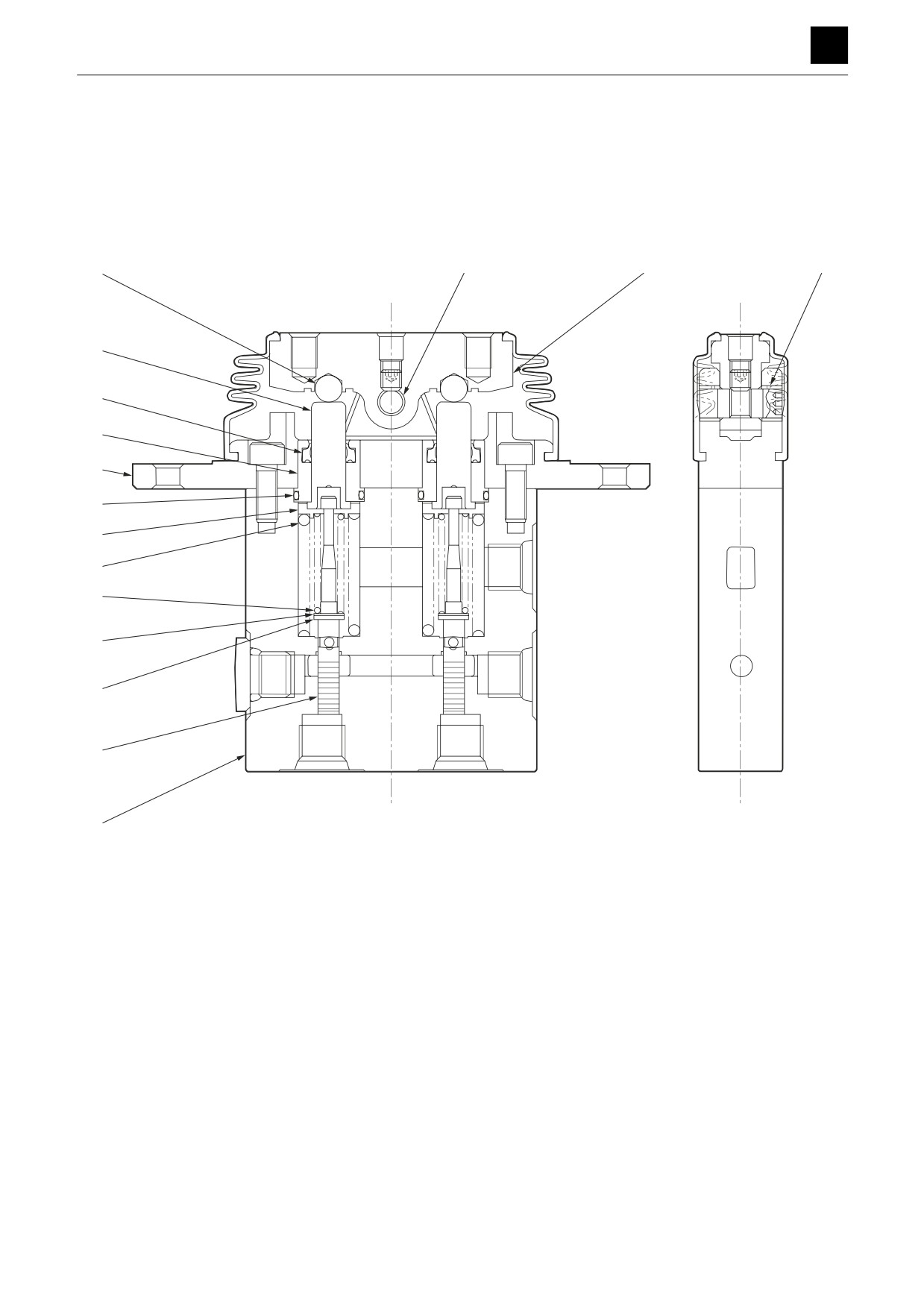
Construction
16
13
15
14
6
4
3
2
5
9
12
11
7
10
8
1
4K4AF01Z
1. Casing
7. Shim
13. Shaft
2. Cover
8. Spool
14. Bushing
3. Plug
9. Spring seat
15. Cam
4. Seal
10. Washer
16. Ball
5. O-ring
11. Spring
6. Push rod
12. Spring
1
PILOT VALVE (SWING, BLADE)
4K3AQ00
DISASSEMBLY AND ASSEMBLY
4
PILOT VALVE (SWING, BLADE)
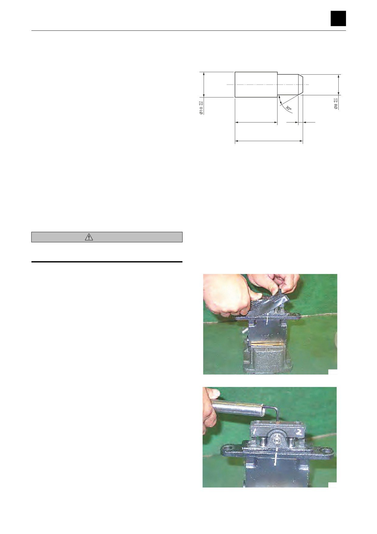
Special Jigs
(for bushing removal)
Disassembly and Assembly
General Precautions
• Perform disassembly and assembly work in a clean
place. Provide clean containers to hold parts during
disassembly.
• Clean around the ports before disassembly. Remove
20
2
paint around connectors with a wire brush.
• Clean the disassembled parts with wash oil.
30
• Put alignment marks on all parts to reassemble them in
the same positions.
4K5AF02Z
• After each disassembly, replace all seals and apply a
thin layer of grease to them.
• Check each part for abnormal wear or seizing. Re-
move any burrs with sandpaper.
• Do not move adjusting screws, unless absolutely nec-
essary.
Disassembly
WARNING
The spring may fly out during disassembly. Refer to the
construction diagram and take precautions.
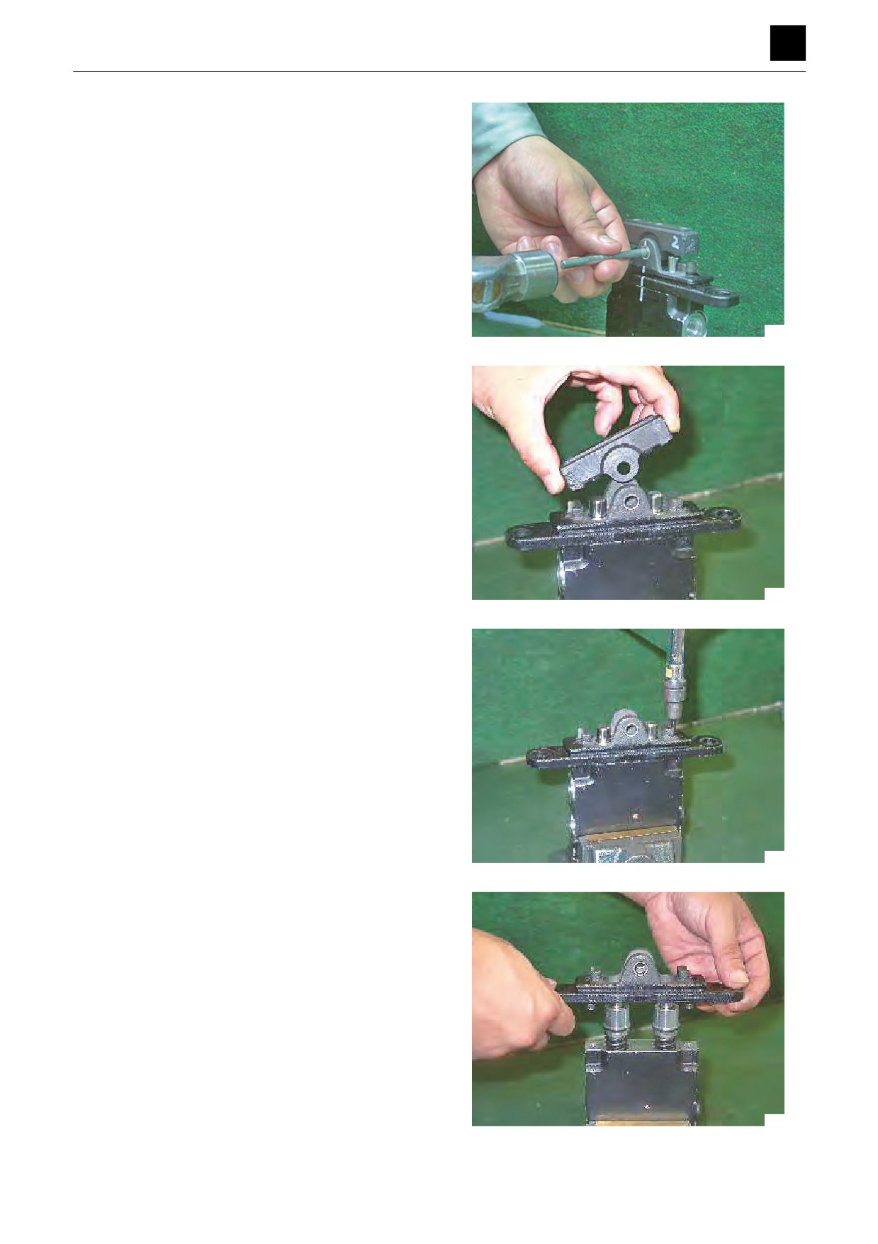
1. Insert a cushion plate between the pilot valve and the
vise, and fasten the pilot valve.
• Pull the bellows upward to remove it from the cov-
er.
4K4AF02Z
2. Remove the cap screw with an Allen key.
• Be aware that a high torque is required to loosen
this screw.
4K4AF03Z
2
PILOT VALVE (SWING, BLADE)
4K3AQ00
DISASSEMBLY AND ASSEMBLY
4
PILOT VALVE (SWING, BLADE)
3. Place a steel bar (7 mm dia. max.) against the cam
shaft and tap it lightly with a hammer.
4K4AF04Z
4. Remove the cam.
• Treat the cam and ball as an integral assembly
(that cannot be taken apart).
• Record the positional relationship between the
cam and the cover.
4K4AF05Z
5. Remove the cap screws with an Allen key.
4K4AF06Z
6. Remove the cover.
• Record the positional relationship between the
cam and the casing.
4K4AF07Z
3
PILOT VALVE (SWING, BLADE)
4K3AQ00
DISASSEMBLY AND ASSEMBLY
4
PILOT VALVE (SWING, BLADE)
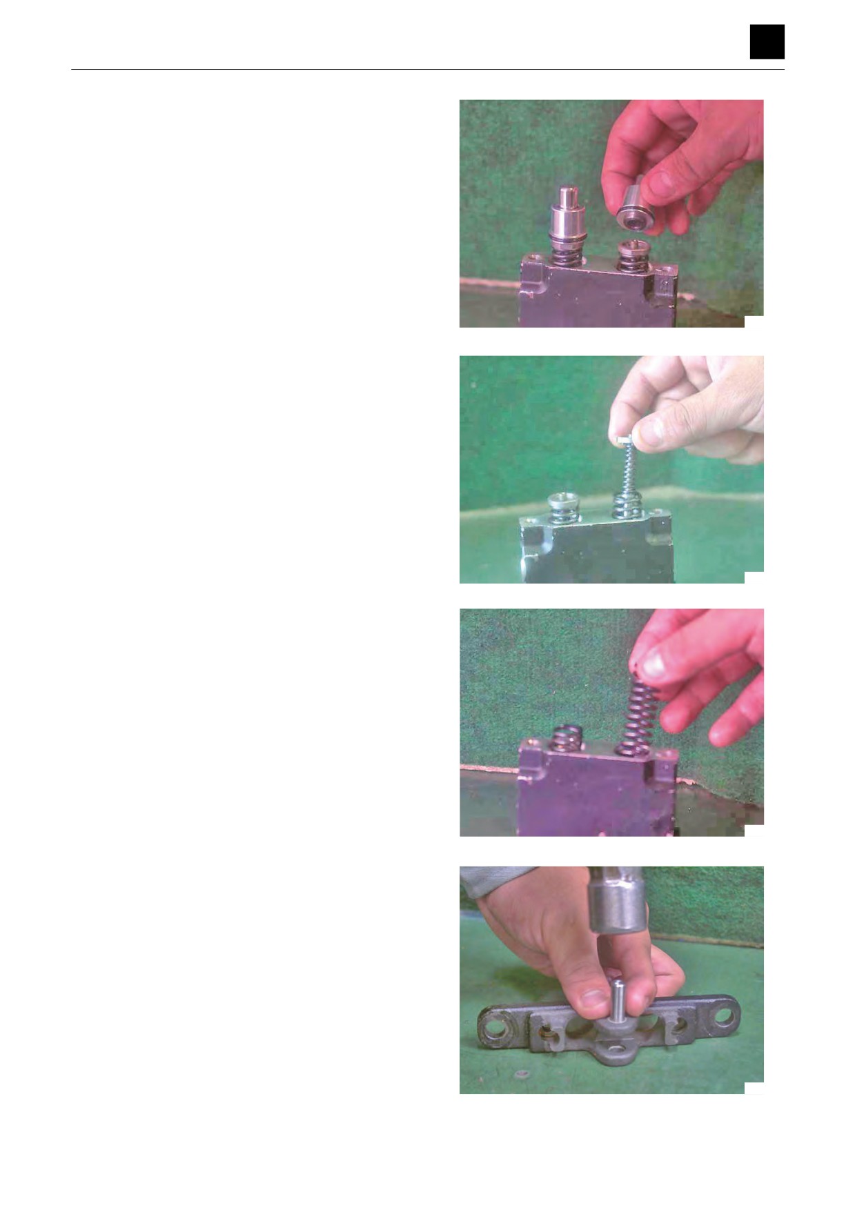
7. Remove each plugs with the push rod, packing and
O-ring.
• Record the positional relationship between the
plugs and the casing.
4K4AF08Z
8. Remove the pressure reducing valve assemblies
and the return springs from the casing.
• Record their positional relationships with the cas-
ing holes.
4K4AF09Z
4K4AF10Z
9. Lay the cover sideways on a flat surface. Place the
special jig against the bushing and tap it lightly with
a hammer to remove the bushing.
4K4AF11Z
4
PILOT VALVE (SWING, BLADE)
4K3AQ00
DISASSEMBLY AND ASSEMBLY
4
PILOT VALVE (SWING, BLADE)
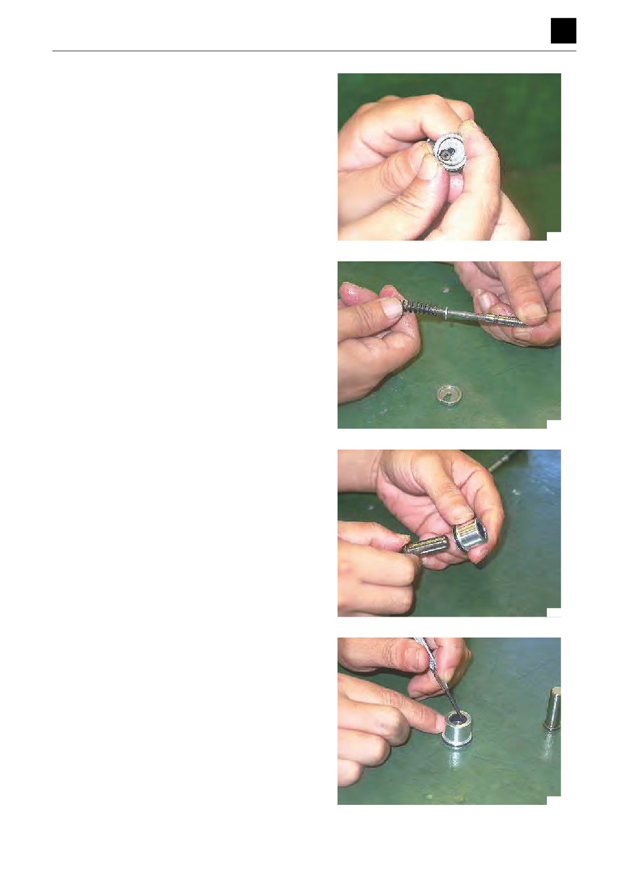
10. To disassemble the pressure reducing valve, push
down the spring seat to compress the secondary
pressure spring. At the same time, move the spring
seat sideways and pull out the spool through the
larger hole.
• Take care not to scratch the spool surface.
• Do not push down the spring seat more than 4
mm.
• During re-assembly, assemble the parts above as
a set.
4K4AF12Z
11. Separate the spool, secondary pressure spring,
shim and washer.
• During re-assembly, assemble the parts above as
a set.
• The washer adjusts the preset value of the sec-
ondary pressure spring. The washer thickness
differs for each spool assembly. In some cases
this washer is omitted.
4K4AF13Z
12. Remove the push rod from the plug.
4K4AF14Z
13. Remove the packing from the plug.
• Use a small flat head screwdriver to remove the
packing.
• Take care not to scratch the inner surface of the
plug.
4K4AF15Z
5
PILOT VALVE (SWING, BLADE)
4K3AQ00
DISASSEMBLY AND ASSEMBLY
4
PILOT VALVE (SWING, BLADE)
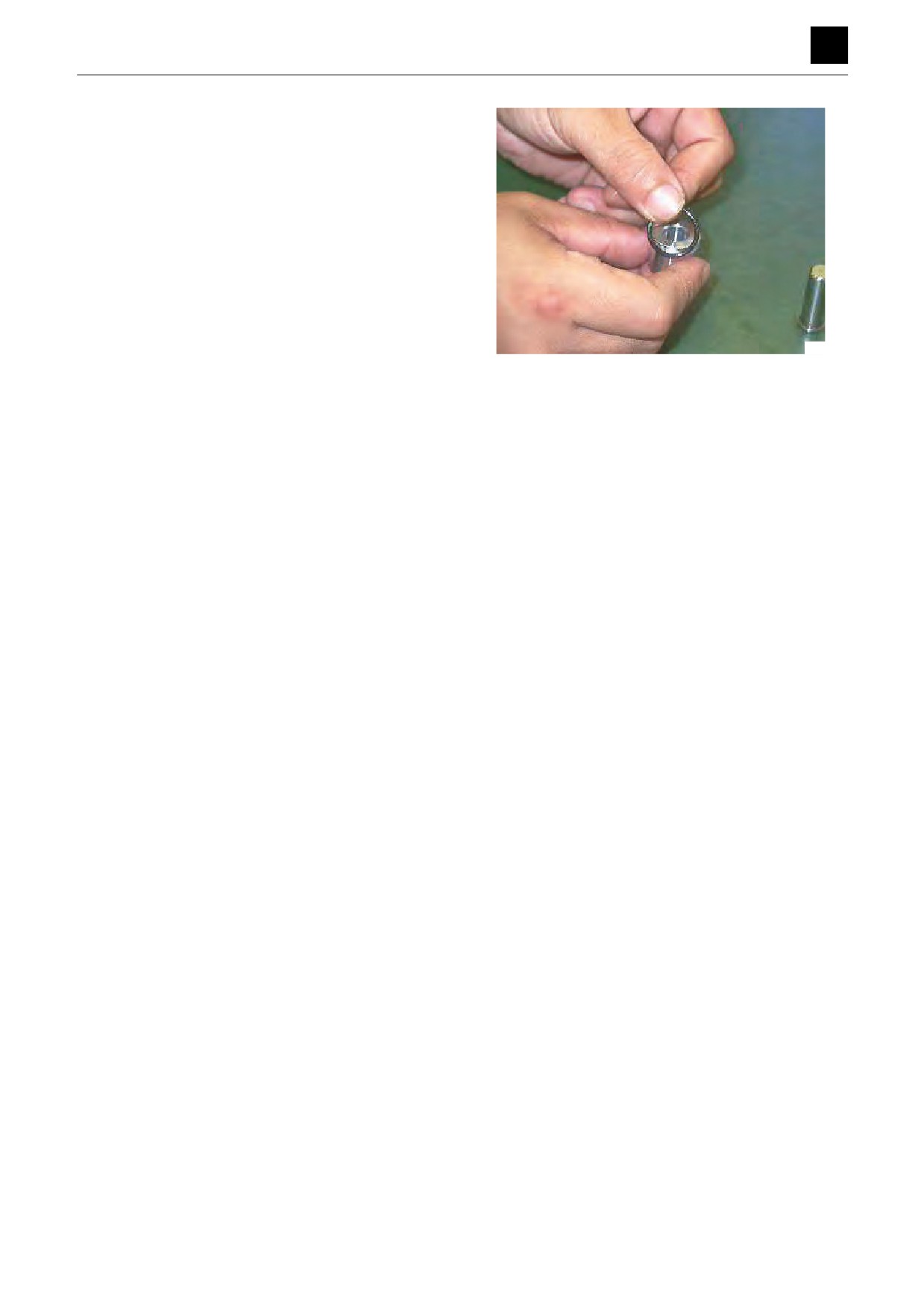
14. Remove the O-ring from the plug.
4K4AF16Z
6
PILOT VALVE (SWING, BLADE)
4K3AQ00
DISASSEMBLY AND ASSEMBLY
4
PILOT VALVE (SWING, BLADE)
Assembly
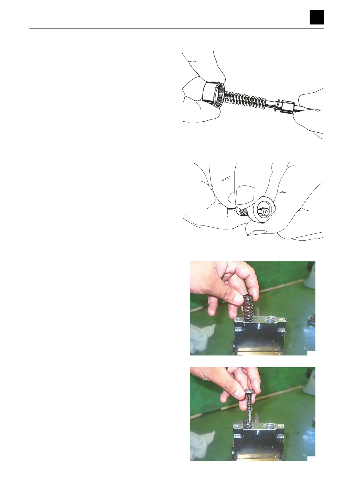
1. In sequence, install the washer, shim, secondary
pressure spring and spring seat onto the spool.
• The washer adjusts the preset value of the sec-
ondary pressure spring. The washer thickness
differs for each spool assembly. In some cases
this washer is omitted.
4K4AF17Z
2. Insert the spool through the larger hole of the spring
seat. Push down the spring seat to compress the
secondary pressure spring and move the spring seat
sideways to install it.
• Take care not to scratch the spool surface.
• Do not push down the spring seat more than 4
mm.
4K4AF18Z
3. Fasten the casing in a vice.
• Install the return springs in the casing.
• Install them in the positions they were in before
disassembly.
4K4AF19Z
4. Install the pressure reducing valve sub-assemblies
in the casing.
• Install them in the positions they were in before
disassembly.
• When installing the pressure reducing valve sub-
assemblies, do not allow the lower end of the
spools to hit hard against the corners of the cas-
ing.
4K4AF20Z
7
PILOT VALVE (SWING, BLADE)
4K3AQ00
DISASSEMBLY AND ASSEMBLY
4
PILOT VALVE (SWING, BLADE)
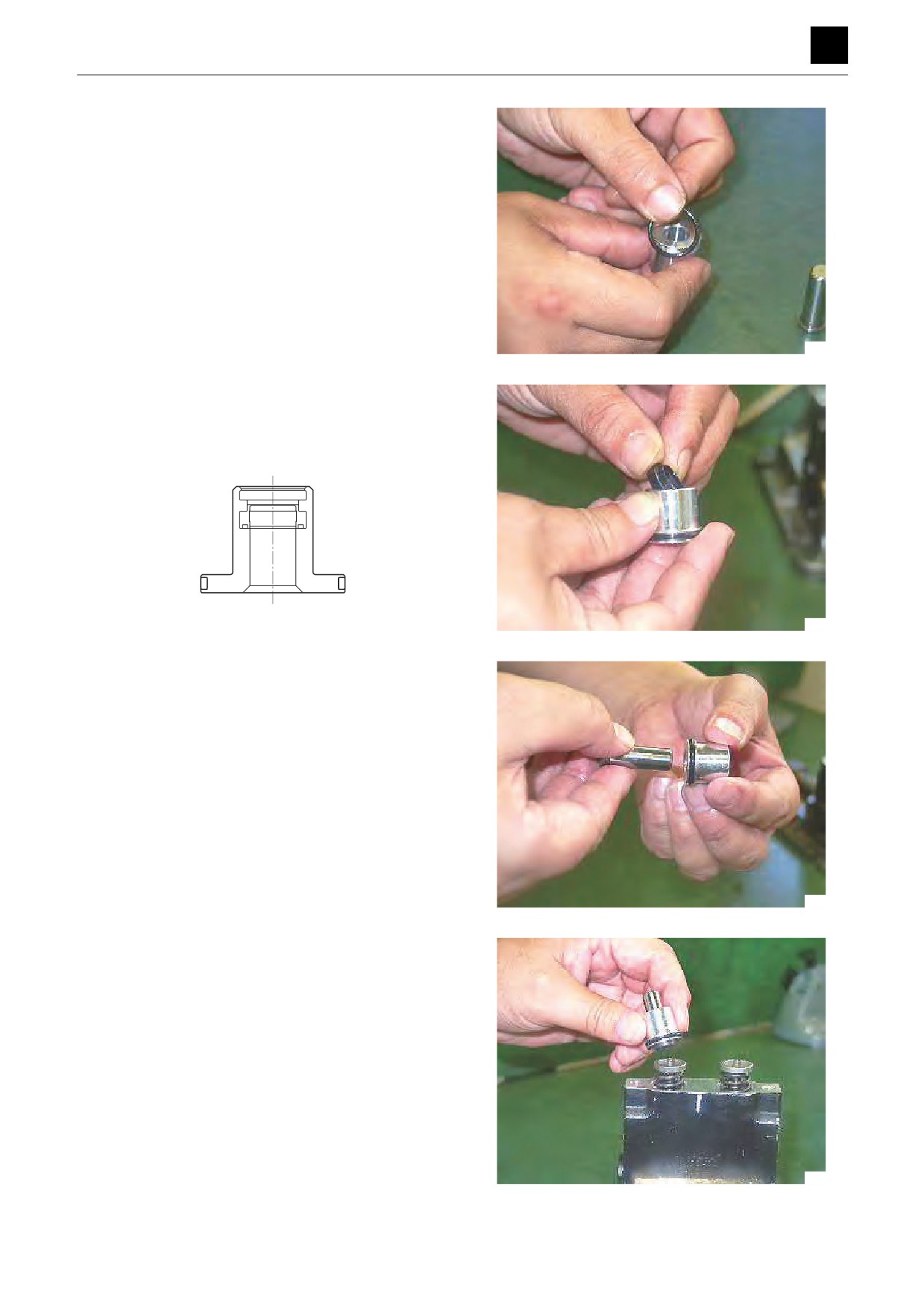
5. Attach the O-ring to the plug.
4K4AF21Z
6. Insert the packing in the plug.
• Insert the packing in the correct orientation.
• Apply a thin layer of grease to the packing before
inserting it.
4K5AF36Z
4K4AF22Z
7. Insert the push rod into the plug.
• Apply hydraulic oil to the push rod before installa-
tion.
• Do not force in the push rod hard enough to dam-
age the packing lip.
4K4AF23Z
8. Install the push rod sub-assemblies assembled at
step 7 above into the casing.
4K4AF24Z
8
PILOT VALVE (SWING, BLADE)
4K3AQ00
DISASSEMBLY AND ASSEMBLY
4
PILOT VALVE (SWING, BLADE)
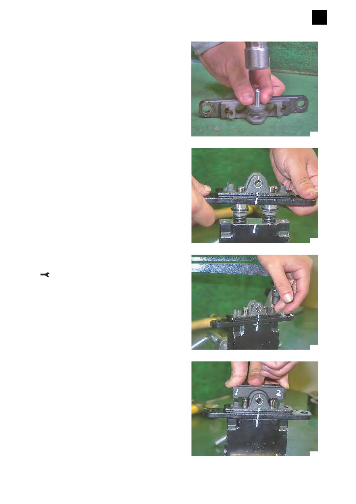
9. Lay the cover sideways on a flat surface. Place the
special jig against the bushing and tap it lightly with
a hammer to press-fit the bushing into the cover.
• Ensure that the end of the bushing does not pro-
trude into the inside of the cover.
4K4AF11Z
10. Attach the cover to the casing.
• Install it in the same position as before disassem-
bly.
• Make sure that the cover is not lifted by the return
springs.
4K4AF25Z
11. Tighten the cap screws to the specified torque.
• Ensure that the cover is level.
Cap screw: 8.8 ± 0.1 N·m
4K4AF26Z
12. Attach the cam to the cover.
• Install it in the same position as before disassem-
bly.
4K4AF27Z
9
PILOT VALVE (SWING, BLADE)
4K3AQ00
DISASSEMBLY AND ASSEMBLY
4
PILOT VALVE (SWING, BLADE)
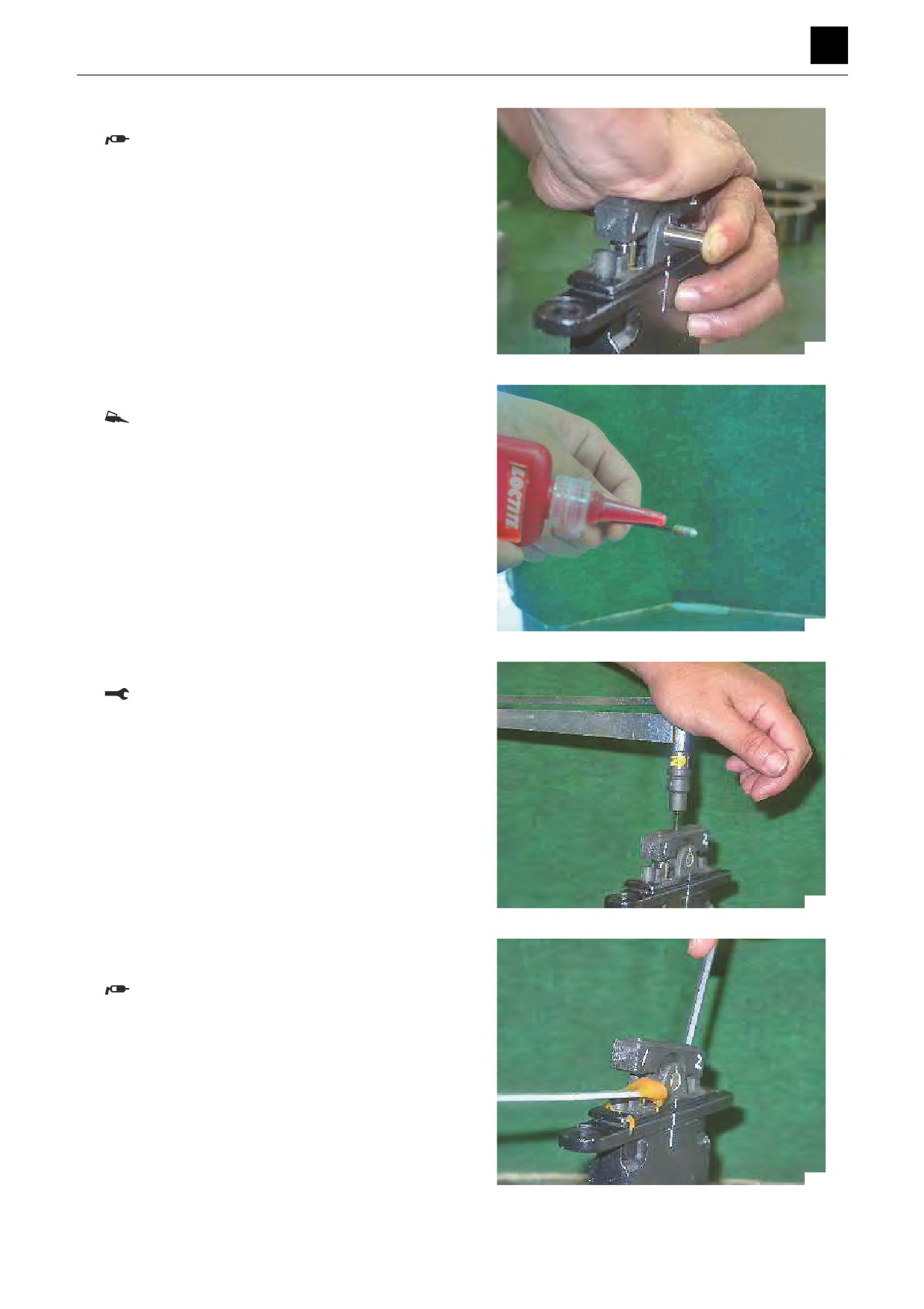
13. Insert the cam shaft while holding down the cam.
Apply grease to the sliding surfaces of the cam
shaft bearing.
4K4AF28Z
14. Apply Loctite to the cap screw.
Cap screw: Loctite #241, or equivalent.
4K4AF29Z
15. Tighten the cap screw to the specified torque.
Cap screw: 6.9 ± 1.0 N·m
4K4AF30Z
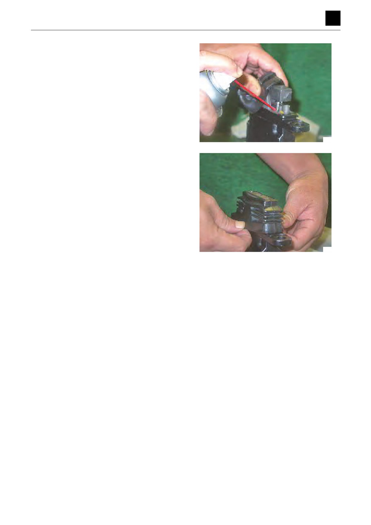
16. Tilt the cam and apply grease to the top of the push
rods.
Apply the grease with a soft spatula to avoid
scratching the surfaces of the push rods or
plugs.
4K4AF31Z
10
PILOT VALVE (SWING, BLADE)
4K3AQ00
DISASSEMBLY AND ASSEMBLY
4
PILOT VALVE (SWING, BLADE)
17. Engage the top of the bellows with the cam, and in-
sert the bottom of the bellows into the groove in the
cover.
• Before inserting the bottom of the bellows into the
groove in the cover, spray the inside of the bel-
lows with rust-inhibiting oil.
• Be sure to attach the bellows correctly. The dust-
proof and waterproof properties will be compro-
mised if the bellows is not firmly inserted into the
groove or is twisted in the groove.
4K4AF32Z
4K4AF33Z
11
PILOT VALVE (SWING, BLADE)
4K3AQ00
DISASSEMBLY AND ASSEMBLY
4
PILOT VALVE (SWING, BLADE)
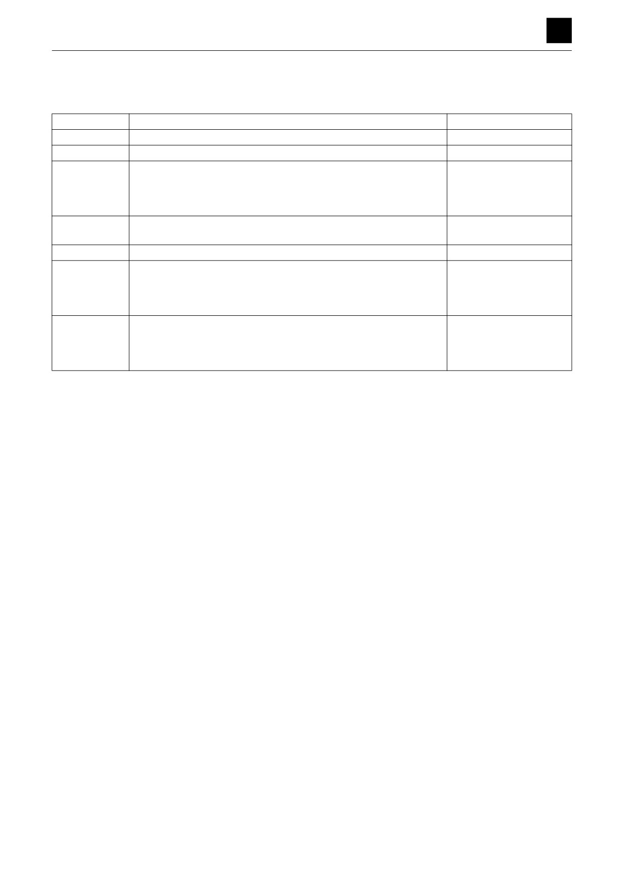
Inspection and adjustment
Checking the parts
Part
Criteria
Action
O-ring
—
• Replace
Seal
—
• Replace
Spool
• Wear on the sliding surfaces is 10 μm or more than the non-sliding
• Replace
surfaces.
• Scratches on the sliding surfaces
• Replace
• Spool does not move smoothly.
• Replace
Push rod
• Tip is worn 1 mm or more
• Replace
• Scratches on the sliding surfaces
• Replace
Plug
• Imperfect sealing due to damage
• Repair or replace
Controls
• Looseness in the pin, shaft or joint of the controls results in 2 mm
• Tighten to the specified
play, or more.
torque
• Wear of the pin, shaft or joint of the controls results in 2 mm play, or
• Replace
more.
Casing, port
• Scratches, rust, or corrosion at the parts in sliding contact with the
• Replace
plate
spool.
• Scratches, rust, or corrosion of the seal area in contact with the O-
• Repair or replace
ring
12
PILOT VALVE (SWING, BLADE)
4K3AQ00
DISASSEMBLY AND ASSEMBLY
4
PILOT VALVE (TRAVEL)
PILOT VALVE (TRAVEL)
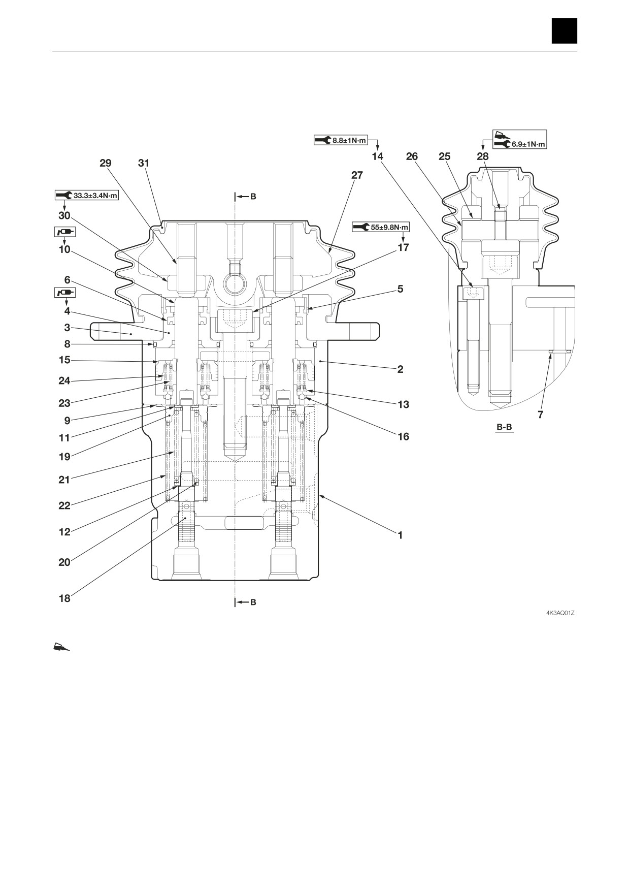
Construction
Loctite #241
1. Casing
9. O-ring
17. Cap screw
25. Bushing
2. Casing
10. Push rod
18. Spool
26. Shaft
3. Cover
11. Washer 1
19. Spring seat
27. Cam
4. Plug
12. Washer 2
20. Washer 3
28. Cap screw
5. Grease cup
13. Spring seat
21. Spring
29. Screw
6. Seal
14. Cap screw
22. Spring
30. Nut
7. O-ring
15. Piston
23. Spring
31. Boot
8. O-ring
16. Ball
24. Spring
1
PILOT VALVE (TRAVEL)
4K3AQ01
DISASSEMBLY AND ASSEMBLY
4
PILOT VALVE (TRAVEL)
Disassembly and Assembly
The numbers in parentheses () listed after the names of
parts in this document match the numbers used in the
construction diagrams and parts lists.
General Precautions
• Perform disassembly and assembly work in a clean
place. Provide clean containers to hold parts during
disassembly.
• Clean around the ports before disassembly. Remove
paint around connectors with a wire brush.
• Clean the disassembled parts with wash oil.
• Put alignment marks on all parts to reassemble them in
the same positions.
• After each disassembly, replace all seals and apply a
thin layer of grease to them.
• Check each part for abnormal wear or seizing. Re-
move any burrs with sandpaper.
• Do not move adjusting screws, unless absolutely nec-
essary.
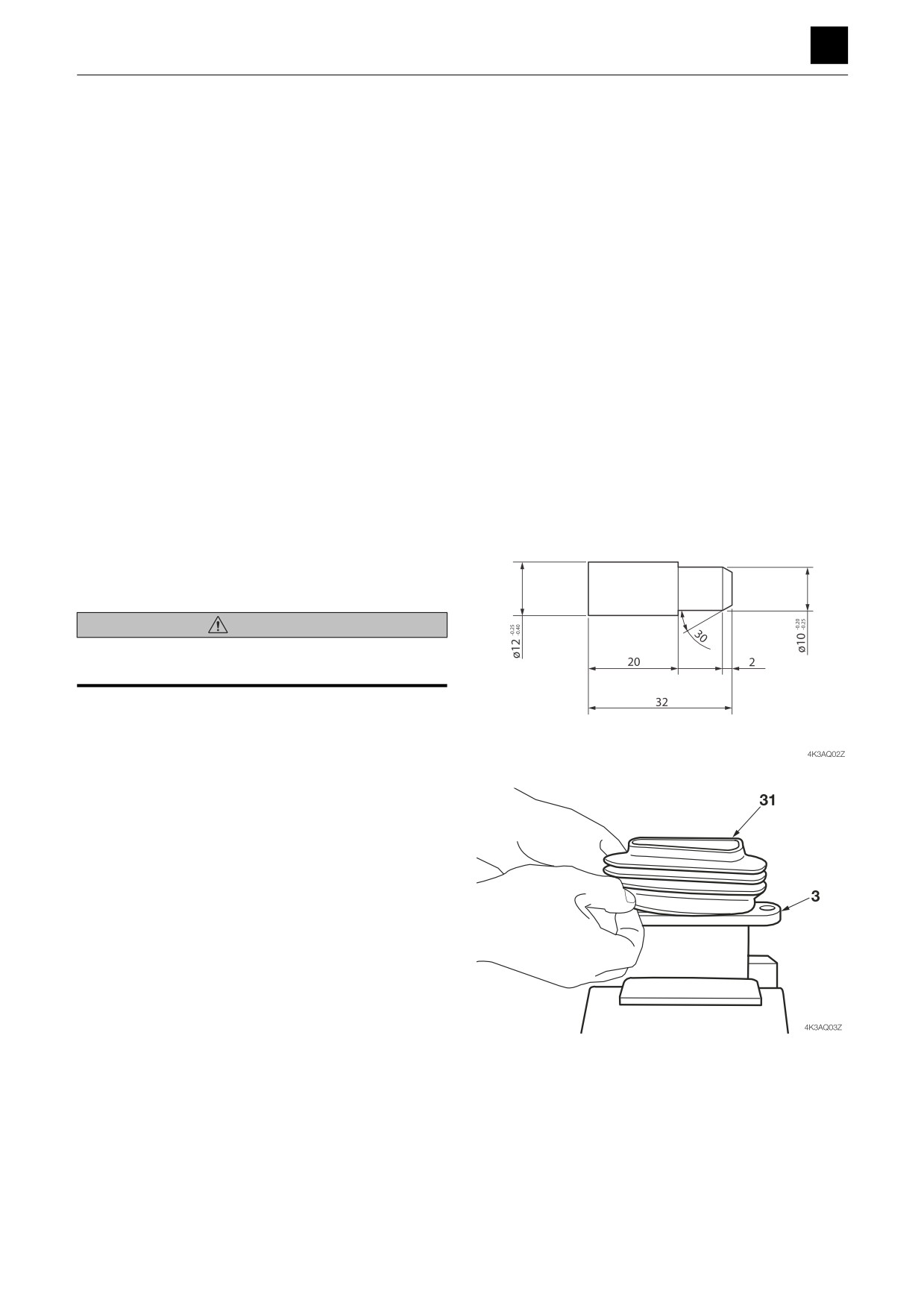
Special Jigs
(for bushing removal)
Disassembly
WARNING
The spring may fly out during disassembly. Refer to the
construction diagram and take precautions.
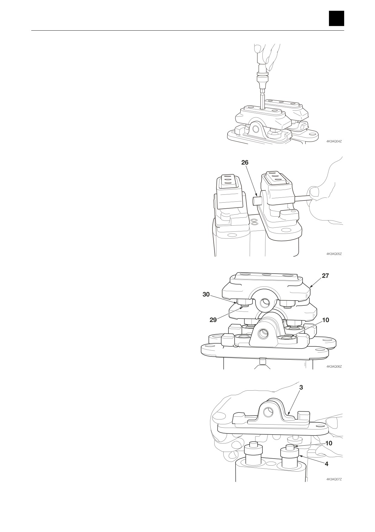
1. Remove the boot (31) from the cover (3).
2
PILOT VALVE (TRAVEL)
4K3AQ01
DISASSEMBLY AND ASSEMBLY
4
PILOT VALVE (TRAVEL)
2. Loosen the cap screws (28).
3. Remove the shaft (26).
• Use a rod (8 mm dia. max.) and tap it with a ham-
mer.
4. Remove the cam (27) with the screws (29) and nuts
(30) attached.
• Take care to prevent the push rod (10) flying out.
• Neutral adjustment is required for the screws (29)
and nuts (30). Do not remove them, unless abso-
lutely necessary.
5. Remove the cap screws (17) and remove the cover
(3).
3
PILOT VALVE (TRAVEL)
4K3AQ01
DISASSEMBLY AND ASSEMBLY
4
PILOT VALVE (TRAVEL)
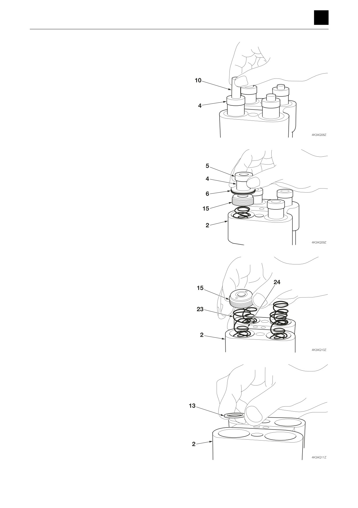
6. Remove the push rod (10) from the plug (4).
• Take care not to scratch the push rod (10) surfac-
es.
7. Remove the plug (4) from the casing (2), with the
grease cup (5) and seal (6) attached.
8. Remove the piston (15) and the springs (23) (24)
from the casing (2).
9. Remove the spring seat (13) from the casing (2).
4
PILOT VALVE (TRAVEL)
4K3AQ01
DISASSEMBLY AND ASSEMBLY
4
PILOT VALVE (TRAVEL)
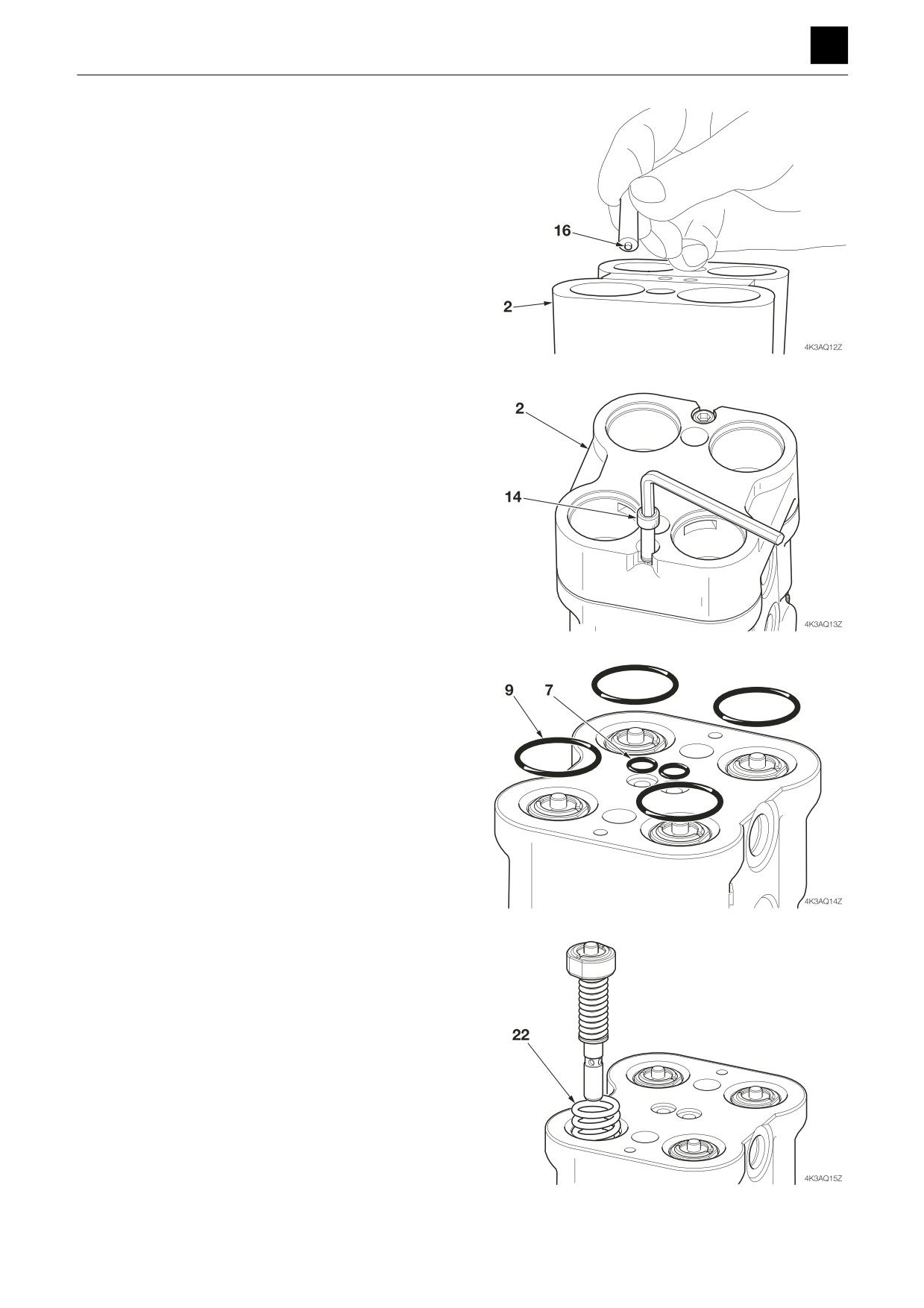
10. Remove the balls (16) from the casing (2).
• Use a magnet.
11. Remove the cap screws (14) and remove the casing
(2).
12. Remove the O-rings (7) (9) from the casing (1).
13. Remove the pressure reducing valves and springs
(22).
5
PILOT VALVE (TRAVEL)
4K3AQ01
DISASSEMBLY AND ASSEMBLY
4
PILOT VALVE (TRAVEL)
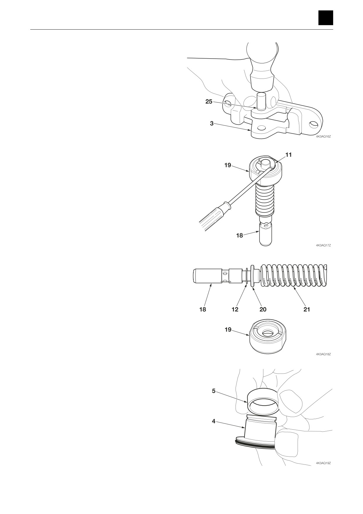
14. Remove the bushings (25) from the cover (3).
• Use the jig.
15. Disassemble the pressure reducing valve.
a. Remove washer 1 (11).
• Stand the spool (18) on a flat surface. Push down
the spring seat (19).
• Do not push down the spring seat (19) more than
4 mm.
b. Remove the spring seat (19), spring (21), washer
2 (12), and washer 3 (20) from the spool (18).
• Washer 2 is used for adjustment. In some cases
this washer is omitted.
16. Remove the grease cup (5) from the plug (4).
6
PILOT VALVE (TRAVEL)
4K3AQ01
DISASSEMBLY AND ASSEMBLY
4
PILOT VALVE (TRAVEL)
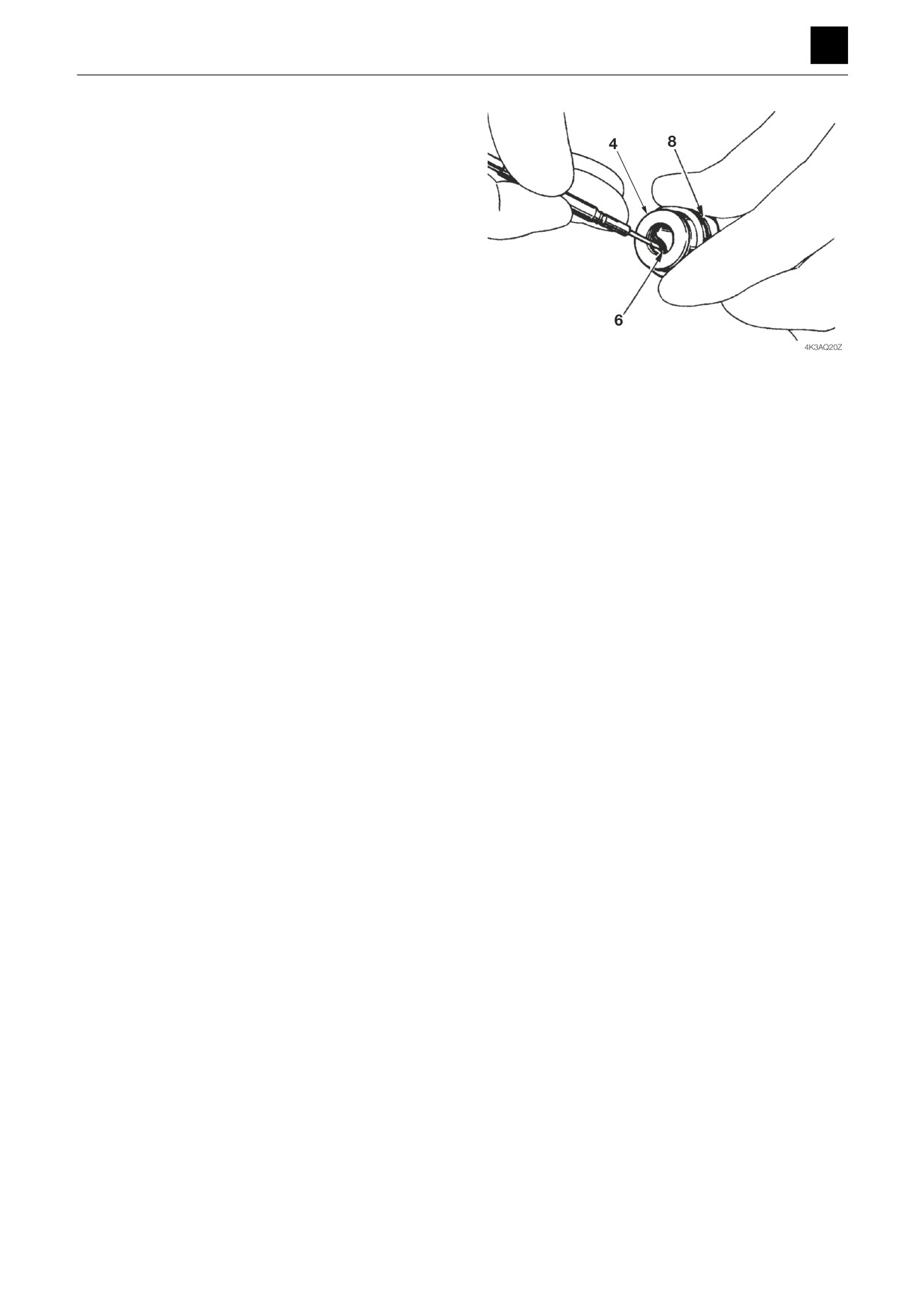
17. Remove the seal (6) and the O-ring (8) from the plug
(4).
7
PILOT VALVE (TRAVEL)
4K3AQ01
DISASSEMBLY AND ASSEMBLY
4
PILOT VALVE (TRAVEL)
Assembly
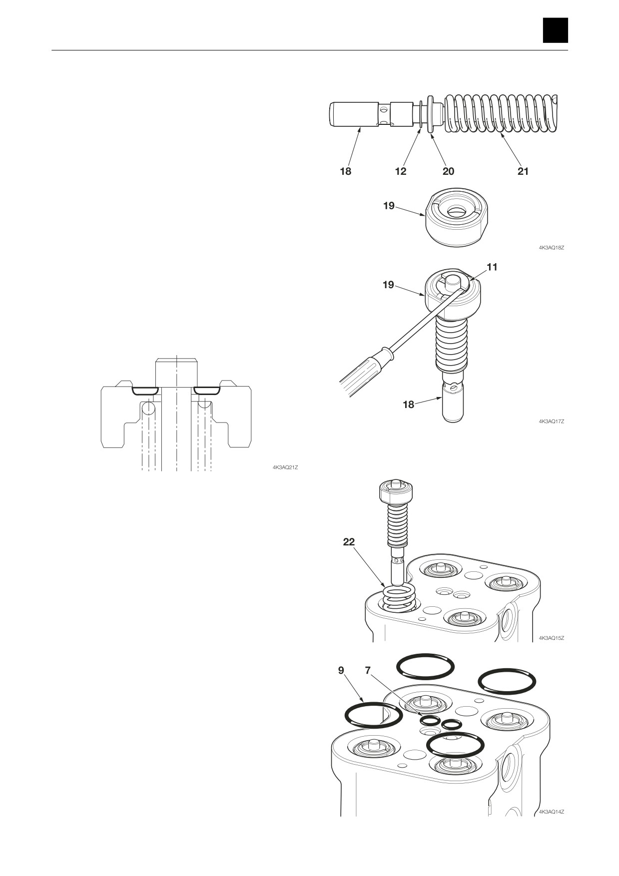
1. Assemble the pressure reducing valve.
a. Install washer 2 (12), washer 3 (20), spring (21),
and the spring seat (19) onto the spool (18).
b. Attach washer 1 (11) to the spool (18).
• Stand the spool (18) on a flat surface. Push down
the spring seat (19).
• Do not push down the spring seat (19) more than
4 mm.
• Engage the sharp edge of washer 1 (11) onto the
head of the spool (18).
2. Install the springs (22) and the pressure reducing
valves in the casing.
3. Fit the O-rings (7) (9) to the casing (1).
8
PILOT VALVE (TRAVEL)
4K3AQ01
DISASSEMBLY AND ASSEMBLY
4
PILOT VALVE (TRAVEL)
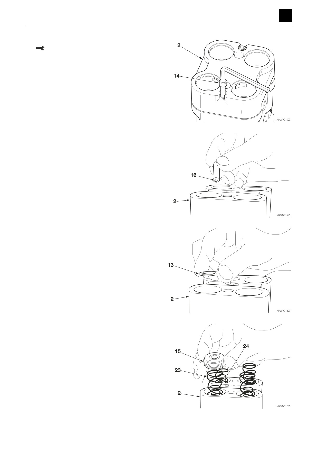
4. Use the cap screws (14) to attach the casing (2).
Cap screw: 8.8 ± 1 N·m
5. Insert the balls (16) in the casing (2).
6. Insert the spring seat (13) in the casing (2).
7. Install the piston (15) and the springs (23) (24) in the
casing (2).
9
PILOT VALVE (TRAVEL)
4K3AQ01
DISASSEMBLY AND ASSEMBLY
4
PILOT VALVE (TRAVEL)
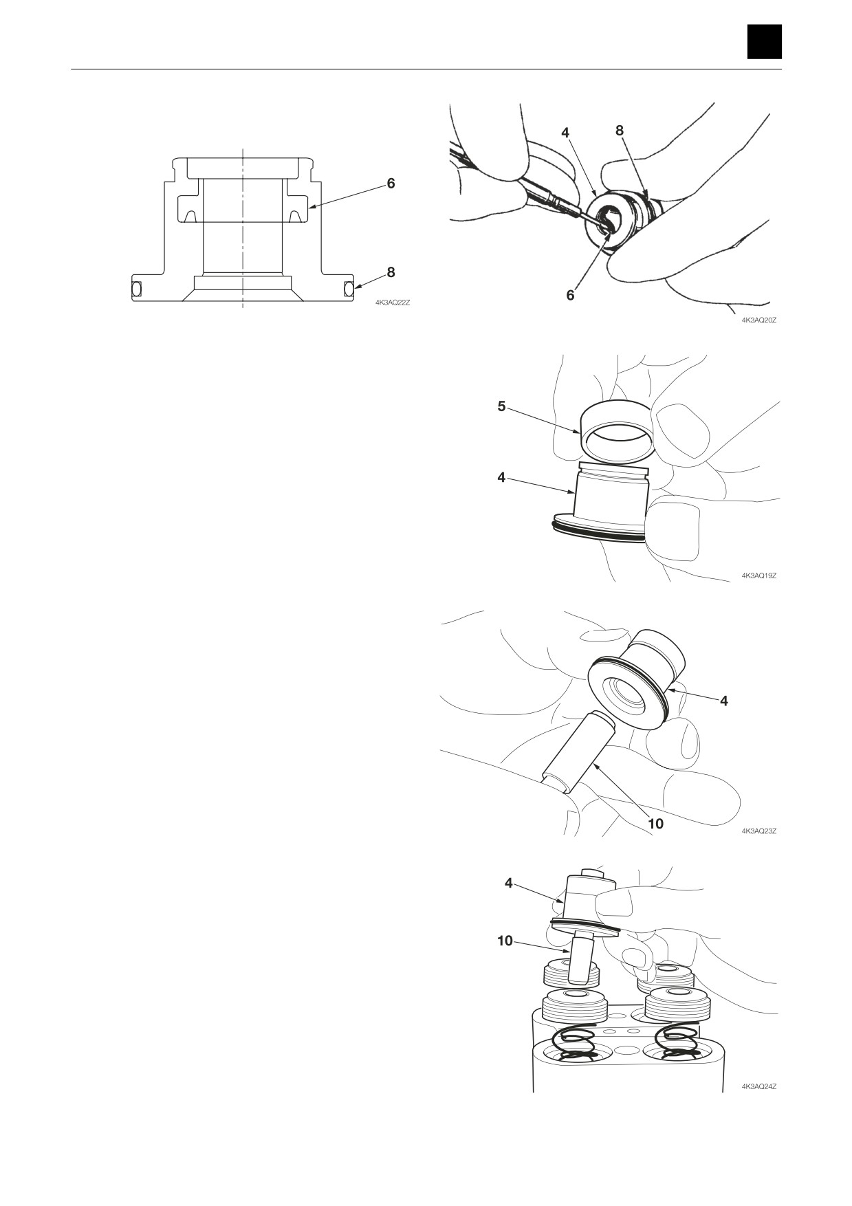
8. Attach the seal (6) and O-ring (8) to each plug (4).
• Insert the seal (6) in the correct orientation.
9. Attach the grease cup (5) to the plug (4).
10. Insert the push rod (10) into the plug (4).
• Apply hydraulic oil to the push rod (10) before in-
stallation.
11. Install the plugs (4) and push rods (10) assembled at
step 10 above into the casing.
10
PILOT VALVE (TRAVEL)
4K3AQ01
DISASSEMBLY AND ASSEMBLY
4
PILOT VALVE (TRAVEL)
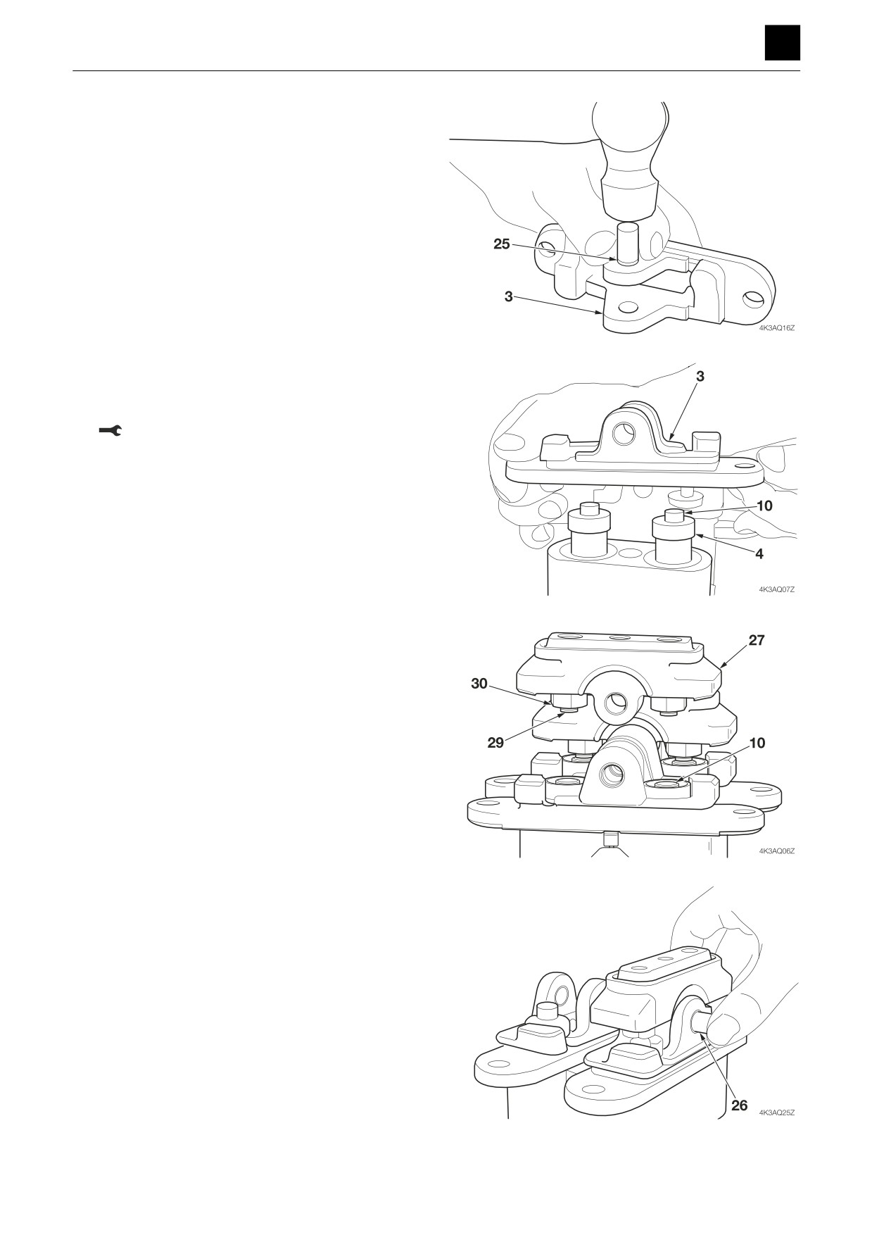
12. Install the bushings (25) in the cover (3).
• Use the jig.
13. Attach the cover (3) to the casing (2) using the cap
screws (17).
• Ensure that the cover (3) is level.
Cap screw: 55 ± 9.8 N·m
14. Attach the cam (27) to the cover (3).
• If the screw (29) and nut (30) have been removed,
reattach them temporarily.
15. Insert the shaft (26).
11
PILOT VALVE (TRAVEL)
4K3AQ01
DISASSEMBLY AND ASSEMBLY
4
PILOT VALVE (TRAVEL)
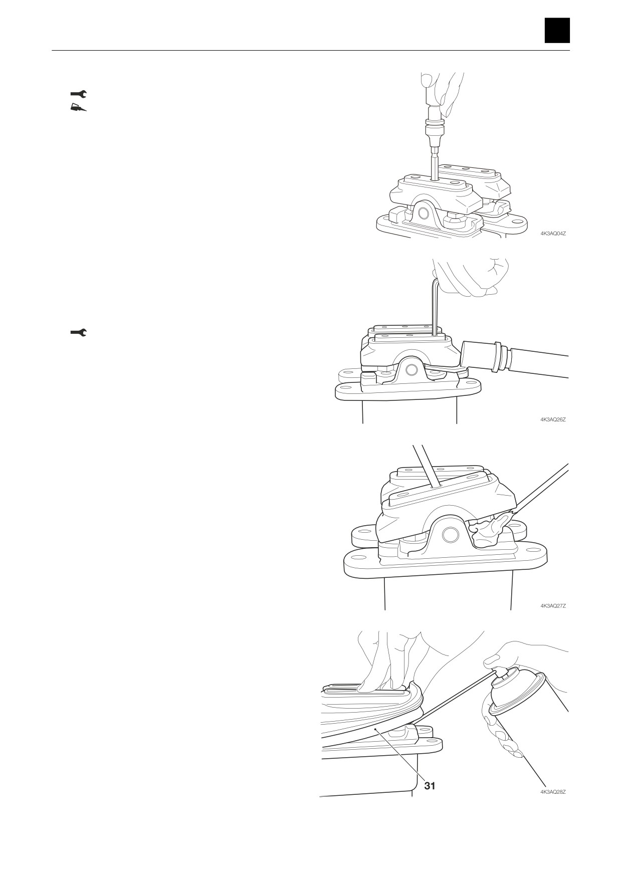
16. Attach the cap screws (28).
Cap screw: 6.9 ± 1 N·m
Loctite #241
17. Adjust the cam (27) and cover (3) level.
a. Turn the screws to adjust the cams (27) and cover
(3) level.
• Ensure that the screws are not loose.
b. Tighten to the specified torque.
Nut: 33 ± 3.4 N·m
18. Apply grease to the top of the push rods and fill the
grease cups with grease.
19. Install the boot (31).
• Spray the inside of the boot with rust-inhibiting oil.
12
PILOT VALVE (TRAVEL)
4K3AQ01
DISASSEMBLY AND ASSEMBLY
4
PILOT VALVE (TRAVEL)
Inspection and adjustment
Checking the parts
Part
Criteria
Action
O-ring
—
• Replace
Seal
—
• Replace
Spool
• Wear on the sliding surfaces is 10 μm or more than the non-sliding
• Replace
surfaces.
• Scratches on the sliding surfaces
• Replace
• Spool does not move smoothly.
• Replace
Push rod
• Tip is worn 1 mm or more
• Replace
• Scratches on the sliding surfaces
• Replace
Plug
• Imperfect sealing due to damage
• Repair or replace
Controls
• Looseness in the pin, shaft or joint of the controls results in 2 mm
• Tighten to the specified
play, or more.
torque
• Wear of the pin, shaft or joint of the controls results in 2 mm play, or
• Replace
more.
Casing, port
• Scratches, rust, or corrosion at the parts in sliding contact with the
• Replace
plate
spool.
• Scratches, rust, or corrosion of the seal part in contact with the O-ring
• Repair or replace
13
PILOT VALVE (TRAVEL)
4K3AQ01
DISASSEMBLY AND ASSEMBLY
4
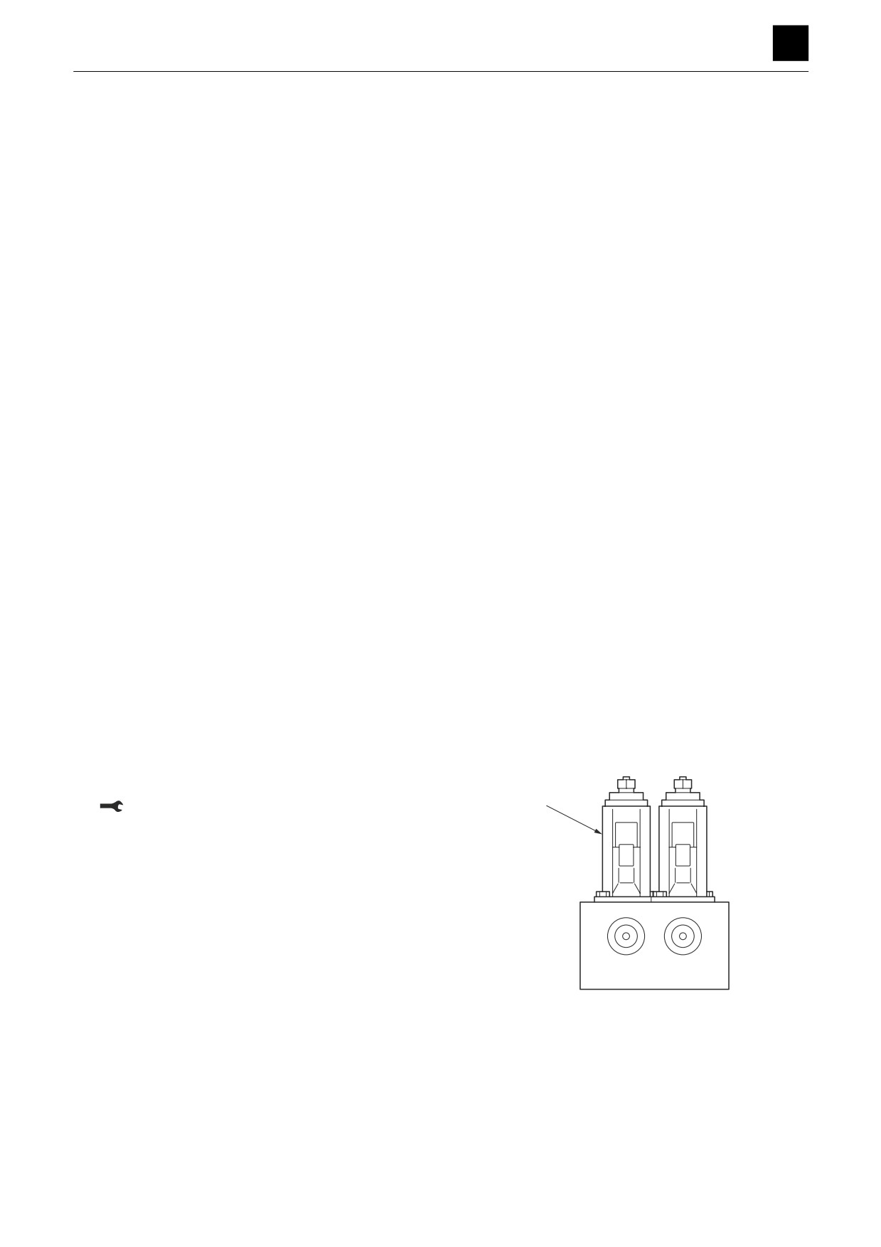
PROPORTIONAL CONTROL SOLENOID VALVE
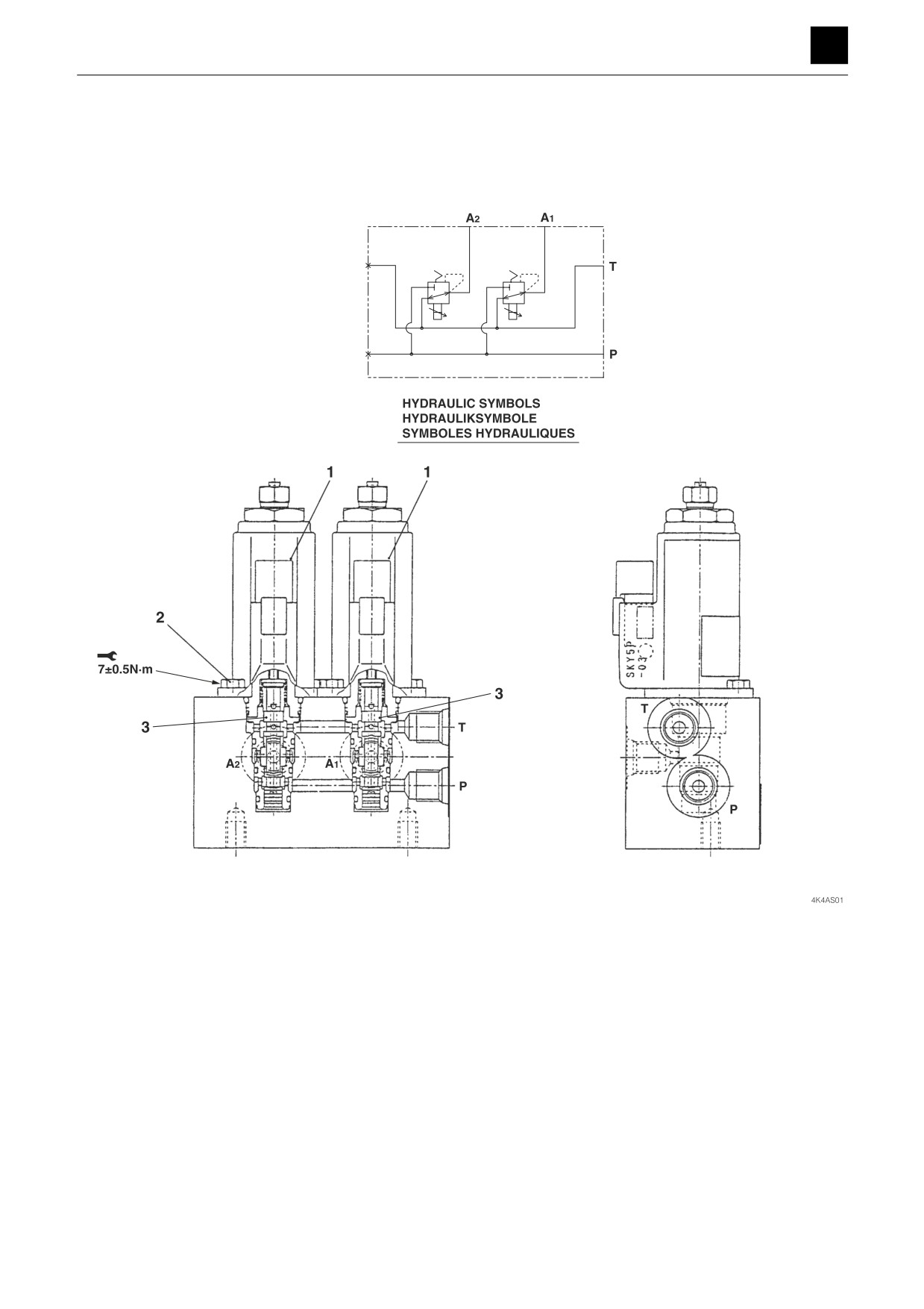
PROPORTIONAL CONTROL SOLENOID VALVE
Construction
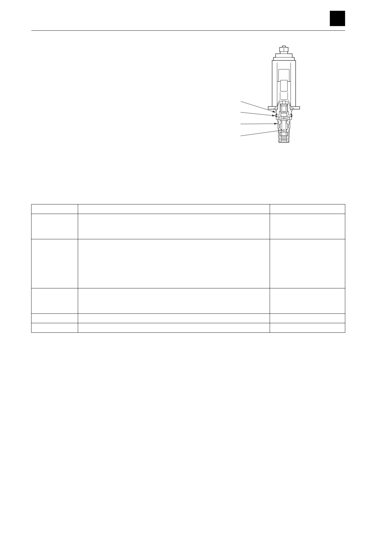
1. Proportional control solenoid
2. Bolt
3. Spool
1
PROPORTIONAL CONTROL SOLENOID VALVE
4K4AS00
DISASSEMBLY AND ASSEMBLY
4
PROPORTIONAL CONTROL SOLENOID VALVE
Disassembly and assembly
The numbers in parentheses, ( ), listed after the names of
parts throughout this document do not necessarily match
the numbers of the same parts listed in the construction
diagrams and parts lists. The numbers listed are for part
numbers used in illustrations.
General precautions
•
Perform disassembly and assembly work in a clean
place. Provide clean containers to hold parts during
disassembly.
•
Clean around the ports before disassembly. Remove
paint around connectors with a wire brush.
•
Clean the disassembled parts with wash oil.
•
Put alignment marks on all parts to ensure that they are
reassembled in the same positions.
•
After each disassembly, replace all seals and apply a
thin layer of grease to each.
•
Check each part for abnormal wear or seizing. Re-
move any burrs with sandpaper.
•
Remove adhesive from screw holes that use adhesive
through the tap. Do not reuse mounting bolts or
screws.
•
Do not use cloth gloves during assembly. Fibers from
the gloves could fall off and clog valves, etc., which
could cause parts to become faulty.
•
During assembly, be sure to apply clean hydraulic oil
to all moving parts in and sliding parts that come into
contact with the hydraulic motor and valve parts be-
fore installing or attaching the part.
•
Plug all ports once assembly has been completed in
order to prevent dust and dirt from entering.
•
Do not attempt to adjust the adjusting screws at times
other than when necessary.
Disassembly
1. Take out the bolts, and remove the proportional con-
trol solenoid valve (1).
Bolt: 7 N·m ± 0.5 N·m
1
T9H204
2
PROPORTIONAL CONTROL SOLENOID VALVE
4K4AS00
DISASSEMBLY AND ASSEMBLY
4
PROPORTIONAL CONTROL SOLENOID VALVE
2. Remove the O-ring from the proportional control so-
lenoid valve (1).
• Do not attempt to remove the sleeve (2) that is
united to the solenoid (4) by the retaining ring (3)
as the parts are swaged together.
• Make sure that the spool (5) moves back and forth
a little if pushed from the sleeve (2) end.
4
3
Assembly
For assembly, refer to the construction diagram and re-
2
verse the disassembly procedure.
5
T9H205
Inspection and adjustments
Inspection
Part
Criteria
Action
Coil
• If the solenoid is burned out, shorted out, or suffering from wiring dis-
• Replace
connects
• If the wiring is shorted out or broken
• Replace
Body
• If there are scratches, rust, or corrosion present on the parts that
• Replace
make sliding contact with the spool
• If there are scratches, rust, or corrosion on the seal part in contact
• Replace
with the O-ring
• If there is other damage present that could possibly impair normal
• Replace
operation of the machine
• If there are scratches on the outer circumference that could easily
• Replace
Spool
get caught on by a fingernail
• If the spool does not move smoothly enough
• Repair or replace
Spring
• If there is rust, corrosion, deformation, or breakage present
• Replace
O-rings
—
• Replace
3
PROPORTIONAL CONTROL SOLENOID VALVE
4K4AS00
DISASSEMBLY AND ASSEMBLY
4
SOLENOID VALVE (DUAL-SECTION)
SOLENOID VALVE (DUAL-SECTION)
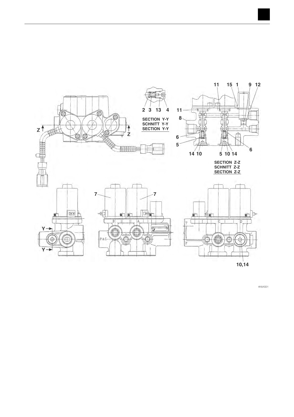
Construction
1. Cover
9. Plug
2. Plunger
10. Plug
3. Spring
11. O-ring
4. Plug
12. O-ring
5. Spring
13. O-ring
6. Spool
14. O-ring
7. Solenoid
15. O-ring
8. Body
1
SOLENOID VALVE (DUAL-SECTION)
4K6AS00
DISASSEMBLY AND ASSEMBLY
4
SOLENOID VALVE (DUAL-SECTION)
Disassembly and assembly
The numbers in parentheses, ( ), listed after the names of
parts throughout this document do not necessarily match
the numbers of the same parts listed in the construction
diagrams and parts lists. The numbers listed are for part
numbers used in illustrations.
General precautions
•
Perform disassembly and assembly work in a clean
place. Provide clean containers to hold parts during
disassembly.
•
Clean around the ports before disassembly. Remove
paint around connectors with a wire brush.
•
Clean the disassembled parts with wash oil.
•
Put alignment marks on all parts to ensure that they are
reassembled in the same positions.
•
After each disassembly, replace all seals and apply a
thin layer of grease to each.
•
Check each part for abnormal wear or seizing. Re-
move any burrs with sandpaper.
•
Remove adhesive from screw holes that use adhesive
through the tap. Do not reuse mounting bolts or
screws.
•
Do not use cloth gloves during assembly. Fibers from
the gloves could fall off and clog valves, etc., which
could cause parts to become faulty.
•
During assembly, be sure to apply clean hydraulic oil
to all moving parts in and sliding parts that come into
contact with the hydraulic motor and valve parts be-
fore installing or attaching the part.
•
Plug all ports once assembly has been completed in
order to prevent dust and dirt from entering.
•
Do not attempt to adjust the adjusting screws at times
other than when necessary.
Disassembly
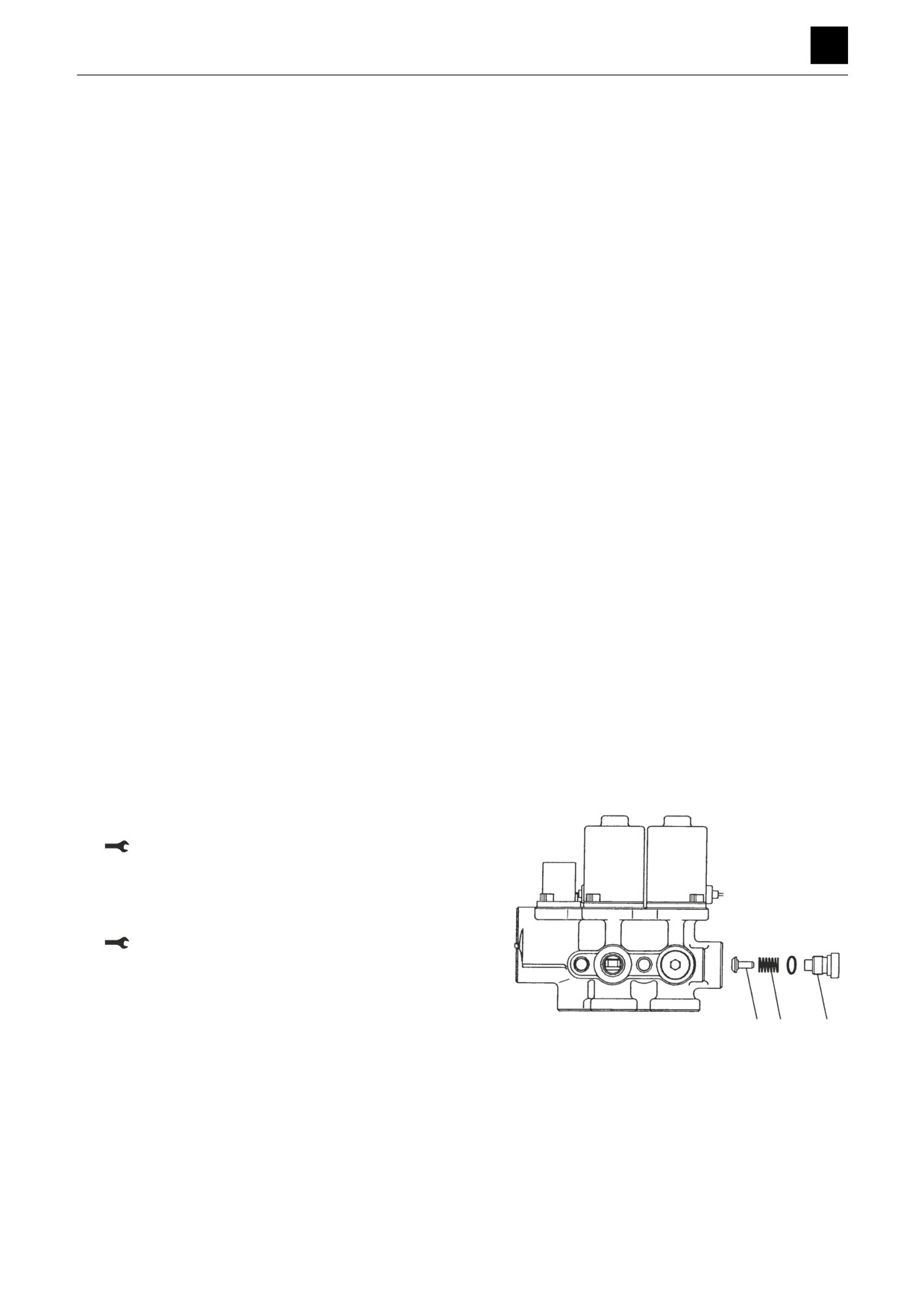
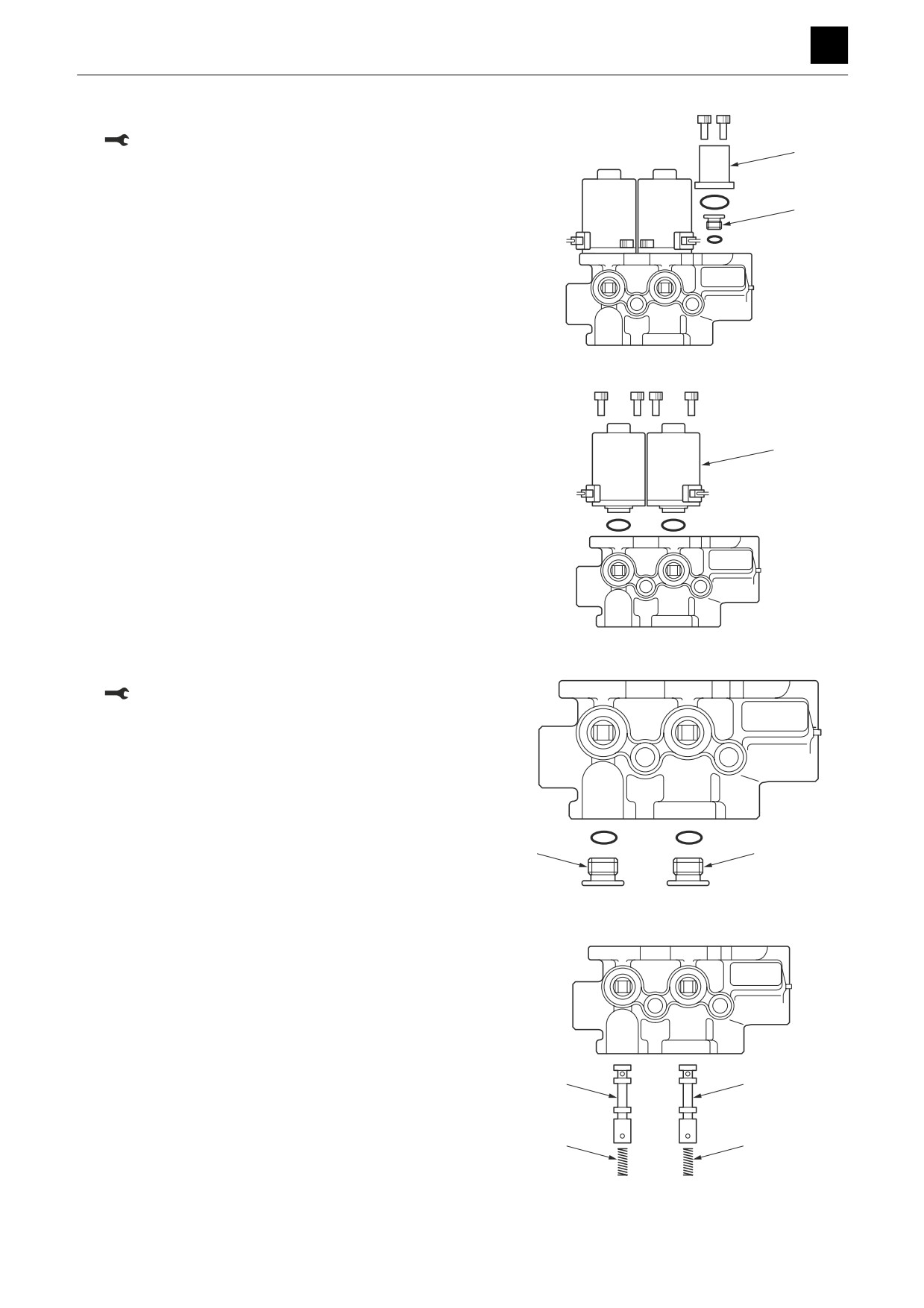
1. Take out the plug (1), and remove the spring (2) and
plunger (3).
Plug: 21.6 N·m ± 2.0 N·m
2. Remove the O-ring from the plug (1).
3. Take out the cap screws, and remove the cover (4)
and O-ring.
Cap screw: 3.9 N·m ± 1.0 N·m
3
2
1
N0H102
2
SOLENOID VALVE (DUAL-SECTION)
4K6AS00
DISASSEMBLY AND ASSEMBLY
4
SOLENOID VALVE (DUAL-SECTION)
4. Take out the plug (5), and remove the O-ring.
Plug: 9.8 N·m ± 1.0 N·m
4
5
N0H103
5. Take out the cap screws, and remove the solenoid
coil (6).
• Mark the body and coil with alignment indicators
6
to ensure that parts are put back in the proper
places during reassembly.
• Take care not to lose the push rod.
6. Remove the O-ring from the solenoid coil (6).
N0H104
7. Take out the plug (7), and remove the O-ring.
Plug: 26.5 N·m ± 2.9 N·m
7
7
N0H105
8. Remove the spool (8) and spring (9) from the body.
• Mark the spool and spring with alignment indica-
tors to ensure that parts are put back in the proper
places during reassembly.
Assembly
For assembly, refer to the construction diagram and re-
8
8
verse the disassembly procedure.
9
9
N0H106
3
SOLENOID VALVE (DUAL-SECTION)
4K6AS00
DISASSEMBLY AND ASSEMBLY
4
SOLENOID VALVE (DUAL-SECTION)
Inspection and adjustments
Inspection
Part
Criteria
Action
Coil
• If the solenoid is burned out, shorted out, or suffering from wiring dis-
• Replace
connects
• If the wiring is shorted out or broken
• Replace
Body
• If there are scratches, rust, or corrosion present on the parts that
• Replace
make sliding contact with the spool
• If there are scratches, rust, or corrosion on the seal part in contact
• Replace
with the O-ring
• If there is other damage present that could possibly impair normal
• Replace
operation of the machine
Spool
• If there are scratches on the outer circumference that could easily
• Replace
get caught on by a fingernail
• If the spool does not move smoothly enough
• Repair or replace
Spring
• If there is rust, corrosion, deformation, or breakage present
• Replace
O-rings
—
• Replace
4
SOLENOID VALVE (DUAL-SECTION)
4K6AS00
DISASSEMBLY AND ASSEMBLY
4
SHOCKLESS VALVE
SHOCKLESS VALVE
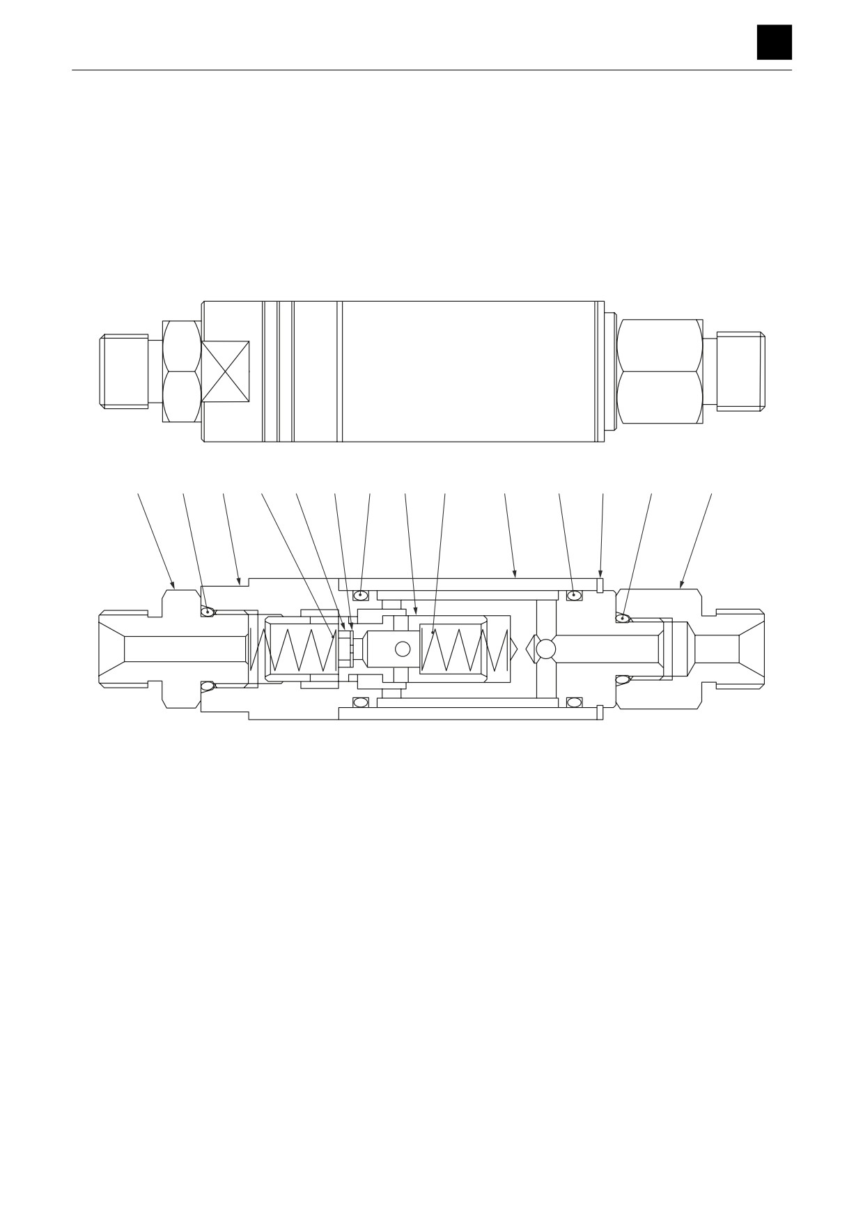
Construction
6
12
4
3
2
8
10
1
3
5
10
9
11
7
4K9AK01Z
1. Plunger
7. Connector
2. Ring
8. Orifice
3. Spring
9. Snap ring
4. Body
10. O-ring
5. Sleeve
11. O-ring
6. Connector
12. O-ring
1
SHOCKLESS VALVE
4K9AS00