Takeuchi Hydraulic excavator TB1140 (Serial No. 514400002~). Operator's Manual - page 5
DISASSEMBLY AND ASSEMBLY
UPPER FRAME 4
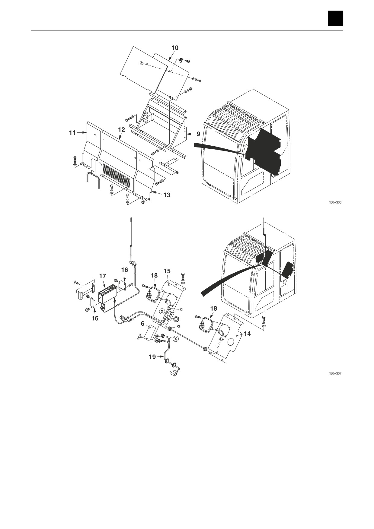
9. Box
15. Cover R
10. Cover
16. Bracket
11. Cover R
17. Radio
12. Cover C
18. Speaker
13. Cover L
19. Wire harness
14. Cover L
8
UPPER FRAME
4E0AS00
DISASSEMBLY AND ASSEMBLY
UPPER FRAME 4
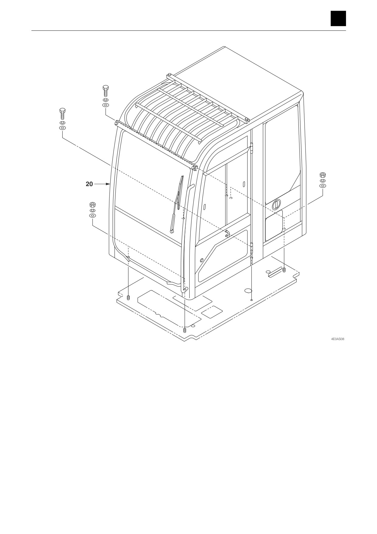
20. Cab
9
UPPER FRAME
4E0AS00
DISASSEMBLY AND ASSEMBLY
4
UPPER FRAME
Removing the cab
1. Remove the battery ground cable from the battery
terminal.
2. Remove the operator's seat from the bracket.
3. Remove the cover R (11), cover C (12), and cover L
(13).
4. Remove the cover L (14) and cover R (15).
5. Disconnect the electrical wiring and air conditioner
ducts from the cab.
6. Disconnect the window washer hose from the cab.
7. Remove the seat bracket.
8. Take out the nuts and bolts holding the cab in place,
and suspend the cab and remove it.
Cab: 370 kg (815 lb)
Installing the cab
To install, follow the same procedures as for removal but
in the reverse order.
• Suspend the cab horizontally, and secure it in place
with nuts while it is suspended.
10
UPPER FRAME
4E0AS00
DISASSEMBLY AND ASSEMBLY
4
OPERATING DEVICE
OPERATING DEVICE
Control levers
Construction
Travel, swing levers
ThreeBond #1324
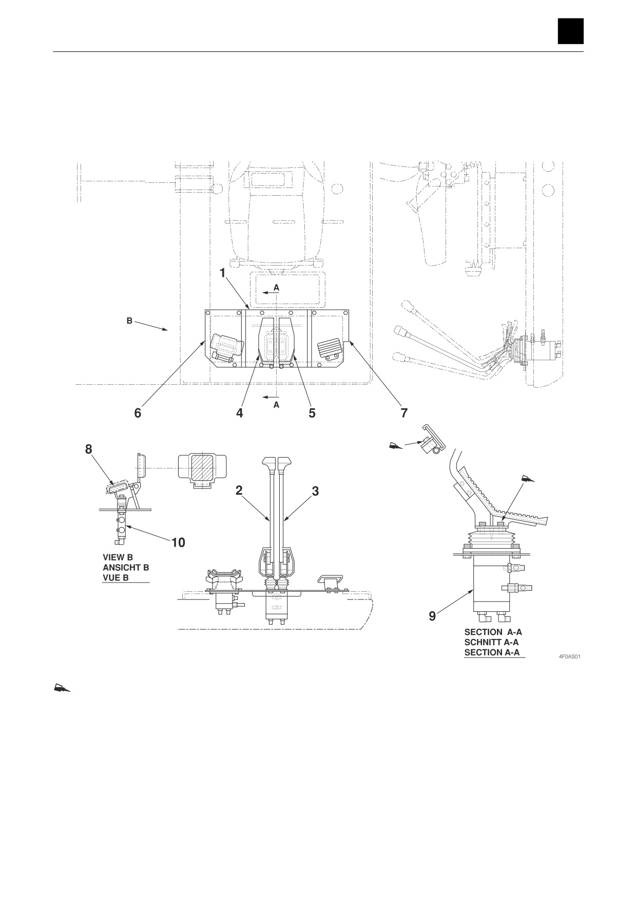
1. Bracket
6. Bracket
2. Travel lever R
7. Bracket
3. Travel lever L
8. Swing pedal
4. Travel pedal R
9. Pilot valve (Travel)
5. Travel pedal L
10. Pilot valve (Swing)
1
OPERATING DEVICE
4F0AS00
DISASSEMBLY AND ASSEMBLY
4
OPERATING DEVICE
Hydraulic pilot unit
Type A (ISO)
RP
R4
R3
R1
R2
RT
Pa7
Pa5
Pa4
Pa3
Pb5
Pb8
Pb3
Pb7
LP
L4
L3
L1
a
L2
LT
MP6
MT6
MP7
MT7
J3J1
J7J5
J2
J4
J6
J8
Pra3
Pra2
Prb3
Pa8
Pa9
Pra1
Prb2
Pa5
Pa4
Pc2
Prb1
Pc3
Pa6
Pb8
Pa3
Pa2
Pb9
Pc1
Pc3
Pa1
Pb6
Pb3
Pb1
Pb9
Pb5
BLT
Pb2
BLP
BL2
BL1
SS22
SS2P
SS2T
BST
SS21
SS1P
BSP
SS12
SS1T
SS11
BS1
TR4
BS2
TRT
MP2
TR3
MP3
MP4
MP5
TRP
TR1
MT2
MT3
MT4
TR2
MT5
2
OPERATING DEVICE
4F0AS00
DISASSEMBLY AND ASSEMBLY
4
OPERATING DEVICE
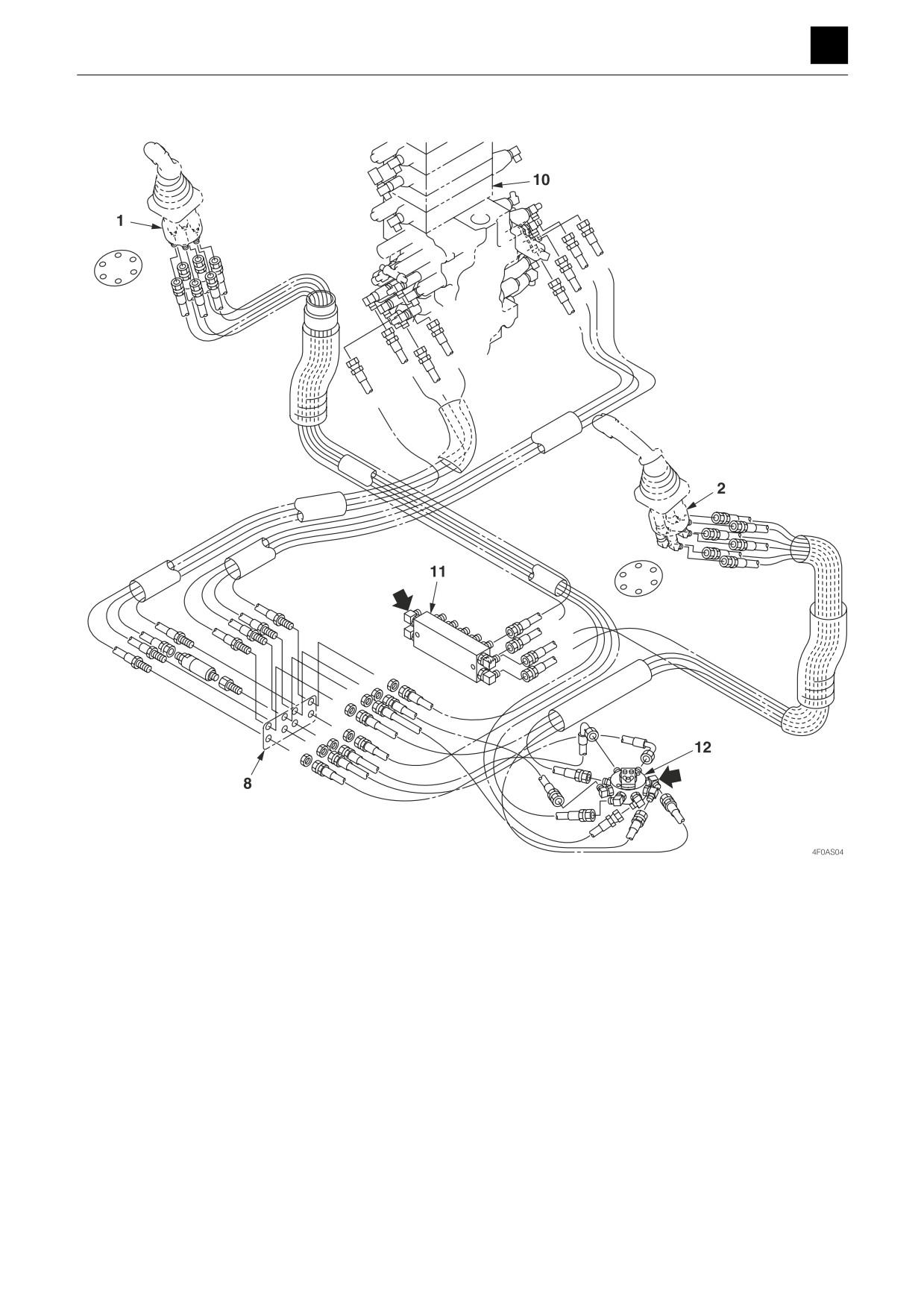
Table of connections
1
R1 ↔ J2
8
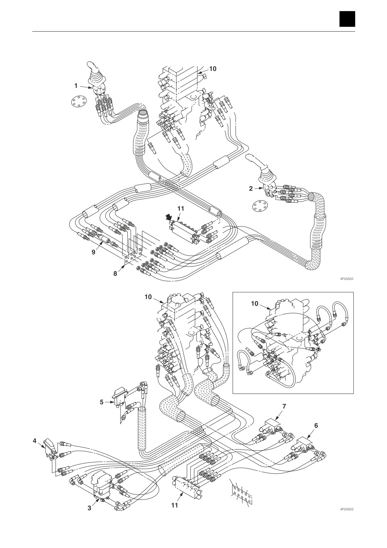
1. Pilot valve (Right)
1
R2 ↔ J4
8
2. Pilot valve (Left)
1
R3 ↔ J1
8
3. Pilot valve (Travel)
1
R4 ↔ J3
8
4. Pilot valve (Swing)
1
RP ↔ MP6
11
5. Pilot valve (Blade)
1
RT ↔ MT6
11
6. Solenoid valve (1st auxiliary line piping)
2
L1 ↔ J7
8
7. Solenoid valve (2nd auxiliary line piping)
2
L2 ↔ J5
8
8. Joint
2
L3 ↔ J8
8
9. Shockless valve
2
L4 ↔ J6
8
10. Control valve
2
LP ↔ MP7
11
11. Manifold
2
LT ↔ MT7
11
3
TR1 ↔ pa6
10
3
TR2 ↔ pb6
10
3
TR3 ↔ pa1
10
3
TR4 ↔ pb1
10
3
TRP ↔ MP2
11
3
TRT ↔ MT2
11
4
BS1 ↔ pra1
10
4
BS2 ↔ prb1
10
4
BSP ↔ TRP
3
4
BST ↔ TRT
3
5
BL1 ↔ prb2
10
5
BL2 ↔ pra2
10
5
BLP ↔ MP3
11
5
BLT ↔ MT3
11
6
SS11 ↔ pa2
10
6
SS12 ↔ pb2
10
6
SS1P ↔ MP5
11
6
SS1T ↔ MT5
11
7
SS21 ↔ pra3
10
7
SS22 ↔ prb3
10
7
SS2P ↔ MP4
11
7
SS2T ↔ MT4
11
8
J1 ↔ pa7
10
8
J2 ↔ pb7
10
8
J3 ↔ pa4
10
9
BSA ↔ pb8
10
8
J5 ↔ pa5
10
8
J6 ↔ pb5
10
8
J7 ↔ pa3
10
8
J8 ↔ pb3
10
10
pa4 ↔ pa8
10
10
pa5 ↔ pa9
10
10
pb5 ↔ pb9
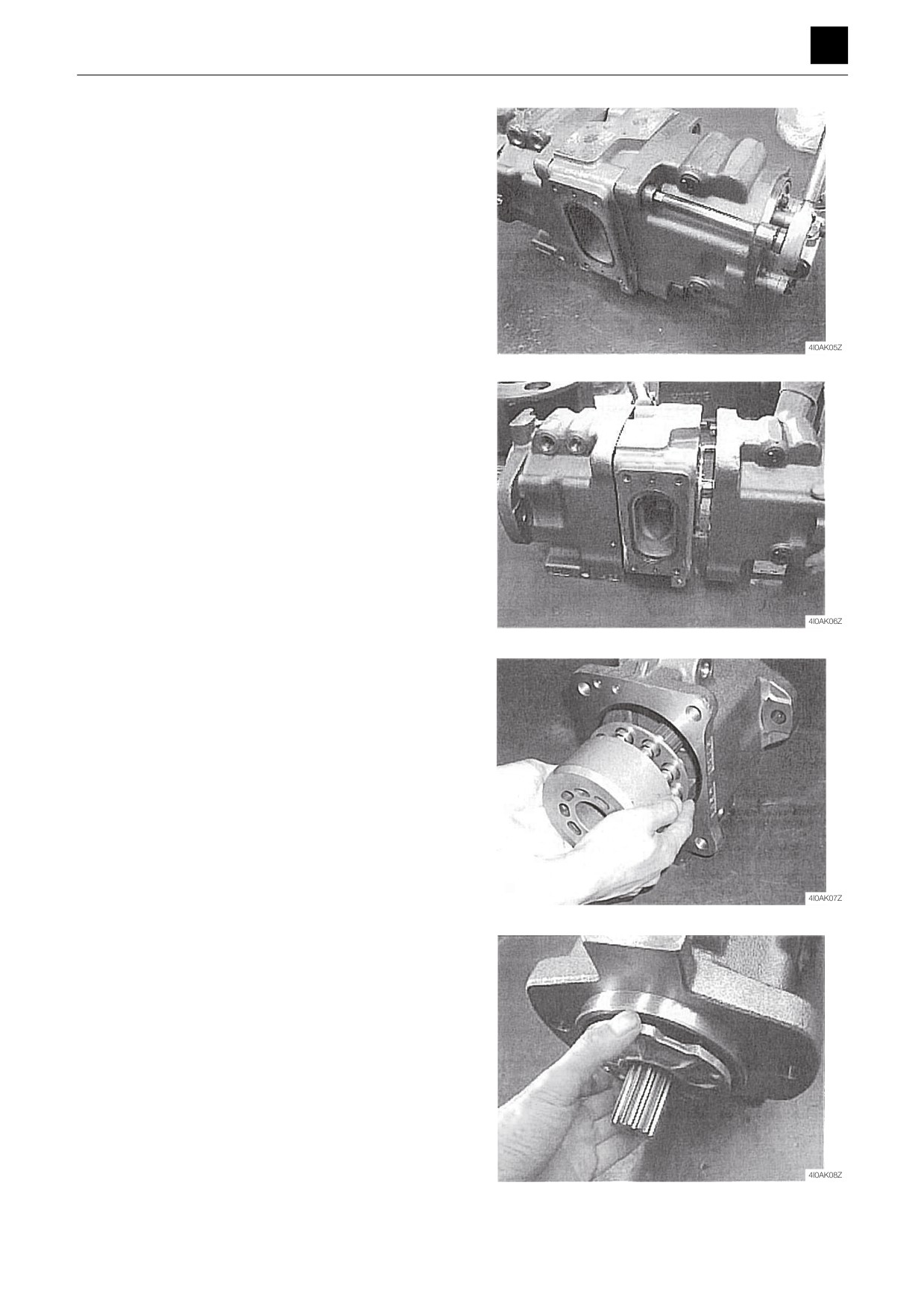
10
10
pc1 ↔ pb9
10
10
Pc2 ↔ pb8
10
10
Pc3 ↔ pa3
10
10
Pc3 ↔ pb3
10
3
OPERATING DEVICE
4F0AS00
DISASSEMBLY AND ASSEMBLY
4
OPERATING DEVICE
Type A (ISO) - Type G (JCB)
RP
R4
R3
Pa7
R1
Pa5
R2
RT
Pa4
Pa3
Pb5
Pb8
Pb3
Pb7
LP
L4
L3
a
L1
L2
MP6
LT
MT6
MP7
MT7
J7J5J3J1
S1
J2
J4
J6
J8
S4
SC
b
S2
SD
SB
S3
SA
4
OPERATING DEVICE
4F0AS00
DISASSEMBLY AND ASSEMBLY
4
OPERATING DEVICE
Pra3
Pra2
Pa8
Prb3
Pa9
Pra1
Prb2
Pa5
Pa4
Pc2
Prb1
Pc3
Pa6
Pa3
Pa2
Pb8
Pb9
Pc1
Pc3
Pa1
Pb6
Pb3
Pb9
Pb1
Pb5
BLT
Pb2
BLP
BL2
BL1
SS22
SS2P
SS2T
BST
SS21
BSP
SS12
SS1P
SS1T
SS11
BS1
TR4
BS2
TRT
MP2
TR3
MP3
MP4
MP5
TRP
MT2
TR1
MT3
MT4
TR2
MT5
5
OPERATING DEVICE
4F0AS00
DISASSEMBLY AND ASSEMBLY
4
OPERATING DEVICE
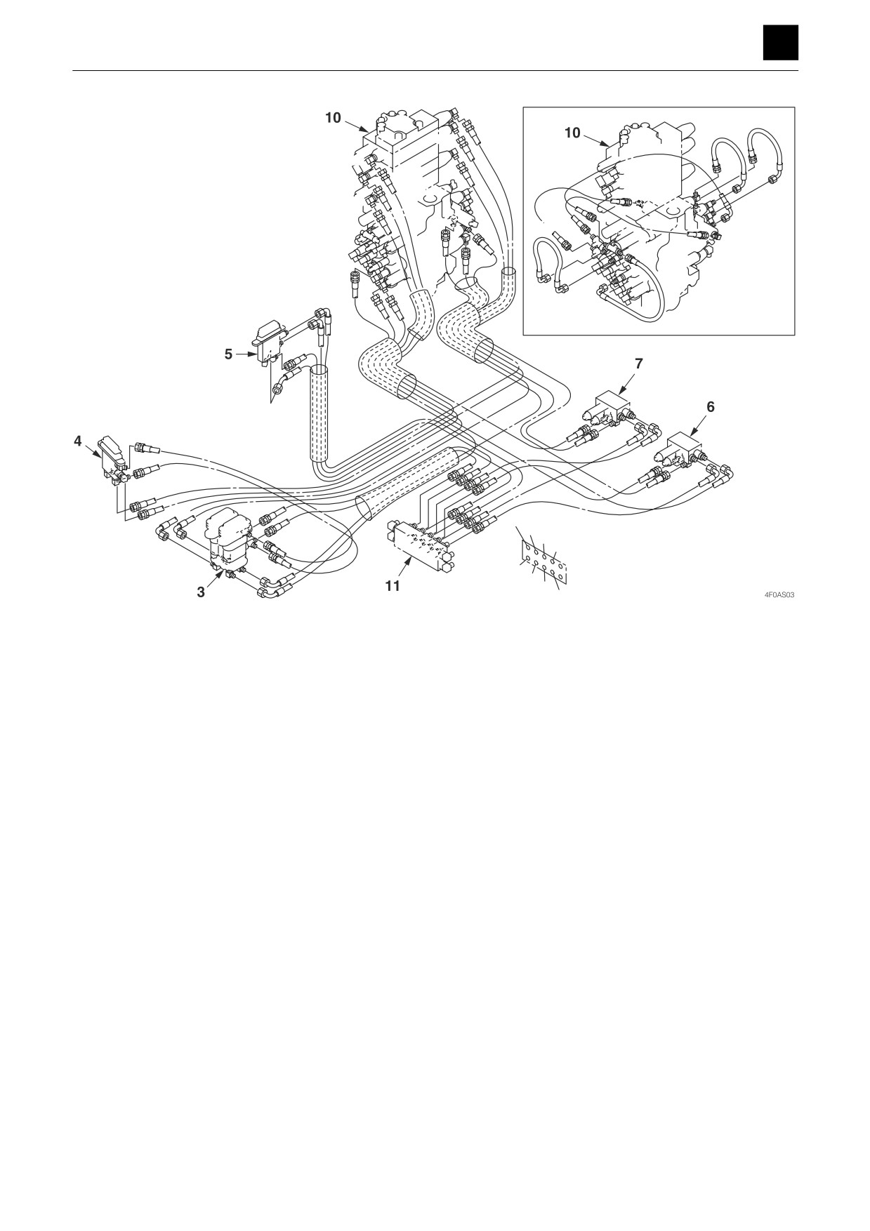
Table of connections
1
R1 ↔ J2
8
1. Pilot valve (Right)
1
R2 ↔ SA
12
2. Pilot valve (Left)
1
R3 ↔ J1
8
3. Pilot valve (Travel)
1
R4 ↔ SB
12
4. Pilot valve (Swing)
1
RP ↔ MP6
11
5. Pilot valve (Blade)
1
RT ↔ MT6
11
6. Solenoid valve (1st auxiliary line piping)
2
L1 ↔ J7
8
7. Solenoid valve (2nd auxiliary line piping)
2
L2 ↔ SC
12
8. Joint
2
L3 ↔ J8
8
9. Shockless valve
2
L4 ↔ SD
12
10. Control valve
2
LP ↔ MP7
11
11. Manifold
2
LT ↔ MT7
11
12. Selector valve
3
TR1 ↔ pa6
10
3
TR2 ↔ pb6
10
3
TR3 ↔ pa1
10
3
TR4 ↔ pb1
10
3
TRP ↔ MP2
11
3
TRT ↔ MT2
11
4
BS1 ↔ pra1
10
4
BS2 ↔ prb1
10
4
BSP ↔ TRP
3
4
BST ↔ TRT
3
5
BL1 ↔ prb2
10
5
BL2 ↔ pra2
10
5
BLP ↔ MP3
11
5
BLT ↔ MT3
11
6
SS11 ↔ pa2
10
6
SS12 ↔ pb2
10
6
SS1P ↔ MP5
11
6
SS1T ↔ MT5
11
7
SS21 ↔ pra3
10
7
SS22 ↔ prb3
10
7
SS2P ↔ MP4
11
7
SS2T ↔ MT4
11
12
S1 ↔ J4
8
12
S2 ↔ J3
8
12
S3 ↔ J5
8
12
S4 ↔ J6
8
8
J1 ↔ pa7
10
8
J2 ↔ pb7
10
8
J3 ↔ pa4
10
9
BSA ↔ pb8
10
8
J5 ↔ pa5
10
8
J6 ↔ pb5
10
8
J7 ↔ pa3
10
8
J8 ↔ pb3
10
10
pa4 ↔ pa8
10
10
pa5 ↔ pa9
10
10
pb5 ↔ pb9
10
10
pc1 ↔ pb9
10
10
pc2 ↔ pb8
10
10
pc3 ↔ pa3
10
10
pc3 ↔ pb3
10
6
OPERATING DEVICE
4F0AS00
DISASSEMBLY AND ASSEMBLY
4
OPERATING DEVICE
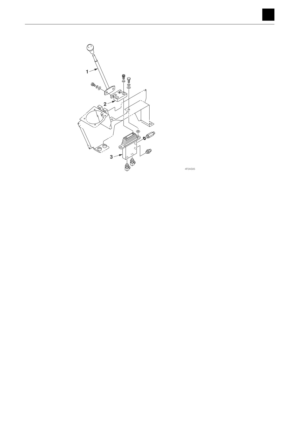
Dozer blade lever
1. Blade lever
2. Plate
3. Pilot valve (Blade)
7
OPERATING DEVICE
4F0AS00
DISASSEMBLY AND ASSEMBLY
4
OPERATING DEVICE
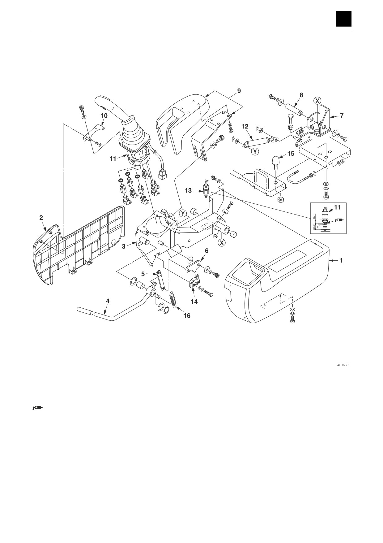
Lever stand
Pilot valve (Left)
1 Adjusting the limit switch: When the limit switch is in
the ON position, the tip of the switch should be visi-
ble from the boot.
Apply rubber grease #9106 (for natural rubber).
1. Panel (Main)
9. Elbow rest
2. Panel (Side)
10. Plate
3. Base
11. Pilot valve (Left)
4. Lever
12. Gas spring
5. Plate
13. Limit switch
6. Plate
14. Snatch lock
7. Bracket
15. Stopper
8. Shaft
16. Spring
8
OPERATING DEVICE
4F0AS00
DISASSEMBLY AND ASSEMBLY
4
OPERATING DEVICE
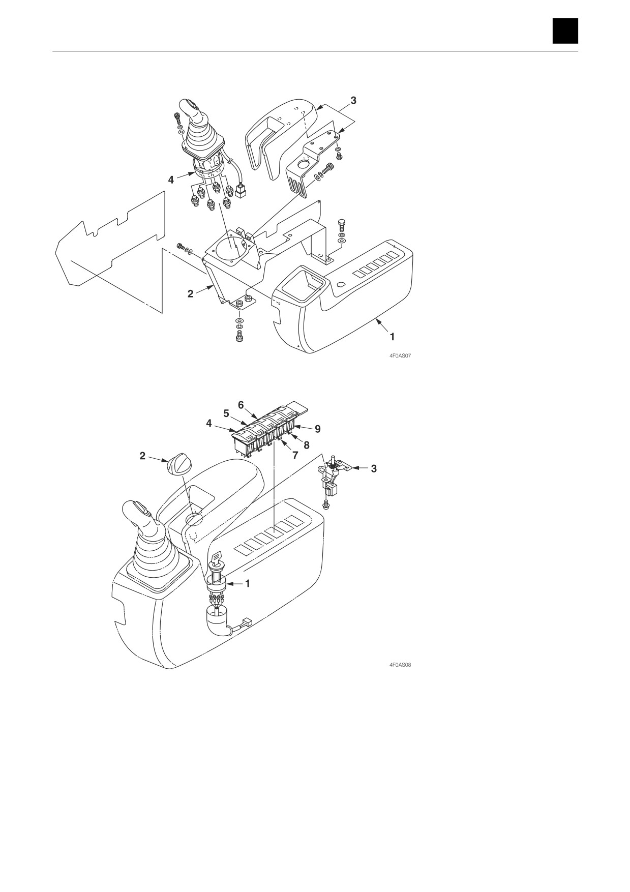
Pilot valve (Right)
1. Panel (Main)
2. Base
3. Elbow rest
4. Pilot valve (Right)
Control box R
1. Starter switch
2. Knob
3. Variable resistor
4. Switch
5. Switch
6. Switch
7. Switch
8. Switch
9. Ornament
9
OPERATING DEVICE
4F0AS00
DISASSEMBLY AND ASSEMBLY
4
ATTACHMENTS
ATTACHMENTS
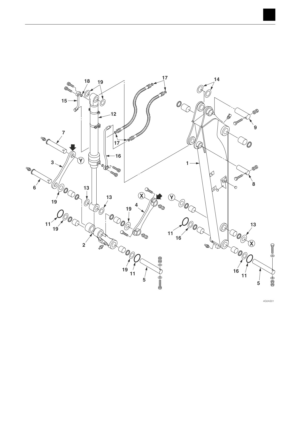
Hoe attachment
Construction
1. Arm
11. O-ring
2. Link arm
12. Bucket cylinder
3. Guide link R
13. Shim
4. Guide link L
14. Shim
5. Pin
15. Pipe
6. Pin
16. Pipe
7. Pin
17. O-ring
8. Pin
18. O-ring
9. Pin
19. Shim (Selected usage)
1
ATTACHMENTS
4G0AS00
DISASSEMBLY AND ASSEMBLY
4
ATTACHMENTS
X
X
Y
Y
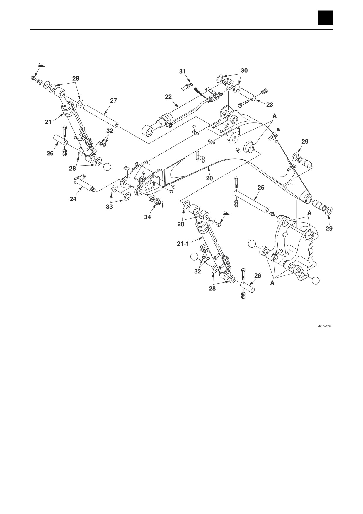
A: Apply NEVER-SEEZ lubricant to the pin insertion hole
and then insert the pin into the hole.
20. Boom
27. Pin
21. Boom cylinder R
28. Shim (Selected usage)
21-1. Boom cylinder L
29. Shim (Selected usage)
22. Arm cylinder
30. Shim (Selected usage)
23. Pin
31. O-ring
24. Pin
32. O-ring
25. Pin
33. Shim (Selected usage)
26. Pin
34. Castle nut
2
ATTACHMENTS
4G0AS00
DISASSEMBLY AND ASSEMBLY
4
ATTACHMENTS
PIL
T
X
X
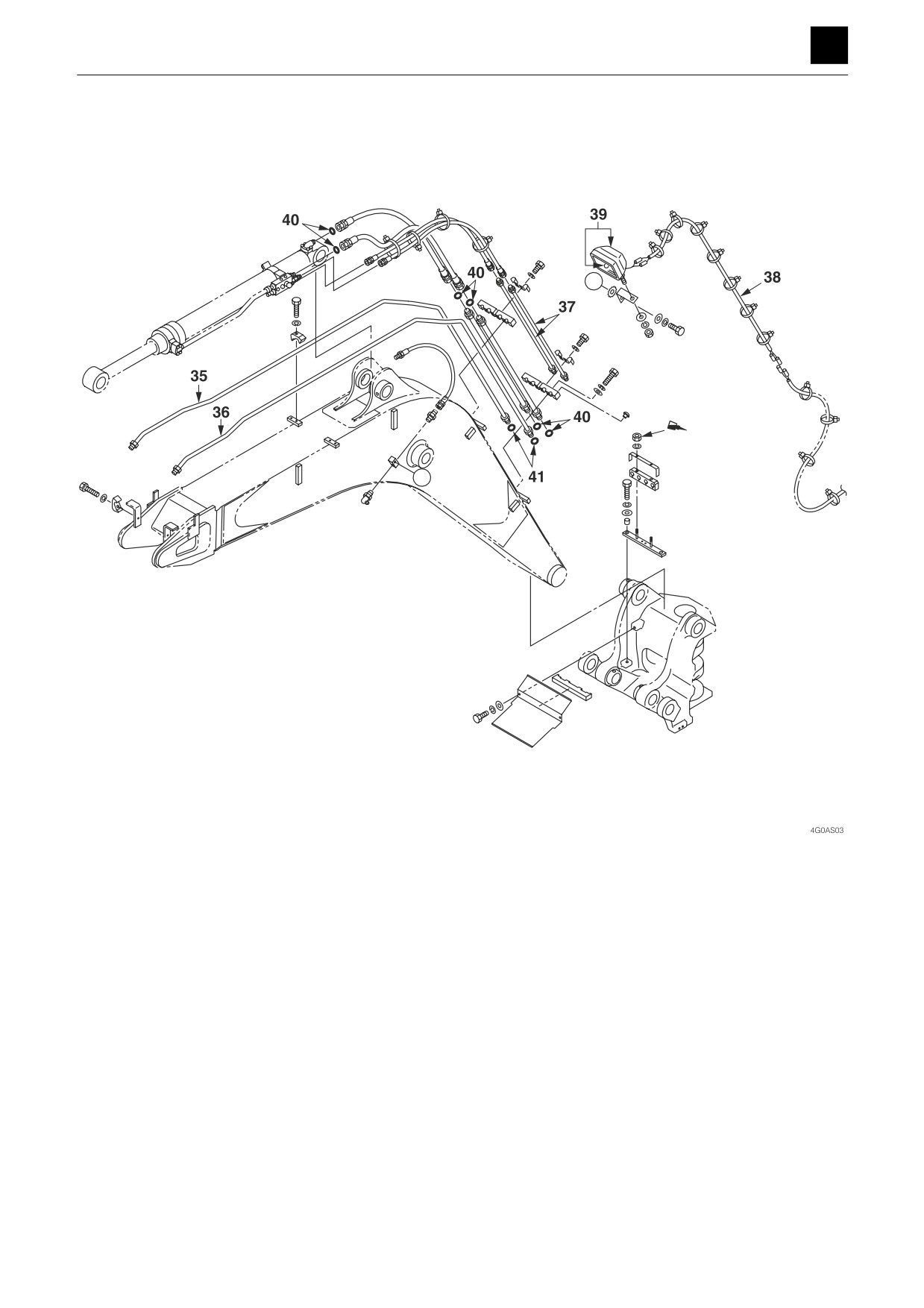
35. Bucket pipe R
36. Bucket pipe L
37. Arm pipe
38. Wire harness
39. Working lamp
40. O-ring
41. O-ring
3
ATTACHMENTS
4G0AS00
DISASSEMBLY AND ASSEMBLY
4
ATTACHMENTS
X
X
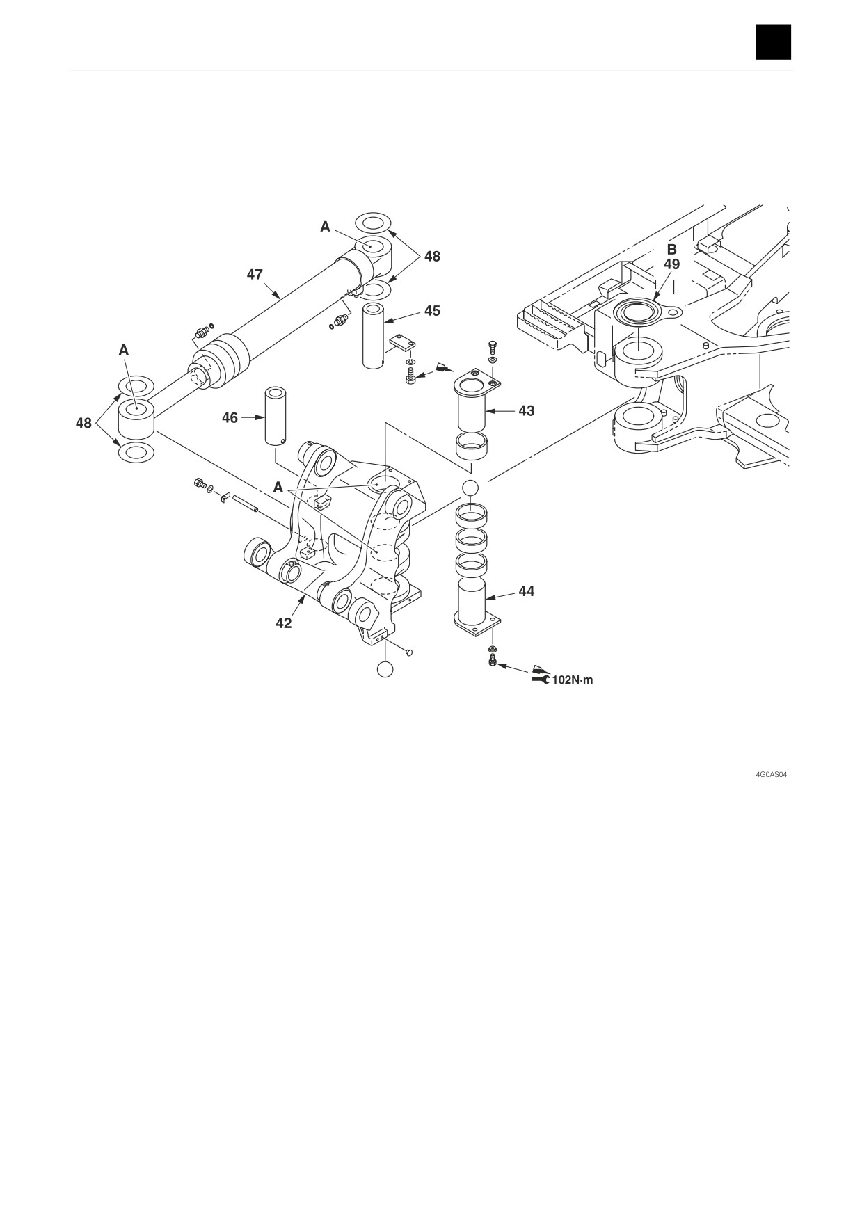
A: Apply NEVER-SEEZ lubricant to the pin insertion hole
and then insert the pin into the hole.
B: Attach the washer with the side with the grease
groove facing upward (toward the bracket side).
42. Boom bracket
43. Pin
44. Pin
45. Pin
46. Pin
47. Swing cylinder
48. Shim (Selected usage)
49. Washer (Selected usage)
4
ATTACHMENTS
4G0AS00
DISASSEMBLY AND ASSEMBLY
4
ATTACHMENTS
X
X
Y
Y
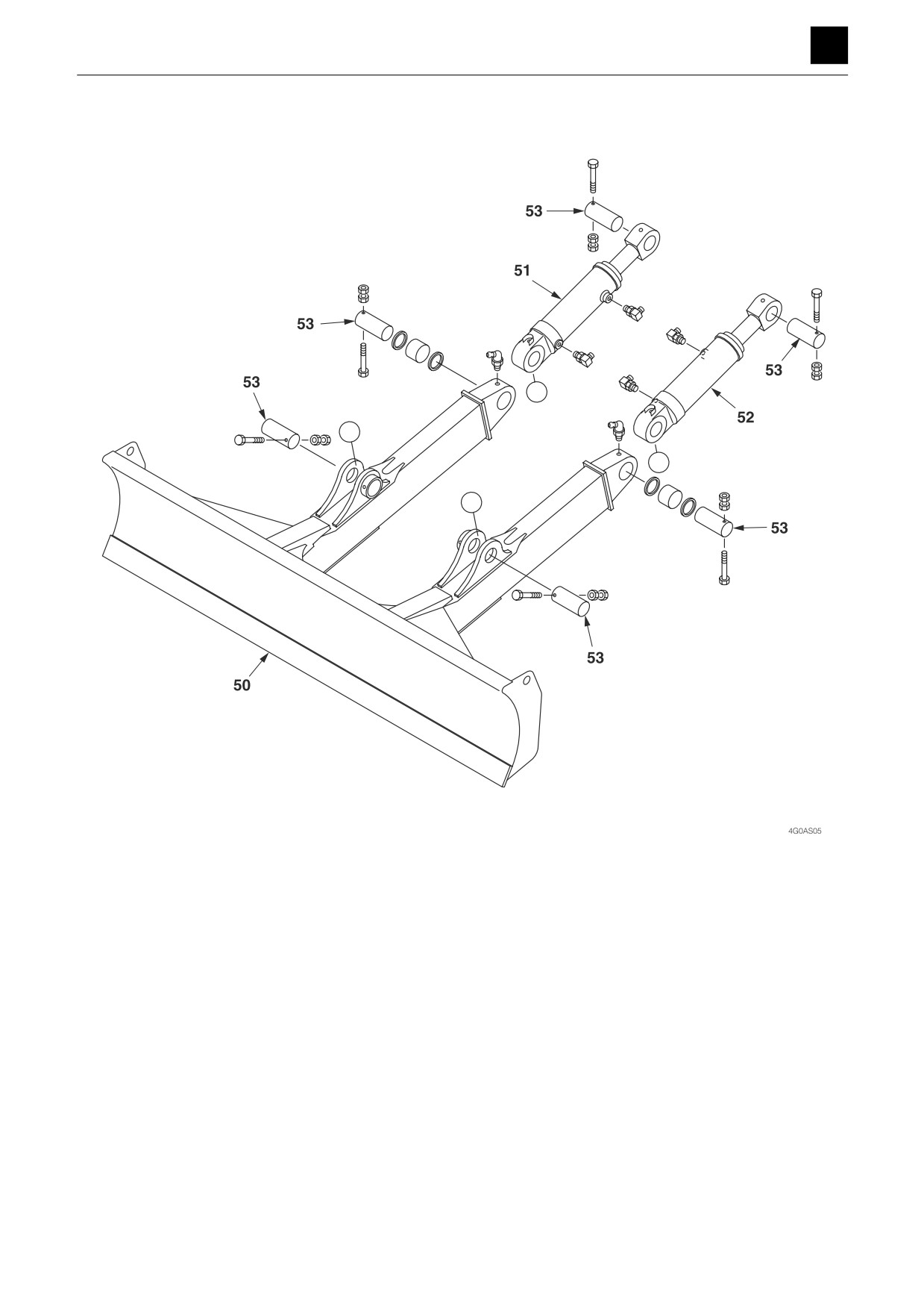
50. Blade
51. Blade cylinder R
52. Blade cylinder L
53. Pin
5
ATTACHMENTS
4G0AS00
DISASSEMBLY AND ASSEMBLY
4
ATTACHMENTS
Removing the hoe attachment
WARNING
• Be sure to release any residual pressure in the piping
before disconnecting the hydraulic hose.
• Do not attempt to insert any fingers into the hole when
adjusting the pin hole position.
Important:
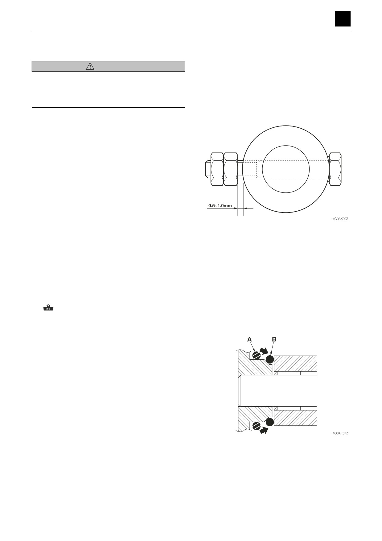
• When tightening the lock bolt with a double nut, allow a
clearance of 0.5 mm to 1.0 mm (0.0197 in. to 0.0394
in.) between the nut and the lock collar.
• Adjust the clearance for the pin connector to a width of
between 0.2 mm to 0.5 mm (0.0079 in. to 0.0197 in.)
using a shim.
• Be sure to bleed the air from the cylinder before starting
operation for the first time after reassembling hydraulic
devices such as the hydraulic cylinder or hydraulic pip-
ing.
The numbers in parentheses, ( ), listed after the names of
parts throughout this document are used to refer to the
same parts as the numbers listed in the construction di-
agram and parts lists.
Removing the bucket
1. Orient the back of the bucket downward, and lower
the bucket all the way down to the ground.
2. Take out the bolts, and remove the pins.
3. Remove the bucket.
Bucket: 305 kg (670 lb)
Installing the bucket
To install, follow the same procedures as for removal but
in the reverse order.
Before beginning attachment of the bucket, place the O-
ring in the temporary placement position “A” in the outer
circumference of the bucket bushing, and move it to the
specified position “B” after completing attachment.
6
ATTACHMENTS
4G0AS00
DISASSEMBLY AND ASSEMBLY
4
ATTACHMENTS
Removing the link
• Completely retract the bucket cylinder, and lower the
tip of the arm to the ground.
1. Take out the pin (6), and remove the link arm (2).
a. Guide links R (3) and L (4)
Exercise caution as
they may drop
b. Cylinder (12)
Place on the skid
c. Link arm (2)
Suspend temporarily
2. Take out the pin (7), and remove the guide links R (3)
and L (4).
Installing the link
To install, follow the same procedures as for removal but
in the reverse order.
Removing the arm
1. Disconnect the hydraulic hoses from the bucket cyl-
inder (12).
Next, disconnect the hydraulic hoses from the auxil-
iary line ports.
2. Suspend the bucket cylinder (12) temporarily and
then pull out the pin (8) and remove the bucket cylin-
der.
Bucket cylinder: 94 kg (205 lb)
3. Place the skid under the arm cylinder (22), and re-
move the pin (9).
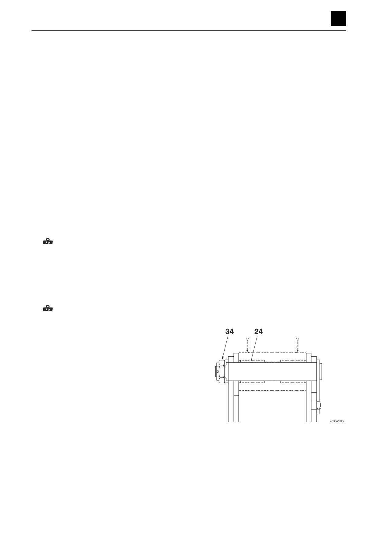
4. Take out the cotter pin, and remove the castle nut
(34).
5. Suspend the arm (1) temporarily and then pull out the
pin (24) and remove the arm.
Arm: 273 kg (600 lb)
Installing the lift arm
To install, follow the same procedures as for removal but
in the reverse order.
Important:
When securing the arm with the fixing pin (24) and castle
nut (34), make sure not to tighten the castle nut (34) too
much.
After tightening down the castle nut (34) with a hand, firm-
ly tighten it down until the tightening hole positions for the
fixing pin (24) and cotter pin for the castle nut (34) line up
properly.
7
ATTACHMENTS
4G0AS00
DISASSEMBLY AND ASSEMBLY
4
ATTACHMENTS
Removing the boom
Lower the tip of the boom all the way to the ground.
1. Disconnect the hydraulic hoses from the arm cylin-
der (22).
2. Suspend the arm cylinder (22) temporarily and then
pull out the pin (23) and remove the arm cylinder.
Arm cylinder: 147 kg (325 lb)
3. Remove the boom cylinders.
a. Disconnect the hydraulic pipings from the boom
cylinders R (21) and L (21-1).
b. Remove the covers and plates from the boom cyl-
inders R and L.
c. Suspend the boom cylinder R (21) temporarily.
d. Push in the pin (27), and disconnect the rod side
of the cylinder and lower the cylinder to the
ground.
• Push in the pin (27) only until the rod becomes
disconnected.
e. Suspend the boom cylinder L (21-1) temporarily
and then remove the pin (27) and lower the rod
side of the cylinder all the way to the ground.
f. Suspend the boom cylinder R (21) temporarily,
disconnect the head side from the head pin (26),
and raise the cylinder.
Boom cylinder: 110 kg (245 lb)
g. Suspend the boom cylinder L (21-1) temporarily,
take out the head pin (26), and raise the cylinder
as in the above step.
4. Disconnect the electrical wiring (38) to the boom light
from the wiring on the machine body side.
5. Disconnect the hydraulic hoses connected from the
machine body side from the pipes.
6. Suspend the boom (20) temporarily and then pull out
the pin (25) and remove the boom.
Boom: 669 kg (1475 lb)
Installing the boom
To install, follow the same procedures as for removal but
in the reverse order.
8
ATTACHMENTS
4G0AS00
DISASSEMBLY AND ASSEMBLY
4
ATTACHMENTS
Removing the swing bracket
1. Remove the cover and clamp from the boom bracket
(42).
2. Remove the plate, take out the pin (46), and discon-
nect the swing cylinder (47) from the swing bracket.
3. Suspend the boom bracket (42) temporarily and then
pull out the pins (43) and (44) and remove the swing
bracket.
• Be careful not to damage the hoses when working
with them.
Pin insertion bolt: 102 N·m (75.2 ft.-lb)
Boom bracket: 497 kg (1095 lb)
Installing the swing bracket
To install, follow the same procedures as for removal but
in the reverse order.
• During assembly, apply NEVER-SEEZ NS lubricant (an
anti-seizing lubricant) to the fixing pin holes on the
swing bracket and then insert the pins (46) and (45)
into the appropriate holes.
• Attach the washer (49) with the side with the grease
groove facing upward (toward the boom bracket side).
9
ATTACHMENTS
4G0AS00
DISASSEMBLY AND ASSEMBLY
4
ATTACHMENTS
Removing the blade
Lower the blade all the way down to the ground.
1. Disconnect the hydraulic hoses from the blade cylin-
ders R (51) and L (52).
2. Suspend the blade cylinder R (51) temporarily and
then take out the pins (53) and remove the blade cyl-
inder.
Next, remove the blade cylinder L in the same way as
for the blade cylinder R.
Blade cylinder R: 61 kg (135 lb)
3. Suspend the blade (50) temporarily and then take
out the pins (53) and remove the blade (50).
Blade: 567 kg (1250 lb)
Installing the blade
To install, follow the same procedures as for removal but
in the reverse order.
10
ATTACHMENTS
4G0AS00
DISASSEMBLY AND ASSEMBLY
4
ATTACHMENTS
Adjusting the clearance between the bucket and arm (Equipment)
WARNING
• Set all movable equipment against the ground or in the
lowermost position possible before performing mainte-
nance or repairs under the machine.
• When adjusting clearances, secure all relevant equip-
ment to prevent any accidental movement.
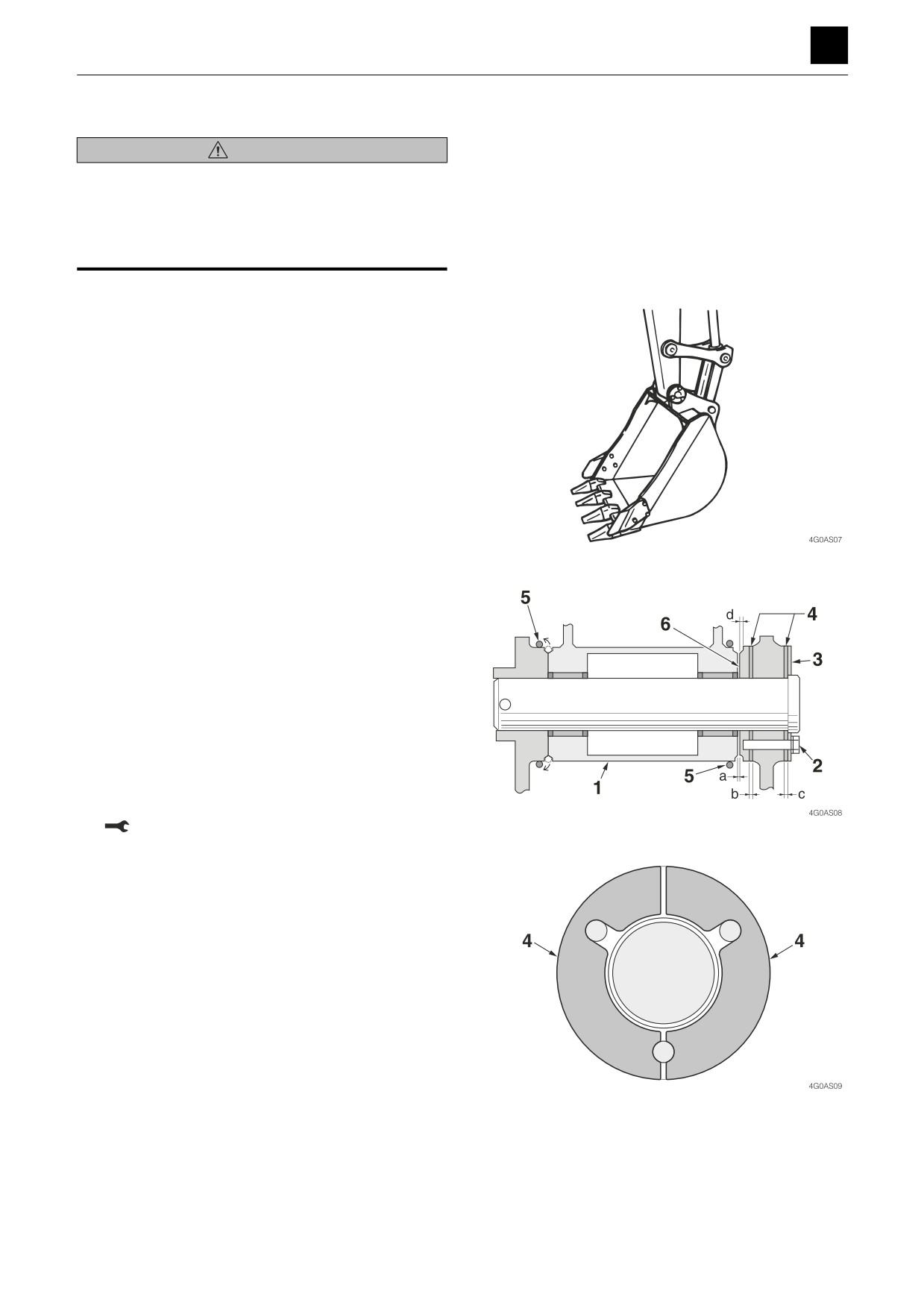
1. Lower the bucket all the way to the ground in a stable
position as shown in the above diagram.
2. Slew the upper structure slightly to the left, and lightly
push the arm toward the leftside of the bucket. (To-
ward the side without an adjuster.)
3. Set the safety lock lever in the locked position, and
stop the engine.
4. Loosen the three bolts (2) slightly using a wrench,
and remove the shim from the clearance C between
the blade (3) and the bucket. The shim is split into
two parts. Insert a screwdriver into the seam be-
tween the left and right shims and loosen the bolt
slightly to make it easier to remove the shims.
5. Move the O-ring (5) over, and measure the width of
the clearance (a).
6. To eliminate the clearance (a), push down on the
head of the bolt (2) with a finger. Pushing down on
the head of the bolt causes the clearance (b) to be-
come wider. Insert enough of the shims removed in
the above step into the clearance (b) as will go in
comfortably.
7. Insert the rest of the shims into the clearance (c) and
then tighten down the bolt to secure everything in
place.
Bolt: 83 N·m (61.5 ft.-lb)
This completes the clearance adjusting procedure.
Supplementary notes: The number of shims used for the
T clearances (b) and (c) is two sets of six or twelve total.
If the shim to be inserted into clearance (c) in 7. above is
omitted and forgotten, the end of the bolt (2) may jut past
the boss (6). If this occurs, the boss on the end of the arm
may be damaged or the bolt may break in two. If the end
surface of the boss (6) becomes worn and the width of
the groove for the O-ring exceeds 5 mm (0.2 in.), replace
the existing boss with a new one.
11
ATTACHMENTS
4G0AS00
DISASSEMBLY AND ASSEMBLY
4
HYDRAULIC TANK
HYDRAULIC TANK
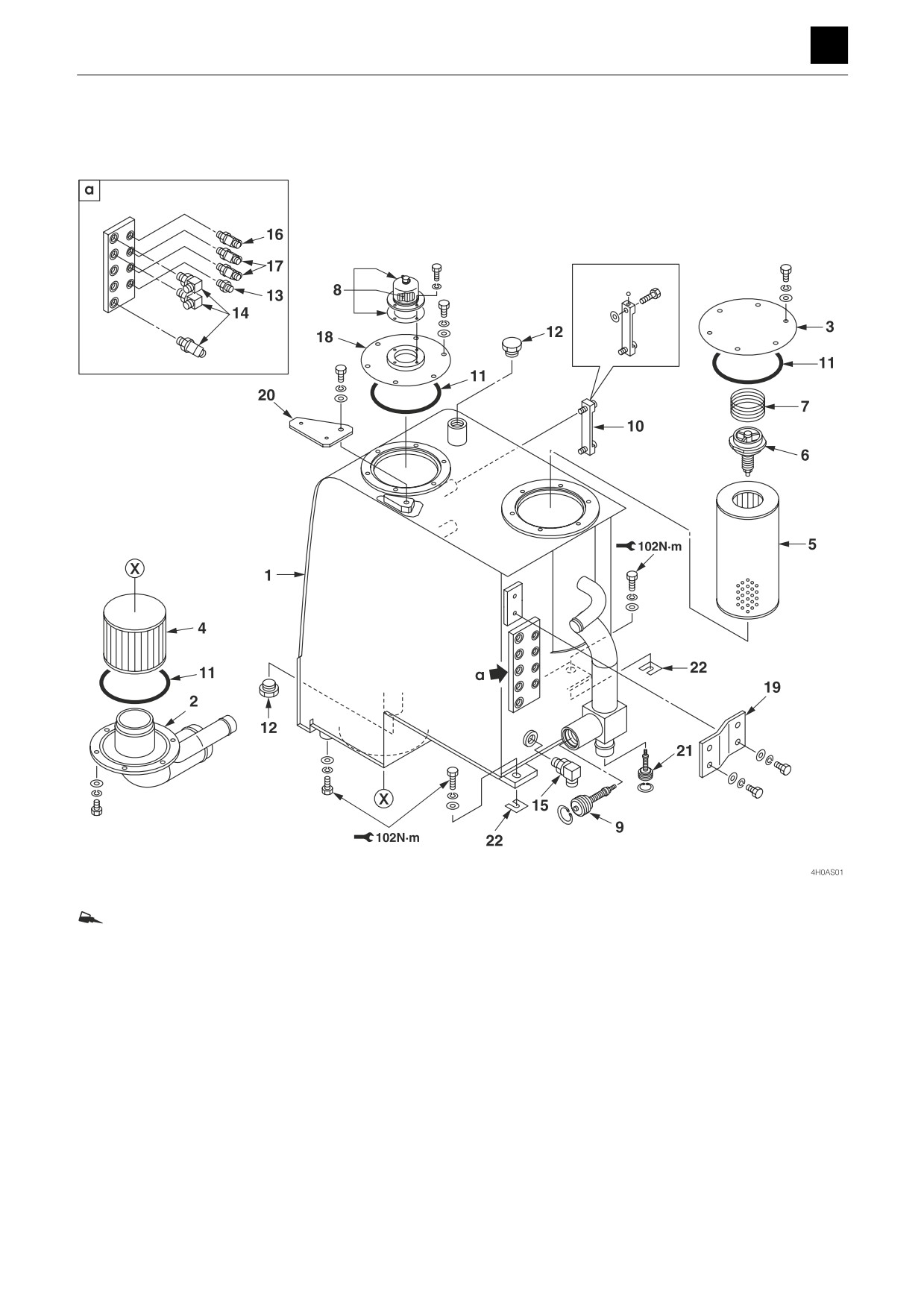
ThreeBond #1324
1. Hydraulic tank
9. Check valve
16. Elbow
2. Suction pipe
10. Sight gauge
17. Elbow
3. Cover
11. O-ring
18. Cover
4. Suction filter
12. Plug
19. Bracket
5. Return filter
13. Adapter
20. Plate
6. Relief valve
14. Elbow
21. Check valve
7. Spring
15. Adapter
22. Spacer (Selected usage)
8. Air breather
1
HYDRAULIC TANK
4H0AS00
DISASSEMBLY AND ASSEMBLY
4
HYDRAULIC TANK
Removing the hydraulic tank
The numbers in parentheses ( ), listed after the names of
parts throughout this document are used to refer to the
same parts as the numbers listed in the construction di-
agram and parts lists.
1. Remove the covers from the perimeter around the
hydraulic tank.
“Removing the covers”
2. Drain the hydraulic oil from the hydraulic tank (1).
a. Push the button on the air breather (8) to release
the internal pressure in the hydraulic tank.
b. Loosen the drain plug (12), and drain out the oil.
• Tank level capacity: 95 L (25.1 US gal.)
3. Disconnect the low-pressure hoses from the hydrau-
lic tank.
4. Disconnect the high-pressure hoses from the hy-
draulic tank.
• Attach an identification tag on each hoses to avoid
mixing them up during reassembly.
5. Take out the bolts holding the hydraulic tank in place,
and suspend the hydraulic tank and remove it.
• During assembly, if any clearance exists between
the attachment surfaces of the machine body and
the hydraulic tank, insert a spacer (22) to get rid
of the clearance.
Bolt: ThreeBond #1324
Bolt: 102 N·m (75.2 ft.-lb)
Hydraulic tank: 94 kg (205 lb)
Installing the hydraulic tank
For installation of the hydraulic tank, follow the same pro-
cedures as for removal but in the reverse order.
2
HYDRAULIC TANK
4H0AS00
DISASSEMBLY AND ASSEMBLY
4
HYDRAULIC TANK
Inspecting and refilling the oil in the hydraulic tank
WARNING
• Oil may spurt out if caps or filters are removed or pipes
are disconnected before the pressure in the hydraulic
system is released.
• Push the button on the air breather (8) to release the in-
ternal pressure in the hydraulic tank.
Inspection
The oil level changes with the oil temperature. Inspect
the oil while maintaining the machine at the attitude
shown in the figure.
Machine attitude for inspecting the hydraulic oil level
1. Start the engine, and run it at low speed.
2. Fully retract the arm cylinder and the bucket cylinder,
and then lower the bucket to the ground.
3. Stop the engine.
4. Inspect the oil level using the sight gauge (10).
When the oil temperature is about 20°C (68°F): The
level should be halfway between the upper limit (H)
and the lower limit (L). If it is below the lower limit (L),
replenish.
When the oil temperature is about 50 to 80°C (122 to
176°F): The level should be near the upper limit (H).
Refilling the oil
Important: Do not refill to above the (H) mark. Doing so
may cause damage to the hydraulic circuit or cause oil to
spurt out. If the oil level is accidentally filled to above the
(H) mark, stop the engine and allow the hydraulic oil to
cool down before draining off the excess oil from the drain
plug (12).
Important: Failure to pressurize the hydraulic tank may
cause the pump to suck in air, which will adversely affect
the hydraulic units.
1. Push the button on the air breather to release the in-
ternal pressure in the hydraulic tank, and remove the
tank.
2. Add oil to the tank up to the halfway point on the side
gauge (10).
Bleeding off the air
Important: After replacing the hydraulic oil, bleed the air
from the hydraulic circuits and hydraulic devices. Failure
to do so may damage the hydraulic devices.
3
HYDRAULIC TANK
4H0AS00
DISASSEMBLY AND ASSEMBLY
4
HYDRAULIC TANK
Hydraulic pump
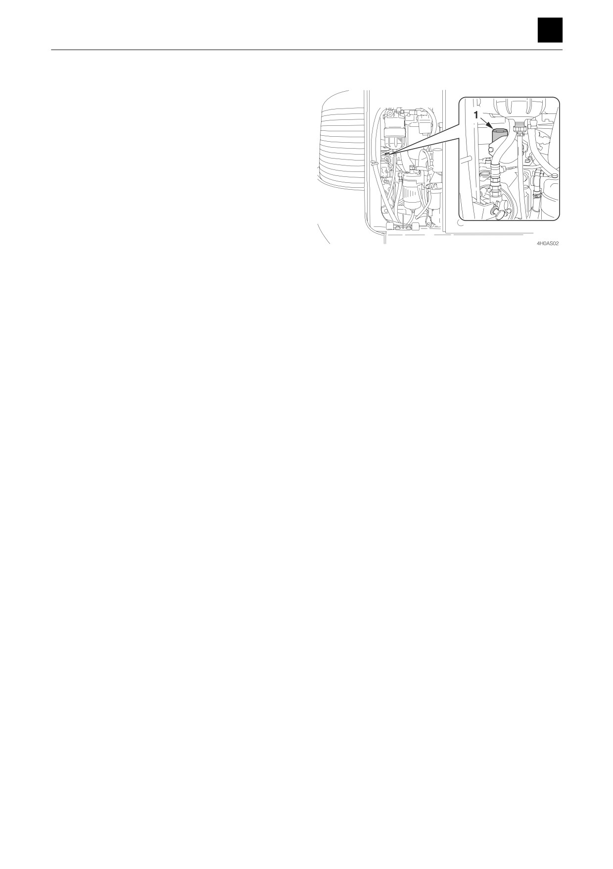
1. Loosen the plug (1) used for bleeding air from the hy-
draulic pump.
2. Tighten the plug (1) once the hydraulic oil overflows
from the plug hole.
If the boom and arm are not operating normally, there
may be air trapped in the lines or parts listed below.
4
HYDRAULIC TANK
4H0AS00
DISASSEMBLY AND ASSEMBLY
4
HYDRAULIC TANK
Emergency shut-off valve
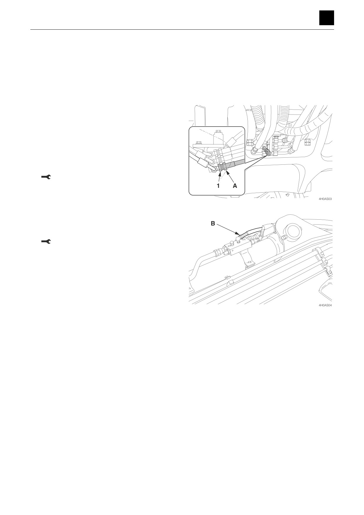
1. Place a receptacle under hose (A) or hose (B) to
catch waste oil that is drained out.
2. Start the engine, and let it run at a low-idling speed.
3. Move the safety lock lever to the full-release position.
a. Boom
4. Secure the hose fitting (A) in place with a wrench to
keep it from moving and then slowly loosen the hose
nut (1).
5. Slowly move the boom downward little by little until
air bubbles no longer escape from the hose nut (1)
connector.
6. Secure the hose fitting (A) in place with a wrench to
keep it from moving and then tighten the hose nut (1).
: 50 N·m (36.9 ft.-lb)
b. Arm
7. Slowly loosen the hose (B).
8. Slowly pull the arm outward little by little until air bub-
bles no longer escape from the hose (B) connector.
9. Screw the hose (B) back on.
: 50 N·m (36.9 ft.-lb)
Slew motor and cylinder
1. Start the engine, and let it run at a low-idling speed
for 10 minutes.
2. With the engine left idling, extend and retract each
cylinder 4 or 5 times without letting any reach the
stroke end.
3. Slowly slew the machine to the left and right several
times.
4. Run the engine at high speed and then extend and
retract each cylinder 4 or 5 times without letting any
reach the stroke end.
5. Slew the machine to the left and right several times.
6. Return the engine speed to low idle and then extend
and retract each cylinder 4 or 5 times without letting
any reach the stroke end.
5
HYDRAULIC TANK
4H0AS00
DISASSEMBLY AND ASSEMBLY
4
HYDRAULIC PUMP (MAIN)
HYDRAULIC PUMP (MAIN)
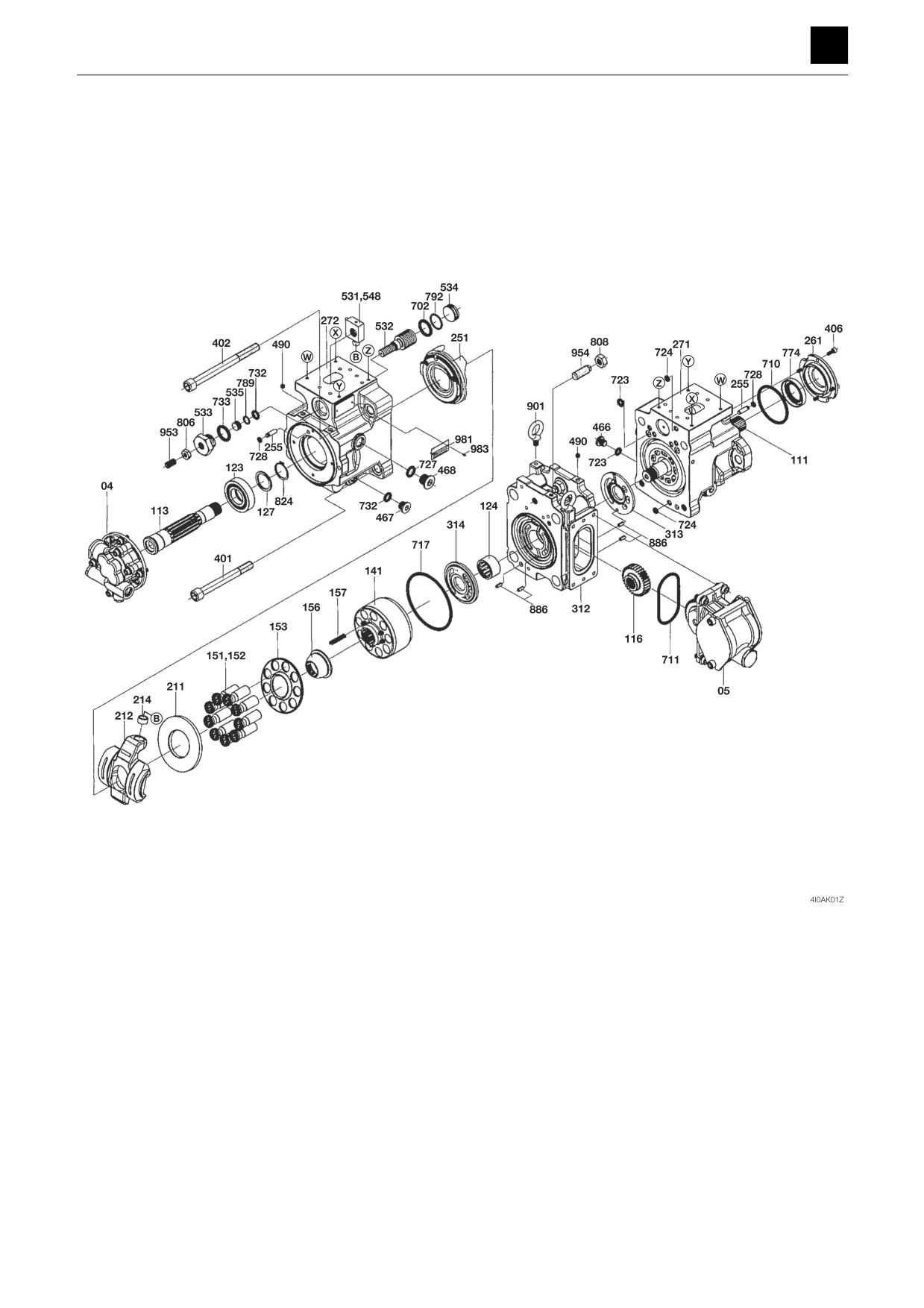
Construction
04. Gear pump
156. Bushing
314. Valve plate L
535. Stopper S
774. Oil seal
05. PTO unit
157. Spring
401. Cap screw
548. Pin
789. Backup ring
111. Shaft
211. Shoe plate
402. Cap screw
702. O-ring
792. Backup ring
113. Shaft
212. Swash plate
406. Cap screw
710. O-ring
806. Nut
116. First gear
214. Bushing
466. Plug
711. O-ring
808. Nut
123. Bearing
251. Support
467. Plug
717. O-ring
824. Ring
124. Needle bearing
255. Pin
468. Plug
723. O-ring
886. Spring pin
127. Spacer
261. Cover
490. Plug
724. O-ring
901. Screw
141. Cylinder block
271. Casing F
531. Pin
727. O-ring
953. Adjusting screw
151. Piston
272. Casing R
532. Servo piston
728. O-ring
954. Adjusting screw
152. Seal
312. Block
533. Plug
732. O-ring
983. Pin
153. Plate
313. Valve plate R
534. Stopper L
733. O-ring
1
HYDRAULIC PUMP (MAIN)
4I0AS00
DISASSEMBLY AND ASSEMBLY
4
HYDRAULIC PUMP (MAIN)
Disassembly and assembly
The numbers in parentheses, ( ), listed after the names of
parts throughout this document are used to refer to the
same parts as the numbers listed in the construction di-
agram and parts lists.
General precautions
•
Perform disassembly and assembly work in a clean
place. Provide clean containers to hold parts during
disassembly.
•
Clean around the ports before disassembly. Remove
paint around connectors with a wire brush.
•
Clean the disassembled parts with wash oil.
•
Put alignment marks on all parts to ensure that they are
reassembled in the same positions.
•
After each disassembly, replace all seals and apply a
thin layer of grease to each.
•
Check each part for abnormal wear or seizing. Re-
move any burrs with sandpaper.
•
Remove adhesive from screw holes that use adhesive
through the tap. Do not reuse mounting bolts or
screws.
•
Do not use cloth gloves during assembly. Fibers from
the gloves could fall off and clog valves, etc., which
could cause parts to become faulty.
•
During assembly, be sure to apply clean hydraulic oil
to all moving parts in and sliding parts that come into
contact with the hydraulic motor and valve parts be-
fore installing or attaching the part.
•
Plug all ports once assembly has been completed in
order to prevent dust and dirt from entering.
•
Do not attempt to adjust the adjusting screws at times
other than when necessary.
2
HYDRAULIC PUMP (MAIN)
4I0AS00
DISASSEMBLY AND ASSEMBLY
4
HYDRAULIC PUMP (MAIN)
Disassembly
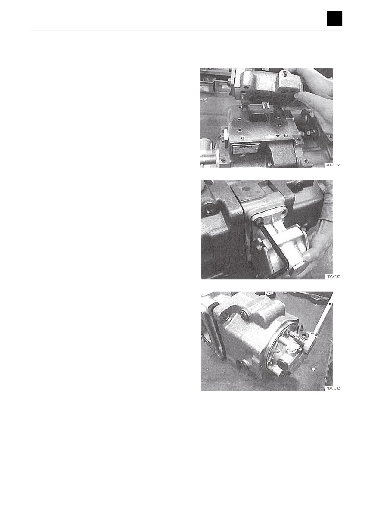
1. Remove the plug (468), and all the oil to drain out
from the casings (271) and (272).
2. Take out the cap screws, and remove the regulator.
3. Take out the cap screws, and remove the PTO unit
(05).
4. Take out the cap screws, and remove the gear pump
(04).
3
HYDRAULIC PUMP (MAIN)
4I0AS00
DISASSEMBLY AND ASSEMBLY
4
HYDRAULIC PUMP (MAIN)
5. Take out the cap screws, and disassemble the cas-
ings (271) and (272) and the valve block (274).
6. Remove the first gear (116) from the valve block
(274).
7. Remove the cylinder block (141), the piston (151),
the shoe (152), the plate (153), the bushing (156),
and the spring (157) from the casings (271) and
(272).
8. Take out the cap screws, and remove the cover
(261).
• Insert a flat-bladed screwdriver into the notched
groove on the cover and use it to pry open the
cover to remove.
• Be careful not to damage the oil seal (774) for the
cover.
4
HYDRAULIC PUMP (MAIN)
4I0AS00
DISASSEMBLY AND ASSEMBLY
4
HYDRAULIC PUMP (MAIN)
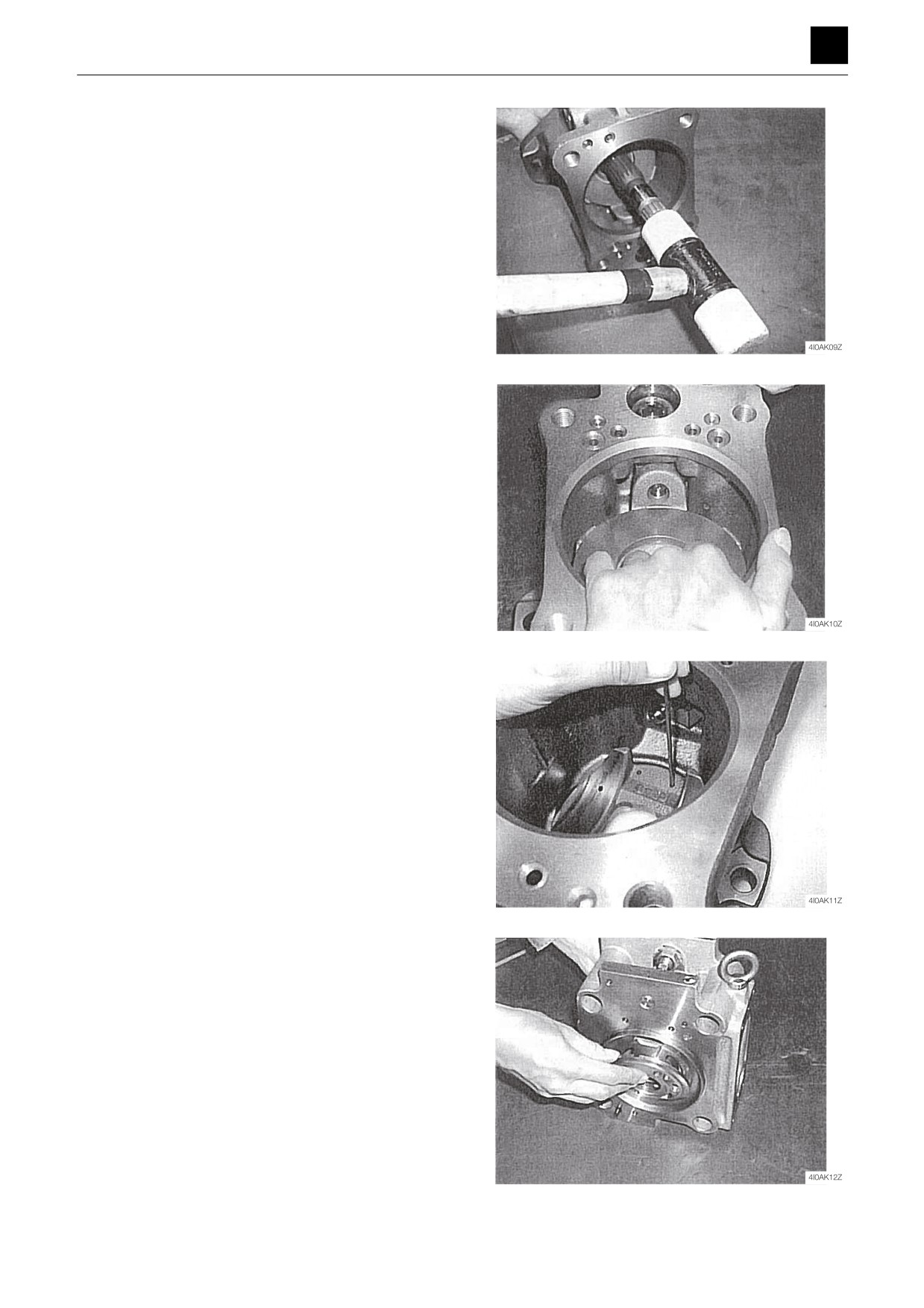
9. Lightly tap on the rear ends of the shafts (111) and
(113) to remove the shafts from the casings (271)
and (272).
10. Remove the shoe plate (211) and swash plate (212)
from the casings (271) and (272).
11. Remove the pin (255) from the support (251).
• Push it out using a piece of wire or other object.
• When pushing the wire into the hole, make sure
not to confuse the pin insertion hole with the oil
supply line for the support.
• If the O-ring (728) has hardened, making it diffi-
cult to remove the pin, lightly tap the O-ring with a
hammer or other tool to loosen it.
12. Remove the valve plates (313) and (314) from the
block (312).
5
HYDRAULIC PUMP (MAIN)
4I0AS00
DISASSEMBLY AND ASSEMBLY
4
HYDRAULIC PUMP (MAIN)
Assembly
1. Attach the support (251) to the casings (271) and
(272).
2. Adjust the position of the pin groove on the support
(251).
3. Insert the pin (255).
• If the O-ring has hardened, making it difficult to in-
sert the pin, lightly tap the O-ring with a hammer
or other tool to loosen it.
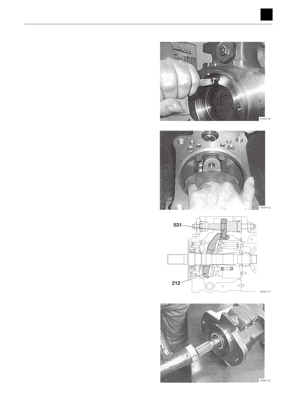
4. Attach the swash plate (212) and the shoe plate
(211) to the support (251).
a. Attach the shoe plate (211) to the swash plate
(212).
b. Attach the bushing of the swash plate to the pin
(531).
• Using your fingers on both hands, check to en-
sure that the swash plate slides smoothly.
• Take care not to damage the sliding surfaces of
the shoe plate.
• Apply grease to sliding surfaces of the swash
plate
(212), support
(251), and shoe plate
(211).
5. Insert the shafts (111) and (127) into the casings
(271) and (272).
6
HYDRAULIC PUMP (MAIN)
4I0AS00
DISASSEMBLY AND ASSEMBLY
4
HYDRAULIC PUMP (MAIN)
6. Attach the cover (261) to the casing (271).
• The cover can be attached as is without grease
applied as there is grease on the oil seal (774) in-
side the cover.
• Take care not to damage the inner oil seal when
attaching the cover.
Cap screw: 21 N·m
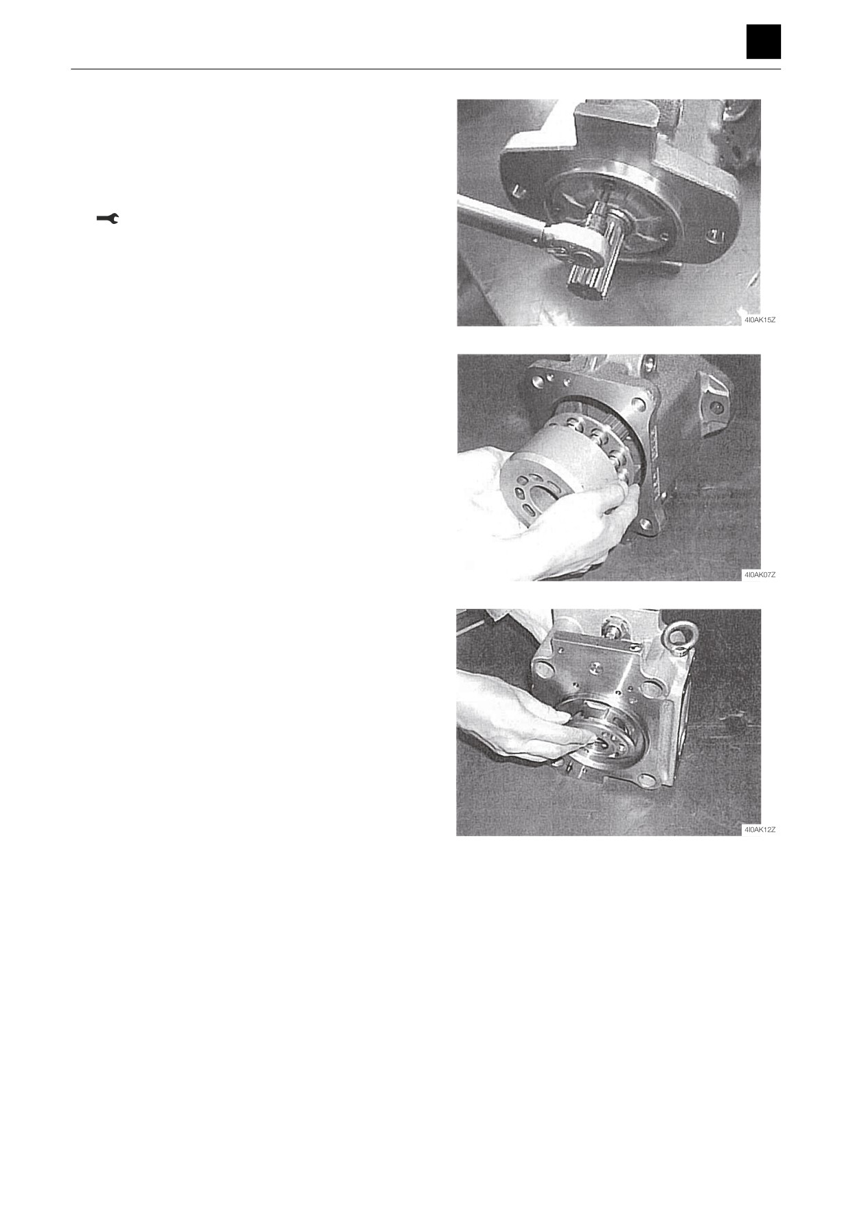
7. Insert the piston (151), shoe (152), plate (153), bush-
ing (156), and spring (157) into the cylinder block
(141). (Cylinder block assembly.)
8. Slide the cylinder block assembly and guide (156)
onto the shaft (111), and insert the resultant assem-
bly into the casing.
9. Line up the valve plates (313) and (314) with the
spring pin (886) and insert them into the block (312).
• Take care not to confuse the intake and exhaust
directions on the valve plates.
7
HYDRAULIC PUMP (MAIN)
4I0AS00