Takeuchi Hydraulic excavator TB1140 (Serial No. 514400002~). Operator's Manual - page 4
DISASSEMBLY AND ASSEMBLY
4
SERVICE STANDARDS
SERVICE STANDARDS
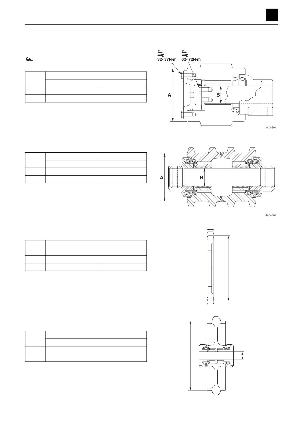
Carrier roller
Loctite #262
Unit: mm (in.)
Criteria
Code
Standard dimension
Allowable value
A
120 (4.7)
-
B
40 (1.6)
-
Track roller
Unit: mm (in.)
Criteria
Code
Standard dimension
Allowable value
A
130 (5.1)
124 (4.9)
B
50 (2.0)
-
Sprocket
B
Unit: mm (in.)
Criteria
Code
Standard dimension
Allowable value
A
530.6
(20.9)
524.6
(20.7)
B
61 (2.4)
55 (2.5)
A
4A0AF03Z
Idler
Unit: mm (in.)
Criteria
Code
Standard dimension
Allowable value
A
454 (17.9)
448 (2.8)
A
B
B
65 (2.6)
-
4A0AF04Z
1
SERVICE STANDARDS
4A0AS00
DISASSEMBLY AND ASSEMBLY
4
SERVICE STANDARDS
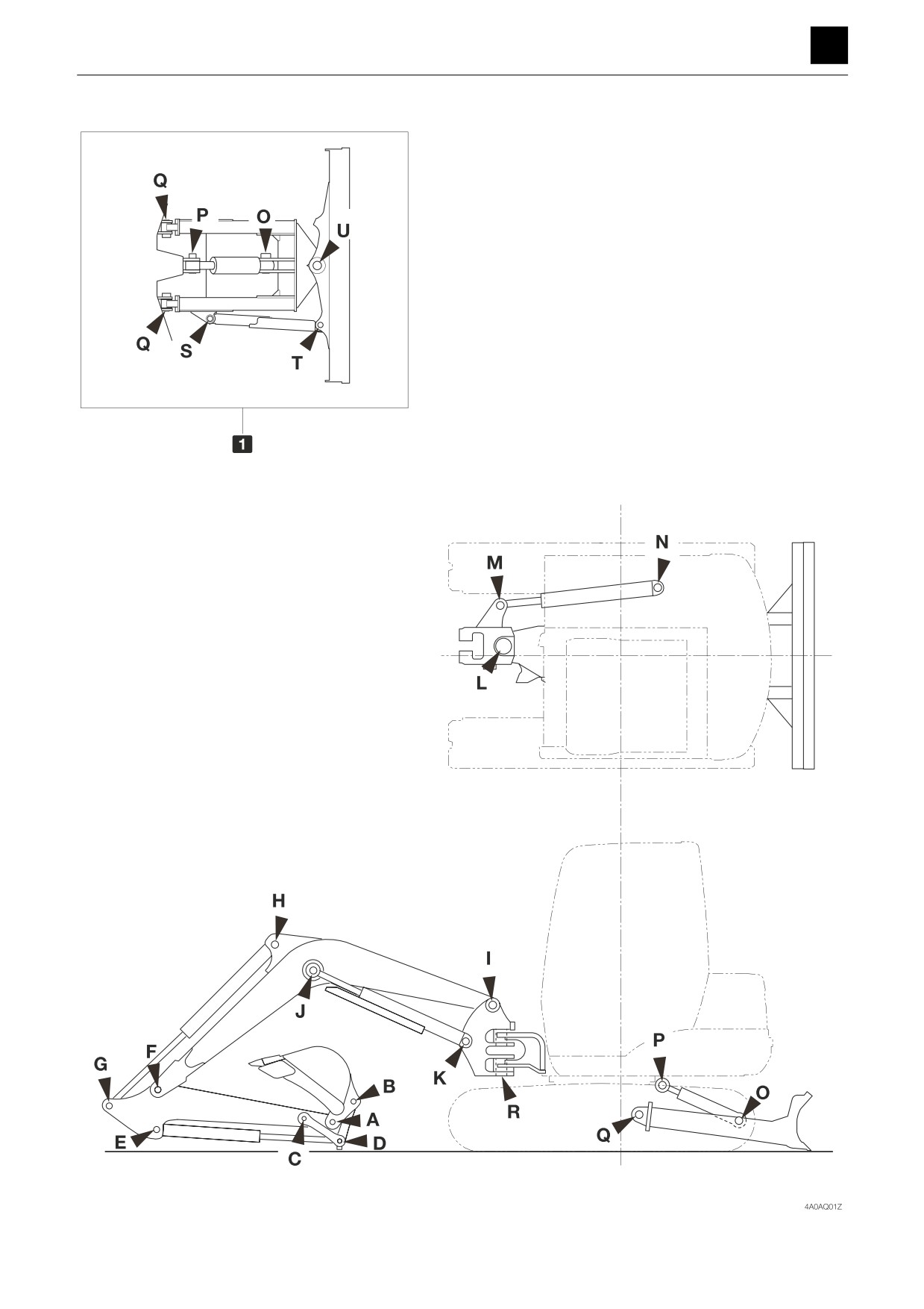
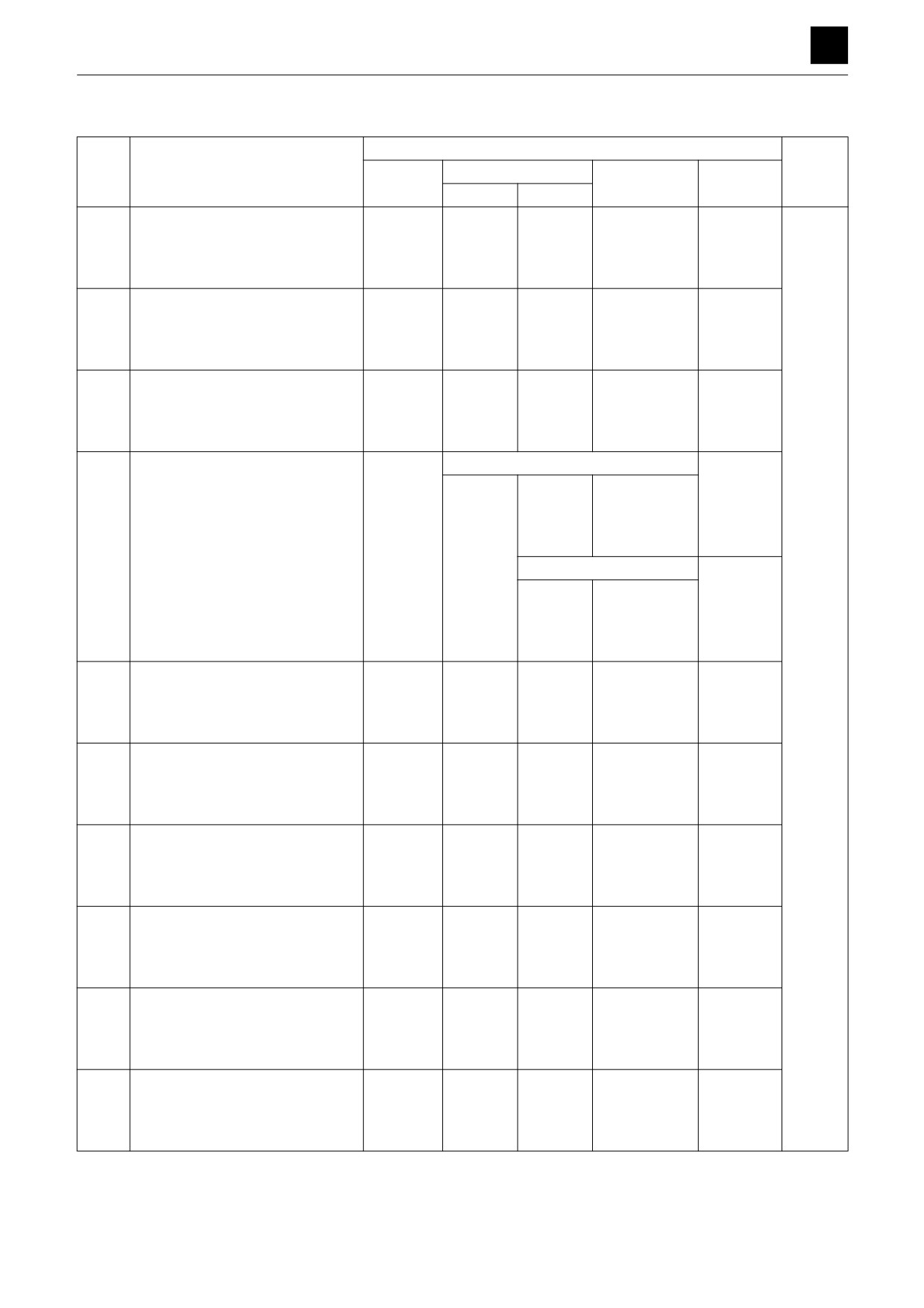
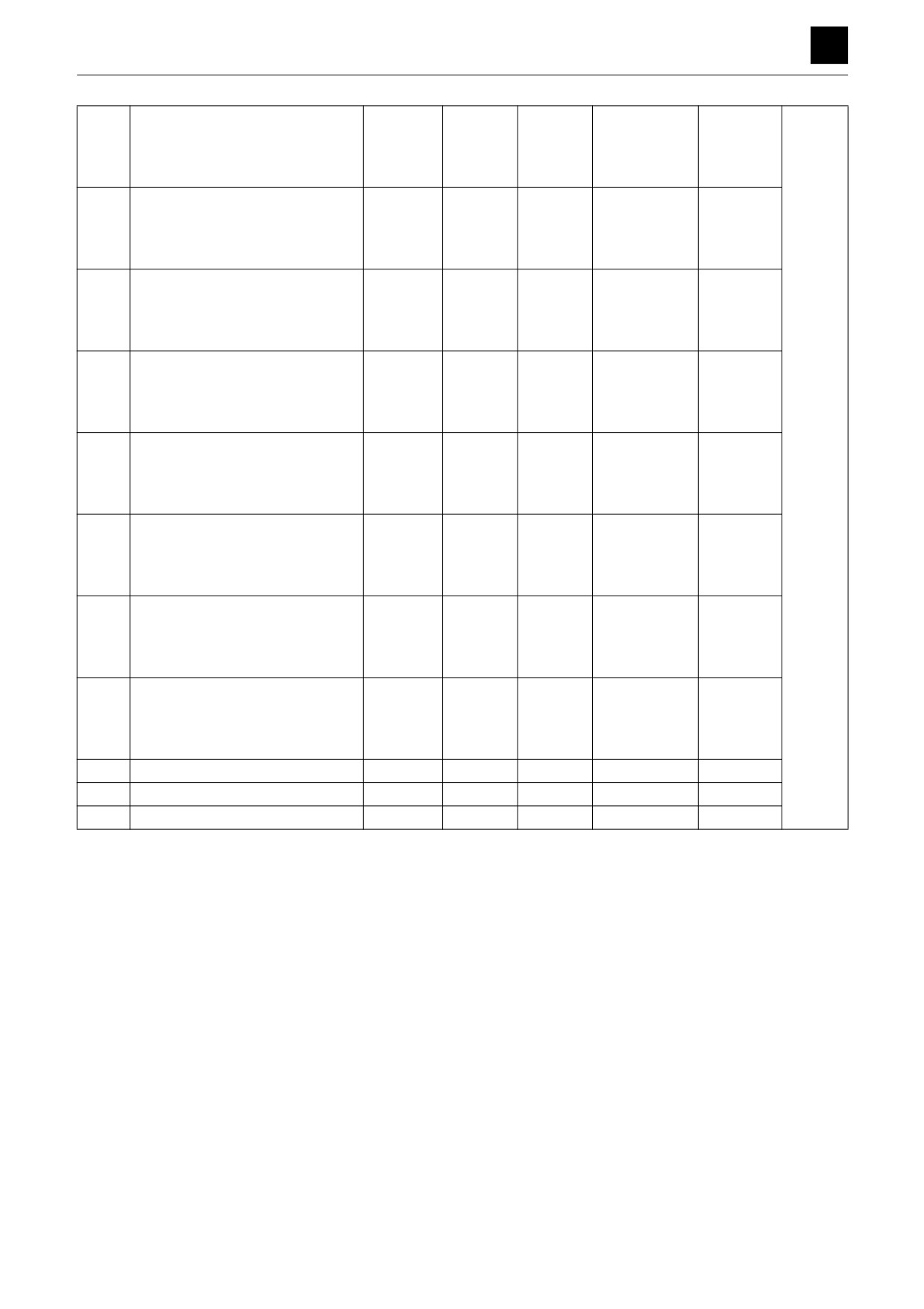
Clearance for pin and bushing
2
SERVICE STANDARDS
4A0AS00
DISASSEMBLY AND ASSEMBLY
4
SERVICE STANDARDS
Unit: mm (in.)
Criteria
Code
Item
Standard
Allowable value
Standard
Allowable
Action
dimension
Axis
Hole
clearance
clearance
-0.02
+0.19
0.16 to 0.24
65
(-0.0008)
(+0.0075)
1
A
Bucket and arm
(0.0063 to
(2.5591)
-0.05
+0.14
(0.04)
0.0095)
(-0.0020)
(+0.0055)
-0.02
+0.19
0.16 to 0.24
65
(-0.0008)
(+0.0075)
1
B
Bucket and link
(0.0063 to
(2.5591)
-0.05
+0.14
(0.04)
0.0095)
(-0.0020)
(+0.0055)
-0.02
+0.19
0.16 to 0.24
65
(-0.0008)
(+0.0075)
1
C
Arm and link
(0.0063 to
(2.5591)
-0.05
+0.14
(0.04)
0.0095)
(-0.0020)
(+0.0055)
Link side
+0.19
0.16 to 0.24
1
(+0.0075)
(0.0063 to
(0.04)
+0.14
-0.02
0.0095)
65
(+0.0055)
D
Bucket cylinder and link
(-0.0008)
(2.5591)
Cylinder side
-0.05
+0.25
(-0.0020)
0.07 to 0.30
1
(+0.0098)
(0.0028 to
(0.04)
+0.05
0.0118)
(+0.0020)
-0.02
+0.25
Replace
0.07 to 0.30
65
(-0.0008)
(+0.0098)
1
E
Bucket cylinder and arm
(0.0028 to
(2.5591)
-0.05
+0.05
(0.04)
0.0118)
(-0.0020)
(+0.0020)
-0.02
+0.19
0.16 to 0.24
75
(-0.0008)
(+0.0075)
1
F
Arm and boom
(0.0063 to
(2.9528)
-0.05
+0.14
(0.04)
0.0095)
(-0.0020)
(+0.0055)
-0.02
+0.25
0.07 to 0.30
80
(-0.0008)
(+0.0098)
1
G
Arm cylinder and arm
(0.0028 to
(3.1496)
-0.05
+0.05
(0.04)
0.0118)
(-0.0020)
(+0.0020)
-0.02
+0.25
0.07 to 0.30
80
(-0.0008)
(+0.0098)
H
Arm cylinder and boom
(0.0028 to
1 (0.04)
(3.1496)
-0.05
+0.05
0.0118)
(-0.0020)
(+0.0020)
-0.02
+0.31
0.08 to 0.36
75
(-0.0008)
(+0.0122)
I
Boom and swing bracket
(0.0031 to
1 (0.04)
(2.9528)
-0.05
+0.26
0.0142)
(-0.0020)
(+0.0102)
-0.02
+0.25
0.07 to 0.30
75
(-0.0008)
(+0.0098)
J
Boom cylinder and boom
(0.0028 to
1 (0.04)
(2.9528)
-0.05
+0.05
0.0118)
(-0.0020)
(+0.0020)
3
SERVICE STANDARDS
4A0AS00
DISASSEMBLY AND ASSEMBLY
4
SERVICE STANDARDS
-0.02
+0.25
0.07 to 0.30
75
(-0.0008)
(+0.0098)
K
Boom cylinder and swing bracket
(0.0028 to
1 (0.04)
(2.9528)
-0.05
+0.05
0.0118)
(-0.0020)
(+0.0020)
-0.02
+0.17
0.17 to 0.22
140
(-0.0008)
(+0.0067)
L
Swing bracket and turntable
(0.0067 to
1 (0.04)
(5.5118)
-0.05
+0.15
0.0087)
(-0.0020)
(+0.0059)
-0.02
+0.25
0.07 to 0.30
100
(-0.0008)
(+0.0098)
M
Swing cylinder and swing bracket
(0.0028 to
1 (0.04)
(3.9370)
-0.05
+0.05
0.0118)
(-0.0020)
(+0.0020)
-0.02
+0.25
0.07 to 0.30
100
(-0.0008)
(+0.0098)
N
Swing cylinder and turntable
(0.0028 to
1 (0.04)
(3.9370)
-0.05
+0.05
0.0118)
(-0.0020)
(+0.0020)
-0.02
+0.25
0.07 to 0.30
70
(-0.0008)
(+0.0098)
Replace
O
Blade cylinder and blade
(0.0028 to
1 (0.04)
(2.7559)
-0.05
+0.05
0.0118)
(-0.0020)
(+0.0020)
-0.02
+0.25
0.07 to 0.30
70
(-0.0008)
(+0.0098)
P
Blade cylinder and lower frame
(0.0028 to
1 (0.04)
(2.7559)
-0.05
+0.05
0.0118)
(-0.0020)
(+0.0020)
-0.02
+0.19
0.16 to 0.24
70
(-0.0008)
(+0.0075)
Q
Blade and lower frame
(0.0063 to
1 (0.04)
(2.7559)
-0.05
+0.14
0.0095)
(-0.0020)
(+0.0055)
-0.02
+0.17
0.17 to 0.22
140
(-0.0008)
(+0.0067)
R
Swing bracket and turntable
(0.0067 to
1 (0.04)
(5.5118)
-0.05
+0.15
0.0087)
(-0.0020)
(+0.0059)
S
Angle cylinder and blade arm
-
-
-
-
-
T
Angle cylinder and blade
-
-
-
-
-
U
Blade arm and blade
-
-
-
-
-
4
SERVICE STANDARDS
4A0AS00
DISASSEMBLY AND ASSEMBLY
4
DRIVE SYSTEM
DRIVE SYSTEM
Engine
Construction
Z
OUT
IN
X
Z
X
Y
Y
ThreeBond #1324
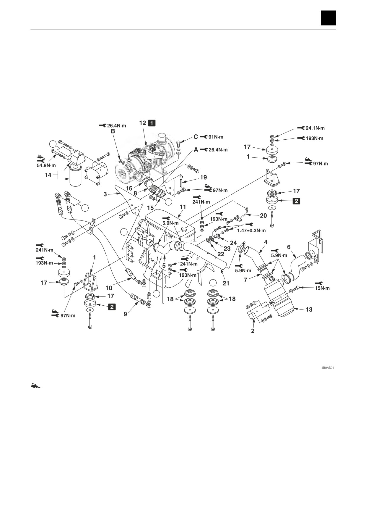
1 Affix in the order of part A, part B,
1. Engine hood
9. Hose
17. Cushion rubber
and then part C.
2. Bracket
10. Hose
18. Cushion rubber
2 “A” die stamp
3. Bracket
11. Engine
19. Hose
4. Hose
12. DPD assembly
20. Earth ground cable
5. Hose
13. Air cleaner
21. Pipe
6. Hose
14. Oil filter
22. Gasket
7. Pipe
15. Gasket
23. Adapter
8. Pipe
16. Gasket
24. Air flow sensor
1
DRIVE SYSTEM
4B0AS00
DISASSEMBLY AND ASSEMBLY
4
DRIVE SYSTEM
Removing the engine
1. Remove the battery ground cable (34) from the bat-
tery terminal.
2. Remove the engine hood, the side covers Right and
Left, and the engine cover (Front).
“Removing the covers”
3. Remove the counterweight.
“Removing the upper structure”
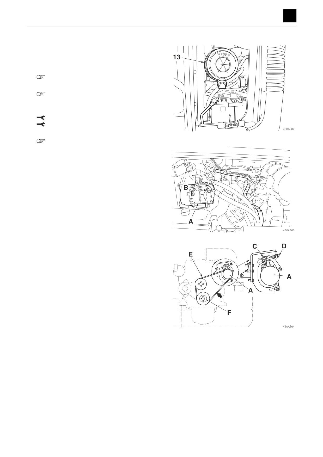
4. Disconnect the electrical wiring to the air cleaner
(13), and remove the air cleaner (13).
Bolt: 15 N·m (11.1 ft.-lb)
Band: 5.9 N·m (4.4 ft.-lb)
5. Remove the radiator assembly.
“Removing the radiator"
6. Remove the compressor (A).
• Do not loosen the hoses (B) as refrigerant gas
may be released from the hoses if they are loos-
ened.
a. Loosen the nut (C).
b. Loosen the bolt (D), and release the tension in the
V belt (E).
• Apply a force of 98 N (22 lbf) to the midpoint
between the pulley (F) and compressor (A) dur-
ing assembly to make the belt slacken by 8 mm
(0.3 in.). Alternatively, tighten the belt to a ten-
sion of 529 N (119 lbf) measured using a ten-
sion gauge.
• Use the bolt (D) to make adjustments.
c. Take out all bolts used to secure the compressor
in place, and remove the compressor.
• When removing the engine, place it in a loca-
tion where it is out of the way.
2
DRIVE SYSTEM
4B0AS00
DISASSEMBLY AND ASSEMBLY
4
DRIVE SYSTEM
7. Disconnect the battery cable and the engine electri-
cal wiring on the engine side.
• Attach identification labels to each of the wires.
8. Disconnect the engine ground cable (20).
9. Disconnect the hoses (9) and (10).
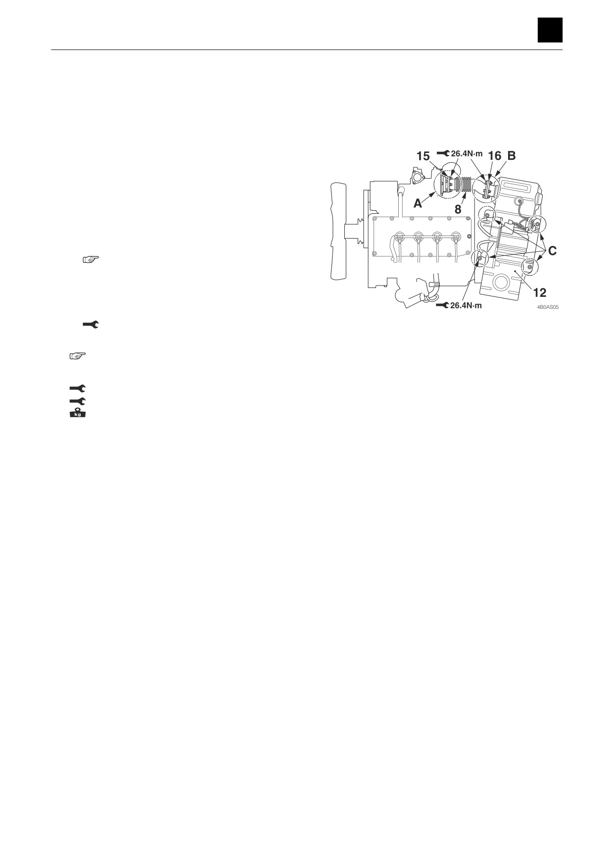
10. Remove the DPD assembly (12).
a. Disconnect the electrical wiring to the DPD on the
DPD side.
• Attach identification labels to each of the wires.
b. Take out the part A, part B, and part C nuts, and
remove the DPD assembly (12).
• Disassembly, assembly, and inspection of the
DPD assembly
“Engine Workshop Manual”
• During assembly, take out the gasket (16), and
replace it with a new one.
• During assembly, affix the parts in the order of
part A, part B, and then part C.
Nut: 26.4 N·m (19.5 ft.-lb)
11. Remove the hydraulic pump.
“Removing the hydraulic pump”
12. Take out the nuts, and suspend the engine.
Nut top: 241 N·m (177.8 ft.-lb)
Nut bottom: 193 N·m (142.4 ft.-lb)
: 333 kg (737.4 lb)
Installing the engine
To install the engine, follow the same procedures as for
removal but in the reverse order.
3
DRIVE SYSTEM
4B0AS00
DISASSEMBLY AND ASSEMBLY
4
DRIVE SYSTEM
Radiator
Construction
a
X
a
X
Y
Y
ThreeBond #1324
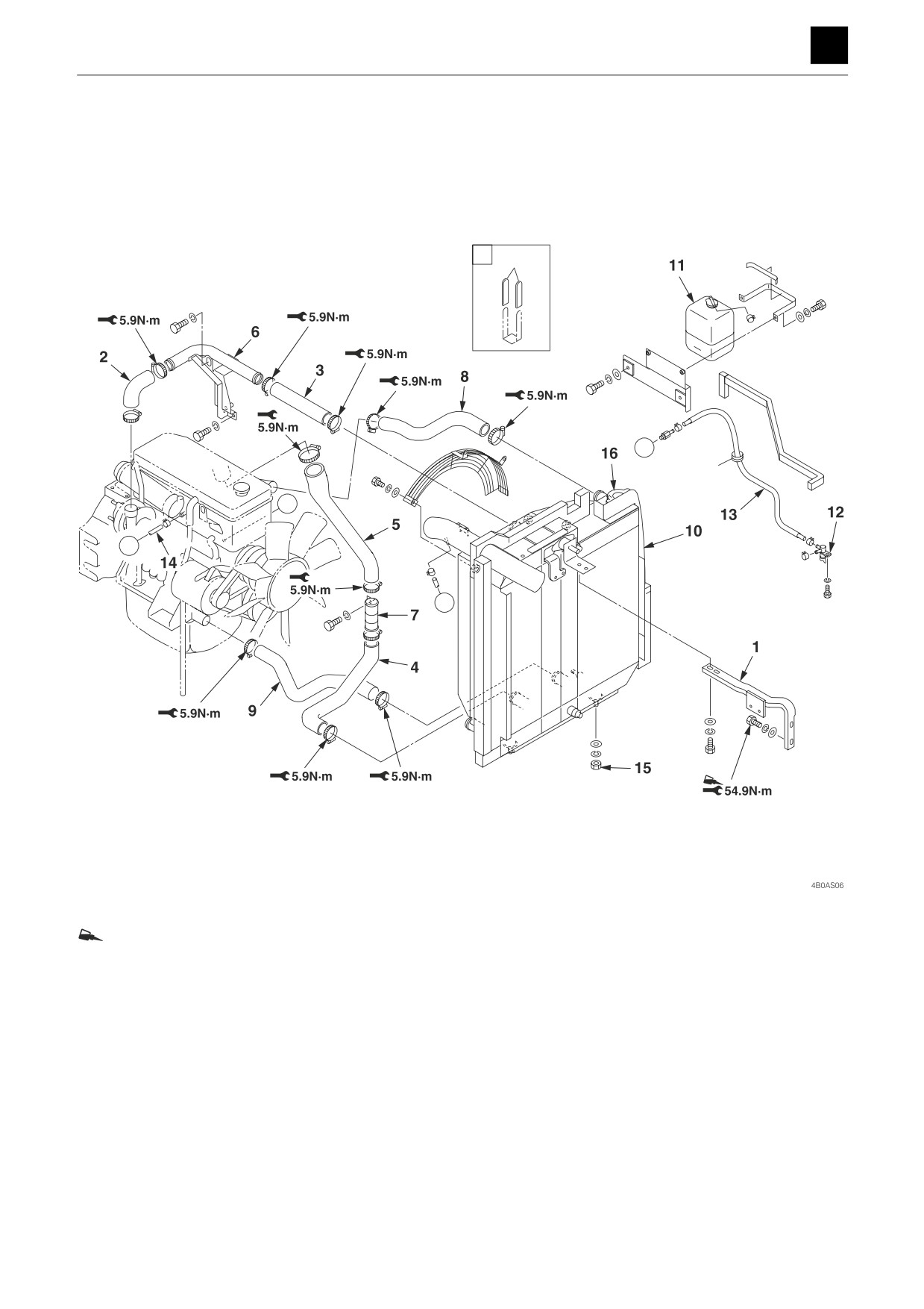
1. Bracket
9. Hose
2. Hose
10. Radiator assembly
3. Hose
11. Sub-tank
4. Hose
12. Drain valve
5. Hose
13. Hose
6. Pipe
14. Hose
7. Pipe
15. Nut
8. Hose
4
DRIVE SYSTEM
4B0AS00
DISASSEMBLY AND ASSEMBLY
4
DRIVE SYSTEM
Removing the radiator
1. Remove the engine hood, the side covers Right and
Left, and the engine cover (Front).
“Removing the covers”
2. Drain the hydraulic oil from the tank.
“Removing the hydraulic tank”
3. Remove the counterweight.
“Removing the upper structure”
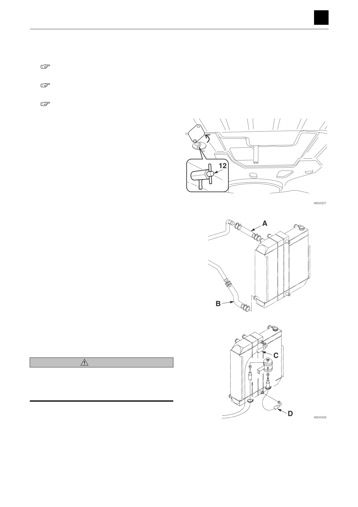
4. Place a receptacle under the drain valve (12), and
drain the coolant out into this receptacle.
• Total coolant volume: 18.5 L (19.5 US qt.)
5. Disconnect the hoses (A) and (B).
6. Remove the hoses (3), (4), (8), and (9).
4B0AS08
7. Disconnect the hoses (C) and (D).
• Place caps on the ends of the disconnected hos-
es.
WARNING
• Drain out the coolant when disconnecting the hoses.
• Read the repair manual for the air conditioner and fol-
low the instructions contained therein when working on
the air conditioner.
5
DRIVE SYSTEM
4B0AS00
DISASSEMBLY AND ASSEMBLY
4
DRIVE SYSTEM
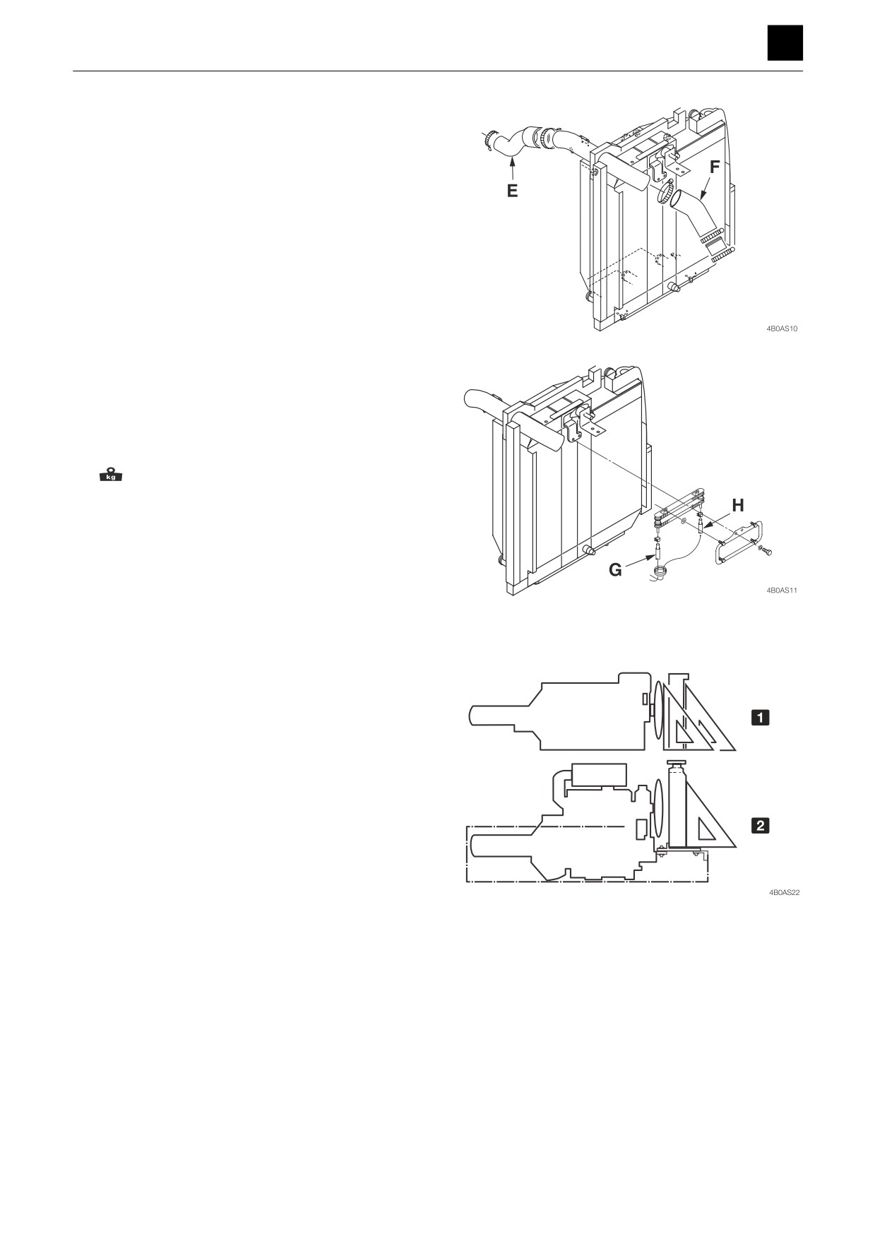
8. Disconnect the hoses (E) and (F).
9. Disconnect the hoses (G) and (H).
10. Take out the nut (15), and remove the radiator as-
sembly.
• Slowly raise the radiator assembly using a hoist
being careful not to bump it on the fan.
Radiator assembly: 81 kg (180 lb)
Installing the radiator
To install the radiator, follow the same procedures as for
removal but in the reverse order.
The radiator must be mounted at a right angle to the
frame and parallel to the cooling fan.
Adjust the position to ensure that there is a clearance of
17.5 mm (0.689 in.) for the fan and shroud.
1 To be mounted parallel thereto
2 To be mounted at a right angle thereto
6
DRIVE SYSTEM
4B0AS00
DISASSEMBLY AND ASSEMBLY
4
DRIVE SYSTEM
Hydraulic pump
Construction
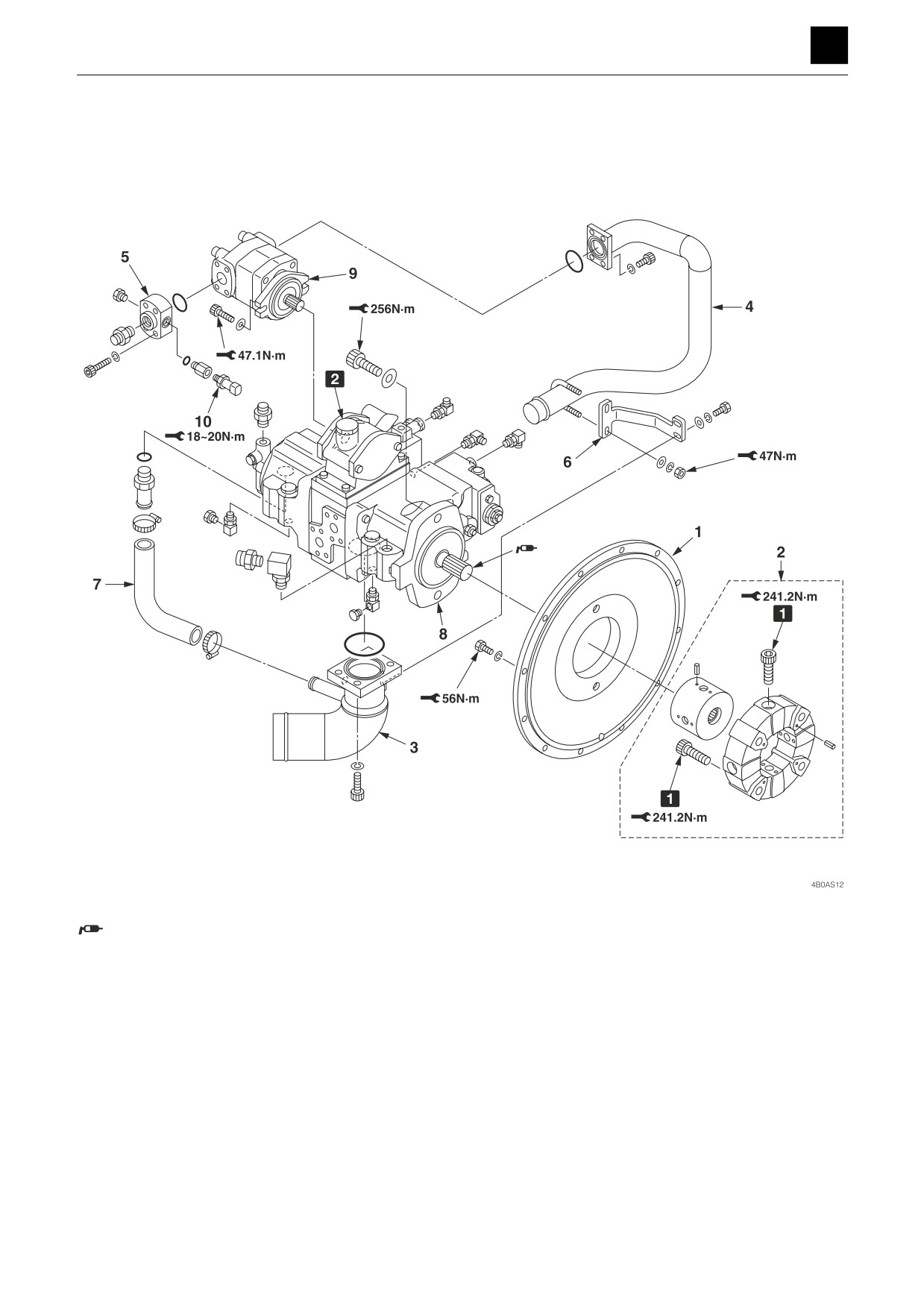
Apply molybdenum disulfide grease to the spline.
• Applying a large amount of grease on the spline
hole in the coupling assembly may cause the
grease to drip down onto rubber parts, which could
cause the rubber to deteriorate.
1 The bolts have already been coated with a special coat-
1. Engine housing
6. Stay
ing to prevent them from becoming loose. Do not use
2. Coupling assembly
7. Suction hose
bolts other than the ones that came with the machine.
3. Suction pipe
8. Main pump
Do not reuse bolts that have been loosened.
4. Flange pipe
9. Gear pump
2 Air vent port
5. Flange nipple
10. Pressure transmitter
7
DRIVE SYSTEM
4B0AS00
DISASSEMBLY AND ASSEMBLY
4
DRIVE SYSTEM
Removing the hydraulic pump
1. Remove the battery ground cable from the battery
terminal.
2. Remove the engine hood, the side covers Right and
Left, and the engine cover (Front).
“Removing the covers”
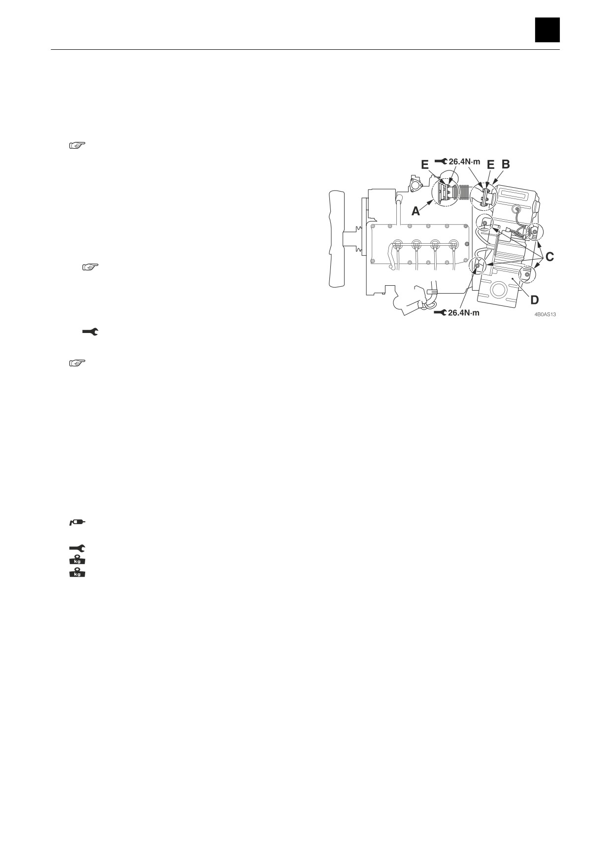
3. Remove the DPD.
a. Disconnect the electrical wiring to the DPD on the
DPD side.
• Attach identification labels to each of the wires.
b. Take out the part A, part B, and part C nuts, and
remove the DPD assembly (D).
• Disassembly, assembly, and inspection of the
DPD assembly
“Engine Workshop Manual”
• During assembly, take out the gasket (E), and
replace it with a new one.
• During assembly, affix the parts in the order of
part A, part B, and then part C.
Nut: 26.4 N·m (19.5 ft.-lb)
4. Drain the hydraulic oil from the tank.
“Removing the hydraulic tank”
5. Disconnect the electrical wiring from the hydraulic
pump.
6. Disconnect the suction hoses from the hydraulic
pump.
7. Disconnect the discharge hoses from the hydraulic
pump.
8. Remove the filters.
9. Take out the bolts, and remove the hydraulic pump
assembly.
Apply molybdenum disulfide grease to the
spline.
Bolt: 256 N·m (189 ft.-lb)
Main pump: 87 kg (192 lb)
Gear pump: 5.4 kg (11.9 lb)
8
DRIVE SYSTEM
4B0AS00
DISASSEMBLY AND ASSEMBLY
4
DRIVE SYSTEM
Installing the hydraulic pump
To install, follow the same procedures as for removal but
in the reverse order.
Cautions on starting the hydraulic pump
a. Fill the pump housing with hydraulic oil before start-
ing.
• Fill the pump housing with hydraulic oil from the
air vent port “2.”
b. Start the engine, let it run at a low idling speed for
ten minutes, and then extend and retract each cyl-
inder 4 or 5 times, without letting any reach the
stroke end.
c. Run the engine at high speed and then extend and
retract each cylinder 4 or 5 times, without letting
any reach the stroke end.
d. Return the engine speed to low idle and then ex-
tend and retract each cylinder 4 or 5 times, without
letting any reach the stroke end.
9
DRIVE SYSTEM
4B0AS00
DISASSEMBLY AND ASSEMBLY
4
DRIVE SYSTEM
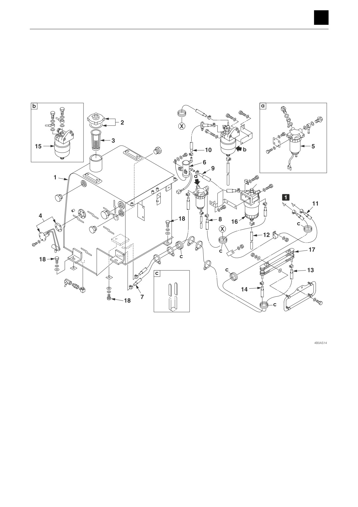
Fuel tank
Construction
1 To engine
1. Fuel tank
10. uel hose
2. Cap
11. Fuel hose
3. Strainer
12. Fuel hose
4. Fuel sender
13. Fuel hose
5. Sedimenter
14. Fuel hose
6. Fuel pump
15. Fuel filter
7. Fuel hose
16. Fuel filter
8. Fuel hose
17. Fuel cooler
9. Fuel hose
18. Bolt
10
DRIVE SYSTEM
4B0AS00
DISASSEMBLY AND ASSEMBLY
4
DRIVE SYSTEM
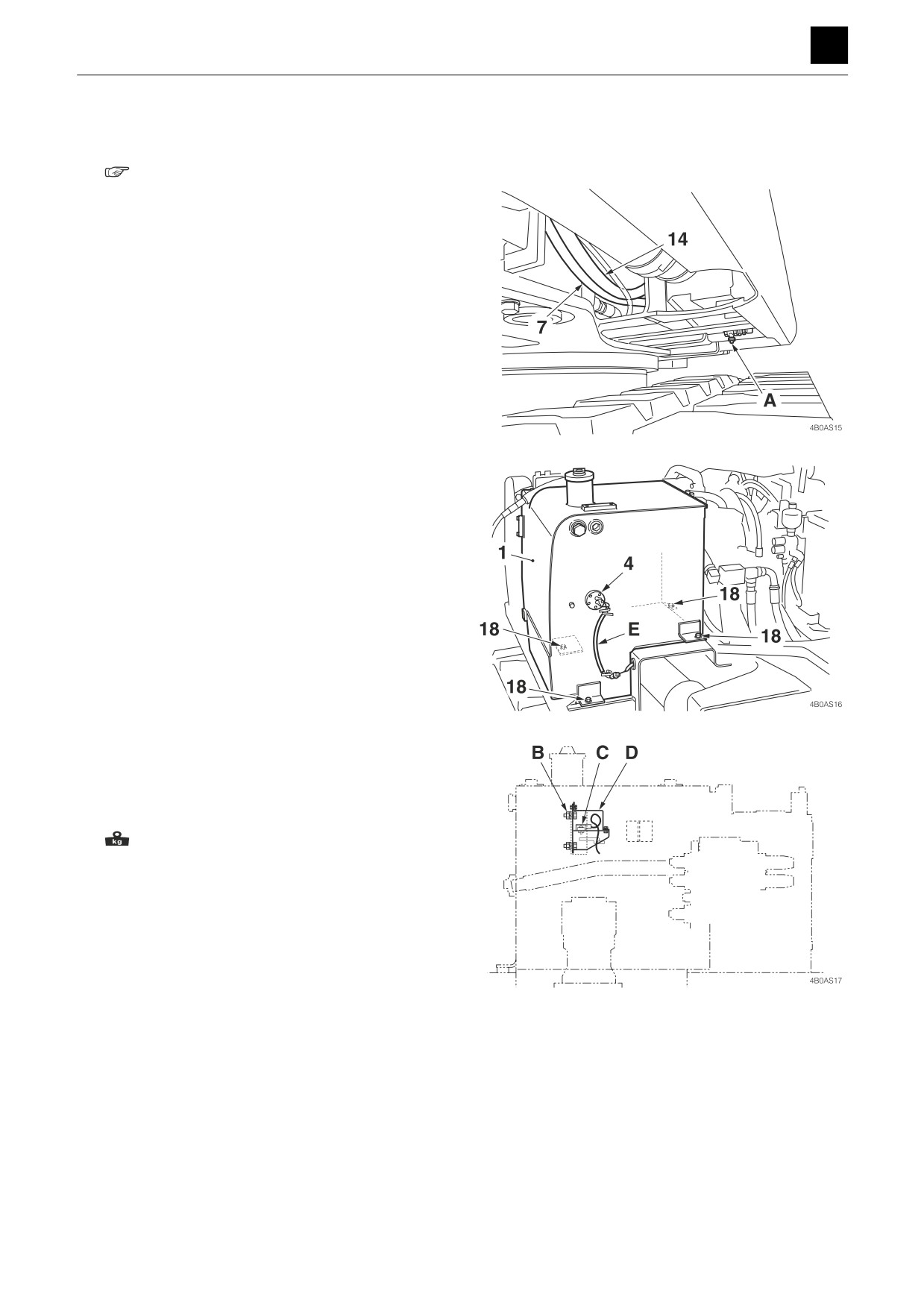
Removing the fuel tank
1. Remove the covers from the perimeter around the
tank.
“Removing the covers”
2. Loosen the drain valve (A), and let the fuel drain out.
• Fuel tank capacity: 250 L (66.0 US gal.)
3. Disconnect the fuel hoses (7) and (14).
4. Take out the nut, and remove the sensor and bracket
from the fuel tank.
5. Disconnect the electrical wiring (E) from the fuel
sender (4).
6. Take out the bolts (18) holding the fuel tank (1) in
place, and suspend the fuel tank (1) and remove it.
: 78 kg (170 lb)
Installing the fuel tank
To install, follow the same procedures as for removal but
in the reverse order.
11
DRIVE SYSTEM
4B0AS00
DISASSEMBLY AND ASSEMBLY
4
DRIVE SYSTEM
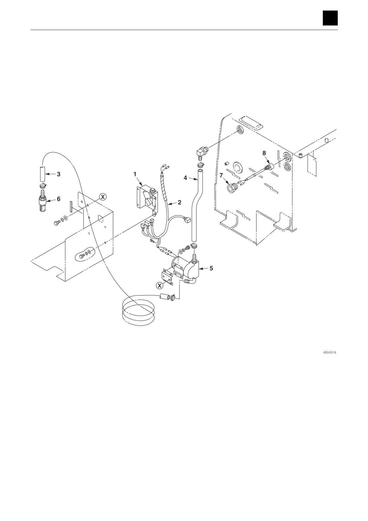
Fuel filler pump
Construction
1. Cover assembly for electronic parts
5. Pump
2. Harness
6. Fuel trailer
3. Hose
7. Plug
4. Hose
8. Level switch
12
DRIVE SYSTEM
4B0AS00
DISASSEMBLY AND ASSEMBLY
4
DRIVE SYSTEM
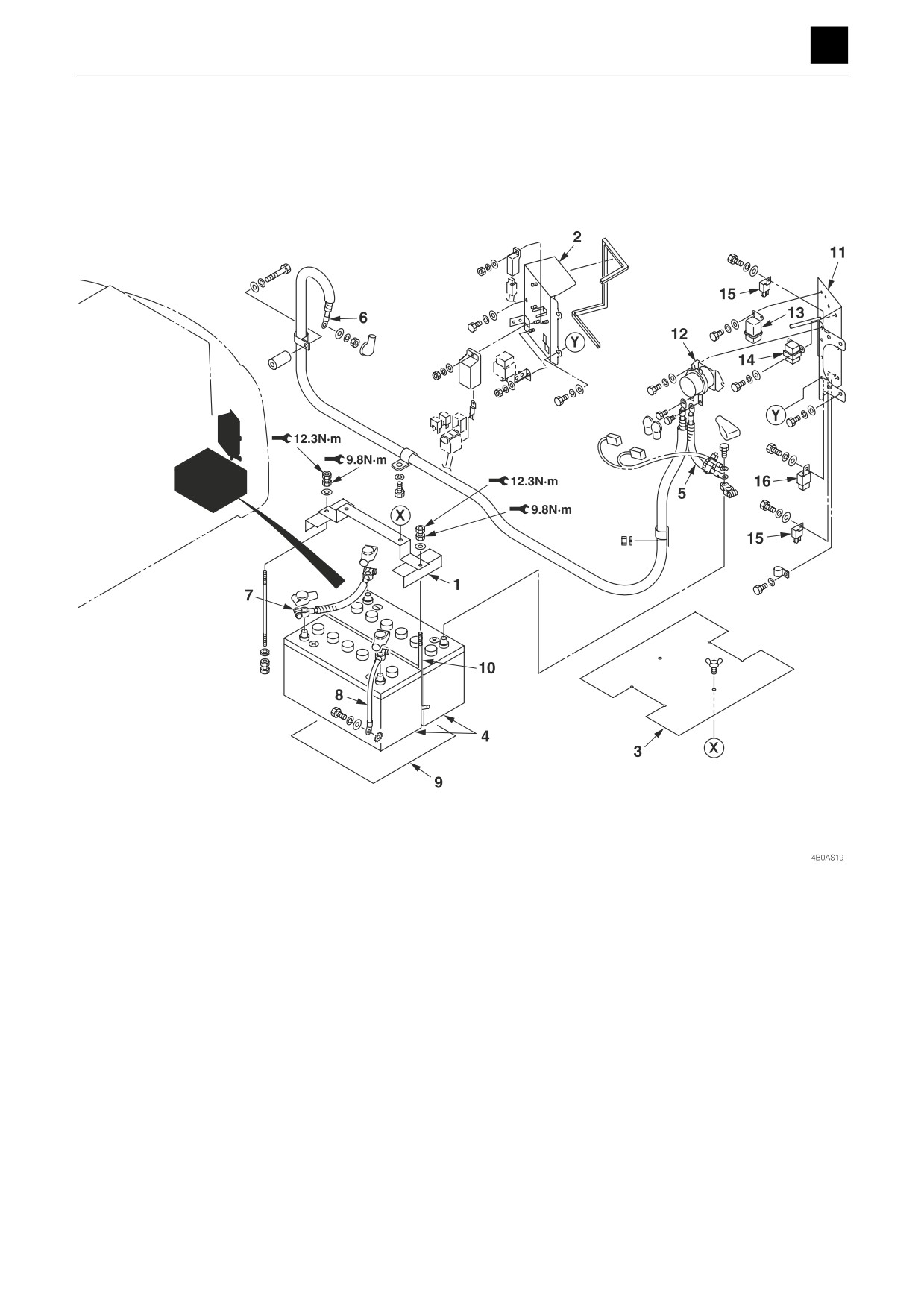
Battery
1. Clamp
9. Rubber seat
2. Cover
10. Hook bolt
3. Seat
11. Bracket
4. Battery
12. Battery relay
5. Relay cable (+)
13. Glow lamp relay
6. Starter cable
14. Starter relay
7. Serial cable
15. Main relay
8. Earth ground cable
16. 24-V diode for the CA relay
13
DRIVE SYSTEM
4B0AS00
DISASSEMBLY AND ASSEMBLY
4
DRIVE SYSTEM
Removing the battery
WARNING
• Wear protective glasses and gloves when working with
batteries.
• Batteries generate flammable hydrogen gas which may
explode. Keep away from flames and sparks.
• Be sure to stop the engine by turning off the starter
switch before inspecting or handling the battery.
• Be careful not to let metal tools (or any metal objects)
such as a hammer or wrench come into contact with the
battery terminals.
• When disconnecting the battery wiring, always discon-
nect it from the earth side (-). When connecting, con-
nect the earth side last.
• Loose battery terminals may cause sparks. Be sure to
fasten terminals tightly.
1. Disconnect the battery ground cable (8) from the
battery terminal.
2. Remove the relay cable (5).
3. Remove the serial cable (7).
4. Remove the nuts.
Nut top: 12.3 N·m (9.1 ft.-lb)
Nut bottom: 9.8 N·m (7.2 ft.-lb)
5. Remove the battery (4).
Installing the battery
To install, follow the same procedures as for removal but
in the reverse order.
14
DRIVE SYSTEM
4B0AS00
DISASSEMBLY AND ASSEMBLY
4
TRAVEL SYSTEM
TRAVEL SYSTEM
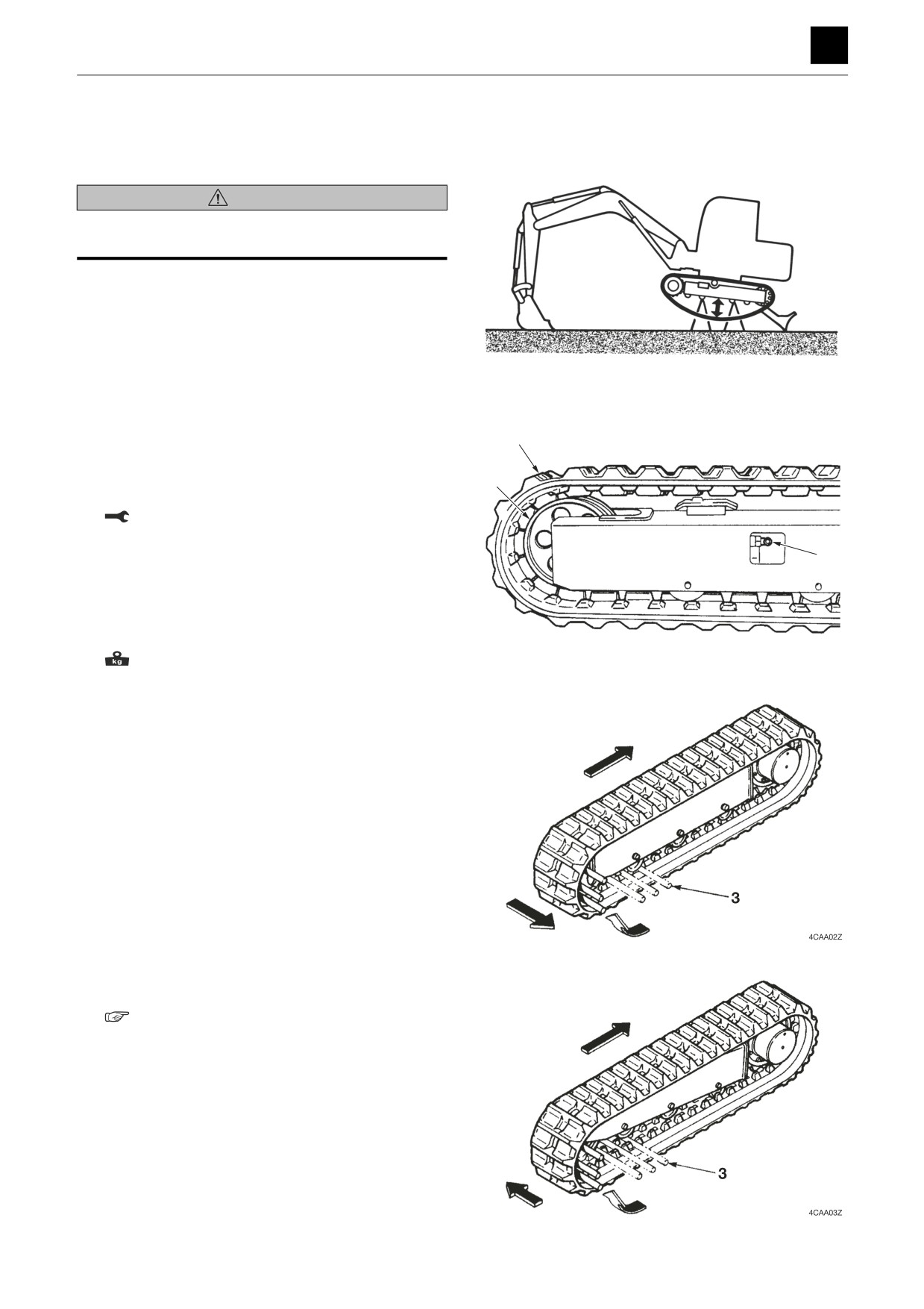
Removing the crawler
WARNING
When working under the machine while it is raised up, be
sure to use a stand to support the machine.
Important: When replacing crawlers, replace both the
right and left ones at the same time.
1. Lift up the machine.
• Use the blade and hoe attachment to raise the
machine.
4C0AQ01Z
2. Loosen the crawler tension for the crawler (1).
• When loosening the check valve (2), do it slowly.
Stop loosening the check valve once grease
1
starts to come out.
If no grease comes out, slightly move the machine
4
forward and backward.
Check valve: 177 N·m (130 ft.-lb)
3. Insert the iron pipe (3) into the crawler and then ro-
2
tate the sprocket in the reverse direction.
4. Stop rotating the sprocket once the pipe reaches the
side of the idler.
5. Slide the crawler over to the side and remove it.
Crawler: 752 kg (1658 lb)
4C0AF01Z
Installing the crawler
1. Lift up the machine, and insert the crawler into the
frame.
• Set the crawler so that it is engaged with the
sprocket.
2. Insert the iron pipe (3) into the crawler and then ro-
tate the sprocket in the reverse direction.
3. Stop rotating the sprocket once the pipe (3) reaches
the side of the sprocket.
4. Slide the crawler into a position where it can be prop-
erly fitted to engage with the idler.
5. Position the crawler so as to ensure that it is securely
engaged with the sprocket and idler and then adjust
the crawler tension.
“2. Service data, Performance criteria”
1
TRAVEL SYSTEM
4C0AS00
DISASSEMBLY AND ASSEMBLY
4
TRAVEL SYSTEM
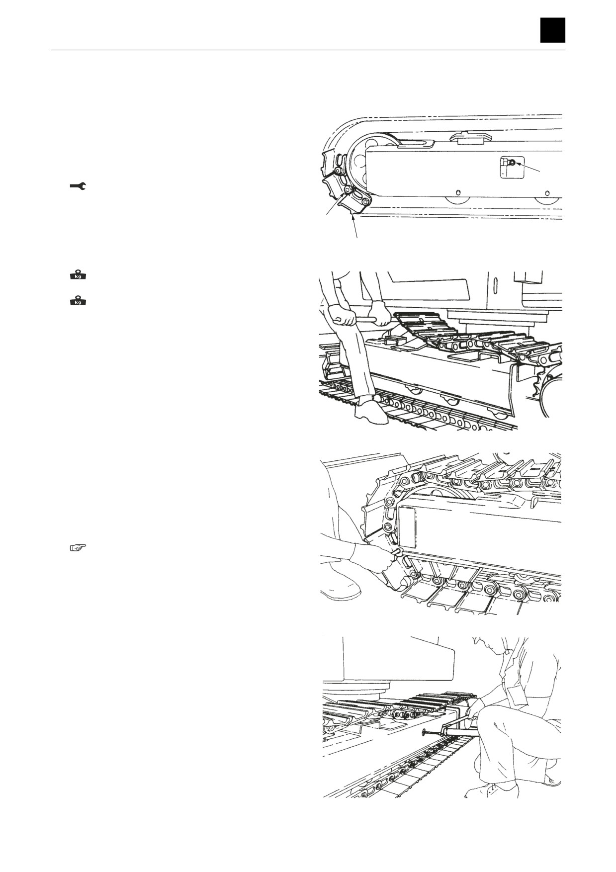
Removing a steel crawler or segmented rubber crawler
1. Stop the machine at a position at which the master
pin is located at the front of the idler.
2. Loosen the crawler tension of the crawler (1).
• Proceed slowly when loosening the check valve
(2) and stop once grease starts to come out. If no
grease comes out, slightly move the machine for-
ward and backward.
2
Check valve: 177 N·m (130 ft.-lb)
3. Take out the master pin (3), and disconnect the
crawler (1).
3
4. Use the blade and hoe attachment to raise the ma-
1
4C0AF02Z
chine and then let the travel motor run at slow speed
in the reverse direction to unwind the crawler.
Steel crawler
(500-mm-wide model): 750 kg
(1654 lb)
Segmented rubber crawler: 812kg (1790 lb)
Installing a steel crawler or segmented rubber
crawler
1. Use the blade and hoe attachment to lift up the ma-
chine and then position the crawler onto the bottom
of the frame.
• Be careful not to install the crawler in the wrong di-
rection.
4C0AF03Z
2. Fit the links into the sprockets and then let the travel
motor run at slow speed in the forward direction to
wind the crawler onto the sprockets.
3. Lower the machine and insert the master pin to se-
cure the crawler in place.
• Line up the pin holes, and insert a temporary pin.
4. Lift up the machine, and adjust the crawler tension.
• Check the crawler tension.
“2. Service data, Performance criteria”
4C0AF04Z
4C0AF05Z
2
TRAVEL SYSTEM
4C0AS00
DISASSEMBLY AND ASSEMBLY
4
TRAVEL SYSTEM
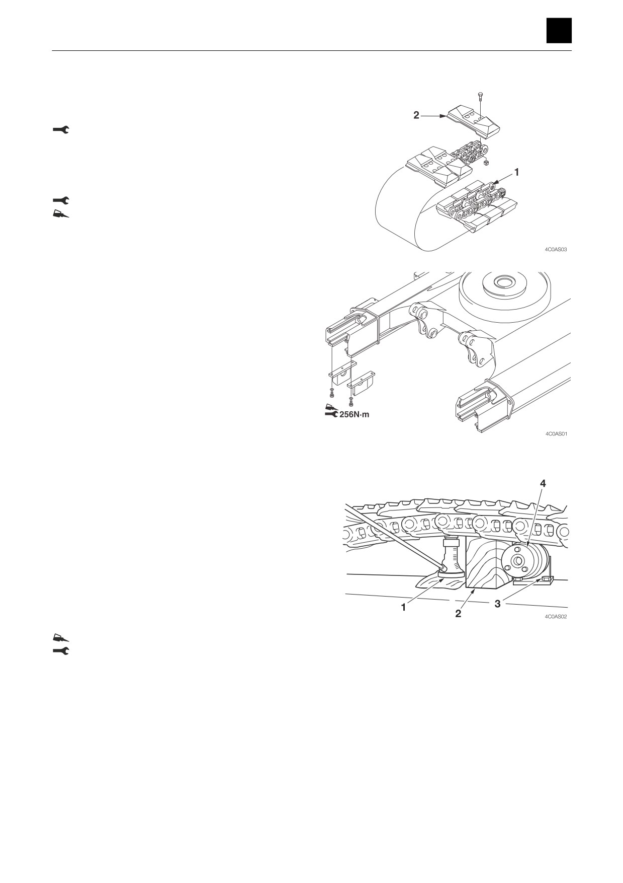
Attaching/removing a segmented rubber crawler
The link assembly (1) is to be installed and removed in
the same way as for the steel crawler.
Insert the rubber pad (2) at the torque listed below.
Nut: 412 N·m (304 ft.-lb)
Replacing the crawler
Attach the shoe guide if replacing a rubber crawler with
a steel crawler.
Bolt: 256 N·m (189 ft.-lb)
ThreeBond #1324 or its equivalent
Removing the carrier roller
1. Loosen the crawler belt tension.
2. Use the hydraulic jack (1) to push up the crawler belt.
• Insert the stopper (2) to prevent the crawler belt
from popping out from the hydraulic jack (1) and
falling.
3. Loosen the nut (3), take out the bolt, and remove the
roller (4).
Installing the carrier roller
To install, follow the same procedures as for removal but
in the reverse order.
Bolt: ThreeBond #1324
Bolt: 256 N·m (189 ft.-lb)
3
TRAVEL SYSTEM
4C0AS00
DISASSEMBLY AND ASSEMBLY
4
TRAVEL SYSTEM
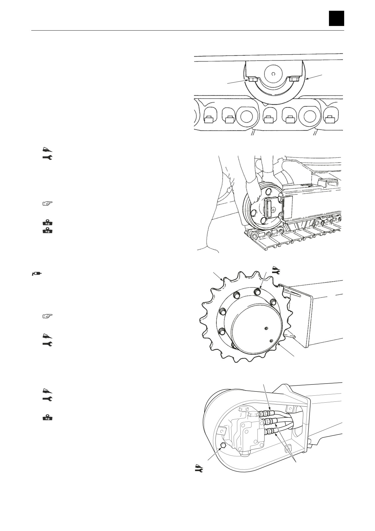
Removing the track roller
1. Loosen the crawler tension.
2. Loosen the roller bolt (1) slightly (about one turn).
2
3. Lift up the machine, take out the bolt (1), and remove
1
the roller (2).
Installing the track roller
1. Temporarily secure the roller (2) in place by tighten-
ing down the bolt (1).
2. Lower the machine to the ground and then further
tighten down the bolt.
4C0AH03Z
Bolt: ThreeBond #1324
Bolt: 299 N·m (221 ft.-lb)
3. Lift up the machine, and adjust the crawler tension.
Removing the idler and track adjuster
1. Remove the crawler.
“Removing the crawler"
2. Pull out the idler and the track adjuster.
Idler: 103 kg (227 lb)
Track adjuster: 97 kg (214 lb)
Installing the idler and track adjuster
4C0AF09Z
To install, follow the same procedures as for removal but
in the reverse order.
2
1
Apply on the sliding surfaces of the track adjuster
182N·m
piston and cylinder.
Removing the travel motor
1. Remove the crawler.
“Removing the crawler"
2. Take out the bolts (1), and remove the sprocket (2).
Bolt: ThreeBond #1324
Bolt: 281 N·m (207 ft.-lb)
3. Remove the cover, and disconnect the hydraulic
3
hoses (4).
4C0AQ07Z
4. Suspend the travel motor (3) temporarily, and re-
move the bolts (5).
4
Bolt: ThreeBond #1324
Bolt: 281 N·m (207 ft.-lb)
5. Raise the travel motor (3), and remove it.
Travel motor: 145 kg (320 lb)
Installing the travel motor
To install, follow the same procedures as for removal but
in the reverse order.
5
4
282N·m
4C0AQ08Z
4
TRAVEL SYSTEM
4C0AS00
DISASSEMBLY AND ASSEMBLY
4
SLEW EQUIPMENT
SLEW EQUIPMENT
Slew motor
Construction
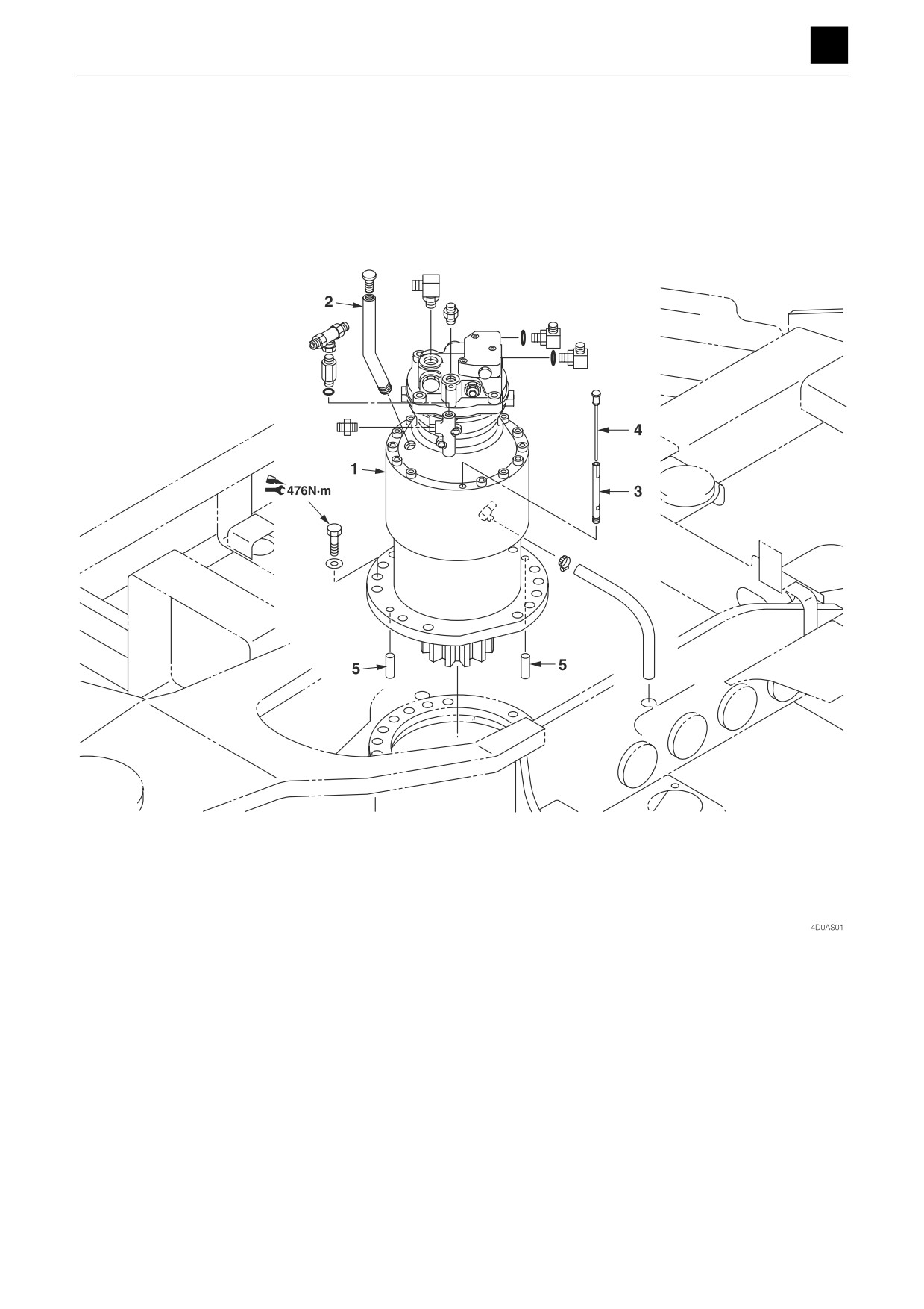
1. Slew motor
2. Oil feed port
3. Pipe
4. Oil gauge
5. Parallel pin
1
SLEW EQUIPMENT
4D0AS00
DISASSEMBLY AND ASSEMBLY
4
SLEW EQUIPMENT
Removing the slew motor
1. Disconnect the hydraulic hoses from the slew motor
(1).
2. Remove the bolts from the slew motor.
Bolt: ThreeBond #1324
Bolt: 476 N·m (351 ft.-lb)
3. Raise the slew motor (1), and remove it.
Slew motor: 170 kg (375 lb)
Installing the slew motor
To install, follow the same procedures as for removal but
in the reverse order.
2
SLEW EQUIPMENT
4D0AS00
DISASSEMBLY AND ASSEMBLY
4
SLEW EQUIPMENT
Slew bearing
Construction
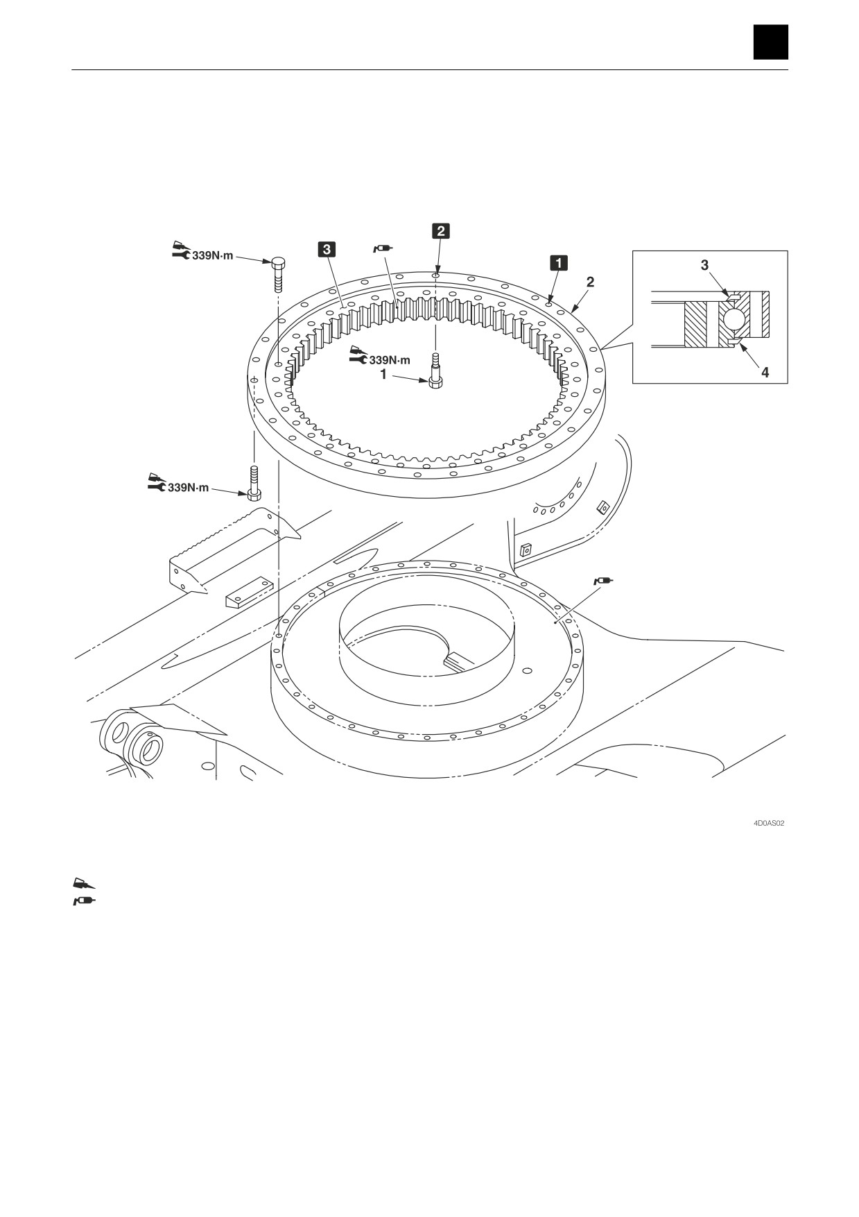
ThreeBond #1324
Grease the tooth surfaces and grease bus with lithium grease EP-2.
Approx. 12 L (12.7 US qt.)
1 Supply port hole
1. Reamer bolt
2 Use a reamer bolt at this position only
2. Slew bearing
3 "S" die stamp
3. Seal
4. Seal
3
SLEW EQUIPMENT
4D0AS00
DISASSEMBLY AND ASSEMBLY
4
SLEW EQUIPMENT
Removing the slew bearing
1. Remove the hoe attachment.
“Removing the hoe attachment”
2. Remove the upper frame.
3. Remove the fixing bolts for the inner race.
Bolt: ThreeBond #1324
Bolt: 339 N·m (250 ft.-lb)
4. Raise the slew bearing (2), and remove it.
Slew bearing: 200 kg (441 lb)
Installing the slew bearing
To install, follow the same procedures as for removal but
in the reverse order.
• Refer to the construction diagram for the positions of
the reamer bolts and the grease supply port.
• Grease the tooth surfaces and grease bus with lithium
grease EP-2.
4
SLEW EQUIPMENT
4D0AS00
DISASSEMBLY AND ASSEMBLY
4
SLEW EQUIPMENT
Swivel joint
Construction
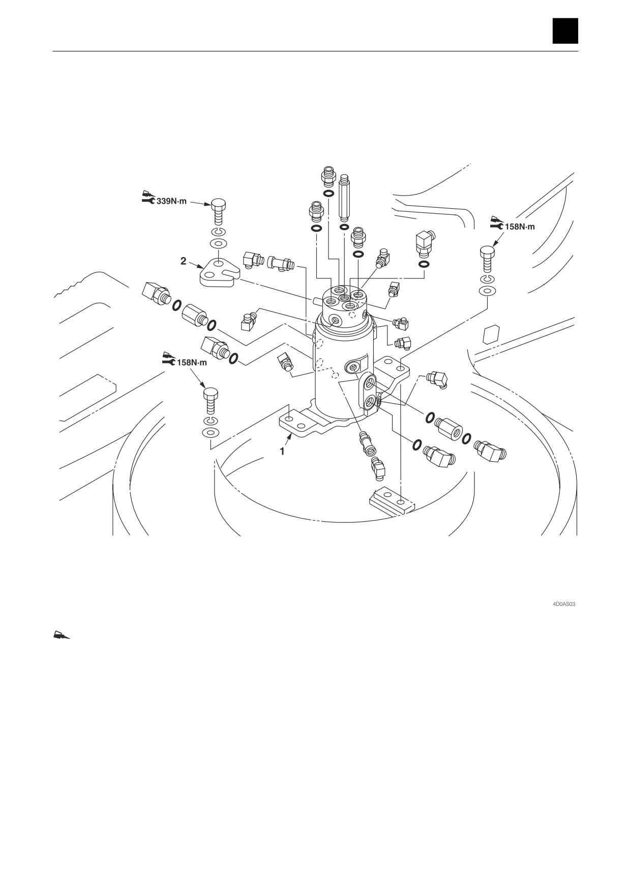
ThreeBond #1324
1. Swivel joint
2. Stopper
5
SLEW EQUIPMENT
4D0AS00
DISASSEMBLY AND ASSEMBLY
4
SLEW EQUIPMENT
Removing the swivel joint
1. Remove the upper frame.
“Removing the upper frame”
2. Disconnect the hydraulic hoses from the swivel joint
(1).
3. Take out the bolts holding the swivel joint (1) in place,
and remove the swivel joint (1).
Bolt: ThreeBond #1324
Bolt: 158 N·m (117 ft.-lb)
4. Raise the swivel joint (1), and remove it.
Swivel joint: 24 kg (53 lb)
Installing the swivel joint
For installation, follow the same procedures as for remov-
al but in the reverse order.
• When installing the swivel joint, secure it in place tem-
porarily using bolts, and position the center using a
dial gauge.
• Adjust the position so that the center offset is 1 mm
(0.0394 in.) or less.
6
SLEW EQUIPMENT
4D0AS00
DISASSEMBLY AND ASSEMBLY
UPPER FRAME 4
UPPER FRAME
Upper frame
Construction
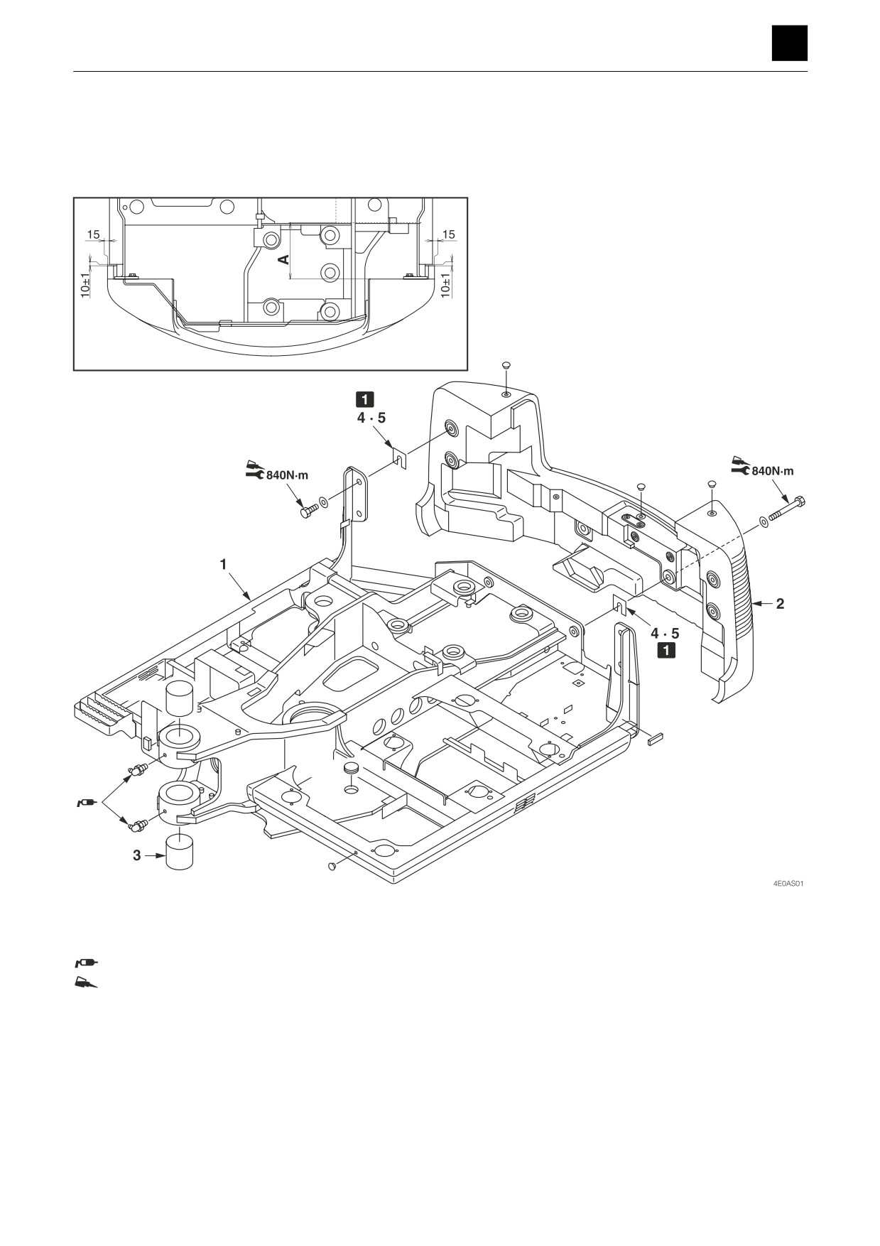
1 Adjust the shim so that dimension “A” on the top surface of the hydraulic tank and top surface of the counterweight
is 425 mm (16.7 in.).
Apply molybdenum disulfide grease.
ThreeBond #1324
1. Upper frame
2. Counterweight
3. Bushing
4. Shim (Selected usage)
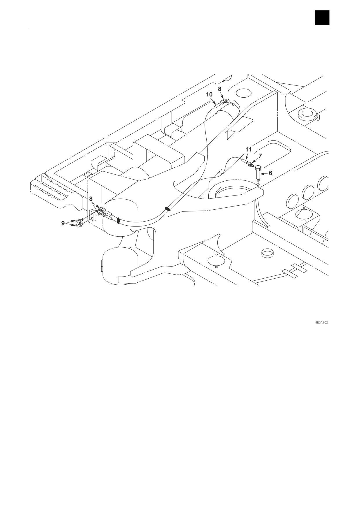
5. Shim (Selected usage)
1
UPPER FRAME
4E0AS00
DISASSEMBLY AND ASSEMBLY
UPPER FRAME 4
6. Elbow
7. Connector
8. Elbow
9. Grease fitting
10. Tube
11. Tube
2
UPPER FRAME
4E0AS00
DISASSEMBLY AND ASSEMBLY
4
UPPER FRAME
Removing the upper frame
1. Remove the hoe attachment.
“Removing the hoe attachment”
2. Take out the cab.
“Removing the cab”
3. Remove the covers.
“Removing the covers”
4. Remove the hydraulic hoses from the swivel joint.
“Removing the swivel joint”
5. Take out the bolts holding the swivel joint stopper in
place, and remove the stopper.
“Removing the swivel joint”
Bolt: 339 N·m (250 ft.-lb)
ThreeBond #1324
6. Disconnect the elbow (6) from the slew bearing.
7. Remove all of the fixing bolts for the outer race of the
slew bearing except for two at the front of the ma-
chine and two at the rear.
• When installing the slew bearing, be sure to align
it with the positions of the grease supply port and
the reamer bolt.
“Removing the slew bearing”
Bolt: ThreeBond #1324
Bolt: 339 N·m (250 ft.-lb)
8. Raise the upper frame (1) temporarily, and remove
the remaining bolts while balancing the upper frame
(1).
9. Raise the upper frame, and remove it.
Installing the upper frame
To install, follow the same procedures as for removal but
in the reverse order.
3
UPPER FRAME
4E0AS00
DISASSEMBLY AND ASSEMBLY
UPPER FRAME 4
Covers
Construction
X
Y
X
X
Y
4
UPPER FRAME
4E0AS00
DISASSEMBLY AND ASSEMBLY
UPPER FRAME 4
ThreeBond #1324
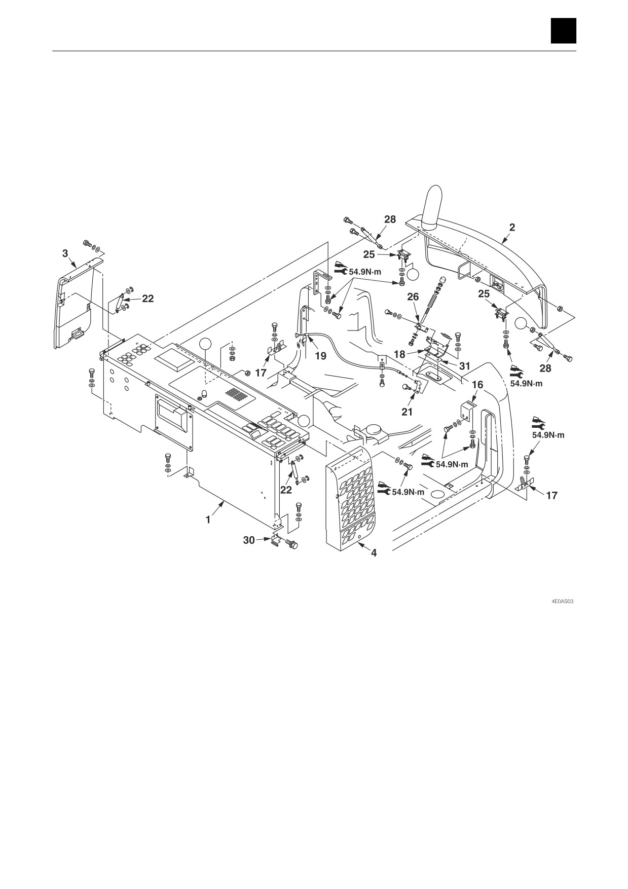
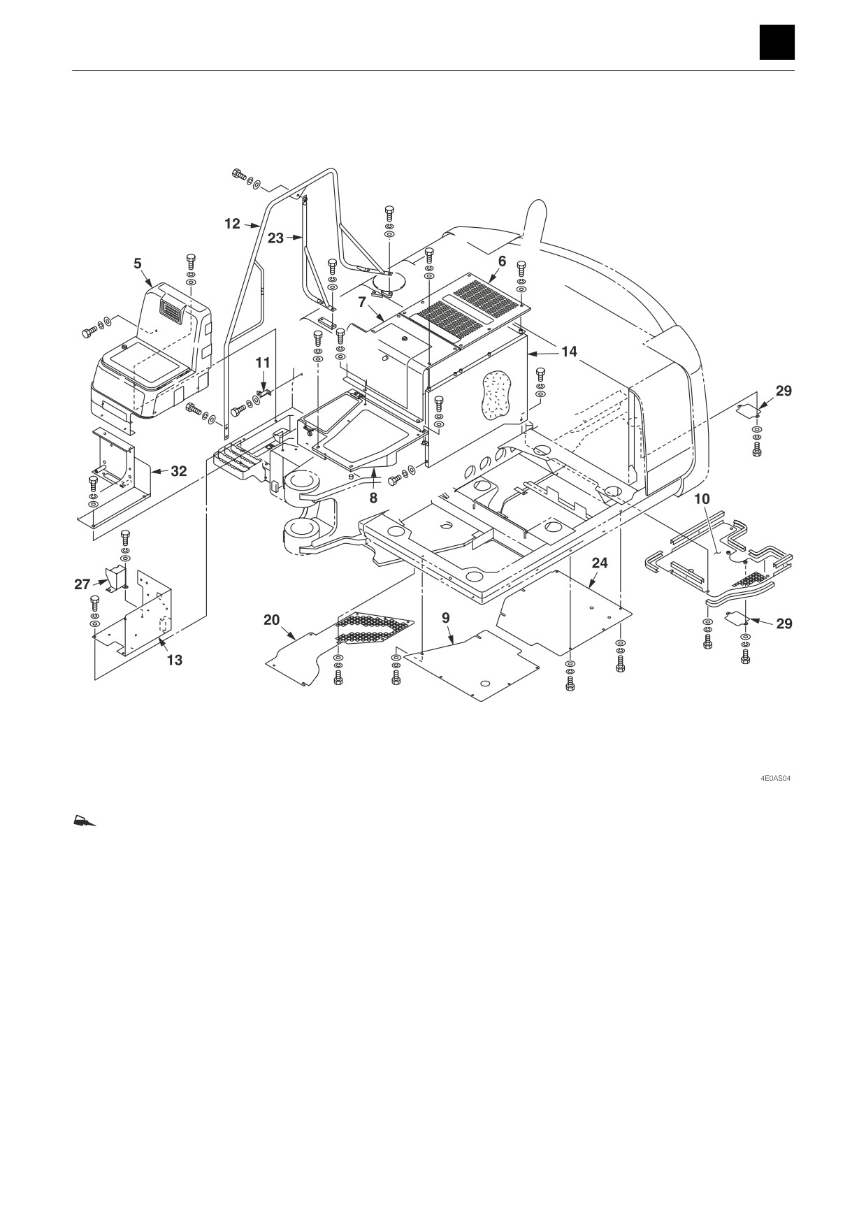
1. Engine cover (Front)
9. Undercover
17. Hook
25. Hinge
2. Engine hood
10. Undercover assembly
18. Bracket
26. Bracket
3. Side cover R
11. Bracket
19. Wire
27. Cover
4. Side cover L
12. Handrail
20. Undercover
28. Gas Spring
5. Front cover
13. Toolbox
21. Plate
29. Cover
6. Center cover T
14. Partition plate
22. Gas Spring
30. Plate
7. Center cover F
15. Stay
23. Handrail
31. Shim
8. Center cover F
16. Bracket
24. Undercover
32. Toolbox
5
UPPER FRAME
4E0AS00
DISASSEMBLY AND ASSEMBLY
4
UPPER FRAME
Removing the covers
1. Remove the battery ground cable from the battery
terminal.
2. Remove the engine hood (2).
a. Open the engine hood, and raise it up temporari-
ly.
b. Disconnect the electrical wires connected to the
engine hood.
c. Remove the gas spring (28).
d. Remove the fixing bolts for the hinge part.
Bolt: ThreeBond #1324
Bolt: 54.9 N·m (40.5 ft.-lb)
Engine hood: 34 kg (75 lb)
3. Remove the side cover R (3) and side cover L (4).
a. Open the side cover, and suspend it temporarily.
b. Remove the gas spring (22).
c. Remove the fixing bolts for the hinge part.
Bolt: ThreeBond #1324
Bolt: 54.9 N·m (40.5 ft.-lb)
4. Remove the center covers F (7) and (8).
5. Remove the center cover T (6) and the plate (14).
6. Remove the front cover (5).
• Disconnect the electrical wiring from the front
cover before attempting to remove the front cover
itself.
7. Remove the front engine cover (1).
• Take out the equipment fixing bolts screwed into
the cover to remove the device from the cover in
advance.
: 63 kg (140 lb)
Installing the covers
To install, follow the same procedures as for removal but
in the reverse order.
6
UPPER FRAME
4E0AS00
DISASSEMBLY AND ASSEMBLY
UPPER FRAME 4
Cab
Construction
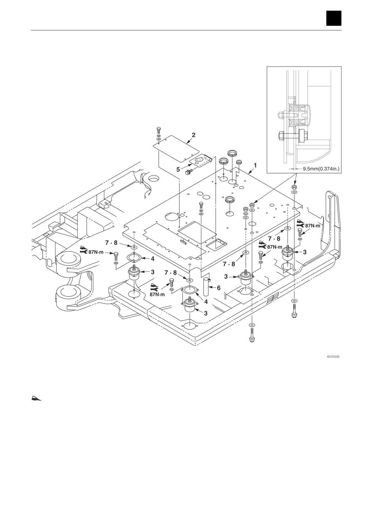
If the width of the clearance between the machine body
and the cab is not kept constant (9 mm (0.35 in.) or be-
low), adjust the width using the washers (7) and (8).
Bolt: ThreeBond #1324
1. Floor plate
5. Cover assembly
2. Cover
6. Pipe
3. Cab mount
7. Washer
4. Holder
8. Washer
7
UPPER FRAME
4E0AS00