Takeuchi Hydraulic excavator TB1140 (Serial No. 514400002~). Operator's Manual - page 3
FUNCTION
3
PILOT VALVE (CONTROL LEVER)
PILOT VALVE (CONTROL LEVER)
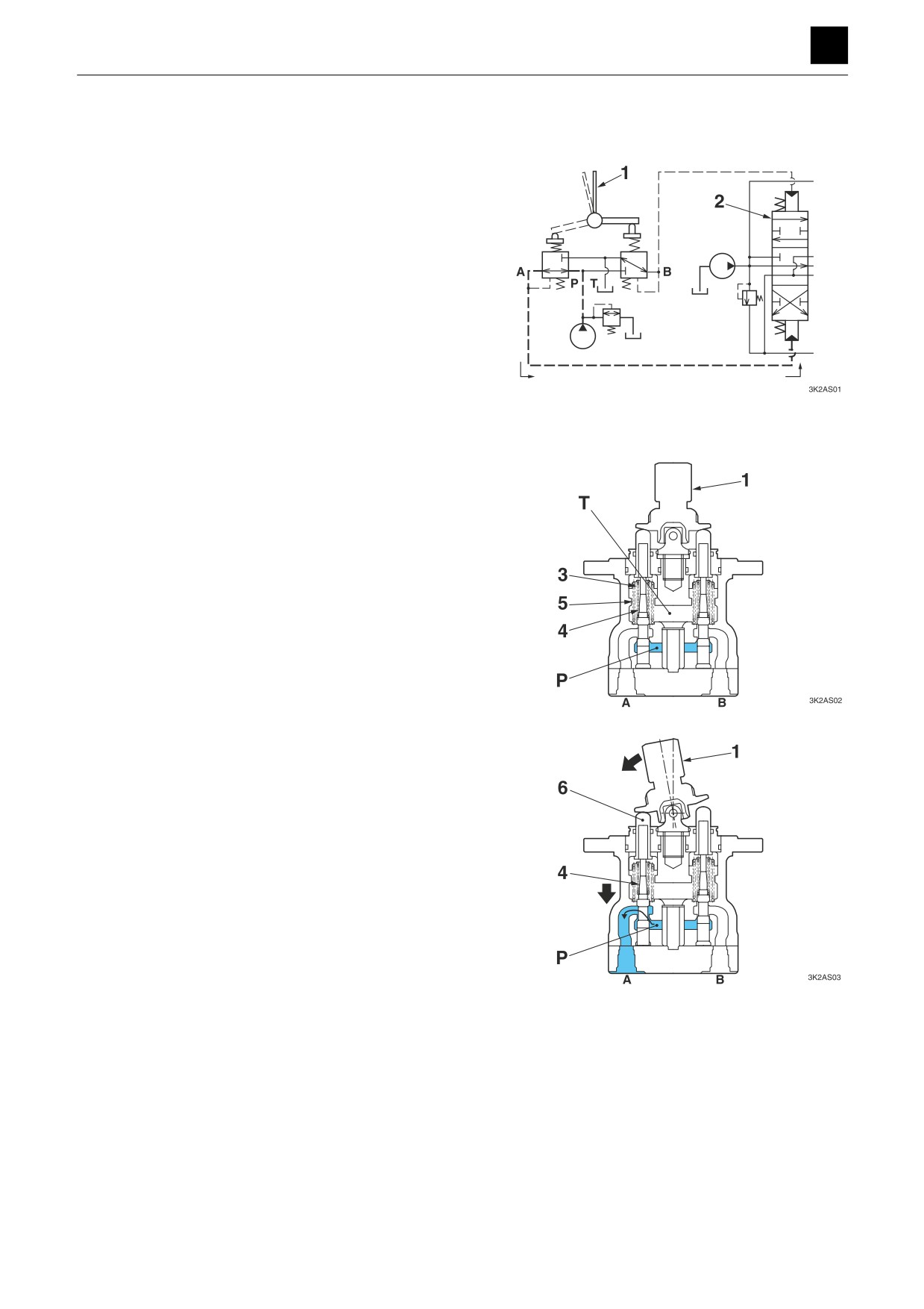
The pilot valve is a remote-controlled valve with a reduc-
ing valve system used to operate the spool in the control
valve. The pilot valve comes with right and left control le-
vers.
The pilot valve casing contains a vertical shaft hole that
incorporates a reducing valve. When the lever is tilted,
the push rod and spring seat are pushed down, chang-
ing the spring force of the secondary pressure.
The casing contains the oil inlet port P (the primary pres-
sure) and the tank port T. The secondary pressure corre-
sponding to the changes in operating angle performed
by the lever (1) can be provided through the output ports
A and B located below the vertical shaft hole. The sec-
ondary pressure functions as the pilot pressure to actu-
ate the spool of the control valve (2).
When the lever (1) is in the neutral position:
The force of the spring (3) that determines the output
pressure (secondary pressure) of the pilot valve is not
conveyed to the spool (4). This causes the spool (4) to be
pushed up by the return spring (5), and the output ports
A and B are connected to the tank port T. This causes the
pressures in the ports A and B to be equal to the pres-
sure in the tank port T.
When the lever (1) is tilted:
When the lever (1) is tilted and the push rod (6) is
pushed, the spool (4) moves downward and the input
port P is connected with the output port A. Then, the oil
from the pilot pump flows into the output port A, generat-
ing a pressure.
1
PILOT VALVE (CONTROL LEVER)
3K2AS00
FUNCTION
3
PILOT VALVE (CONTROL LEVER)
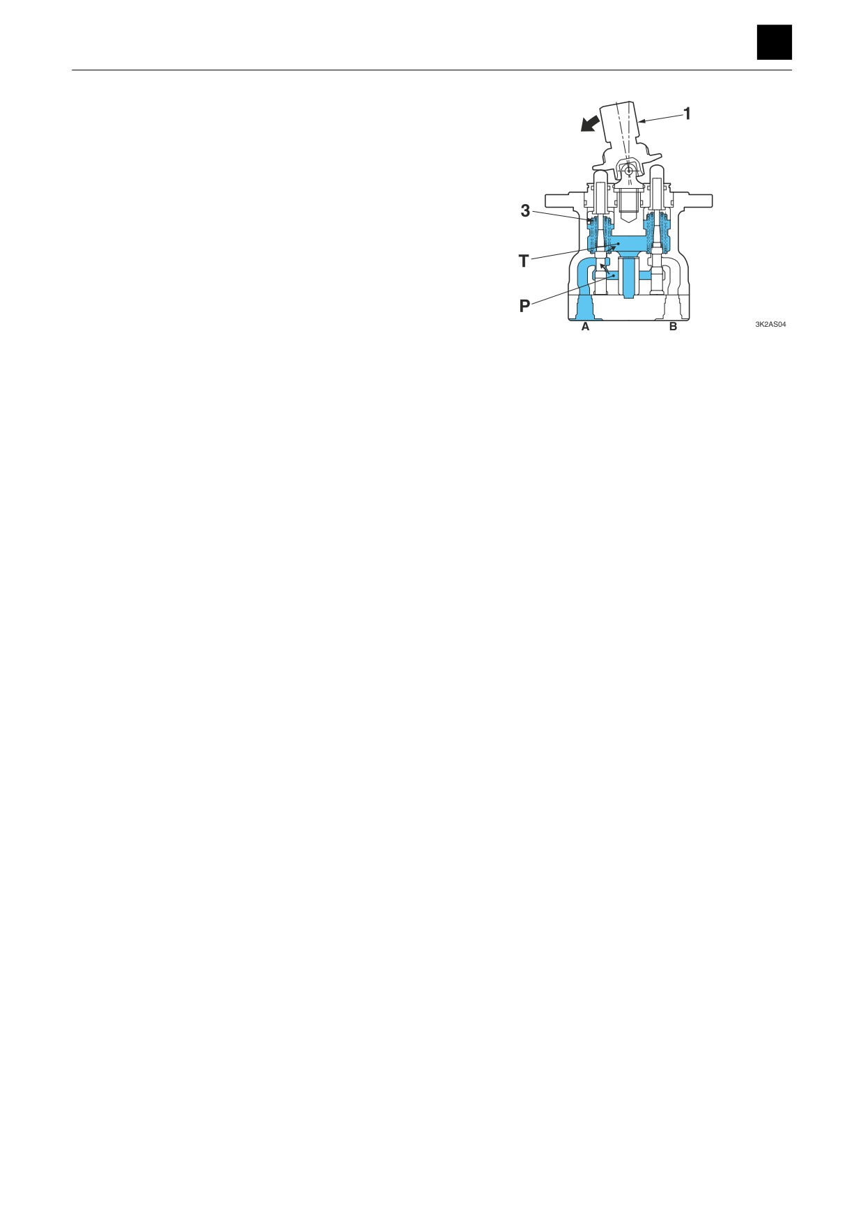
When the lever (1) is kept at a certain position:
When the pressure in the output port A increases to the
level equivalent to the force of the spring (3) set by the
inclination of the lever (1), the hydraulic pressure is bal-
anced with the spring force. When the pressure in the
output port A becomes higher than the set spring force,
the output port A is disconnected from the input port P
while it is now connected with the tank port T. When the
pressure in the output port A becomes lower than the set
spring force, the output port A is connected with the input
port P, while it is now disconnected from the tank port T.
Thus, the secondary pressure is always kept constant.
2
PILOT VALVE (CONTROL LEVER)
3K2AS00
FUNCTION
3
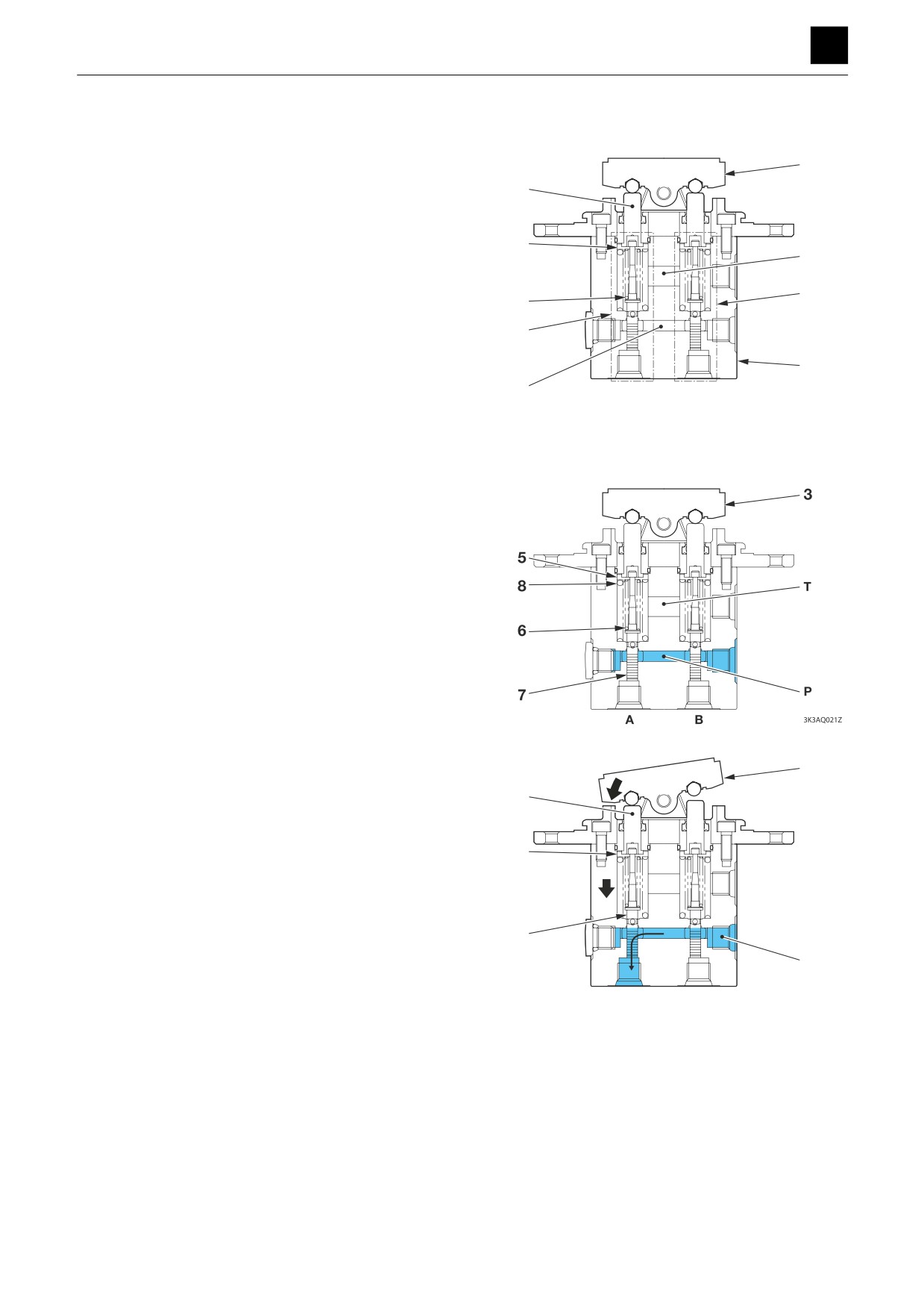
PILOT VALVE (SWING)
PILOT VALVE (SWING)
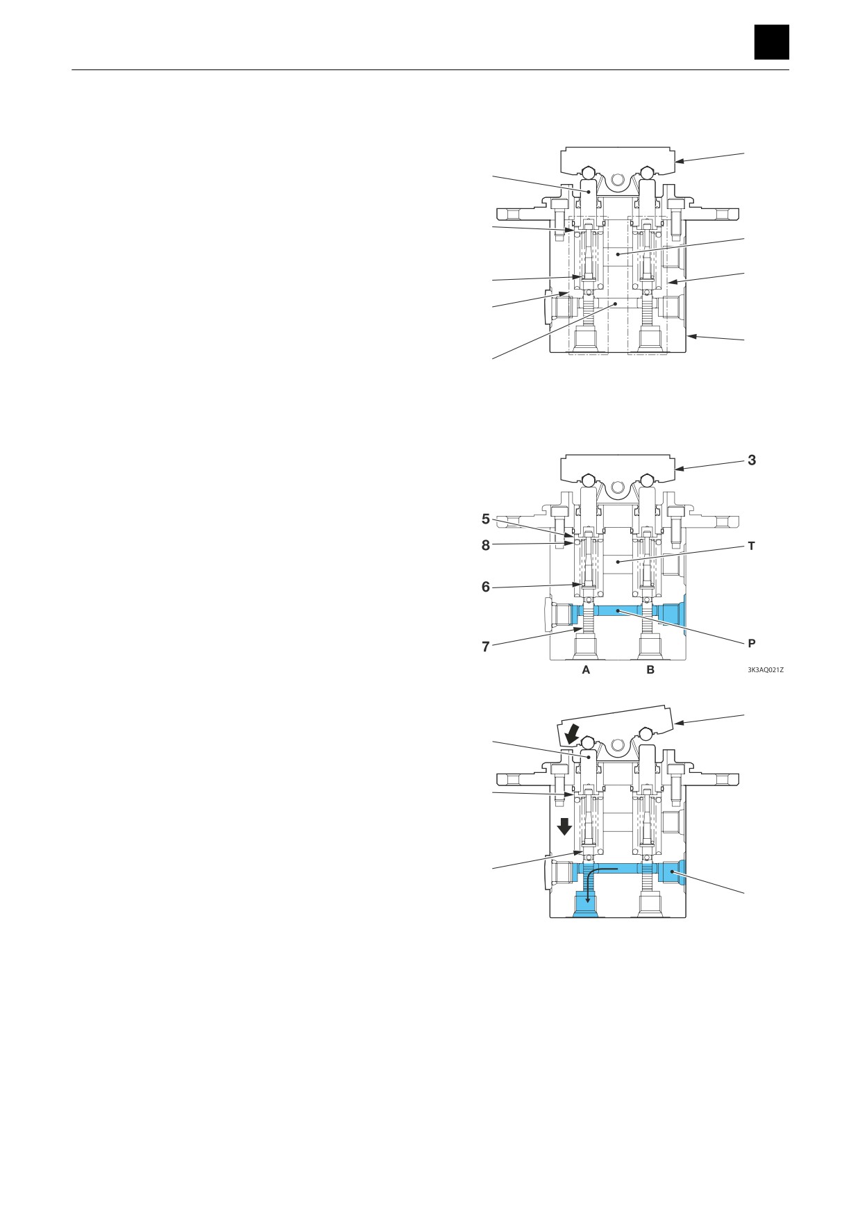
The pilot valve is a remote-controlled valve with a reduc-
3
ing valve system used to operate the spool in the control
valve. The pilot valve (swing) is located on the left side of
4
the driver’s seat on the floor.
The pilot valve casing (1) contains a vertical shaft hole
5
that incorporates a reducing valve (2). When the cam (3)
T
is tilted, the push rod (4) and spring seat (5) are pushed
down, which changes the pressure of the secondary
2
6
pressure spring (6).
The casing (1) contains the oil inlet port P (primary pres-
2
sure) and the tank port T. The secondary pressure which
corresponds to changes in operating angle produced
1
using the cam (3) can be provided through the output
P
A
B
3K3AQ01Z
ports A and B located below the vertical shaft hole. The
secondary pressure functions as the pilot pressure to ac-
tivate the spool of the control valve.
When the cam (3) is in the neutral position:
The force of the spring (6) that determines the output
pressure (secondary pressure) of the pilot valve is not
conveyed to the spool (7). This causes the spool (7) to be
pushed up by the return spring (8) and spring sheet (5),
and the output ports A and B are connected to the tank
port T, which makes the pressures in the ports A and B
be equal to the pressure in the tank port T.
When the cam (3) is tilted:
3
When the cam (3) is tilted and the push rod (4) is pushed,
4
the spring sheet (5) and spool (7) move downward, and
the input port P is connected to the output port A. The oil
from the pilot pump then flows into the output port A to
5
generate a pressure.
7
P
A
B
3K3AQ03Z
1
PILOT VALVE (SWING)
3K3AQ00
FUNCTION
3
PILOT VALVE (SWING)
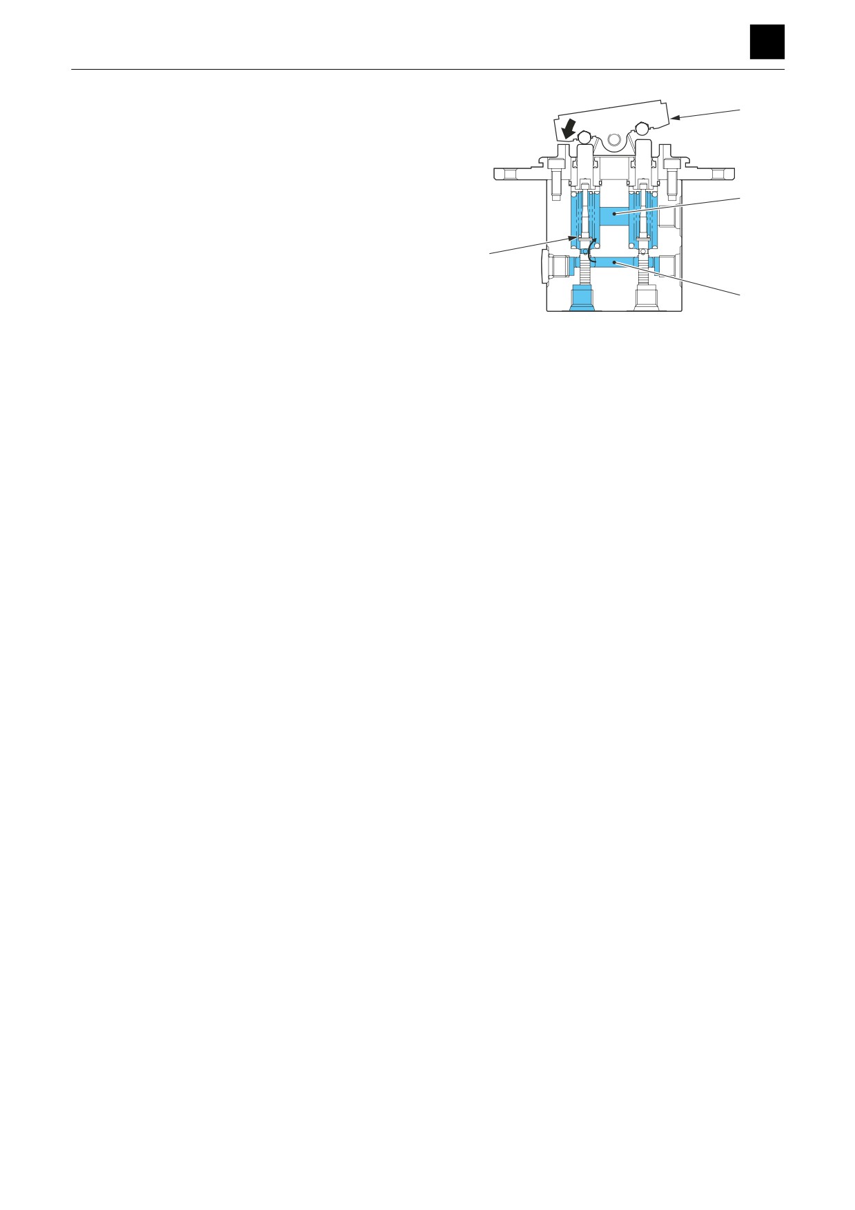
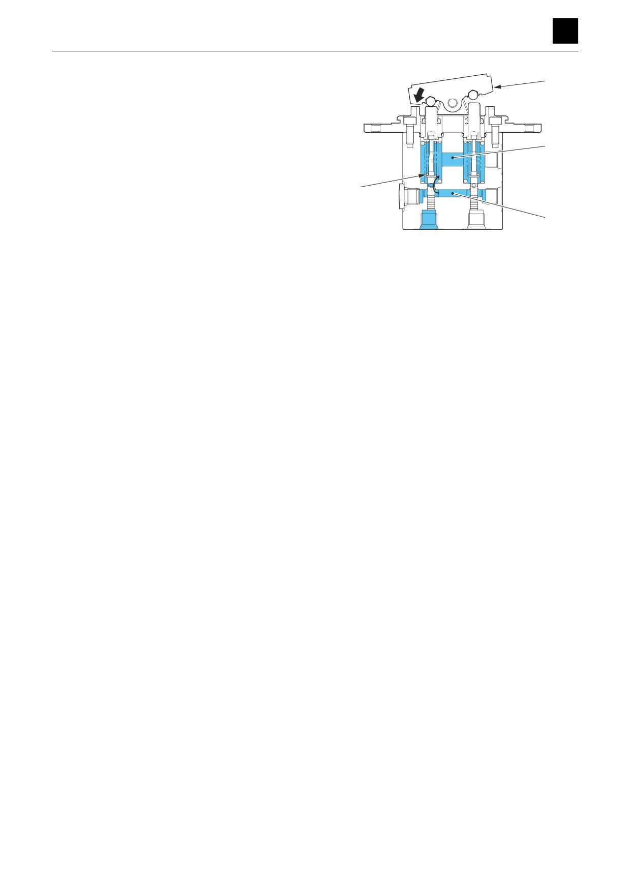
When the cam (3) is kept at a certain position:
3
When the pressure in the output port A increases to a lev-
el equivalent to the force of the spring (6) set by the incli-
nation of the cam (3), the hydraulic pressure is balanced
with the spring force. When the pressure in the output
port A becomes higher than the set spring force, the out-
T
put port A is disconnected from the input port P and then
becomes connected to the tank port T. When the pres-
sure in the output port A drops below than the set spring
6
force, the output port A becomes connected to the input
port P and it is then disconnected from the tank port T.
P
The secondary pressure is thus always kept constant.
A
B
3K3AQ04Z
2
PILOT VALVE (SWING)
3K3AQ00
FUNCTION
3
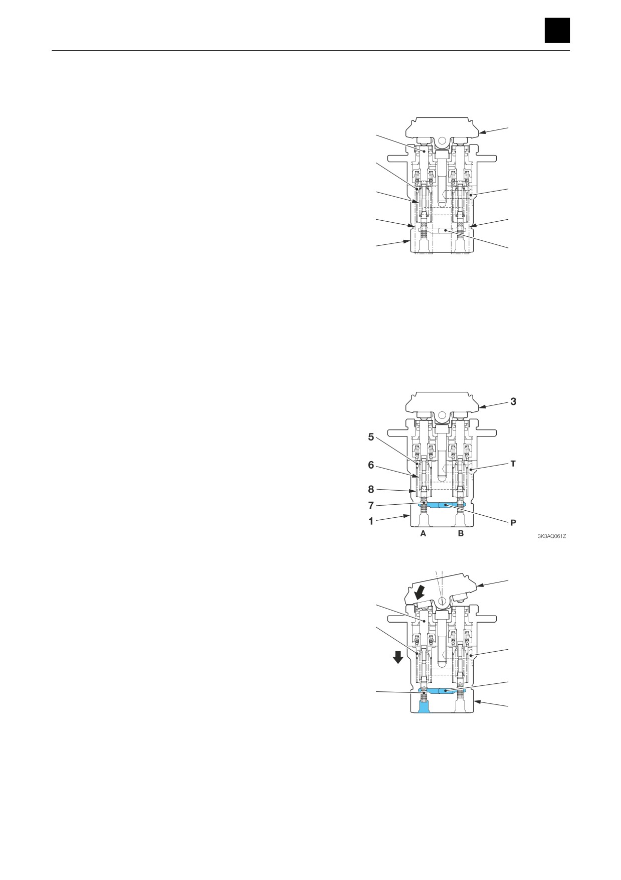
PILOT VALVE (BLADE)
PILOT VALVE (BLADE)
The pilot valve is a remote-controlled valve with a reduc-
3
ing valve system used to operate the spool in the control
valve. The pilot valve (blade) is located on the right side
4
of the driver’s seat on the floor.
The pilot valve casing (1) contains vertical shaft holes
5
that incorporatea reducing valves (2). When the cam (3)
T
is tilted, the push rod (4) and spring seat (5) are pushed
down, which changes the pressure of the secondary
2
6
pressure spring (6).
The casing (1) contains the oil inlet port P (primary pres-
2
sure) and the tank port T. The secondary pressure which
corresponds to changes in operating angle produced
1
using the cam (3) can be provided through the output
P
A
B
3K3AQ01Z
ports A and B located below the vertical shaft hole. The
secondary pressure functions as the pilot pressure to ac-
tivate the spool of the control valve.
When the cam (3) is in the neutral position:
The force of the spring (6) that determines the output
pressure (secondary pressure) of the pilot valve is not
conveyed to the spool (7). This causes the spool (7) to be
pushed up by the return spring (8) and spring sheet (5),
and the output ports A and B are connected to the tank
port T, which makes the pressures in the ports A and B
be equal to the pressure in the tank port T.
When the cam (3) is tilted:
3
When the cam (3) is tilted and the push rod (4) is pushed,
4
the spring sheet (5) and spool (7) move downward, and
the input port P is connected to the output port A. The oil
from the pilot pump then flows into the output port A to
5
generate a pressure.
7
P
A
B
3K3AQ03Z
1
PILOT VALVE (BLADE)
3K3AQ01
FUNCTION
3
PILOT VALVE (BLADE)
When the cam (3) is kept at a certain position:
3
When the pressure in the output port A increases to a lev-
el equivalent to the force of the spring (6) set by the incli-
nation of the cam (3), the hydraulic pressure is balanced
with the spring force. When the pressure in the output
port A becomes higher than the set spring force, the out-
T
put port A is disconnected from the input port P and then
becomes connected to the tank port T. When the pres-
sure in the output port A drops below than the set spring
6
force, the output port A becomes connected to the input
port P and it is then disconnected from the tank port T.
P
The secondary pressure is thus always kept constant.
A
B
3K3AQ04Z
2
PILOT VALVE (BLADE)
3K3AQ01
FUNCTION
3
PILOT VALVE (TRAVEL)
PILOT VALVE (TRAVEL)
The pilot valve is a remote-controlled valve with a reduc-
ing valve system used to operate the spool in the control
valve. The pilot valve (travel) is located the below the
3
4
travel lever near the driver’s seat.
The pilot valve casing (1) contains vertical shaft holes
5
that incorporate reducing valves (2). When the cam (3) is
tilted, the push rod (4) and spring seat (5) are pushed
6
T
down, which changes the pressure of the secondary
pressure spring (6).
The casing (1) contains the oil inlet port P (primary pres-
2
2
sure) and the tank port T. The secondary pressure which
corresponds to changes in operating angle produced
1
P
using the cam (3) can be provided through the output
A
B
3K3AQ05Z
ports A and B located below the vertical shaft hole. The
secondary pressure functions as the pilot pressure to ac-
tivate the spool of the control valve.
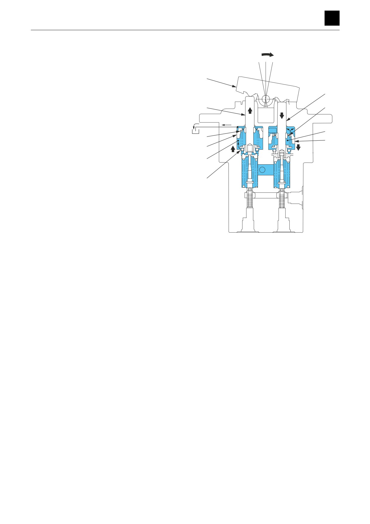
This pilot valve also comes equipped with a damping
function to prevent hunting oscillation resulting from the
supply of oil lagging behind from occurring during sud-
den operation.
When the cam (3) is in the neutral position:
The force of the spring (6) that determines the output
pressure (secondary pressure) of the pilot valve is not
conveyed to the spool (7). This causes the spool (7) to be
pushed up by the return spring (8) and spring sheet (5),
and the output ports A and B are connected to the tank
port T, which makes the pressures in the ports A and B
be equal to the pressure in the tank port T.
When the cam (3) is tilted:
When the cam (3) is tilted and the push rod (4) is pushed,
3
the spring sheet (5) and spool (7) move downward, and
the input port P is connected to the output port A. The oil
4
from the pilot pump then flows into the output port A to
5
generate a pressure.
T
P
7
1
A
B
3K3AQ07Z
1
PILOT VALVE (TRAVEL)
3K3AQ02
FUNCTION
3
PILOT VALVE (TRAVEL)
When the cam (3) is kept at a certain position:
When the pressure in the output port A increases to a lev-
3
el equivalent to the force of the spring (6) set by the incli-
nation of the cam (3), the hydraulic pressure is balanced
with the spring force. When the pressure in the output
port A becomes higher than the set spring force, the out-
put port A is disconnected from the input port P and then
T
becomes connected to the tank port T. When the pres-
sure in the output port A drops below than the set spring
6
force, the output port A becomes connected to the input
port P and it is then disconnected from the tank port T.
P
The secondary pressure is thus always kept constant.
A
B
3K3AQ08Z
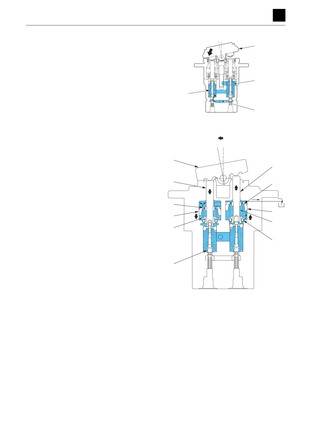
Damping function
The damping function prevents hunting oscillation from
occurring due to the supply of oil lagging behind during
sudden operation of the pilot valve.
When the cam (3) is tilted, which pushes the push rod (4)
3
on the port A side, the spool (7) and piston (9) move
4-1
downward. At this time, the oil in the piston chamber (10)
is discharged from the orifice (11) in the piston (9), which
4
12
generates a pressure. This damping pressure prevents
the push rod (4) from moving suddenly.
Meanwhile, the push rods (4-1) on the port B side are
moved upward by the spring (12) via the piston (13).
11
The ball (14) is pushed up, causing the oil in the tank
13
9
chamber to flow into the piston chamber (15), which pre-
15
vents the piston chamber (15) from experiencing a neg-
10
ative pressure. The oil outside of the piston chamber re-
turns to the tank through the tank channel in the top of the
14
casing.
7
A
B
3K3AQ09Z
2
PILOT VALVE (TRAVEL)
3K3AQ02
FUNCTION
3
PILOT VALVE (TRAVEL)
If the cam (3) is tilted all the way down and then tilted in
the opposite direction, the push rods (4-1) on the port B
side are pushed down, and the piston (13) is moved
downward.
At this time, the oil in the piston chamber (15) is dis-
3
charged from the orifice (16) in the piston, which gener-
ates a pressure.
4-1
Meanwhile, the push rod (4) on the port A side is moved
upward by the spring (17) via the piston (9).
4
16
The ball (14) is pushed up, causing the oil in the tank
channel to flow into the piston chamber (10), which pre-
vents the piston chamber (10) from experiencing a neg-
15
ative pressure. The oil outside of the piston chamber re-
17
13
turns to the tank from the tank channel connected to the
9
tank in the top of the casing.
10
The pilot valve is formed in this way so that the damping
function works to prevent hunting oscillation no matter
the position from which the handle is operated.
14
A
B
3K3AQ10Z
3
PILOT VALVE (TRAVEL)
3K3AQ02
FUNCTION
3
PROPORTIONAL CONTROL SOLENOID VALVE
PROPORTIONAL CONTROL SOLENOID VALVE
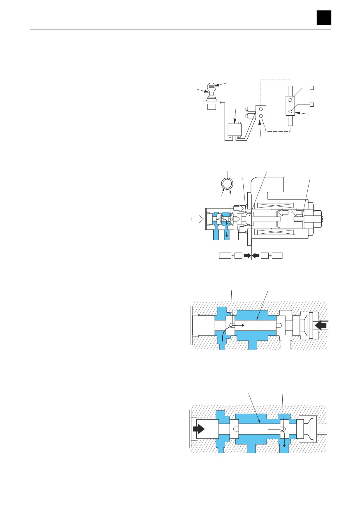
The proportional lever (2) and proportional amplifier (3)
of the pilot valve (1) control the driving current that flows
to the proportional control solenoid valve (4), which con-
trols the pilot pressure of the control valve (5) (auxiliary
2
1
section) whereby the flow rate of the auxiliary line piping
changes.
The proportional control solenoid valve controls the sec-
3
ondary pressure using the built-in proportional pressure-
5
educing valve. The secondary pressure generated cor-
responds to the changes in current because of the force
used to generate the secondary pressure being applied
to the solenoid in accordance with the amount of current
4
flowing through the coil.
3K4AQ01Z
When current flows through the solenoid, a thrust force
proportional to the current is generated and moves the
S
6
spool (6) so that the oil supplied from the port P is intro-
7
8
duced into the port A on the secondary pressure side,
S=A1-B1
which increases the pressure Pa of the port A.
The pressure Pa acts on the differential area S between
B1 A1
the cross section A1 and cross section B1 of the spool
Fk
(6), and the spool (6) is pushed to the solenoid side by
Fs
Fks
the oil pressure, Pa × s. The spool (6) stops at the posi-
Paxs
tion where the sum of the oil pressure, Pa × s, and the
force, Fk, exerted by the springs (7) is balanced with the
thrust force, Fs, generated by the solenoid. The weight,
P
A
T
Fks, of the spring (8) used for fine adjustment of the sec-
Paxs
Fk
Fs
Fks
ondary pressure acts in the direction (left) of assistance
3K4AQ02Z
of the thrust force from the solenoid.
When the thrust force is greater than a set value, the
spool (6) is moved to the left, which connects the port P
9
6
(supply side) and the port A (secondary side) together
through the notch (9).
P
A
T
3K4AQ03Z
When the thrust force is lower than a set value, the spool
(6) is moved to the right, which connects the port A (sec-
6
10
ondary side) and the port T (tank side) together through
the notch (10).
The opening areas of the notch (9) on the supply side
and the notch (10) on the discharge side are thus con-
trolled by the movement of the spool (6), and a second-
ary (pilot) pressure can be provided that corresponds to
the thrust force generated by the solenoid.
P
A
T
3K4AQ04Z
1
PROPORTIONAL CONTROL SOLENOID VALVE
3K4AQ00
FUNCTION
3
EMERGENCY SHUT-OFF VALVE
EMERGENCY SHUT-OFF VALVE
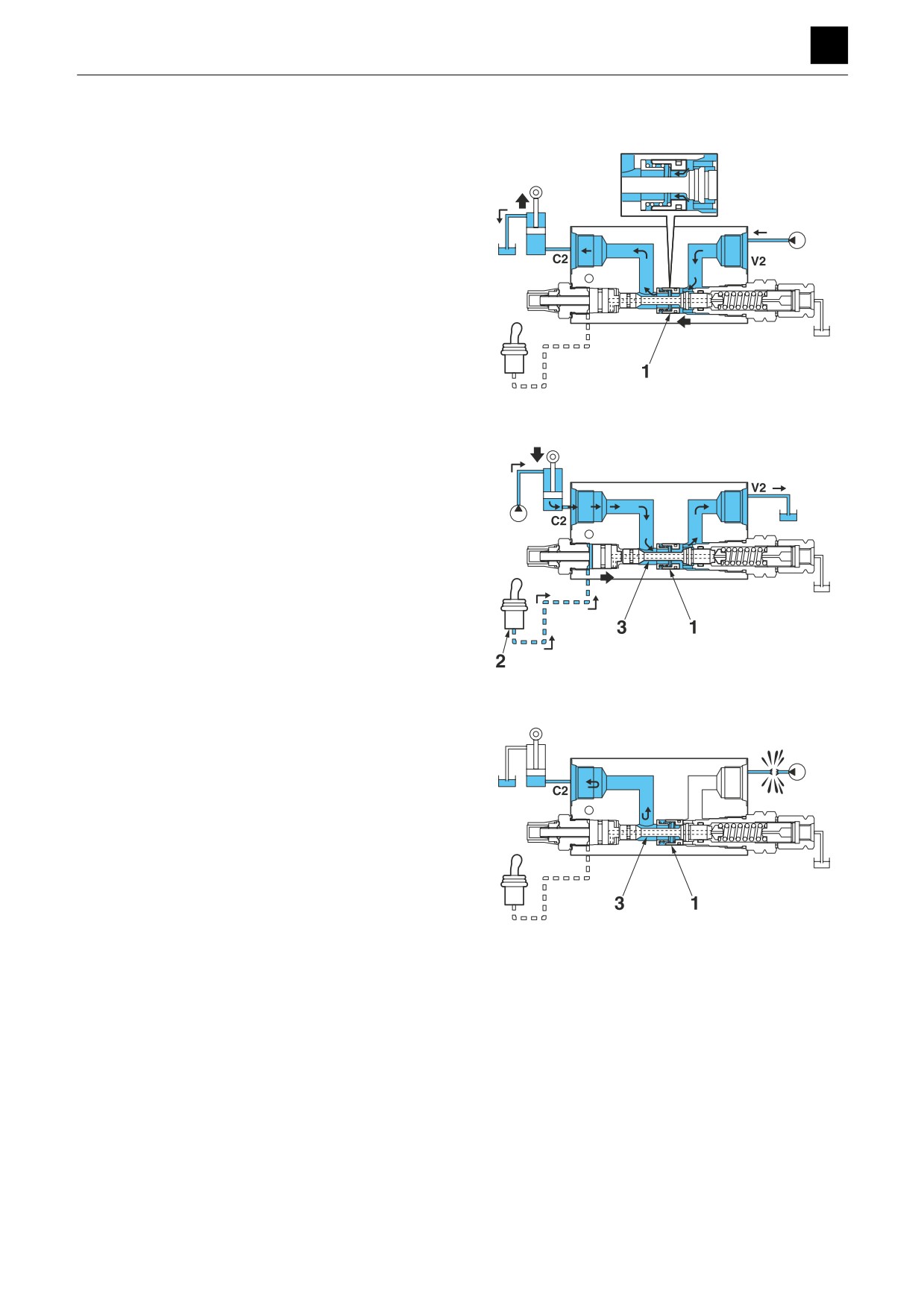
The emergency shut-off valve is used to keep the boom
or arm from falling to maintain safety by blocking and
shutting off the oil from the cylinder head side even if the
hydraulic hose should become damaged while the boom
or arm is being raised.
The pressure oil of the hydraulic pump pushes up the
check valve (1) from the port V2 while the boom or arm is
being raised and flows from the port C2 to the boom or
arm cylinder.
PIL
3K5AQ01Z
The pilot pressure is introduced into the port PIL from the
pilot valve (2) while the boom or arm is being lowered.
The pilot pressure moves the spool (3) to the left side
from the port PIL. The return oil from the cylinder flows
from the port C2 through the channels in the spool (3)
and check valve (1) to the tank channel from the port V2.
PIL
3K5AQ02Z
The channels in the check valve (1) and spool (3) are
blocked if the hydraulic hose becomes damaged, which
shuts off the oil on the cylinder head side to prevent the
boom and arm from falling even if either tries to go down.
PIL
3K5AQ03Z
1
EMERGENCY SHUT-OFF VALVE
3K5AQ00
FUNCTION
3
SOLENOID VALVE
SOLENOID VALVE
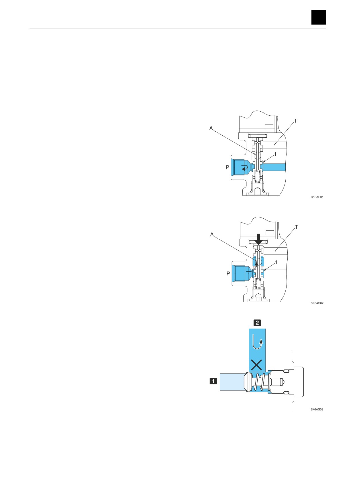
This valve switches circuit connections by moving the
spool using magnets and supplies the pilot pressure to
the pilot valve and 2nd-speed travel switch.
The pilot pressure is kept constant with the relief valve.
Solenoid valve
When the solenoid is not energized:
The oil in the port P (pump side) is blocked by the spool
(1).
The oil flows through the port A (on the pilot circuit side
of the pilot valve or 2nd-speed travel switch) and port T
(on the tank side), which results in the pressure of the
downstream pilot circuit being the same as the tank pres-
sure.
When the solenoid is energized:
A magnetic field is generated around the coil that causes
the push rod to be pulled downward and the spool (1) to
be pushed down. This causes the oil in the port P to flow
to the port A, and the pressure is transmitted to the lower
pilot circuit.
Check valve
The IN port is connected to the pump and the OUT port
to the accumulator.
This works to prevent a backward flow of oil from the OUT
port to the IN port side should the pressure in the IN port
become a negative pressure.
1 IN
2 OUT
1
SOLENOID VALVE
3K6AS00
FUNCTION
3
SHOCKLESS VALVE
SHOCKLESS VALVE
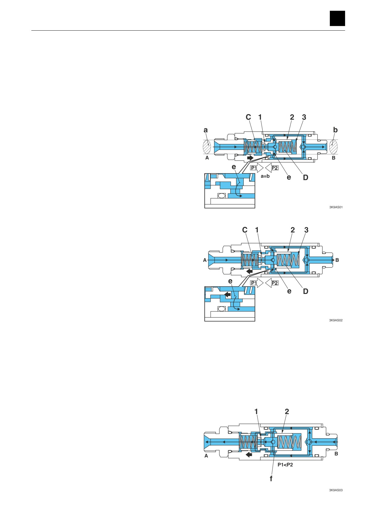
This valve controls the flow rate used to operate the con-
trol valve spool from the pilot valve and keeps it at a con-
stant rate when the boom is lowered and works to pre-
vent the machine from vibrating so that the boom does
not drop suddenly.
Port A side Port B side
The hydraulic oil supplied from port A passes through the
orifice (1) and flows into the port B through a side hole in
the plunger (2).
The pressure P1 flows into chamber C on the left side of
the plunger (2) before closing and the pressure P2 flows
into chamber D on the right side after closing. Because
the areas a and b of the plunger (2) affected by pressure
are the same size, the pressure differential PC between
P1 and P2 is determined by the force of the spring (3).
When the pressure in port A increases causing the flow
rate through the orifice (1) to increase, the pressure dif-
ferential between P1 and P2 rises, and the plunger (2)
moves to the right and pushes on the spring (3). When
this occurs, the opening e through which pressure flows
from outside of the valve decreases in size, which acts to
decrease the flow rate for flow from the outside of the
valve.
The opening e is closed and becomes balanced so that
the plunger (2) becomes static until the pressure differ-
ential between P1 and P2 becomes equal to the pressure
differential PC set initially.
In addition, should the reverse occur and the pressure in
the port A decrease causing the flow rate through the or-
ifice (1) to decrease, the pressure differential between P1
and P2 drops, and the plunger (2) moves to the left of the
spring (3), and the opening e becomes bigger, which en-
ables the hydraulic oil to flow from port A more easily. The
plunger (2) then moves and becomes static until the
pressure differential between P1 and P2 becomes equal
to the pressure differential PC set initially.
That is, if the pressure differential for the port A side and
port B side of the valve is changed, the pressure before
and after the orifice (1) inside the valve becomes con-
stant.
Port B side Port A side
When hydraulic oil is supplied to port B, the hydraulic oil
passes through the orifice (1) and flows into port A. At this
time, due to resistance with regard to allowing passage in
the orifice (1), the relationship in pressure between P1 and
P2 becomes such that P1 < P2, and the plunger (2) moves
to the left side. When this occurs, the circuit for section f
opens, and the hydraulic oil from port B flows through the
side hole in the plunger (2), and the entire volume flows into
port A.
If the hydraulic oil is cut off, the plunger (2) returns to the
center position using the force of the spring.
1
SHOCKLESS VALVE
3K9AS00
FUNCTION
3
CYLINDERS
CYLINDERS
The pressure oil flowing alternately in through the outlet
and inlet on both sides (head and rod sides) of the piston
acts on the piston and the force produced causes the
piston to move back and forth.
For those cylinders with a cushion mechanism, the shock
resulting from the piston colliding with the cover at the
stroke end is dampened by the mechanism.
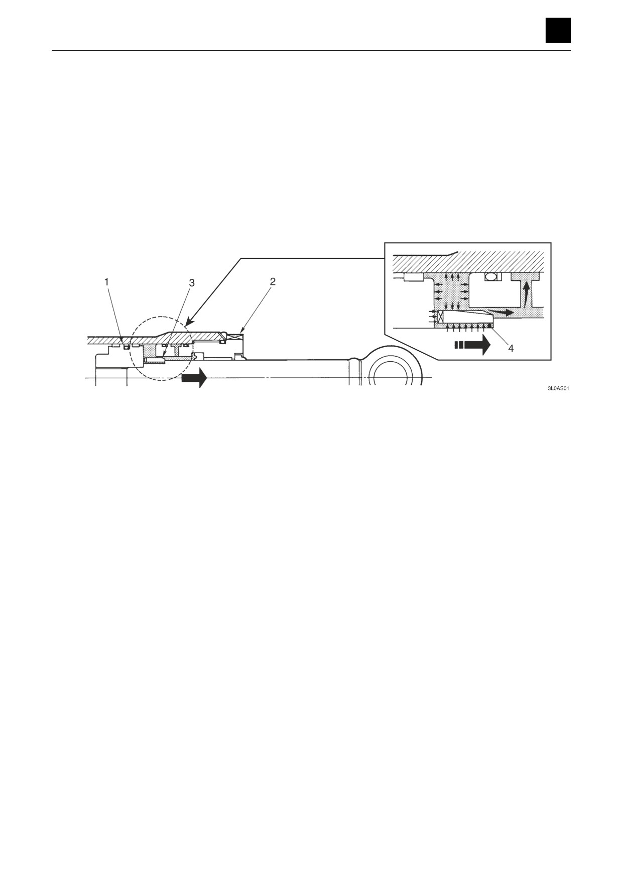
Cushion mechanism
When the piston (1) approaches the stroke end and ap-
pears likely to bump into the cover (2), the cushion bear-
ing (3) that is moving ahead of the piston enters the cush-
ion seal (4). As this shuts off the return passage for the
hydraulic oil on the back of the piston, the oil is expelled
only from the throttle hole or the groove provided in the
cushion bearing (3). This causes the piston (1) backpres-
sure to increase, slowing the piston speed.
1
CYLINDERS
3L0AS00
FUNCTION
TRAVEL MOTOR 3
TRAVEL MOTOR
This section includes descriptions of the hydraulic motor,
which is driven by hydraulics, the brake valve, the relief
valve, the 2nd-speed switching mechanism, the parking
brake, and the reduction gears.
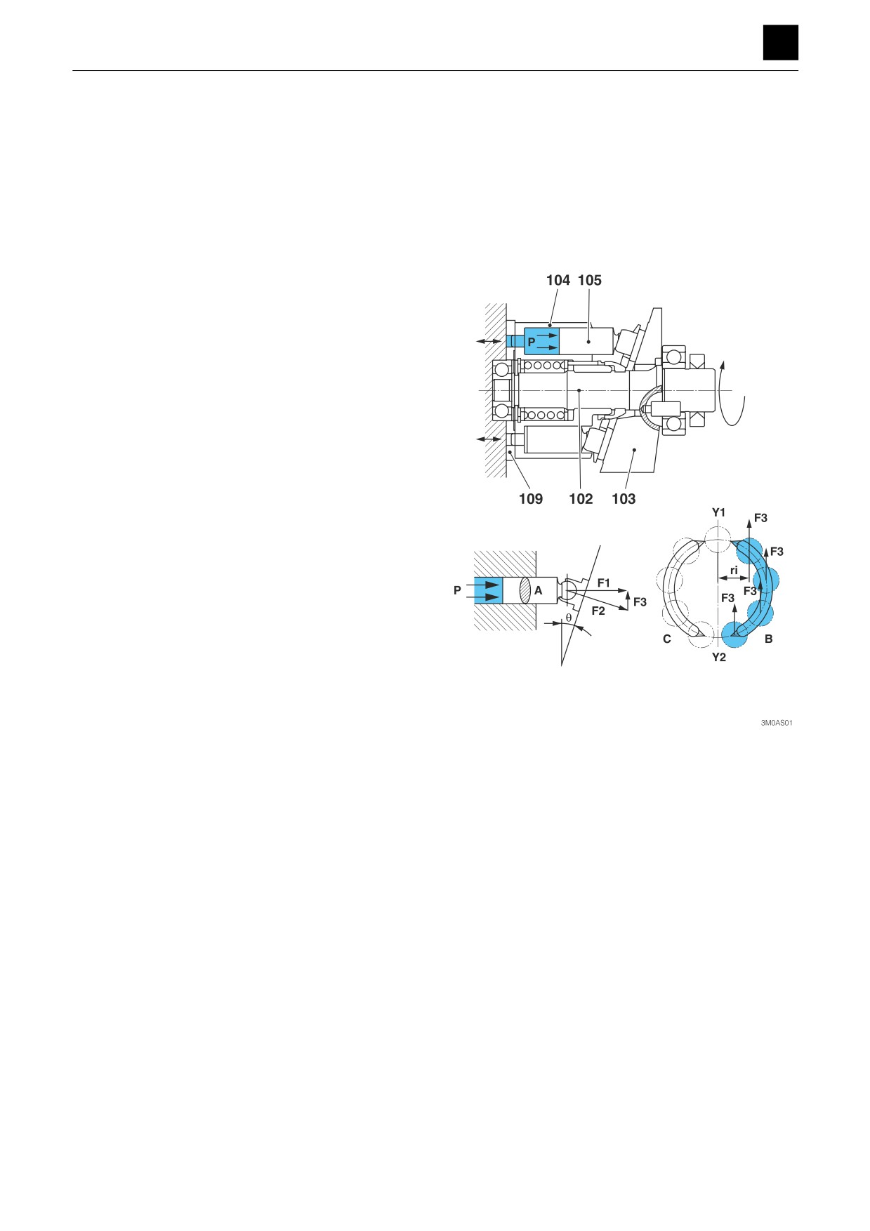
Hydraulic motor
The hydraulic motor is an axial piston motor with a
swashplate design. It converts the force of the pressure
oil transmitted from the pump into rotational movement.
The cylinder block (104) of the hydraulic motor is formed
of pistons (105), and its end surface comes in contact
with the valve plate (109), which contains the two cres-
cent-shaped ports B and C. The cylinder block (104) can
be rotated and is connected to the shaft (102) via the
spline.
The pressure oil supplied from the pressure oil pump is
injected into the cylinder block (104) through the valve
plate (109). At this time, the pressure oil is injected only
into one side (the port B side) connected to the bottom
dead center during a stroke of the pistons (105).
The pressure oil pushes on each piston (105) to generate
a force, F (=P×A), which acts on the angled surface of
the swashplate (103). The force F is split into two force
components F2 and F3 through the angle θ of the angled
surface, and the radial component F3 of these force
components produces a torque
(=F3×ri). The total
torque T (=∑(F3×ri)) of each piston (105) is used as the
rotational force that turns the hydraulic motor. This rota-
tional force turns the cylinder block (104) and the shaft
(102) via the pistons (105).
1
TRAVEL MOTOR
3M0AS00
FUNCTION
TRAVEL MOTOR 3
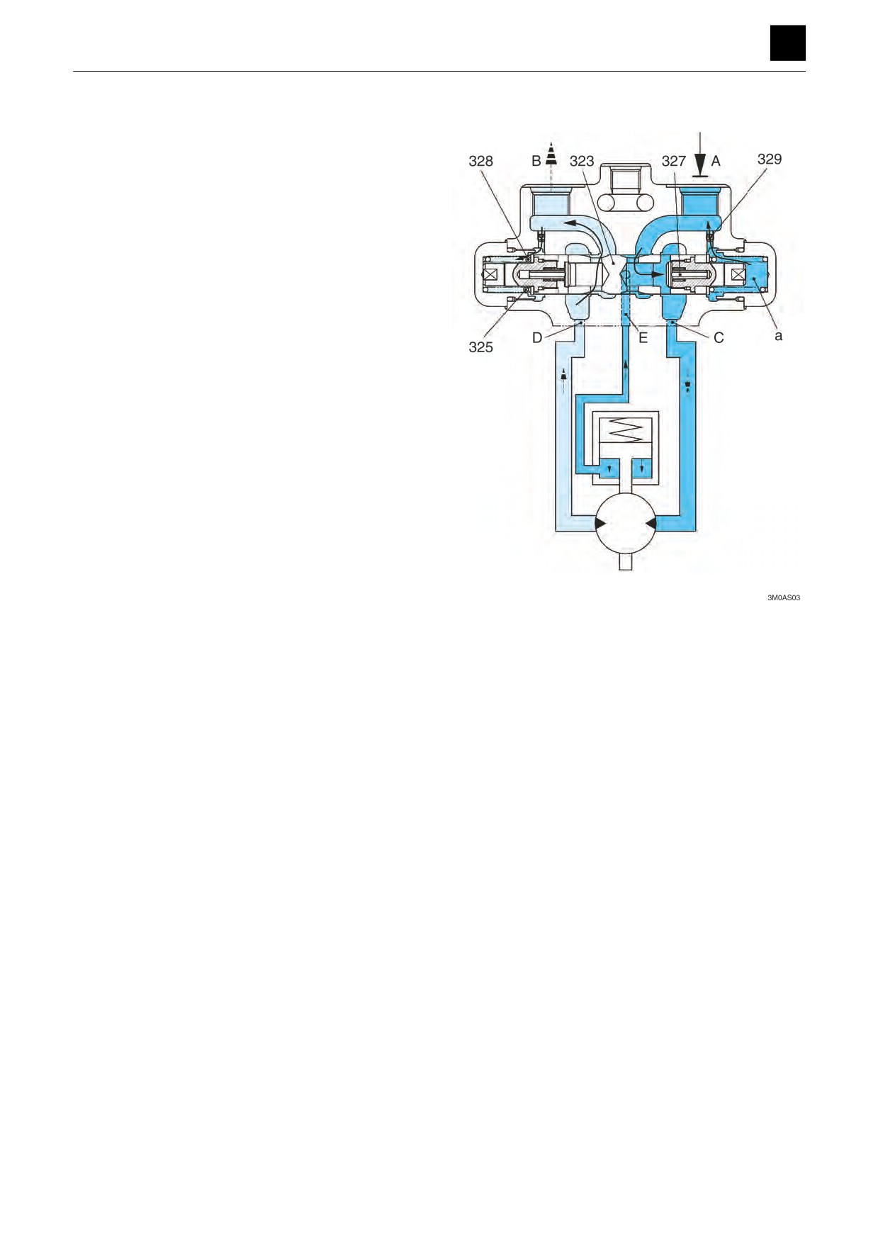
Brake valve
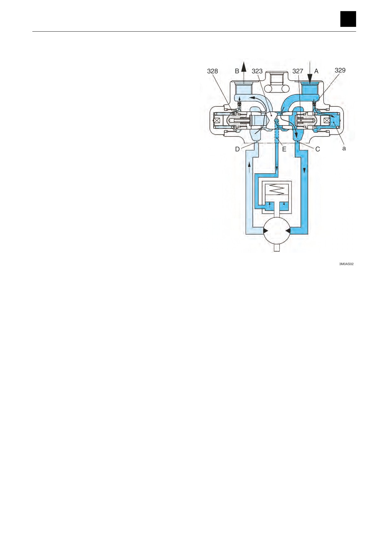
During normal operation
When pressure oil is supplied from port (A), the pressure
oil opens the valve (327), causing the oil to flow into port
(C) on the hydraulic motor inlet side, which works to turn
the hydraulic motor.
Simultaneously, the pressure oil enters the chamber (a)
from the orifice (329) and operates on the end surface of
the spool (323) to generate a force that causes the spool
(323), which is in a neutral position, to slide to the left by
the force of the spring (328).
Once the spool (323) has been slid, a gap (passage) is
formed between the spool (323) and the rear flange by
the groove in the spool.
This passage enables the return oil to return to the tank
side through the port (D) in the passage on the return
side of the hydraulic motor and through the port (B),
which enables the hydraulic motor to turn.
In addition, the pressure oil enters the port (E) due to the
sliding of the spool (323). The pressure oil that entered
the port (E) moves the piston of the parking brake and re-
leases the parking break.
For pressure oil supplied from the port (B), the spool and
valve move horizontally in reverse and rotate in reverse.
2
TRAVEL MOTOR
3M0AS00
FUNCTION
3
TRAVEL MOTOR
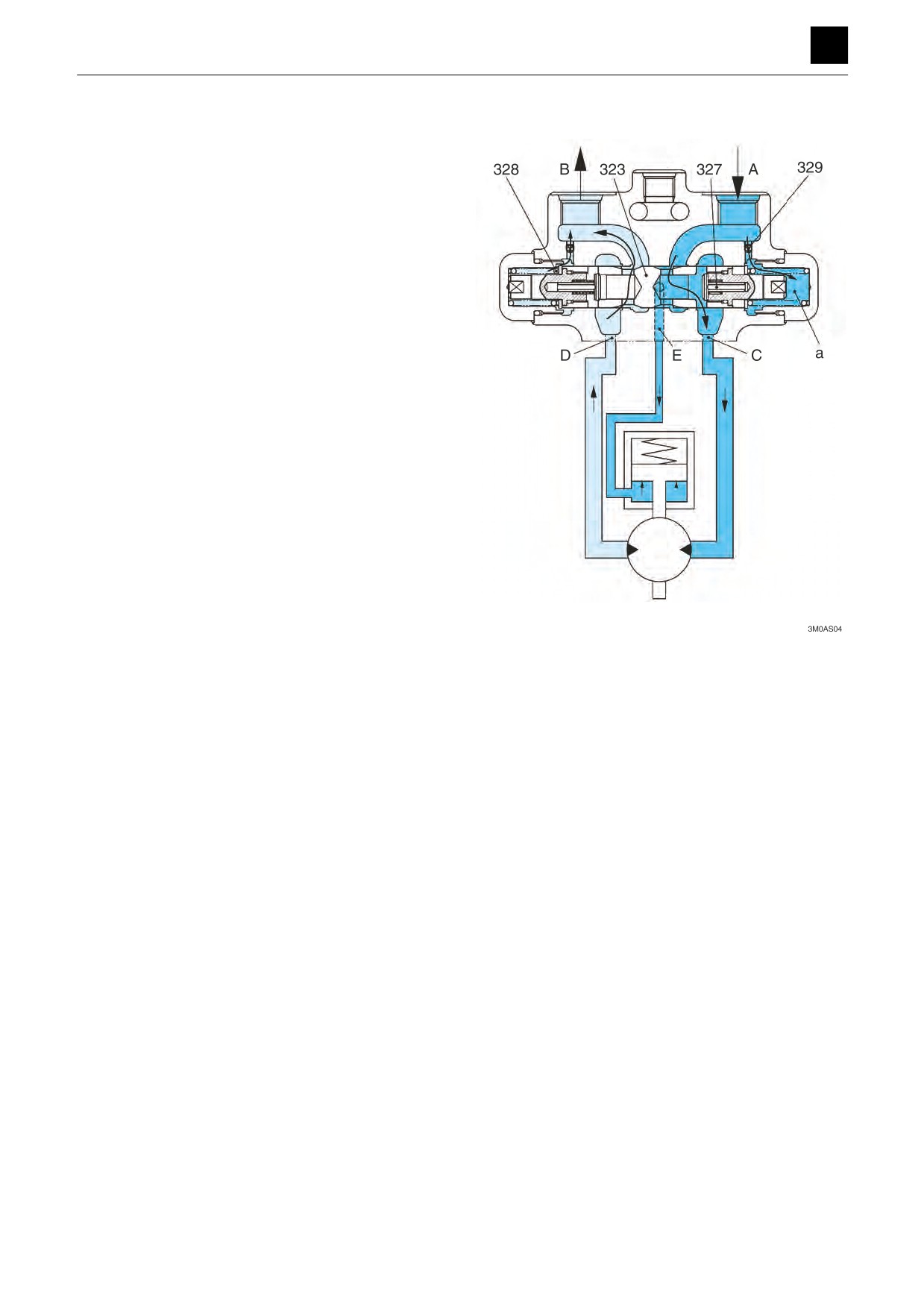
Stop operation (Braking operation)
When the supply of oil from the port (A) stops during trav-
el operation, the oil pressure pushing against the spool
(323) is eliminated, and the spool (323) that was slid to
the left attempts to return to the neutral position through
the washer (325) using the force from the spring (328).
At this time, the oil in the chamber (a) attempts to flow to
the port (A) side through the orifice (329), but a back
pressure is generated due to effects of the opening cre-
ated in the orifice (329), which works to control the return
speed of the spool (323).
Simultaneously, the hydraulic motor attempts to continue
rotating due to the influence of inertia, even after the sup-
ply of oil has stopped, which causes the return oil for the
hydraulic motor to attempt to return to the port (B) side
from the port (D) and through the gap (passage) be-
tween the spool groove and the rear flange.
Once the spool (323) returns all the way to the neutral po-
sition, the passage on the hydraulic motor return side is
completely shut off by the spool (323), causing the hy-
draulic motor to stop.
During operation, this brake valve controls the sliding
speed of the spool (323) and shape of the spool groove
used to close the passage on the hydraulic motor return
side, which enables the hydraulic motor to be smoothly
brought to a stop while it tries to rotate due to the inertial
force produced by the generated backpressure.
Meanwhile, when the hydraulic motor attempts to stop
due to braking, inertia causes the pump to continue ro-
tating and operating to attempt to absorb oil even after
the supply of pressure oil is shut off.
However, the passage on the suction side is blocked off
by the spool (323) so that the oil cannot be refilled, which
causes cavitation to begin to form.
At this time, the valve (327) operates under a slight neg-
ative pressure to open the oil pressure circuit between
the circuit on the port (A) side and the port (C) of the mo-
tor suction vent, which prevents cavitation from forming
in the hydraulic motor.
If the pressure oil is supplied from the port (B), the move-
ment of each of the aforementioned parts becomes sym-
metrical, which causes the motor to stop.
3
TRAVEL MOTOR
3M0AS00
FUNCTION
3
TRAVEL MOTOR
Function to prevent out-of-control operation
If the hydraulic motor begins rotating due to an external
force, the machine may begin operating uncontrollably
(run out of control) during operation at normal tempera-
ture. This could occur when the driver is trying to go
down a steep incline, for example.
An explanation of the mechanism used to prevent uncon-
trollable operation (out-of-control operation) is provided
here.
The hydraulic motor begins rotating due to an external
force during operation at normal temperature. The pres-
sure in the port (A) or port (B) supplying operating oil
drops.
When the pressure rises toward the level at which the
machine operates uncontrollably, the spool (323) begins
moving toward the neutral position.
Tthe size of the area of the passage for the oil from the
port (D) on the hydraulic motor outlet port side to the port
(B) decreases along with the travel distance of the spool
(323).
This limits the flow rate for the operating oil discharged
from the port (D) to the port (B).
The pressure (backpressure) in the port (D) increases at
the same time.
This controls the flow rate and pressure of the hydraulic
motor outlet port, which works to prevent uncontrolled
machine operation.
4
TRAVEL MOTOR
3M0AS00
FUNCTION
TRAVEL MOTOR 3
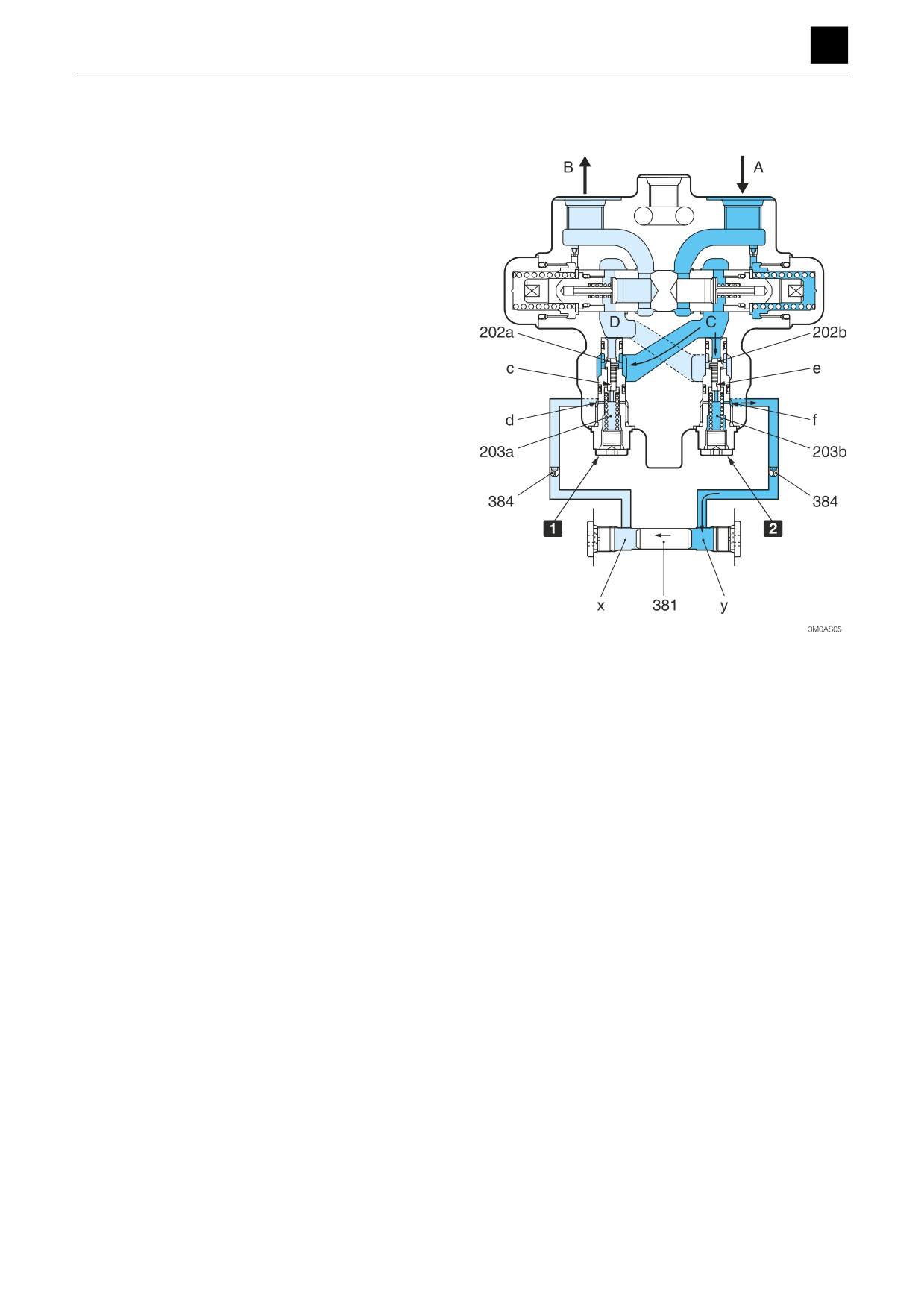
Explanation of relief valve operation
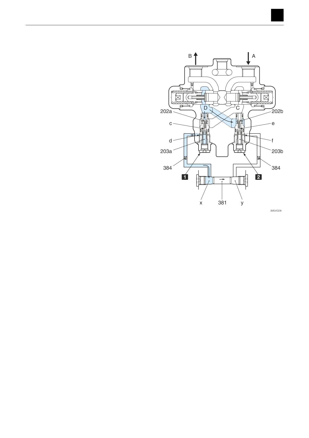
At startup
The pressure oil supplied from the pump flows from port
(A) to port (C).
Port (C) is connected to the hydraulic motor, and the
pressure oil that flows into port (C) exerts a rotational
force on the hydraulic motor.
At this time, in the relief valve (A), the valve (202a) does
not open through operation with the pressure oil.
In the relief valve (B), the valve (202b) is opened by the
pressure oil from port (C) when a pressure exceeding a
given level is exerted, and the pressure oil flows into port
(D).
The pressure oil from port (C) flows through the opening
(e) in the valve (202b), the opening (f) in the sleeve
(203b), and the orifice (384) into the chamber (y).
This pressure oil that flowed into the chamber (y) causes
the piston (381) to move to the stroke end in the direction
of the arrow.
When the piston (381) reaches the stroke end, the pres-
sure between the opening (e) in the valve (202b) and the
opening (f) in the sleeve (203b) increases.
The release pressure in the relief valve (B) increases to a
value about the system pressure of the shovel due to the
increase in pressure of the pressure oil, which causes
the valve (202b) to become closed.
The pressure of the port (C) increases and exerts a rota-
tional force on the motor due to the operation of the relief
1
Relief valve A
valve (A) and relief valve (B).
2
Relief valve B
5
TRAVEL MOTOR
3M0AS00
FUNCTION
TRAVEL MOTOR 3
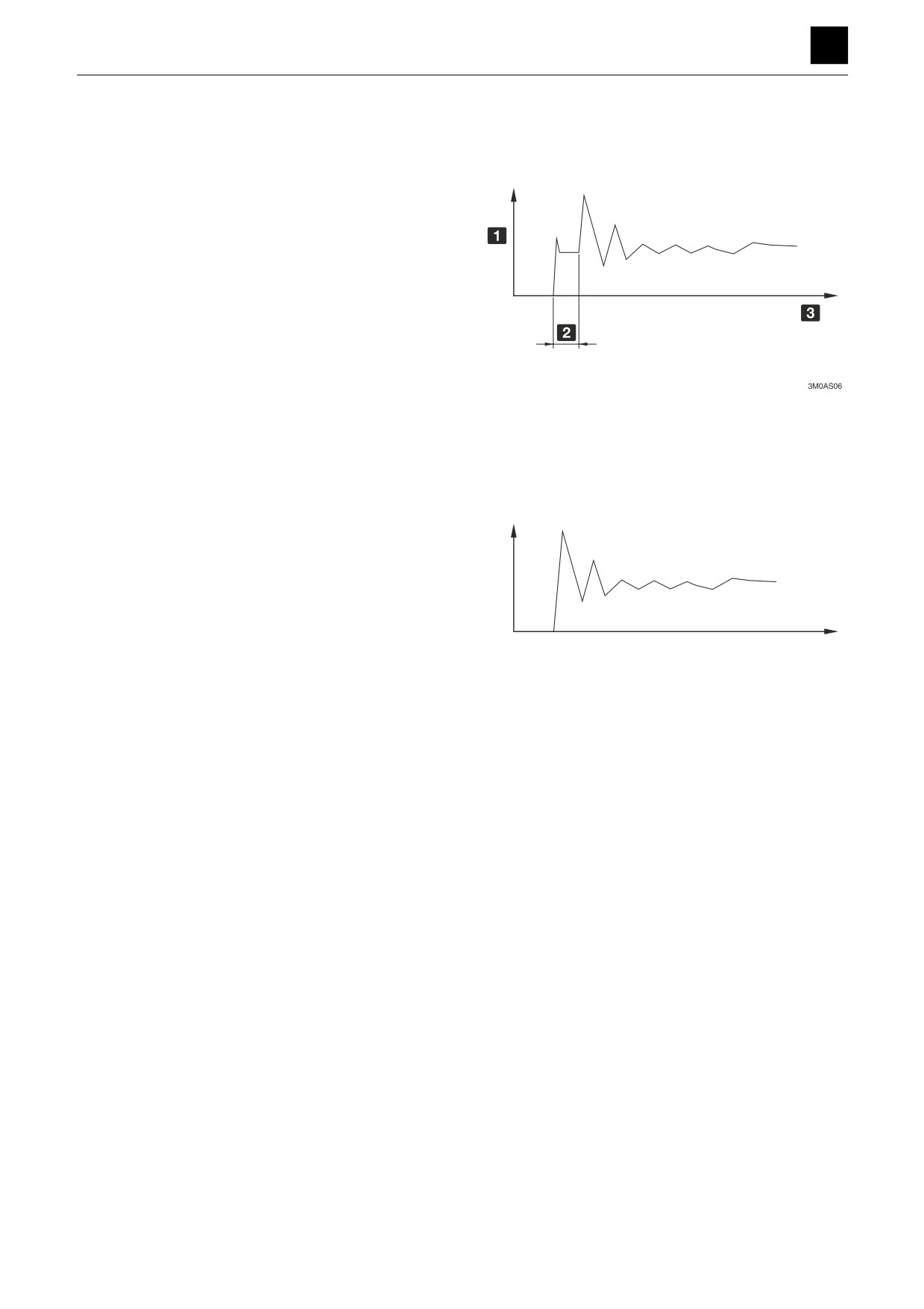
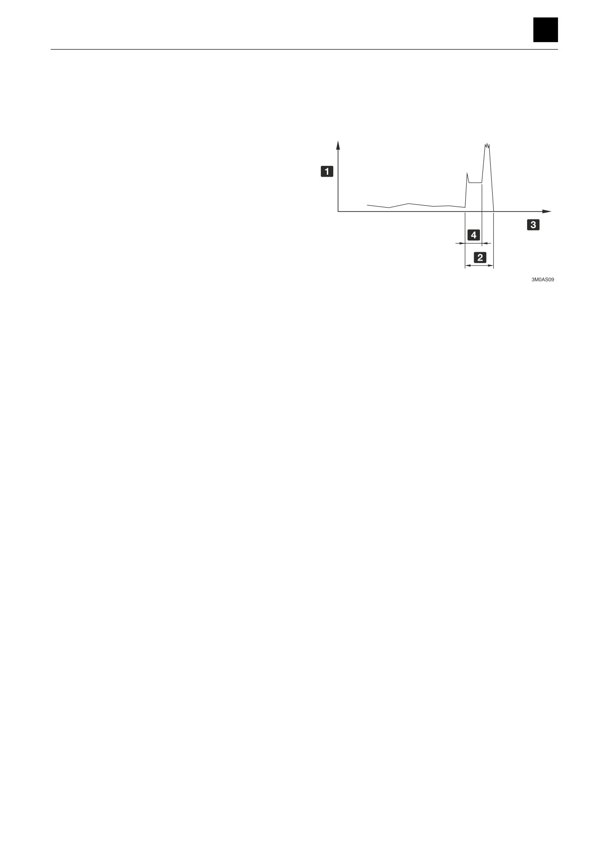
Pressure conditions in port (C) during the operation de-
scribed above
However, depending on the condition of the machine im-
mediately before it stops, the valve (202b) of the relief
valve (B) may not open if the piston (381) has reached
the stroke end.
The resultant pressure acting on the port (C) in this case
is described below.
1 Pressure
2 Release of relief valve B
3 Time
As described above, the pressure of the port (C) at start
up varies depending on the position of the piston (381).
The following is an example substituting the relief valve
(B) for the relief valve (A) in the above description of op-
1
erating principles for when the pressure oil supplied from
the pump flows from the port (B) to the port (D).
3
3M0AS07
1 Pressure
3 Time
6
TRAVEL MOTOR
3M0AS00
FUNCTION
3
TRAVEL MOTOR
During shutdown
When the supply of oil to the port (A) for the hydraulic mo-
tor, which rotates from the supply of pressure oil from the
port (A) to the port (C), is depleted, the counterbalance
valve returns to the neutral position.
When the counterbalance valve returns to neutral, the
port (D) on the outlet port side is shut off, causing the
pressure within the port (D) to increase due to the rota-
tion of the hydraulic motor according to the amount of in-
ertia.
The pressure oil inside the port (D) flows through the
opening (c) in the valve (202a), the sleeve (203a), and
the orifice (384) and into the chamber (x) in the relief
valve (A).
The pressure oil that flowed into the chamber (x) causes
the piston (381) to move to the stroke end in the direction
of the arrow.
The pressure in the chamber (x) does not increase while
the piston (381) is being moved.
This causes the valve (202a) of the relief valve (A) to be
pushed open by the pressure oil in the port (D), resulting
in the pressure oil from the port (D) flowing into the port
(C) on the low-pressure side.
The relief valve (A) operates to control the pressure in the
port (D) and supply oil to the port (C), which works to pre-
vent cavitation.
When the piston (381) reaches the stroke end, the pres-
sure between the chamber (x) and the opening (b) in the
1
Relief valve A
valve (202a) and opening (c) in the sleeve (203a) in-
3
Relief valve B
creases, causing the valve (202a) to close.
In this case, the relief valve (A) works to relieve the sys-
tem pressure and stop the hydraulic motor.
7
TRAVEL MOTOR
3M0AS00
FUNCTION
TRAVEL MOTOR 3
Pressure conditions in the hydraulic motor (port (D))
when the pressure oil supply described above is
stopped
The pressure while the piston (381) is moving is referred
to as the primary relief pressure (low pressure).
The pressure after the piston (381) has stopped moving
is referred to as the secondary relief pressure (high pres-
sure).
1 Pressure
2 Release of relief valve B
3 Time
4 While piston “d” is moved
8
TRAVEL MOTOR
3M0AS00
FUNCTION
TRAVEL MOTOR 3
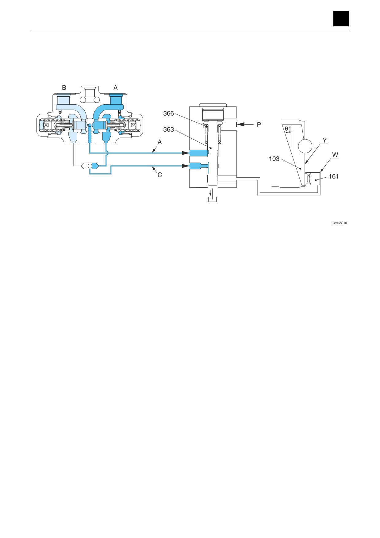
Automatic 2-speed switching mechanism
At low speed
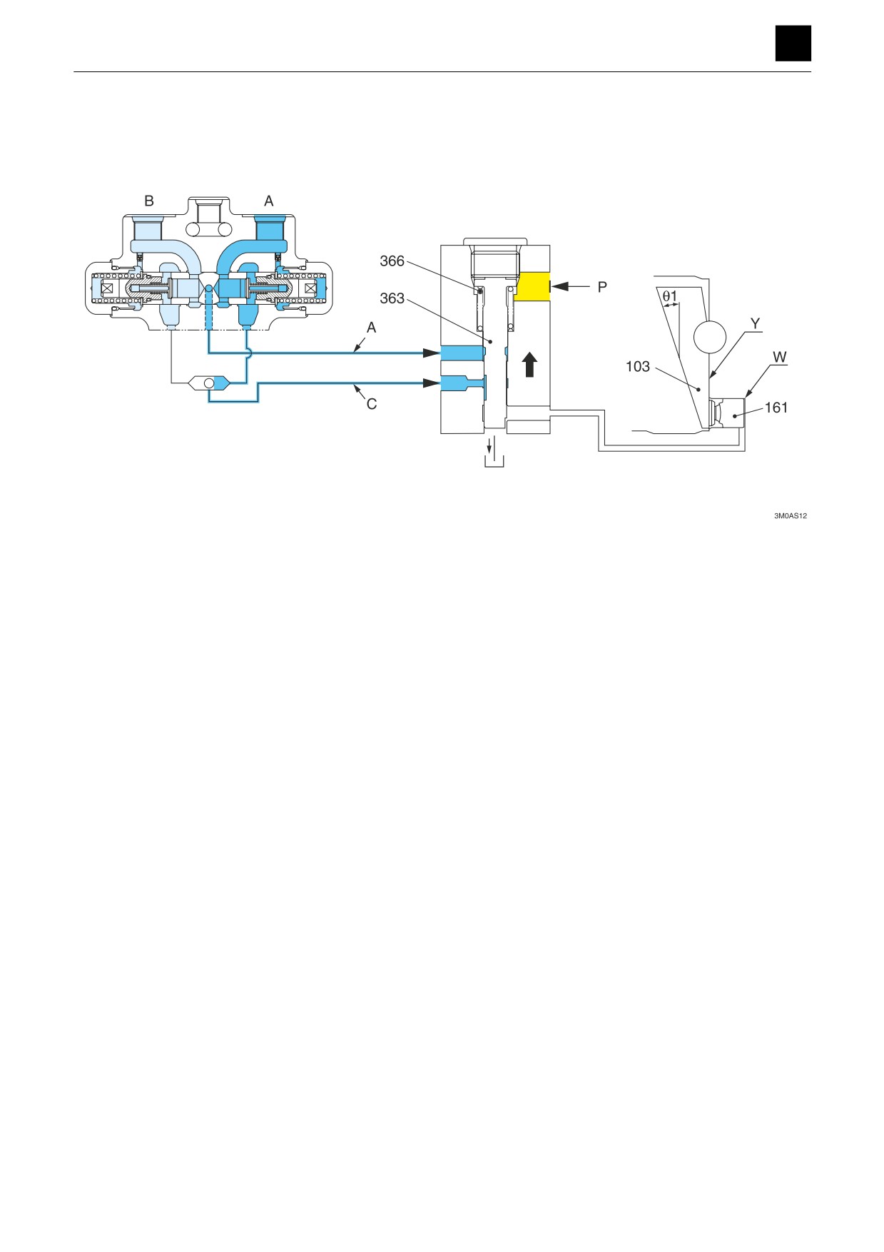
If there is no pilot pressure supplied from the port (P), the
valve (363) is pushed upward by the force of the spring
(366) and the pressure oil from the port (A) or port (B).
The pressure oil from (C) is blocked, and the oil from the
chamber (W) is released into the drain (motor case) via
the valve (363).
As a result, the angle of inclination of the swashplate
(103) increases to the maximum angle θ1, which causes
the displacement of the hydraulic motor to be maximized
and rotation to proceed at low speed.
9
TRAVEL MOTOR
3M0AS00
FUNCTION
TRAVEL MOTOR 3
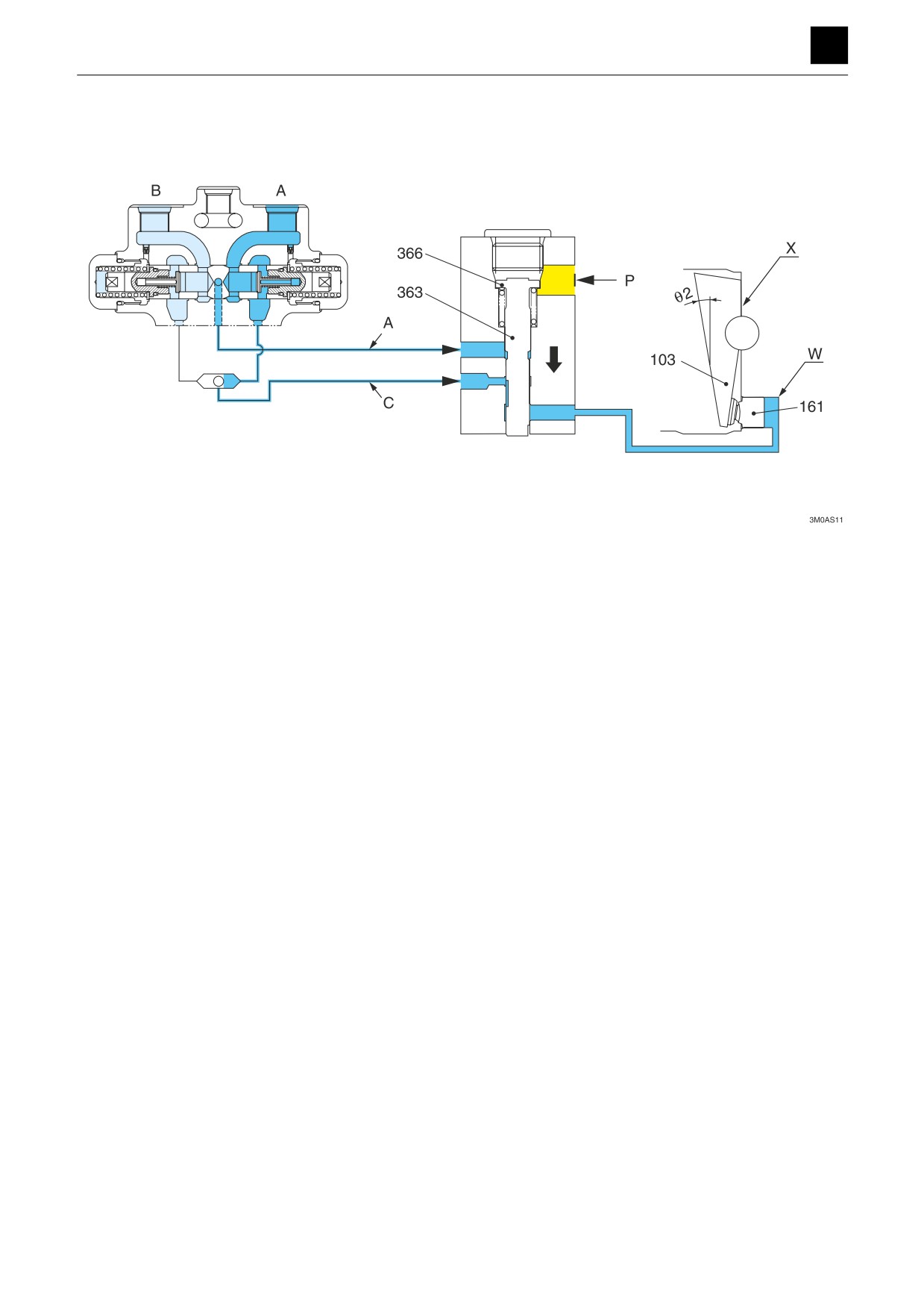
At high speed
If there is a pilot pressure supplied from the port (P), the
pilot pressure overcomes the force of the spring (366)
and the pressure oil from the port (A) or port (B) and
pushes the valve (363) downward, which causes the
pressure oil from the port (C) to flow into the chamber (W)
via the valve (363).
The piston (161) pushes the swashplate (103) downward
until it makes contact with the surface (X) and held at that
position.
At this time, the swashplate (103) is positioned at the
minimum angle of inclination θ 2, which causes the dis-
placement of the hydraulic motor to be minimized and ro-
tation to proceed at high speed.
10
TRAVEL MOTOR
3M0AS00
FUNCTION
TRAVEL MOTOR 3
Automatic switching to low speed during high-speed op-
eration
If the size of the load increases during high-speed oper-
ation, the pressure of the pressure oil in port (A) or port
(B) also increases, and when the pressure reaches a
specified value, the pressure overcomes the pilot pres-
sure of the port (P) and pushes the valve (363) upward.
The oil in the chamber (W) is released to the drain (motor
case) via the valve (363).
At this time, the swash plate (103) is pressed against the
surface (Y) and maintains a maximum angle of inclination
of θ1 in low-speed rotation.
11
TRAVEL MOTOR
3M0AS00
FUNCTION
TRAVEL MOTOR 3
Parking brake
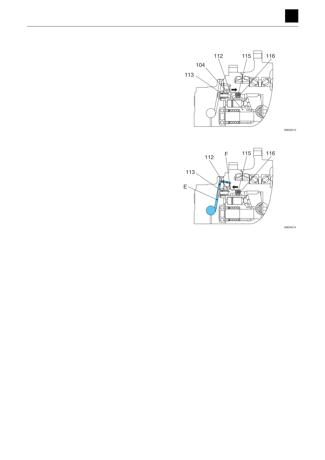
The parking brake works to prevent the hydraulic motor
from rotating due to an external force exerted while the
hydraulic motor is stopped. The parking brake uses a
friction disc braking mechanism and is formed together
with the hydraulic motor as one piece.
The friction disc (115) and the disc (116) of the hydraulic
motor are connected through the spline. The friction disc
(115) and the disc (116) are pressed against the spindle
by the springs (113) via the brake piston (112). The fric-
tion force between these discs generates a braking
torque that prevents the cylinder block (104) from rotat-
ing.
When the pressure oil is introduced into the motor, the
pressure oil flows from the parking brake release port (E)
into the brake piston chamber (F). The oil pressure over-
powers the spring force and moves the brake piston
(112) to the left. This creates a clearance between the
friction disc (115) and the disc (116), which releases the
parking brake function.
When the motor is stopped, the pressure oil from the
parking break release port is blocked, which causes the
springs (113) to generate a parking brake force.
12
TRAVEL MOTOR
3M0AS00
FUNCTION
3
TRAVEL MOTOR
Reduction gears
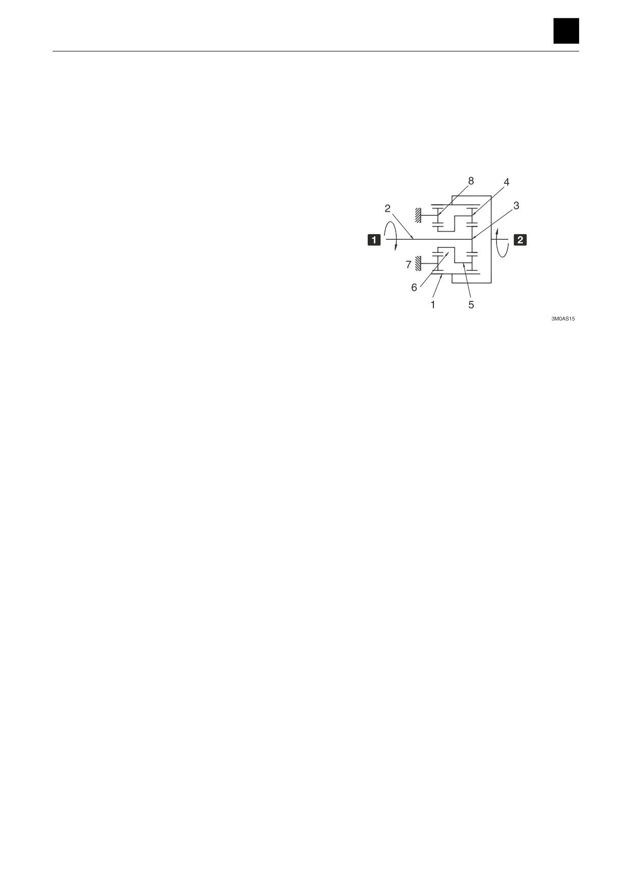
The reduction gears are formed of a 2-stage planetary
gear system that works to slow down the high-speed ro-
tational movement from the hydraulic motor and converts
it to a low-speed, high torque.
The reduction gears of the hydraulic motor are formed of
a 2-stage planetary gear system that works to convert the
high-speed rotational movement from the hydraulic mo-
tor into a low-speed, high torque and use the torque to ro-
tate the hub (1).
The rotational movement of the hydraulic motor axis is
transmitted to the 1st-stage sun gear (3) connected to
the spline in the shaft (2). At this stage, the 1st-stage
planetary gear (4) is meshed with the sun gear (3) and
meshes with the hub (1) to move in orbital motion while
rotating.
The orbital motion rotates the gear (5) affixed to the plan-
etary gears (4) as well as the 2nd-stage sun gear (6) con-
nected to the gear (5).
1
Input
This rotation is transmitted to the hub (1) (ring gear) via
2
Output
the 2nd-stage planetary gears (8) affixed to the support
column of the spindle (7) and produces the output rota-
tion of the reduction gears. The rotation is transmitted
from the 1st-stage planetary gears (4).
13
TRAVEL MOTOR
3M0AS00
FUNCTION
SLEW MOTOR 3
SLEW MOTOR
This section includes descriptions of the hydraulic motor
driven by hydraulics, the relief valve, the make-up valve,
the parking brake, the timer valve, and the reduction
gears.
Hydraulic motor
3
2
1
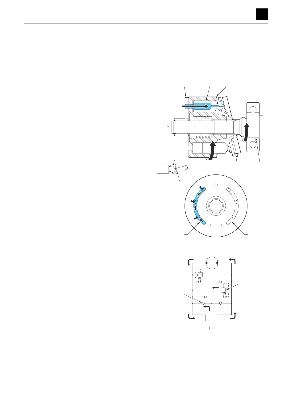
The cylinder block (1) is formed of pistons (2), and its end
surface comes in contact with the valve plate (3), which
contains two half-moon-shaped ports B and C. The cylin-
der block (1) rotates freely and is connected to the shaft
(4) via the spline. Meanwhile, the swashplate (5) is se-
cured to the housing.
When the high-pressure oil is made to flow into port B, the
A
pistons (2) push the swashplate (5) with a force F per pis-
ton (2).
F = P x A, P: Pressure, A: Cross-sectional area of piston
The force F used to push the swashplate (5) by the pis-
tons (2) is divided into two components: a force F1 that
pushes against the plate and a force F2 that rotates the
F1
cylinder block (1). The total sum of the components in the
F2
5
4
direction of rotation of the high-pressure side piston
F
works to generate a rotational force in the cylinder block
F
(1), and the torque is transmitted via the spline to the
shaft (4) to turn it. Conversely, if high-pressure oil is intro-
duced into the port C, the rotation occurs in the direction
F2
opposite that of the above.
F
F2
B
C
3N0AQ01Z
Relief valve
The relief valves are used to set the driving force and
braking force during slew operation of the machine, with
each having main port A, B lines and each being formed
of a circuit in which the relief valve return oil returns to the
6
main low-pressure line on the opposite side through the
make-up valves. The relief valves also come equipped
7
with shockless functions that reduce the impact of
shocks generated at the start of acceleration.
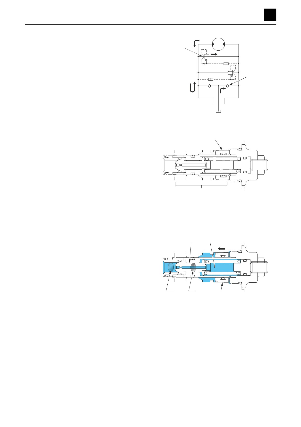
The inertial load at motor startup is fairly significant and
causes the oil pressure used for rotation to actually in-
B
T
A
crease. When this pressure reaches the set relief valve
3N0AQ02Z
pressure, the relief valve (6) turns on, and the oil opens
the make-up valve (7) and flows into the port B.
This type of motor starts rotating while activating the relief
valve (6), with the amount of relief oil decreasing to zero
as the number of rotations increases.
This allows shocks to be absorbed during startup.
1
SLEW MOTOR
3N0AS00
FUNCTION
SLEW MOTOR 3
When the motor stops, the return circuit closes. However,
the motor continues trying to rotate using the inertial en-
ergy, which causes the port B pressure to increase and
6
the port A to experience a negative pressure in contrast.
When the port B pressure reaches the set value for the
relief valve, the oil acts on the relief valve (6), which caus-
es the make-up valve (7) to open and the oil to flow into
7
port A.
With the oil flowing into the port A in this way, shocks from
stopping are absorbed while the formation of cavitation
is prevented.
B
T
A
3N0AQ03Z
Structure of the relief valve
Use of a shockless relief valve has the effect of reducing
the impact of shocks, reducing the amount of stress gen-
1
erated in strengthening support parts, and the like.
2
3N0AQ04Z
1 Direct-acting differential area relief valve
2 Shockless piston
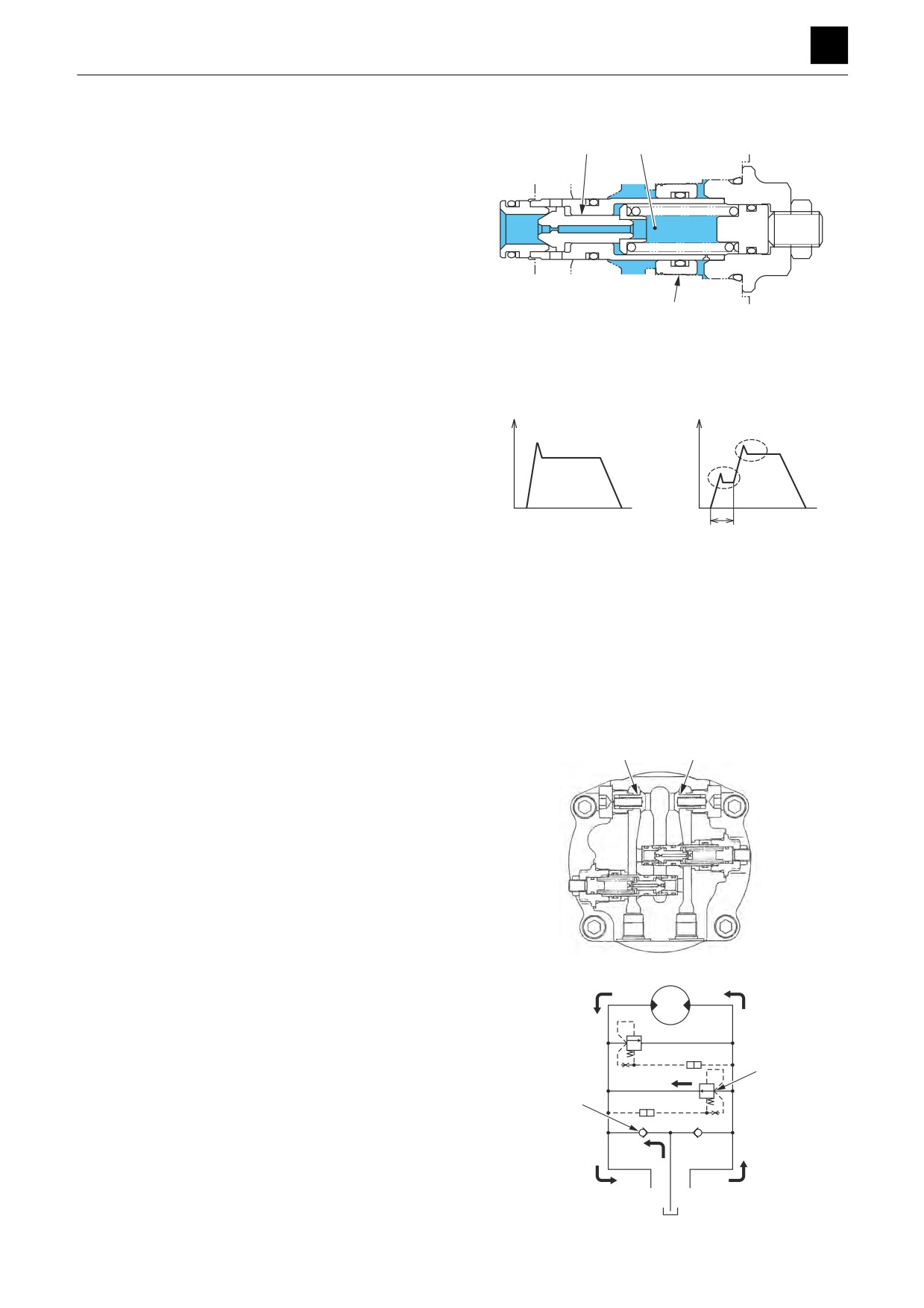
There are two stages in relief valve operation as listed
below.
1st-stage
10
9
At the beginning of operation, the shockless piston (8) is
moved, and a low pressure is maintained within the
spring chamber (9). For this reason, the area of the pop-
pet (10) affected by pressure is the poppet sheet area
(S1). The area affected by pressure is fairly large com-
pared to the area affected by pressure (S1-S2) during
regular relief setting. This allows the relief hydraulic pres-
S1
S2
sure to be maintained at a low value until the shockless
8
piston (8) finishes being moved.
3N0AQ05Z
2
SLEW MOTOR
3N0AS00
FUNCTION
SLEW MOTOR 3
2nd-stage
Once the shockless piston
(8) has stopped being
moved, the pressure inside the spring chamber (9) in-
10
9
creases and becomes equal to the pressure in front of
and behind the poppet (10). The relief valve is thus acti-
vated by the regular set pressure.
8
3N0AQ06Z
The diagram shows pressure waveforms for equipment
without shockless pistons and equipment with shockless
pistons.
3
3
4
4
5
1
2
3N0AQ07Z
1 Without shockless piston
2 With shockless piston
3 Pressure
4 Time
5 Region of shockless piston operation
Make-up valve
The make-up valve (7) has two different functions.
7
7
One of the functions is preventing cavitation occurring
due to the piston motor being overrun, which prevents
the slew body from running uncontrolled.
3N0AQ08Z
When the motor is turned using the inertial force of the
slew both to create a pumping action and the motor
speed in RPMs exceeds the speed in RPMs suitable for
the amount of oil supplied to the motor. Extra oil is sup-
plied from external to the main circuit of the motor via the
6
make-up valve (7) to make up for any lack of oil and to
prevent a vacuum from forming within the circuit.
7
B
T
A
3N0AQ02Z
3
SLEW MOTOR
3N0AS00
FUNCTION
SLEW MOTOR 3
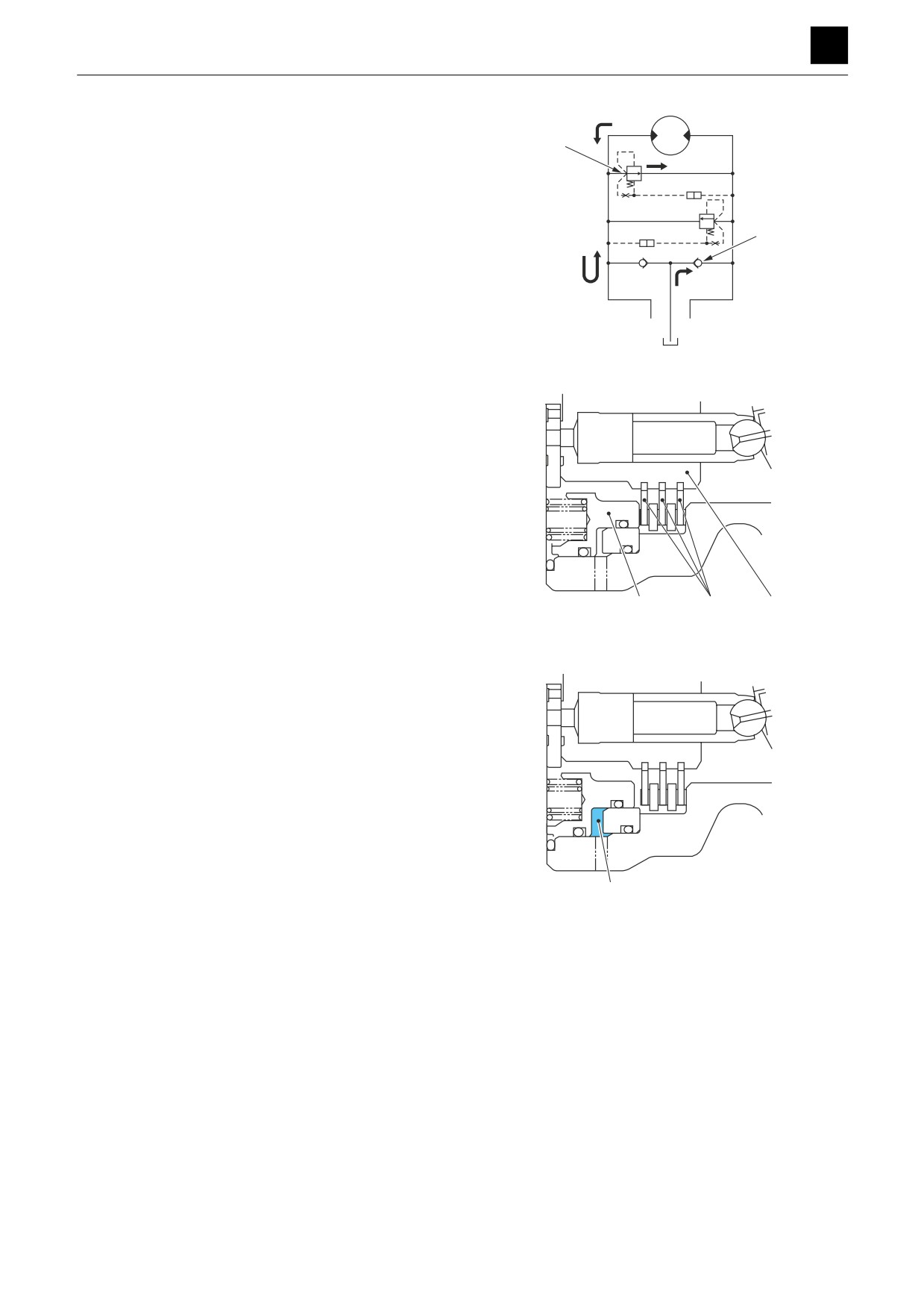
The other function is to prevent a vacuum from forming
inside the circuit through the supply of extra oil from the
make-up valve (7) to compensate for motor drain and
6
valve leaks to enable a braking function to be obtained
under normal circuit conditions when the circuit between
control valve and motor is closed off, as with the brake.
7
B
T
A
3N0AQ03Z
Parking brake
With the parking brake ON
The parking park has a hydraulic-release, multiple-disc
structure and a locking mechanism with a switching axis
that operates to turn the brake ON and OFF using exter-
nal signal pressure.
With the hydraulics for releasing the break shut off, the
disc (11) coupled with the spline in the outer periphery of
the cylinder block (1) pushes against the brake piston
(12) (which is stopped to prevent it from rotating) with the
spring force, causing the cylinder block (1) and case to
be immobilized together by a frictional force. This causes
12
11
1
3N0AQ09Z
the shaft to be locked in place.
When the brake-release pressure is supplied to the
brake cylinder chamber (13) through the port PB, the
brake piston uses the release pressure to overcome the
spring force, which cancels out the frictional force acting
on the disc and enables the shaft to rotate freely.
13
3N0AQ10Z
4
SLEW MOTOR
3N0AS00
FUNCTION
SLEW MOTOR 3
Timer valve
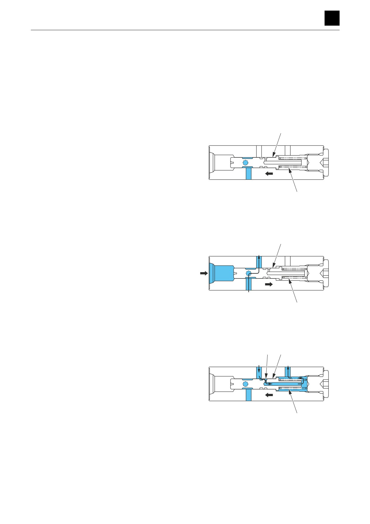
The timer valve is used to prevent the parking brake from
being pulled during slew parking. While the inertial slew
force is being absorbed by the dynamic hydraulic brake,
the timer valve has the role of working to secure a delay
time period during which the parking brake does not op-
erate, with the delay time being set by the opening in the
orifice from which the discharge oil discharges from the
brake cylinder chamber and by the flow rate.
While the parking brake is activated, the pilot pressure
continuously flows into the port PG, and the spool (14) is
14
shifted to the left position by the spring (15) force, which
causes the port PG to close.
dr
SH
PG
15
3N0AQ11Z
When the slew pilot pressure or arm pulling (CROWD) pi-
lot pressure is introduced into the port SH, the pilot pres-
14
sure overcomes the spring (15) force and moves the
spool to the right, causing the port PG to open.
PB
dr
The pressure oil in the port PG flows into the port PB for
releasing the parking brake through the center hole on
SH
the spool (14), which releases the parking brake func-
tion.
PG
15
3N0AQ12Z
If the pilot pressure in the port SH decreases to zero, the
spool (14) is moved to the left by the spring (15) force,
16
14
the port PG closes, and the oil in the brake cylinder
chamber is also shut off. The oil that is shut off slowly
dr
flows into the drain port dr from the orifice (16) in the pe-
riphery of the spool (14). This works as a timer that acti-
vates the parking brake after a certain amount of time so
SH
as to prevent sudden operation of the parking brake.
PG
15
3N0AQ13Z
5
SLEW MOTOR
3N0AS00
FUNCTION
SLEW MOTOR 3
Reduction gears
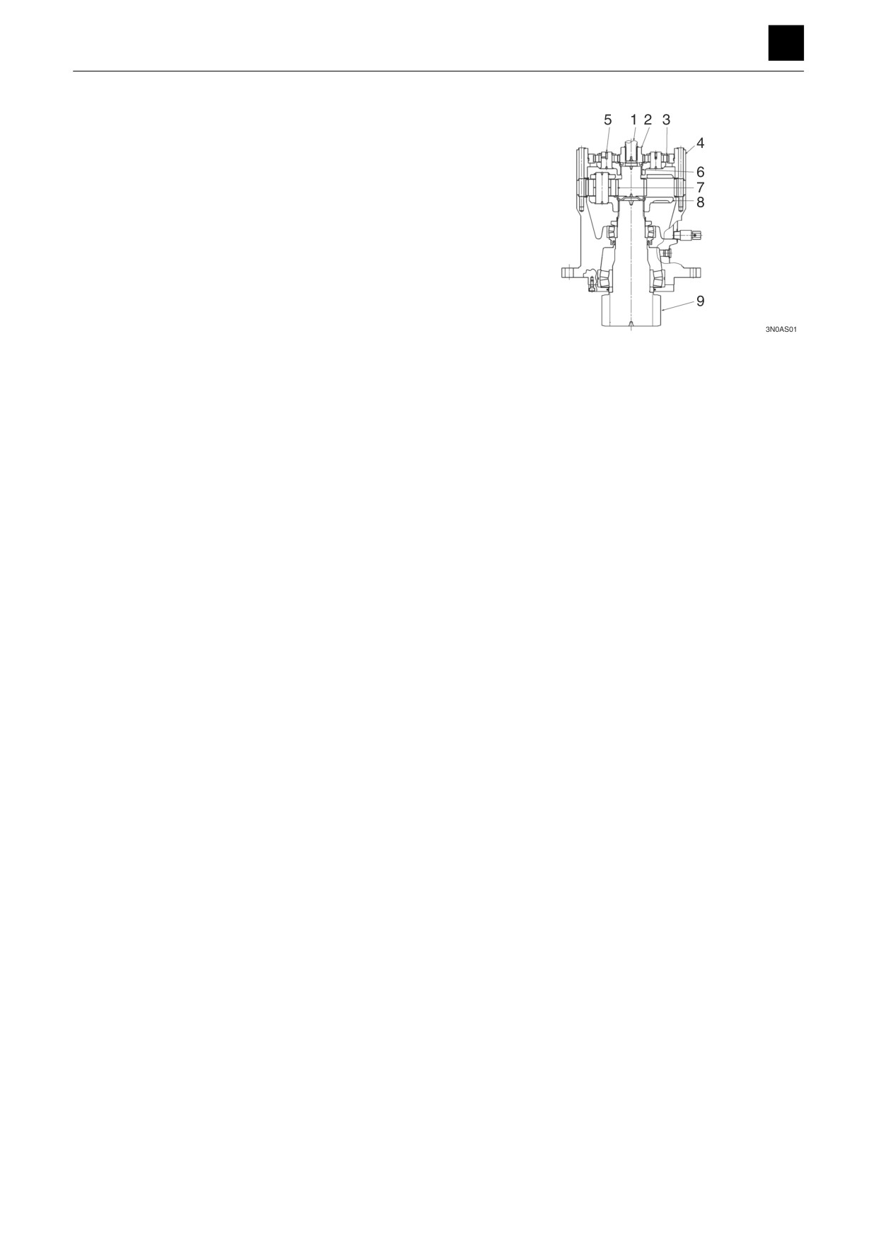
The motor shaft (1) connects the drive gear (2) and the
spline. The driving force of the hydraulic motor is trans-
mitted to the planetary gears (3) that are meshed with the
drive gear (2). The planetary gears (3) are meshed with
the ring gear in the reduction gear housing (4). This al-
lows the planetary gears to move in orbital motion along
the ring gear while rotating.
The planetary gears (3) are held in position via the bear-
ings in the holder (5), and the holder (5) transmits the or-
bital motion of the planetary gears (3) to the sun gear (6)
connected to the spline. The sun gear (6) meshes with
the planetary gears (7) and transmits the rotating motion
to the planetary gears (7) as in the first stage. The plane-
tary gears (7) mesh with the ring gear in the housing,
which allows them to move in orbital motion while rotat-
ing. The planetary gears (7) mesh with the ring gear in
the housing, which allows them to move in orbital motion
while rotating. The planetary gears (7) are held in posi-
tion via the bearings in the holder (8), and the holder (8)
transmits the orbital motion of the planetary gears (7) to
the pinion shaft connected to the spline.
6
SLEW MOTOR
3N0AS00
FUNCTION
3
SWIVEL JOINT
SWIVEL JOINT
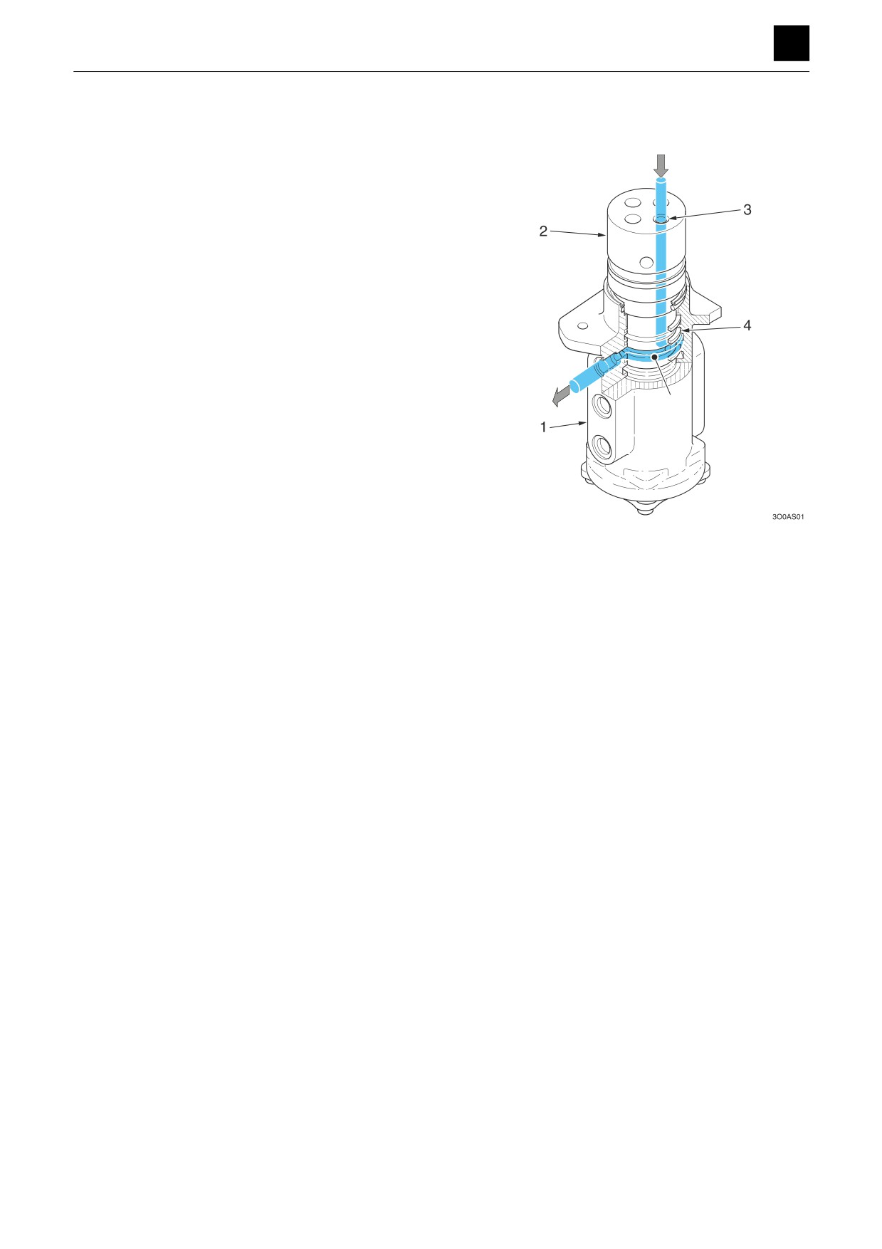
The swivel joint is located at the slew center of the ma-
chine and has the role of maintaining the connection to
the oil circuit regardless of the slew angle of the upper
frame.
A number of ports (3) equal to the number of fluid circuits
is provided on a hub (1) and shaft (2) that are mutually
rotatable. Grooves used as oil passages are processed
into the inner periphery of the hub (1) and the outer pe-
riphery of the shaft (2). A seal is applied to the top and
bottom of the peripheral grooves. The oil flowing from the
port (3) continues to flow through the oil pressure pas-
sage (5) between the hub (1) and shaft (2) to enable con-
tinued connection of the circuit located between the slew
assemblies without it being blocked due to rotation.
1
SWIVEL JOINT
3O0AS00
4
DISASSEMBLY AND ASSEMBLY
Service standards
Drive system
Travel system
Slew equipment
Upper frame
Operating device
Attachments
Hydraulic tank
Hydraulic pump (main)
Hydraulic pump (sub)
Control valve
Pilot valve
Pilot valve (swing, blade)
Pilot valve (travel)
Proportional control solenoid valve
Solenoid valve (dual-section)
Shockless valve
Cylinders
Travel motor
Slew motor
Swivel joint