Takeuchi Hydraulic excavator TB1140 (Serial No. 514400002~). Operator's Manual - page 2
SERVICE DATA
2
PERFORMANCE CRITERIA
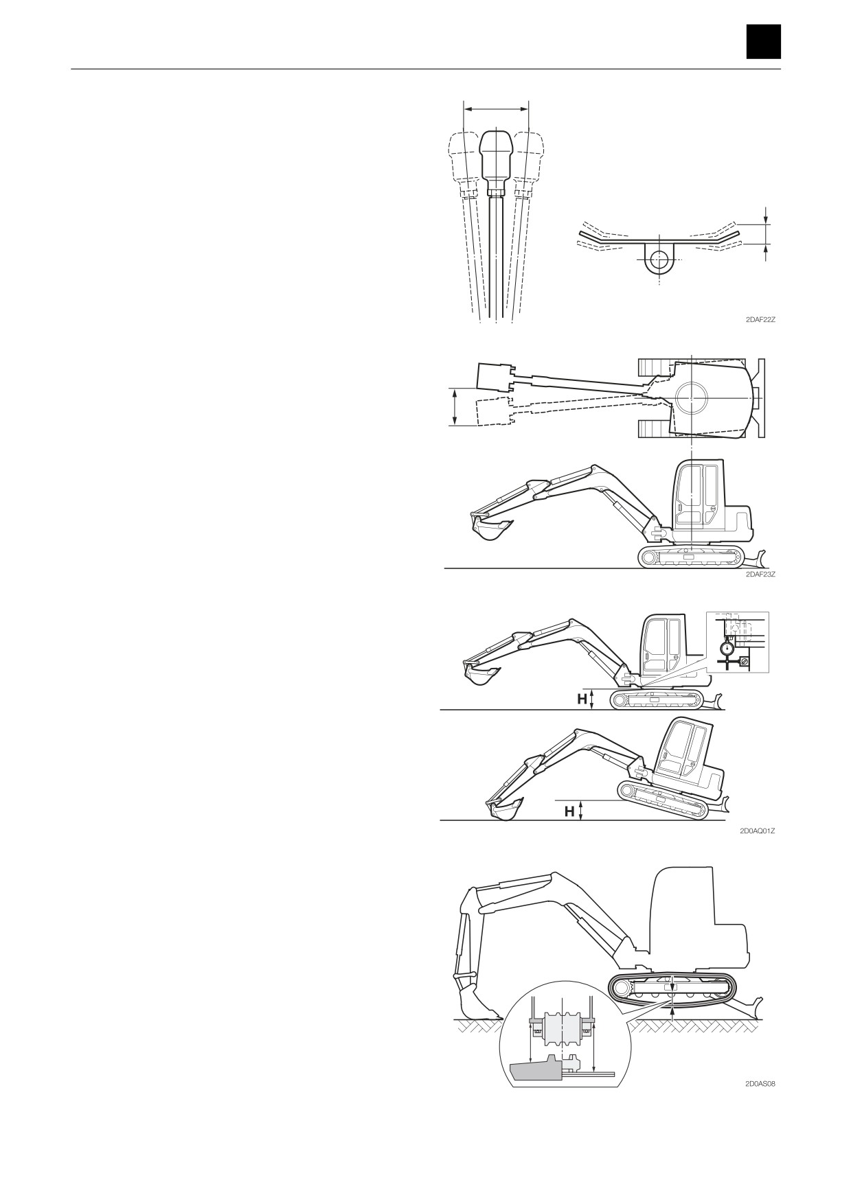
Lever play
• Measure any discernible play at the tip of the lever or
pedal.
Backlash
• Measuring attitude: Completely retract the arm cylin-
der, and fully extend the bucket cylinder.
• Move the tips of the bucket teeth from side to side (left
and right), and measure the amount of play.
Slew bearing play
1. With the bucket in a no-load state, completely retract
the arm cylinder, fully extend the bucket cylinder,
move the dozer blade back, and make adjustments
so that the boom foot pin and bucket pin are at the
same height.
2. Attach a dial gauge to the bottom face of the slew
bearing’s outer race located near the front of the ex-
cavator, and set the dial gauge to 0.
3. Lower the boom, raise the crawler to the height, H,
and then read the dial gauge to get the measure-
ment.
Track tension
• Measuring attitude: Excavator body to be raised using
both the hoe attachment and the dozer blade. For
models with rubber crawlers, line up the crawler seam
joint (marked with an M or symbol) with the upper cen-
ter of the upper structure.
• Measure the width of the gap between the bottom sur-
face of the frame and the top surface of the track shoe
at the center of the crawler frame.
12
PERFORMANCE CRITERIA
2D0AS00
SERVICE DATA
2
TIGHTENING TORQUE
TIGHTENING TORQUE
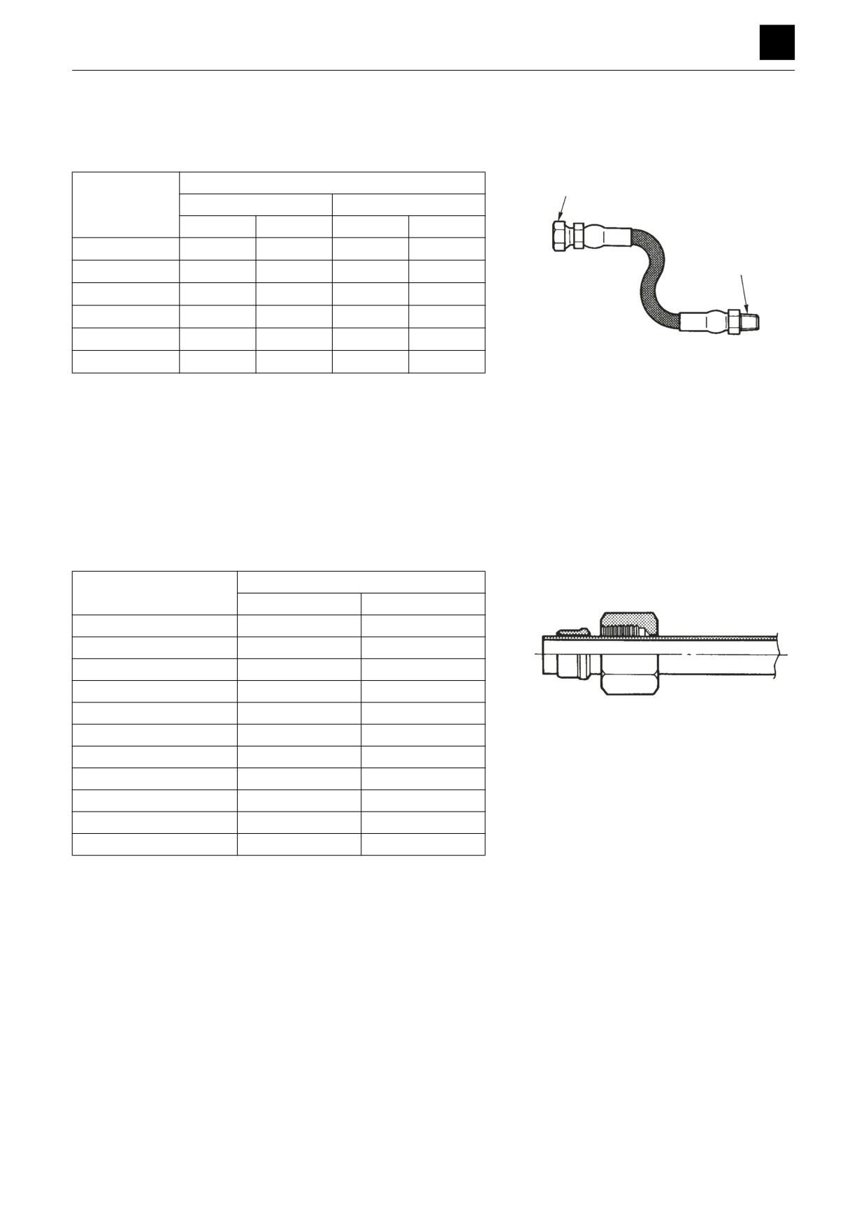
Hydraulic hose
UNION NUT
Tightening torque
ÜBERWURFMUTTER
ECROU D'UNION
Hose fitting size
Union nut (G)
Taper thread (R)
N·m
ft.-lb
N·m
ft.-lb
+4.9
+3.5
1/8
9.8
0
7.3
0
11.8 ± 1.2
8.7 ± 0.8
TAPER THREAD
KEGELWINDUNG
+4.9
+3.5
FILETAGE CONIQUE
1/4
24.5
0
18.1
0
29.4 ± 2.9
21.7 ± 2.1
+4.9
+3.5
3/8
49.0
0
36.2
0
53.9 ± 5.4
39.8 ± 3.9
58.8
+4.9
43.4
+3.5
1/2
0
0
88.3 ± 8.8
65.1 ± 6.4
+4.9
+3.5
2EAA01Z
3/4
117.7
0
86.8
0
147.1 ± 14.7
108.5 ± 10.7
137.3
+4.9
101.3
+3.5
1
0
0
196.1 ± 19.6
144.7 ± 14.3
Bite-type pipe fitting for steel pipe
Outer diameter of pipe
Tightening torque
(mm)
N·m
ft.-lb
8
34.3 ± 4.9
23.5 ± 3.5
10
41.7 ± 2.5
30.7 ± 1.7
12
58.8 ± 4.9
43.4 ± 3.5
15
88.3 ± 4.9
65.1 ± 3.5
16
93.2 ± 4.9
68.7 ± 3.5
18
132.4 ± 4.9
97.6 ± 3.5
2EAA02Z
22
205.9 ± 9.8
151.8 ± 7.2
27.2
245.2 ± 9.8
181.0 ± 7.2
28
313.8 ± 19.6
231.4 ± 14.3
32
313.8 ± 19.6
231.4 ± 14.3
35
411.9 ± 19.6
303.7 ± 14.3
1
TIGHTENING TORQUE
2E0AS00
SERVICE DATA
2
TIGHTENING TORQUE
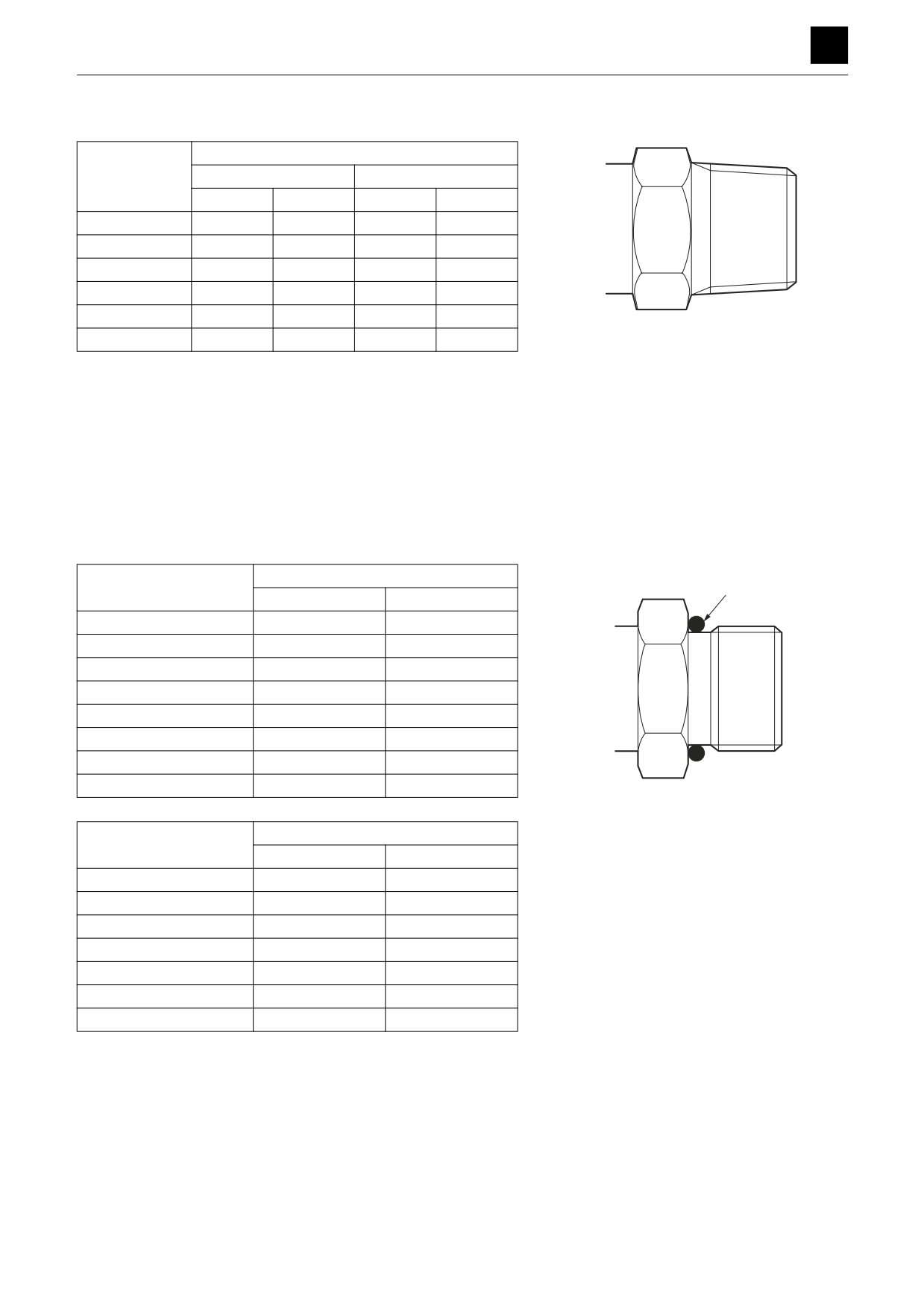
Joint for piping
Tightening torque
Nominal thread
Steel
Cast steel
diameter (R)
N·m
ft.-lb
N·m
ft.-lb
1/8
11.8 ± 1.2
8.7 ± 0.8
10.8 ± 1.1
8.0 ± 0.7
1/4
29.4 ± 2.9
21.7 ± 2.1
24.5 ± 2.5
18.1 ± 1.7
3/8
53.9 ± 5.4
39.8 ± 3.9
49.0 ± 4.9
36.2 ± 3.5
1/2
88.3 ± 8.8
65.1 ± 6.4
73.5 ± 7.4
54.3 ± 5.3
3/4
147.1 ± 14.7
108.5 ± 10.7
127.5 ± 12.7
94.1 ± 9.3
2EAA03Z
1
196.1 ± 19.2
144.7 ± 14.3
171.6 ± 17.2
126.6 ± 12.5
Joint for piping (O-ring seal type)
O-RING
Nominal thread diameter
Tightening torque
O-RING
JOINT TORIQUE
(G)
N·m
ft.-lb
1/8
19.6 ± 2.0
14.5 ± 1.4
1/4
34.3 ± 4.9
25.3 ± 3.5
3/8
53.9 ± 4.9
39.8 ± 3.5
1/2
63.7 ± 4.9
47.0 ± 3.5
3/4
93.2 ± 4.9
68.7 ± 3.5
1
107.9 ± 9.8
79.5 ± 7.2
1-1/4
117.7 ± 9.8
86.8 ± 7.2
2EAA04Z
1-1/2
137.3 ± 9.8
101.2 ± 7.2
Nominal thread diameter
Tightening torque
(UNF)
N·m
ft.-lb
7/19-20
16.7 ± 2.0
12.3 ± 1.4
1/2-20
22.6 ± 2.0
16.6 ± 1.4
9/16-18
31.4 ± 2.9
23.1 ± 2.1
3/4-16
59.8 ± 4.9
44.1 ± 3.5
1-1/16-12
102.0 ± 5.9
75.2 ± 4.4
1-5/16-12
135.3 ± 7.8
99.8 ± 5.8
1-5/8-20
181.4 ± 9.8
133.8 ± 7.2
2
TIGHTENING TORQUE
2E0AS00
SERVICE DATA
2
TIGHTENING TORQUE
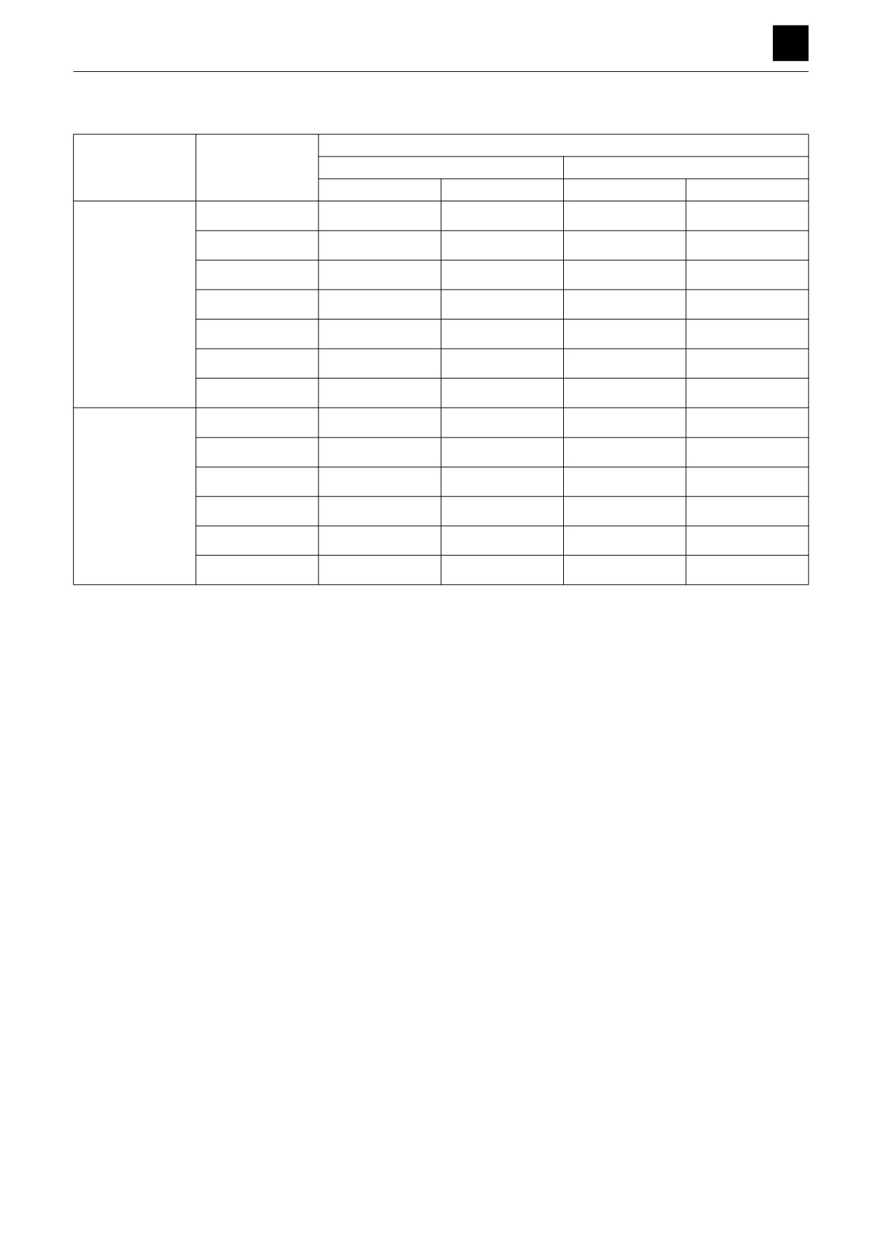
Bolts and nuts (JIS strength category 10.9)
Tightening torque
Thread
Size × pitch
General tightening points
Special tightening points
N·m
ft.-lb
N·m
ft.-lb
M6 × 1.0
9.8 ± 0.5
7.2 ± 0.4
11.8 ± 1.1
8.7± 0.4
M8 × 1.25
22.6 ± 1.1
16.6 ± 0.8
26.5 ± 2.5
19.5 ± 0.9
M10 × 1.5
47.1 ± 2.4
34.7 ± 1.7
54.9 ± 4.9
40.5 ± 2.0
Coarse
M12 × 1.75
83.4 ± 4.1
61.5 ± 3.0
97.1 ± 7.4
71.6 ± 3.5
M14 × 2.0
134.4 ± 6.7
99.1 ± 4.9
155.9 ± 12.7
115.0 ± 5.7
M16 × 2.0
207.9 ± 10.4
153.3 ± 7.7
241.2 ± 17.2
177.9 ± 8.9
M20 × 2.5
410.9 ± 20.5
303.1 ± 15.1
475.6 ± 23.7
350.8 ± 17.5
M8 × 1.0
24.5 ± 1.2
18.1 ± 0.9
28.4 ± 1.4
21.0 ± 1.0
M10 × 1.25
50.0 ± 2.5
36.9 ± 1.8
58.8 ± 2.9
43.4 ± 2.2
M12 × 1.5
87.3 ± 4.3
64.4 ± 3.2
102.0 ± 5.1
75.2 ± 3.8
Fine
M14 × 1.5
135.3 ± 6.8
99.9 ± 5.0
157.9 ± 7.8
116.5 ± 5.8
M16 × 1.5
220.6 ± 11.0
162.7 ± 8.1
256.0 ± 12.7
188.8 ± 9.4
M20 × 1.5
452.1 ± 22.6
333.4 ± 16.6
524.7 ± 26.1
387.0 ± 19.2
1. General tightening points (non-lubricated)
All securing points that have no special tightening
torque specified in this manual and that are not spe-
cial tightening points.
2. Special tightening points (grease with molybdenum
disulfide applied)
Points where a specific tightening torque is specified
in this manual.
3. Points where thread-locking compound should be
applied (ThreeBond #1324).
4. If a tightening torque value is specified in this manual
for a point not listed in the table above, follow the
specification listed in the manual.
5. To tighten multiple bolts and nuts evenly, tighten op-
posite bolts/nuts alternately as a pair.
3
TIGHTENING TORQUE
2E0AS00
SERVICE DATA
2
TIGHTENING TORQUE
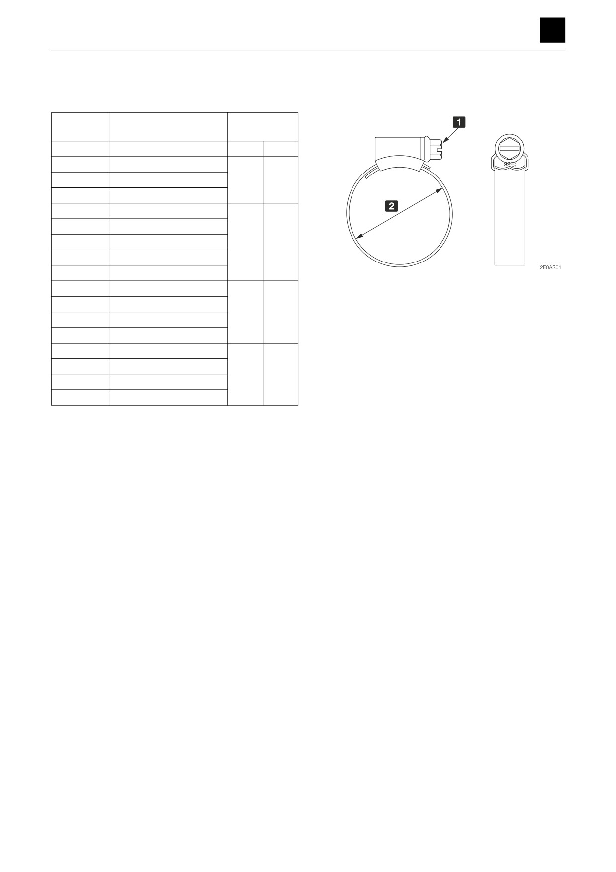
Hose clips
For the hydraulic hoses
Tightening
Part no.
Tightening range
torque
15337-*****
mm (in.)
N·m
ft.-lb
-00013
9.5 to 12 (0.37 to 0.47)
-00016
11 to 16 (0.43 to 0.63)
3.4
2.5
-00019
13 to 20 (0.51 to 0.79)
-00022
14 to 22 (0.55 to 0.87)
-00025
17 to 25 (0.67 to 0.98)
-00028
22 to 30 (0.87 to 1.18)
4.8
3.6
-00035
25 to 35 (0.98 to 1.38)
-00041
30 to 40 (1.18 to 1.57)
1
7 mm (0.28 in.)
-00048
35 to 50 (1.38 to 1.97)
2
Tightening range
-00054
40 to 55 (1.57 to 2.17)
5.8
4.3
-00060
45 to 60 (1.77 to 2.36)
-00070
55 to 70 (2.17 to 2.76)
-00080
60 to 80 (2.36 to 3.15)
-00090
70 to 90 (2.76 to 3.54)
6.7
5.0
-00102
80 to 100 (3.15 to 3.94)
-00115
90 to 120 (3.54 to 4.72)
4
TIGHTENING TORQUE
2E0AS00
SERVICE DATA
2
TIGHTENING TORQUE
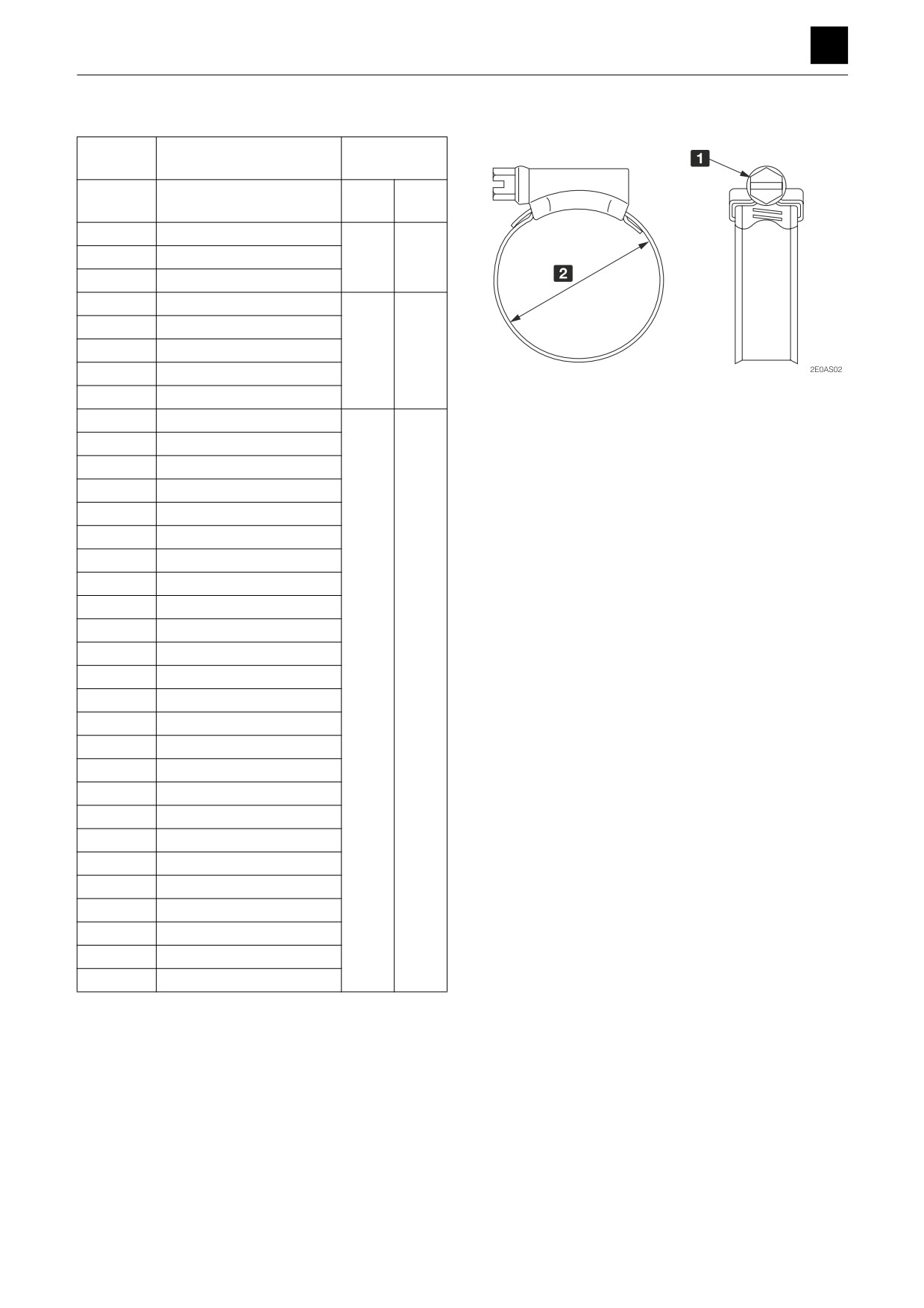
For hoses other than the hydraulic hoses
Tightening
Part no.
Tightening range
torque
15337-
mm (in.)
N·m
ft.-lb
*****
-00015
8 to 15 (0.31 to 0.59)
2.5 to
1.8 to
-00017
11 to 17 (0.43 to 0.67)
3.4
2.5
-00021
13 to 22 (0.51 to 0.87)
-00024
15 to 25 (0.59 to 0.98)
-00029
19 to 29 (0.75 to 1.14)
3.9 to
2.9 to
-00031
19 to 31 (0.75 to 1.22)
4.9
3.6
-00033
22 to 33 (0.87 to 1.30)
-00039
26 to 39 (1.02 to 1.54)
1
7 mm (0.28 in.)
2
Tightening range
-00045
32 to 45 (1.26 to 1.77)
-00051
32 to 51 (1.26 to 2.01)
-00052
38 to 51 (1.50 to 2.01)
-00057
44 to 57 (1.73 to 2.24)
-00061
40 to 61 (1.57 to 2.40)
-00066
50 to 66 (1.97 to 2.60)
-00069
50 to 69 (1.97 to 2.72)
-00071
50 to 71 (1.97 to 2.80)
-00076
58 to 76 (2.28 to 2.99)
-00081
60 to 81 (2.36 to 3.19)
-00086
68 to 86 (2.68 to 3.39)
-00091
70 to 91 (2.76 to 3.58)
4.9 to
3.6 to
-00096
77 to 96 (3.03 to 3.78)
5.9
4.3
-00101
80 to 101 (3.15 to 3.98)
-00113
87 to 113 (3.43 to 4.45)
-00121
100 to 121 (3.94 to 4.76)
-00131
110 to 131 (4.33 to 5.16)
-00139
104 to 138 (4.09 to 5.43)
-00166
130 to 166 (5.12 to 6.54)
-00181
150 to 181 (5.91 to 7.13)
-00206
175 to 206 (6.89 to 8.11)
-00232
200 to 232 (7.87 to 9.13)
-00257
226 to 257 (8.90 to 10.12)
-00283
251 to 283 (9.88 to 11.14)
-00308
277 to 307 (10.91 to 12.09)
5
TIGHTENING TORQUE
2E0AS00
3
FUNCTION
Hydraulic pump (Main)
Hydraulic pump (Sub)
Control valve
Pilot valve (control lever)
Pilot valve (swing)
Pilot valve (blade)
Pilot valve (travel)
Proportional control solenoid valve
Emergency shut-off valve
Solenoid valve
Shockless valve
Cylinders
Travel motor
Slew motor
Swivel joint
FUNCTION
3
HYDRAULIC PUMP (MAIN)
HYDRAULIC PUMP (MAIN)
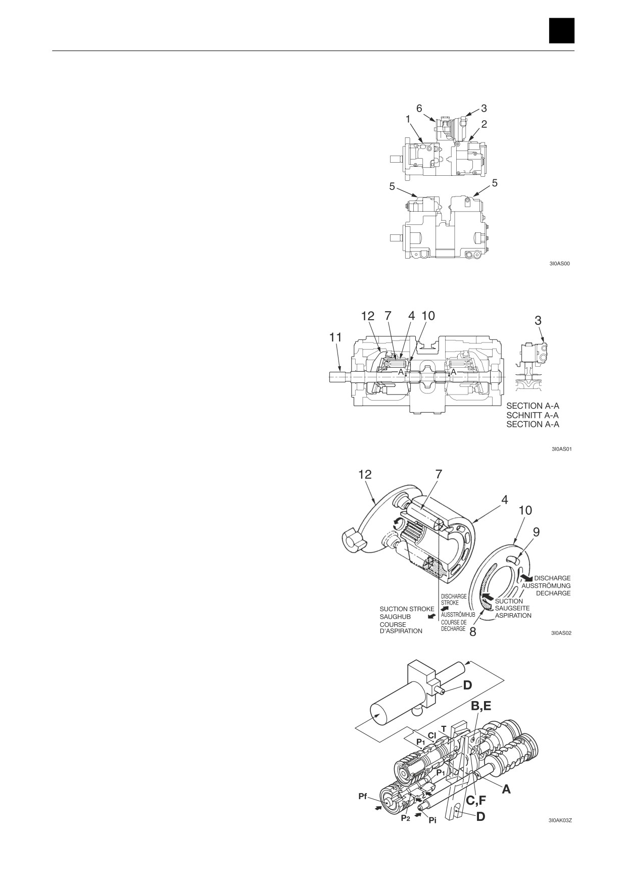
This pump is formed of two variable displacement piston
pumps (1) and (2) and a gear pump (3). The two variable
displacement piston pumps operate over the same shaft.
However, the gear pump (3) operates on a different shaft
than the variable displacement piston pumps.
Roughly speaking, this pump is formed of a cylinder
block (4) that produces rotating motion, a regulator (5)
that changes the discharge flow rate, and a PTO group
(6) that is used to transmit the gear pump motion to the
driving shaft.
Cylinder block
The cylinder block (4) is formed of pistons (7), and at its
end surface, it is in contact with the valve plate (10) that
contains the intake port (8) and the discharge port (9).
The cylinder block (4) rotates freely and is connected to
the shaft (11) via the spline. The swash plate (12), on the
other hand, is fixed at an angle to the housing, and the
pistons (7) are designed to rotate along with the swash
plate (12).
Here, the cylinder block (4) rotates as the shaft (11) is ro-
tated, and the pistons (7) mounted in the cylinder block
(4) follow and move back and forth with the motion of the
swash plate (12), which activates the suction and dis-
charge pumps.
In this way, the nine pistons (7) complete one stroke of in-
take and exhaust for every stroke of the cylinder block
(4). Thus, continuous operation of intake and exhaust
can be obtained by continuous rotation of the shaft (11).
The displacement of the pistons
(7) can be varied
through modification of the angle of inclination of the
swash plate (12) as the degree of displacement depends
on the inclination of the swash plate (12).
Regulator
This regulator is equipped with three control functions, a
flow rate control function for discharging only the neces-
sary amount according to the pilot pressure Pi from the
control valve, a function for controlling horsepower to
prevent excessive load on the motor using the discharge
pressures P1 and P2, and a power shift control function
for controlling the set pump horsepower setting using the
power shift pressure Pf from the Pr pump (2nd service
and blade). If these control functions are used together,
low-inclination operation commands (low flow rate com-
mands) are given priority based on mechanical calcula-
tions.
1
HYDRAULIC PUMP (MAIN)
3I0AS00
FUNCTION
3
HYDRAULIC PUMP (MAIN)
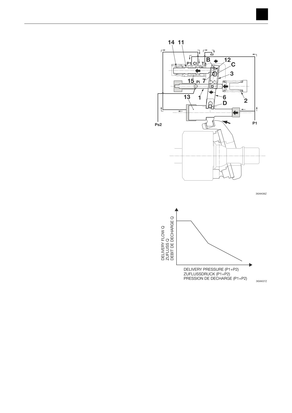
1. Flow rate control
The angle of inclination (discharge rate) of the swash
plate of the pump is controlled by the pilot pressure Pi
from the control valve.
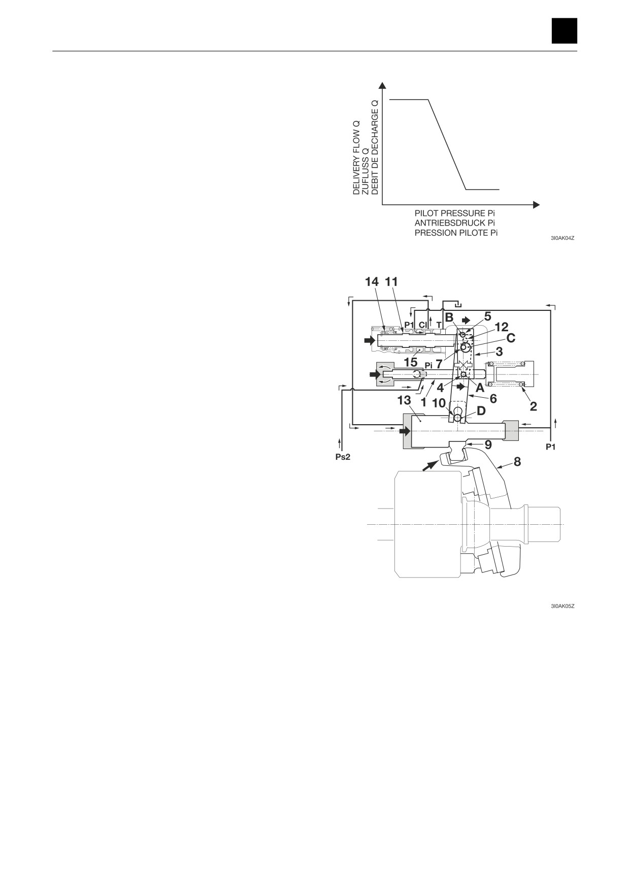
This regulator uses a load flow rate control (negative con-
trol) method through which the discharge rate Q is low-
ered as the pilot pressure Pi is increased, such that when
a command is issued for the pilot pressure Pi according
to the amount of flow required for operation, the pump
discharges only the necessary amount so that no power
is wasted unnecessarily.
Decrease in flow rate
When the pilot pressure Pi from port Ps2 in the control
valve is increased, the piston (1) moves to the right side
and stopped at a position at which the force of the spring
(2) is balanced with the hydraulic pressure.
The pin (4) attached to the lever (3) is inserted into the
groove (A) on the piston (1), and when the piston (1)
moves, the lever (3) turns clockwise around the securing
pin (5) of the pivot point (B).
The pin (7) attached to the lever (6) is inserted into the
hole (C) on the lever (3), and the pin (7) moves right when
the lever (3) rotates clockwise. The pin (10) secured to
the inclined pin (9) used to tilt the swash plate (8) is at-
tached to the second surface (D) of the lever (6), and the
lever (6) turns counter-clockwise around the second sur-
face (D) when the pin (7) moves. The spool (11) is linked
to the lever (6) via the pin (12) and moves to the right.
When the spool (11) moves, the discharge pressure P1
is transmitted to the port Cl through the spool (11) and
flows to the large-diameter section of the servo piston
(13). The discharge pressure P1 normally flows to the
small-diameter section of the servo piston (13), but the
servo piston (13) moves to the right due to the differential
area, causing the angle of inclination to decrease, which
results in the discharge pressure P1 flowing into the
large-diameter section.
When the servo piston (13) moves to the right, the sec-
ond surface (D) also moves to the right. The spring (14)
is attached to the spool (11) that normally exerts a pulling
force on the spool (11) that pulls it to the left, which caus-
es the pin (7) to be pushed into the hole (C) of the lever
(3). As can be inferred from the above, the lever (6) turns
counter-clockwise around the hole (C) when the second
surface (D) moves, resulting in the spool (11) moving to
the left. The movement of these parts causes the opening
between the sleeve (15) and the spool (11) to gradually
close, and the servo piston (13) stops at the position at
which the opening is completely closed.
2
HYDRAULIC PUMP (MAIN)
3I0AS00
FUNCTION
3
HYDRAULIC PUMP (MAIN)
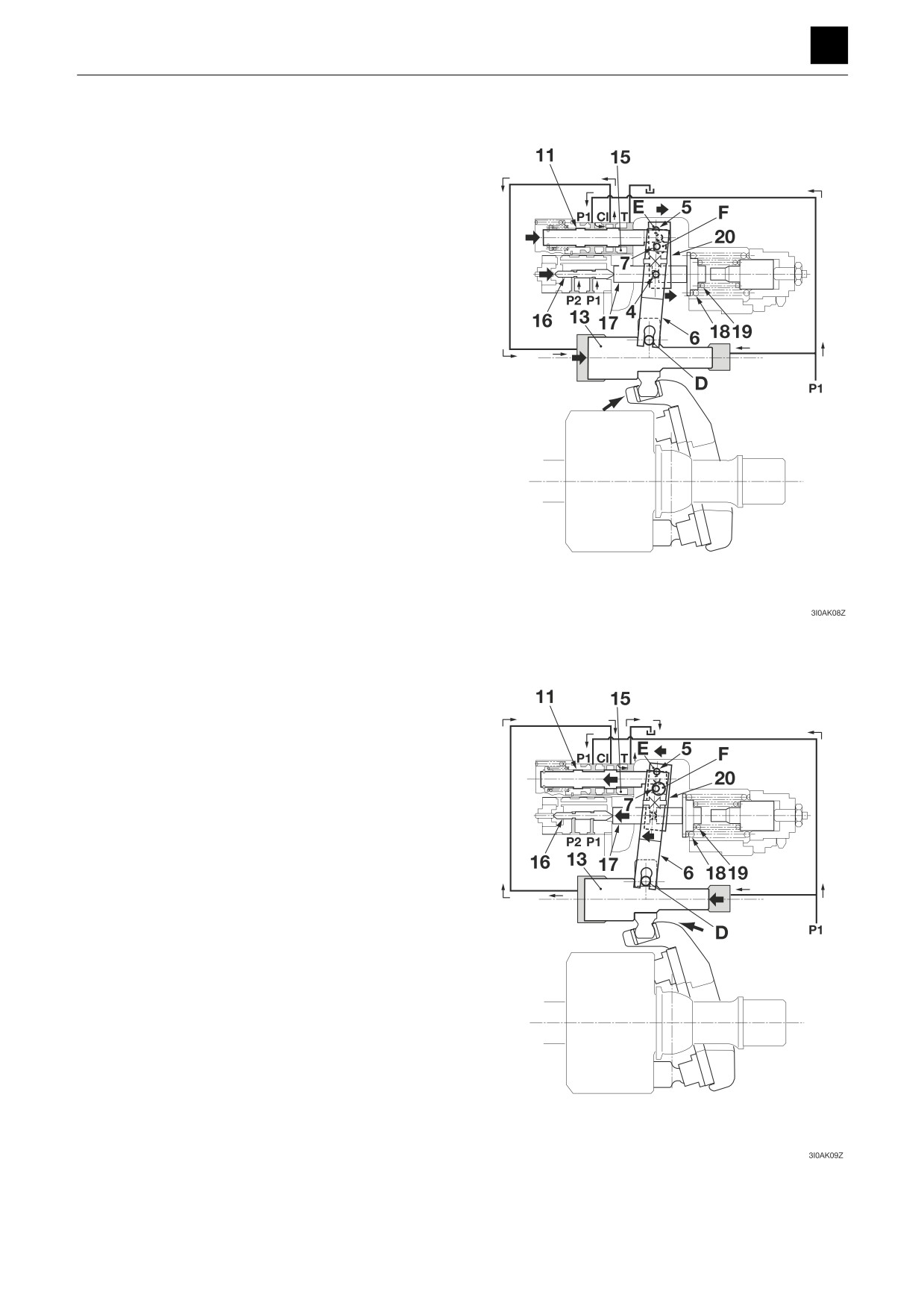
Increase in flow rate
When the pilot pressure Pi decreases, the piston (1)
moves to the left due to the force of the spring (2), and
the lever (3) turns clockwise around section B. The pin
(7) is pushed into the hole (C) on the lever (3) via the
spool (11), pin (12), and lever (6), which causes the lever
(6) to move counter-clockwise around the second width
(D) when the lever (3) moves clockwise, which results in
the spool (11) moving to the left.
When the spool (11) moves, port CI is connected to port
T, the pressure on the large-diameter section of the servo
piston (13) is released, and the servo piston (13) is
moved to the left by the discharge pressure P1 in the
small-diameter section, which causes the flow rate to in-
crease.
The second surface (D) moves to the left, causing the le-
ver (6) to turn clockwise around the hole (C), when the
servo piston (13) moves, resulting in the spool (11) mov-
ing to the right. The spool (11) continues to move until the
opening between the sleeve (15) and the spool (11) clos-
es and stops at the position at which the opening is
closed.
2. Horsepower control
As the discharge pressure P1 of the self-operating pump
and the discharge pressure P2 of the other pump in-
crease, the angle of inclination of the pump (discharge
rate) drops automatically such that the input torque is
controlled so as to be maintained below a set value. (The
input horsepower is constant when the rotation speed is
constant.)
With a tandem double pump, a simultaneous full-horse-
power method is used for operation according to the total
load pressure of the two pumps such that the regulators
in the two pumps are controlled and maintained at the
same angle of inclination (discharge rate) when horse-
power control is in effect. For this reason, when horse-
power control is in effect, engine overloading is prevent-
ed automatically independent of the load on the two
pumps.
3
HYDRAULIC PUMP (MAIN)
3I0AS00
FUNCTION
3
HYDRAULIC PUMP (MAIN)
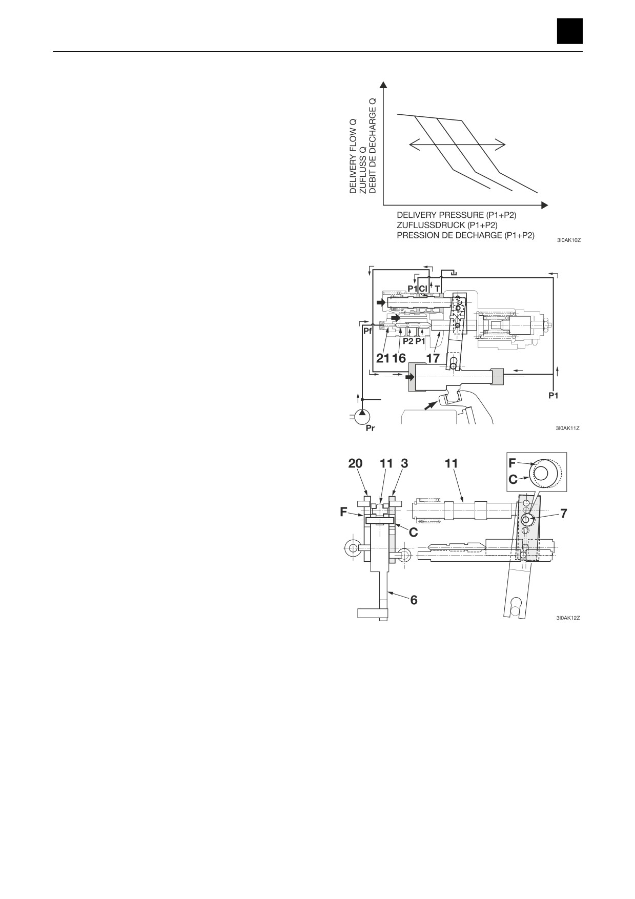
Prevention of excessive load
When the discharge pressure P1 of the self-operating
pump or the discharge pressure P2 of the other pump in-
creases, P1 and P2 are exerted on the step section of the
piston (16), which causes the rod (17) to be pushed to
the right to the position at which the spring force and oil
pressure of the spring (18) and spring (19) are balanced.
The movement of the rod (17) is transmitted to the lever
(20) via the pin (4), which causes the lever (20) to move
counter-clockwise around the pivot point (E). The pin (7)
attached to the lever (6) is thrust into the hole (F) on the
lever (20), which causes the lever (6) to move clockwise
around the second surface (D) when the lever (20)
moves counter-clockwise, resulting in the spool (11)
moving to the right.
When the spool (11) moves, the discharge pressure P1
causes the discharge rate in the large-diameter section
of the piston (13) to drop via port Cl, which works to pre-
vent excess load on the motor.
The movement of the servo piston (13) is transmitted to
the lever (6) via the second surface (D), which causes
the lever (6) to move counter-clockwise around the hole
(F), resulting in the spool (11) moving until the opening
between the spool (11) and the sleeve (15) and stopping
at the position at which the opening is closed.
Restoration of flow rate
When the discharge pressure P1 of the self-operating
pump or the discharge pressure P2 of the other pump
decreases, the rod (17) is pushed back by the spring
(18) and spring (19), and the lever (20) rotates clockwise
around the pivot point (E). The lever (6) turns counter-
clockwise around the second surface (D) when the lever
(20) turns clockwise, resulting in the spool (11) moving to
the left. As can be inferred from the above, port Cl opens
into the tank port, causing the pressure in the large-diam-
eter section of the servo piston (13) to be released, re-
sulting in the servo piston (13) moving to the left and the
pump discharge rate increasing.
The movement of the servo piston (13) is transmitted to
the spool (11) via the mechanism in the lever (6), and the
spool (11) continues to move until the opening between
the spool (11) and the sleeve (15) is closed.
4
HYDRAULIC PUMP (MAIN)
3I0AS00
FUNCTION
3
HYDRAULIC PUMP (MAIN)
3. Power shift (Lowered horsepower control)
The pressure from the Pr pump (2nd service and blade)
controls the set pump horsepower as a power shift pres-
sure Pf.
When the power shift pressure Pf is increased, the rod
(17) moves to the right via the pin (21) and piston (16),
which causes the angle of inclination of the pump to
drop and the set horsepower to decrease, as was de-
scribed in the explanation for operation to prevent ex-
cessive load for control of horsepower. Conversely, if
the power shift pressure Pf is decreased, the set
horsepower will increase.
4. Command override system for low-inclination (low flow
rate) operation
As described above, the inclination command for flow
rate and horsepower control is transmitted to the lever (6)
and spool (11) via the holes (C) and (F) in the lever (3)
and lever (20). In the diagram shown at right, the lever (3)
is being affected by a command that causes its angle of
inclination to be greater than that of the lever (20) such
that the pin (7) makes contact with only the hole (F) in the
lever (20), which has the smaller angle of inclination. As
a result, the hole (C) of the lever (3) remains open and
free of contact with the pin (7).
With this kind of mechanical selection system, low-incli-
nation commands for flow rate control and horsepower
control are given priority over other commands.
5
HYDRAULIC PUMP (MAIN)
3I0AS00
FUNCTION
3
HYDRAULIC PUMP (MAIN)
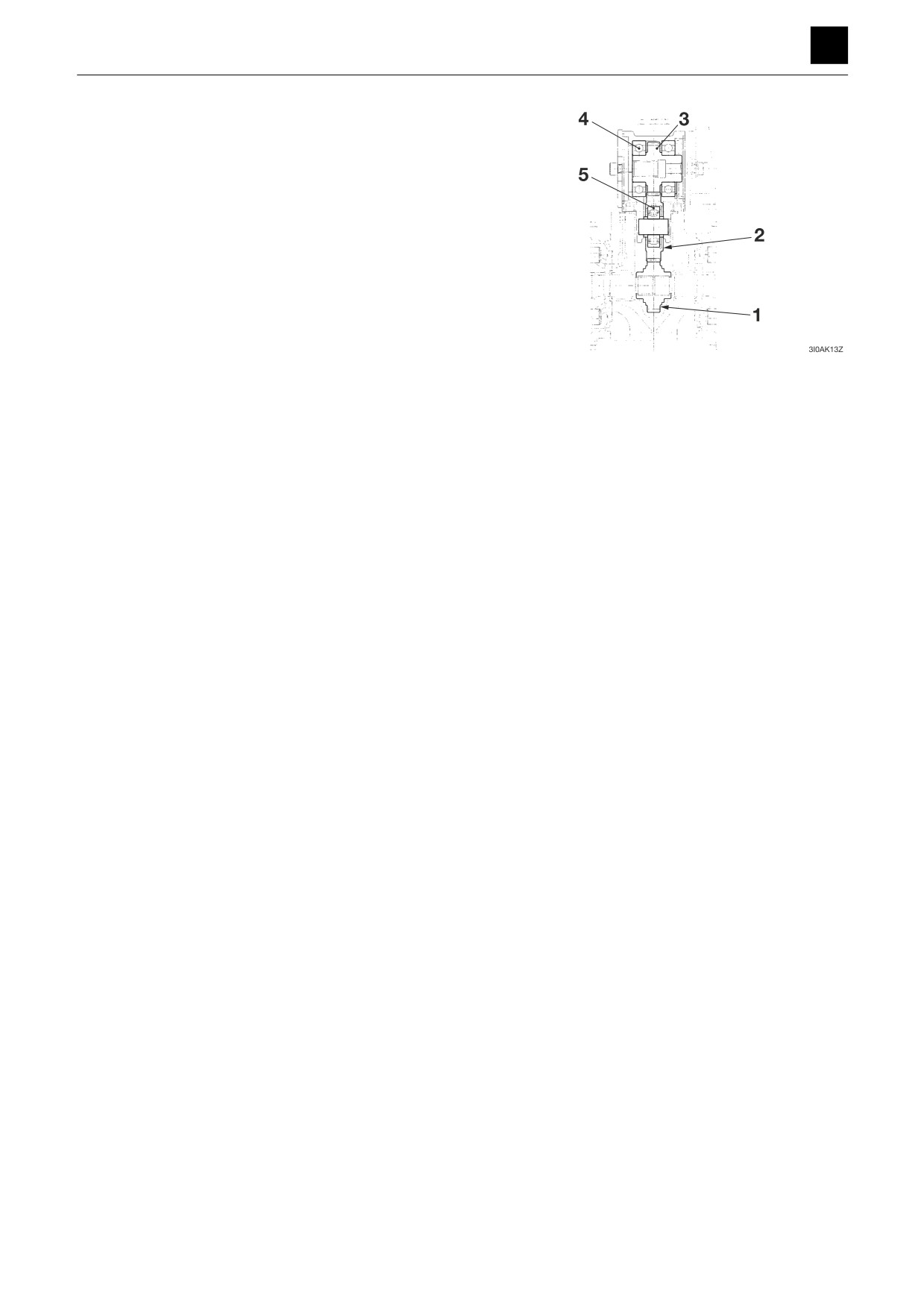
PTO group
The PTO group is formed of a 1st gear (1), 2nd gear (2),
and 3rd gear (3), and the 2nd gear (2) and 3rd gear (3)
are supported by a bearing (4) and a bearing (5), re-
spectively.
When the driving shaft rotates, the rotation of the driving
shaft is conveyed to the 1st gear (1) and transmitted to
the 3rd gear (3) via the 2nd gear (2) to drive the gear
pump connected to the 3rd gear (3).
6
HYDRAULIC PUMP (MAIN)
3I0AS00
FUNCTION
3
HYDRAULIC PUMP (SUB)
HYDRAULIC PUMP (SUB)
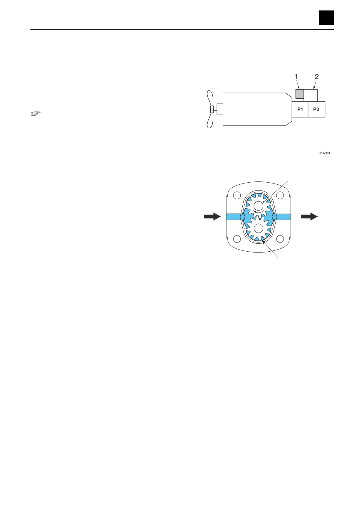
The hydraulic pump (sub) (1) is a gear pump that is a
constant-volume pump that discharges a constant vol-
ume of discharge material over a constant speed.
The hydraulic pump (sub) (1) is connected to the PTO
group (2) of the hydraulic pump (main) through gears
that transmit the rotation of the engine from the PTO
group.
Hydraulic pump, PTO group
The gear pump is composed of two mutually engaging
6
gears (drive gear (6) and driven gear (7)) that are con-
tained in a gear case. When the drive gear (6) is rotated,
the space between the case and the gears is filled with
the oil that flows from the inlet to the outlet.
7
3I1AQ02Z
1
HYDRAULIC PUMP (SUB)
3I1AS00
FUNCTION
3
CONTROL VALVE
CONTROL VALVE
1
CONTROL VALVE
3J0AS00
FUNCTION
3
CONTROL VALVE
2
CONTROL VALVE
3J0AS00
FUNCTION
3
CONTROL VALVE
When all spools are in the neutral position
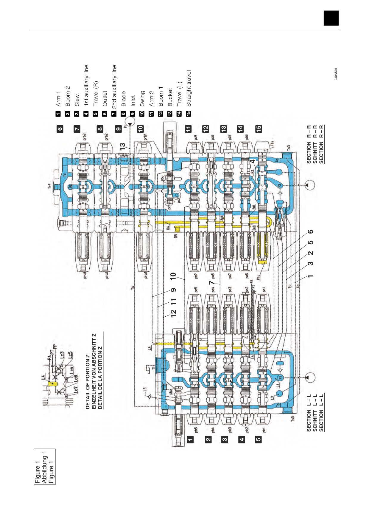
Neutral passage (Fig. 1), (Fig. 2)
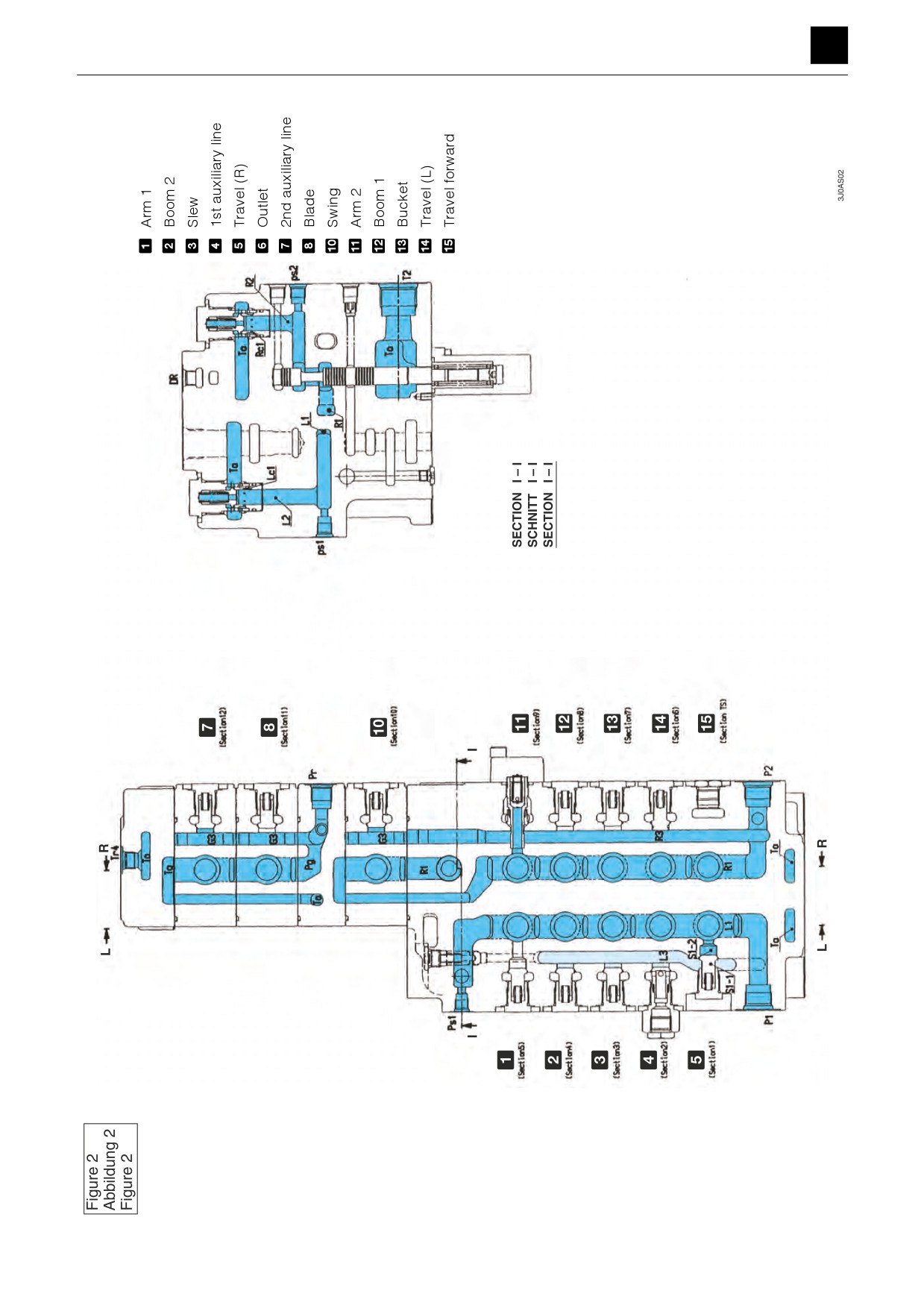
Fig. 2
The oil supplied from the port P1 is sent from the neutral passage (L1) to the neutral passage (L2) and through the
opening (Lc1) in the low-pressure relief valve into the tank passage (Ta) to be returned to ports T1 and T2.
The oil supplied from the port P2 is sent from the neutral passage (R1) to the oil passage (R2) via the neutral cut spool
and through the opening (Rc1) in the low-pressure relief into the tank passage (Ta) to be returned to ports T1 and T2.
The pressure in the pressure chambers (L2) and (R2) of the upstream flow section of the low-pressure relief vale flows
into the pumps from ports ps1 and ps2 to control the discharge rates of pumps P1 and P2.
If an excessive amount of oil flows into the neutral passages, the low-pressure relief valve operates to prevent the pres-
sure in ports ps1 and ps2 from rising to an abnormal level.
Fig. 1
In addition, the oil supplied from the port P1 flows from the passage (2) into the parallel passage (L3) via the bridge (4)
and straight travel valve and through the passage (1). The auxiliary, slew, boom 2, and arm 1 sections are connected
together via each check valve, and the flow is stopped by the spool in each section.
Fig. 2
The parallel passage (L3) is connected to the neutral passage (L1) via the passage (S1-2) and the check valve (S1-1)
such that the oil flows from port P1 to the parallel passage (L3) without going through the straight travel valve when the
travel section (Section 1) is not operating.
Fig. 1
The oil (3rd pump) supplied from port Pr flows from the passage (13) in the inlet section into the neutral passage (Pg).
The oil that flows into the blade section flows from the passage (Tg) into the inlet section via the outlet section (cover)
and flows into the oil in the machine body tank passage (Ta).
Fig.2
In addition, the flow of the oil supplied from the port Pr is connected to the blade section via the parallel passage (G3)
and check valve and is stopped by the spool.
Signal passage (Fig. 1)
The oil supplied from the port PP flows to port PT via the opening (Lc3). At the same time, it also flows from the land
(Rc3) through the land (Lc4) and passage (6) and into the drain passage (DR).
Part of the oil supplied from the port PP flows to port PA from the opening (Lc5). In addition, it also flows from the bucket
spool land (Rc4) and into the drain passage (DR) via the passages (L4), (9), and (R4).
The oil that passes through the opening (Lc6) flows into the tank passage (Ta) from the land (Lc7). The oil also flows
from the travel spool land (Rc5) and into the tank passage (Ta) through the passage (5).
At this time, the oil that flows through the passage (5) flows into the switching pressure chamber (Pts) from the spool
cycle passage of the straight travel valve.
The chamber (Tts) on the opposite side from the straight travel valve spool is connected to the tank passage (Ta) via
a notch opening in the outer circumference of the spool and used to decrease the impact of shocks during switching.
3
CONTROL VALVE
3J0AS00
FUNCTION
3
CONTROL VALVE
Independent operation
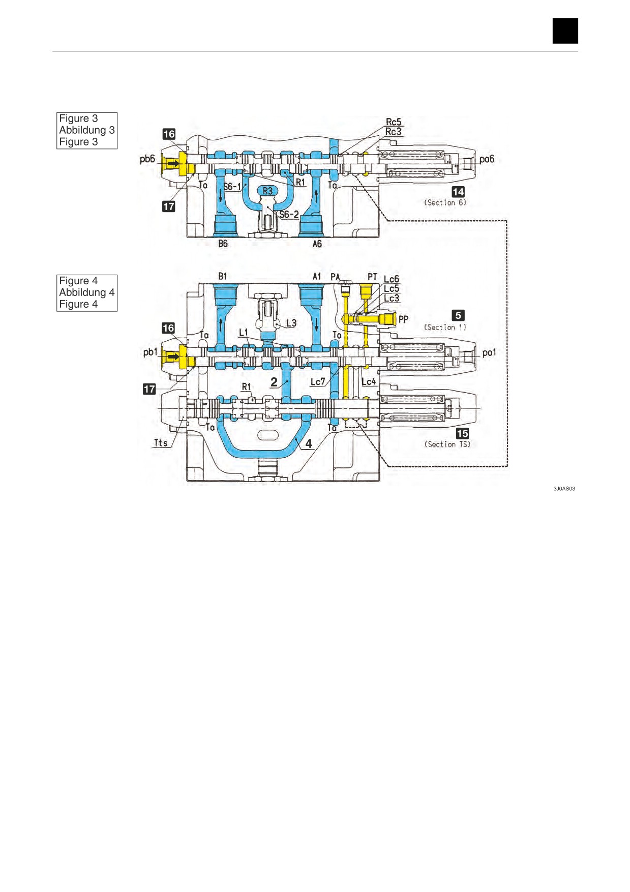
Travel spool switching (Fig. 3), (Fig. 4)
5 Travel (R)
f Neutral
d Travel (L)
g Switching
e Straight travel
When the pressure from the pilot port pb1 (pa1) of the travel (R) section (section 1) increases causing the travel spool
to be switched, the oil supplied from the port P1 flows from the neutral passage (L1) through the spool neck and into
the port B1 (A1). The oil that returns back returns to the tank passage (Ta) from port A1 (B1) through the spool neck.
When the pressure from the pilot port pb6 (pa6) of the travel (L) section (section 6) increases causing the travel spool
to be switched, the oil supplied from the port P2 flows from the neutral passage (R1) through the spool neck or the
passage (S6-1) and into the port B6 (A6).
At this time, the poppet (S6-2) does not open as the pressure in the parallel passage (R3) is the same as that in the
passage (S6-1).
The oil that returns back returns to the tank passage (Ta) from port A6 (B6) through the spool neck.
Either the land (Lc4) or the land (Rc3) closes when the spool in either travel section (Section 1 or Section 6) switches.
The flow of the oil supplied from the port PP into the tank passage is blocked, which causes the pressure in the port
PT to increase.
4
CONTROL VALVE
3J0AS00
FUNCTION
3
CONTROL VALVE
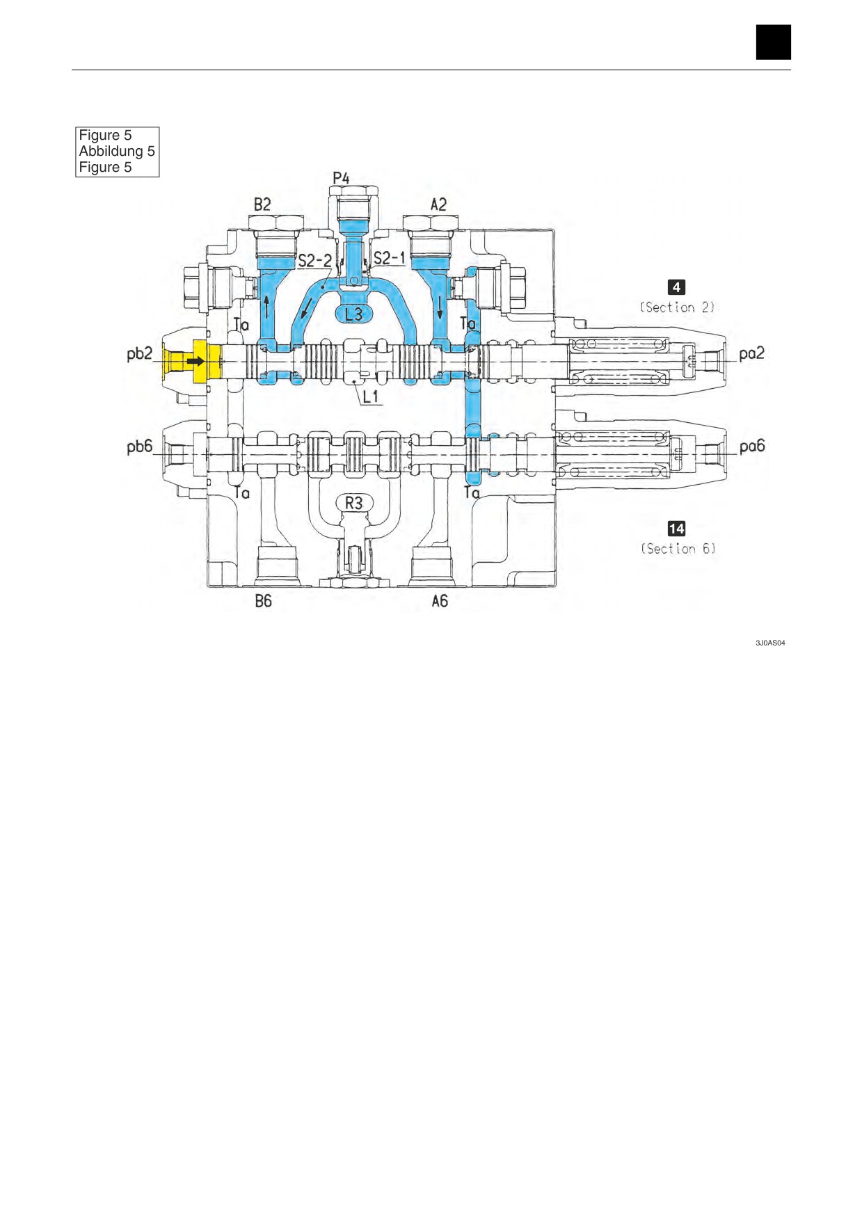
1st auxiliary line spool switching (Fig. 5)
4 1st auxiliary line
d Travel (L)
The neutral passage (L1) closes when the pressure from the pilot port pb2 (pa2) of the 1st auxiliary line (Section 2) is
increased causing the spool to switch. The oil supplied from the port P1 flows from the parallel passage (L3) and into
port B2 (A2) through the load check valve (S2-1), passage (S2-2), and spool neck.
The oil that returns back returns to the tank passage (Ta) from port A2 (B2) through the spool neck.
A load check is used in this section that allows external oil to flow from port P4.
5
CONTROL VALVE
3J0AS00
FUNCTION
3
CONTROL VALVE
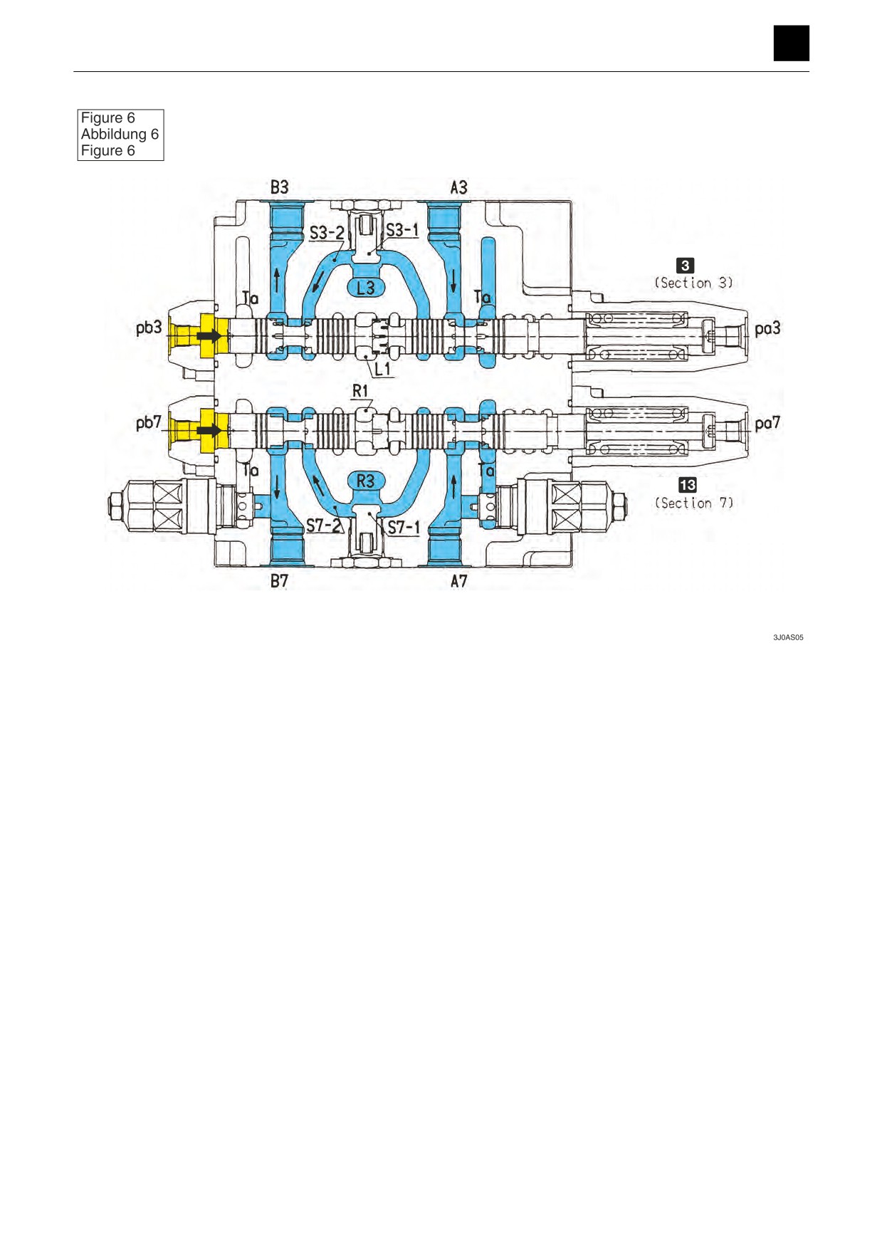
3 Slew
c Bucket
Slew spool switching (Fig. 6)
The neutral passage (L1) closes when the pressure in the pilot port Pb3 (Pa3) in the slew section (Section 3) increases
and causes the slew spool to switch. The oil supplied from the port P1 flows from the parallel passage (L3) through the
load check valve (S3-1), passage (S3-2), and spool neck and into the passage B3 (A3).
The oil that returns back returns from port A3 (B3) through the spool neck to the tank passage (Ta).
Bucket spool switching (Fig. 6)
The neutral passage (R1) closes when the pressure in the pilot port pb7 (pa7) in the bucket section (Section 7) increas-
es and causes the bucket spool to switch. The oil supplied from port P2 flows from the parallel passage (R3) and into
port B7 (A7) through the load check valve (S7-1), passage (S7-2), and spool neck.
The oil that returns back returns from port A7 (B7) through the spool neck to the tank passage (Ta).
6
CONTROL VALVE
3J0AS00
FUNCTION
3
CONTROL VALVE
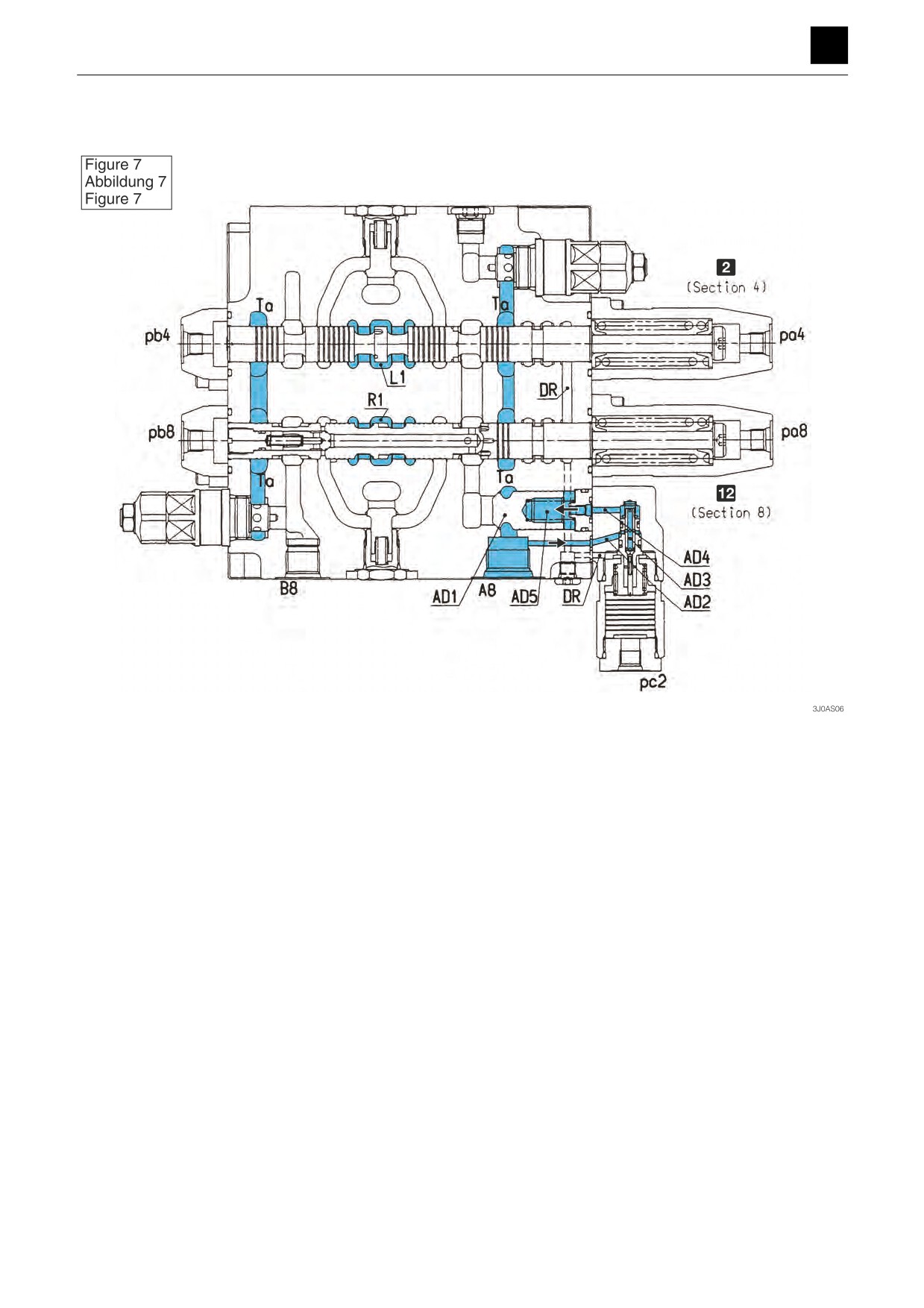
Boom spool switching
Neutral position (Fig. 7)
2 Boom 2
b Boom 1
This valve is installed in the anti-drift valve on the cylinder bottom side of the boom 1.
When in the neutral position, the poppet (AD1) is firmly seated by the pressure of the port (A8) flowing from the spring
chamber (AD5) through the passage (AD2), poppet (AD3), and passage (AD4).
7
CONTROL VALVE
3J0AS00
FUNCTION
3
CONTROL VALVE
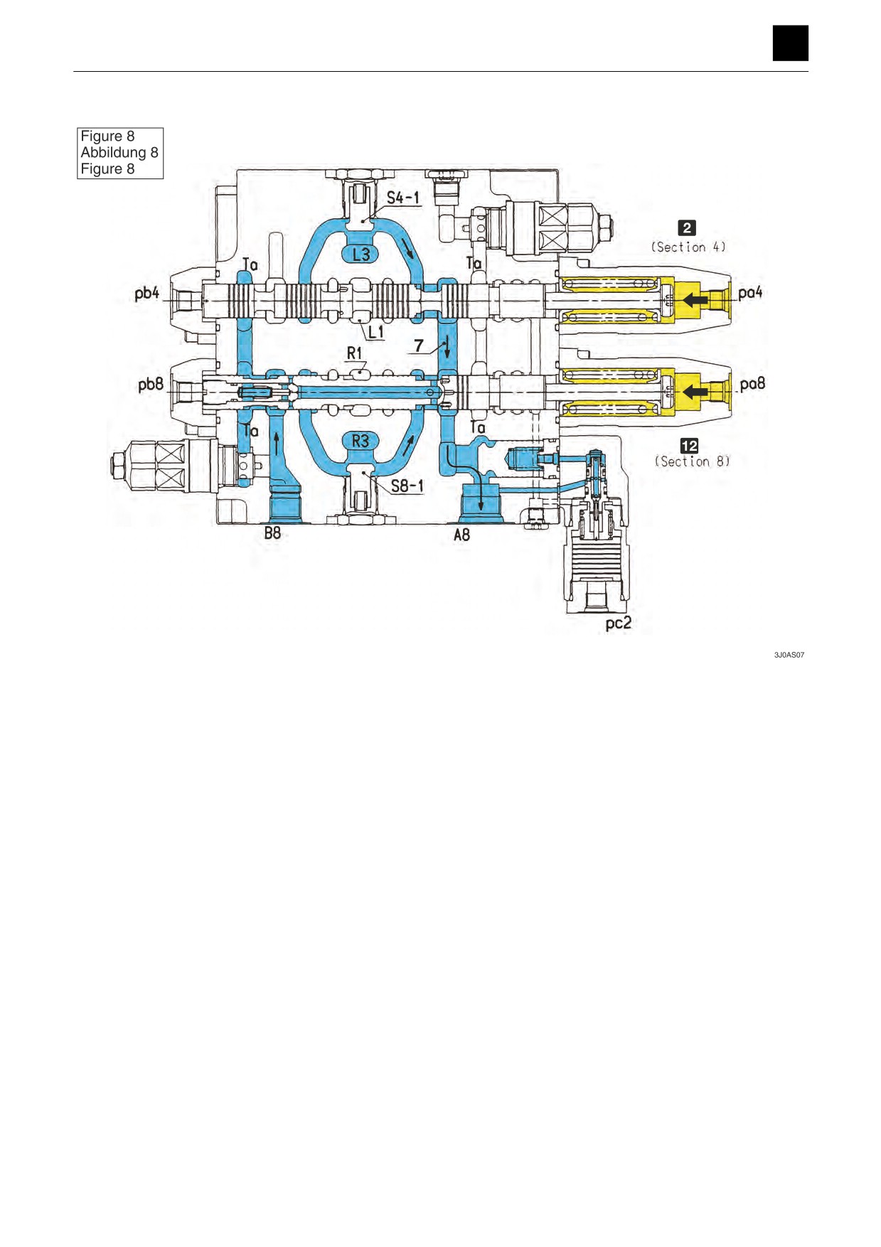
Raising (2nd-speed flow) (Fig. 8)
2 Boom 2
b Boom 1
The neutral passage (R1) closes when the pressure in the pilot port pa8 in the boom 1 section (Section 8) increases
and causes the boom 1 spool to switch. The oil supplied from the port P2 flows through the parallel passage (R3), load
check valve (S8-1), and spool neck to the port A8.
The neutral passage (L1) closes when the pressure in the pilot port pa4 in the boom 2 section (Section 4) increases
and causes the boom 2 spool to switch. The oil supplied from the port P1 flows through the parallel passage (L3), load
check valve (S4-1), spool neck, and passage (7) to the port A8. The oil that returns back returns from port B8 through
the spool neck to the tank passage (Ta).
8
CONTROL VALVE
3J0AS00
FUNCTION
3
CONTROL VALVE
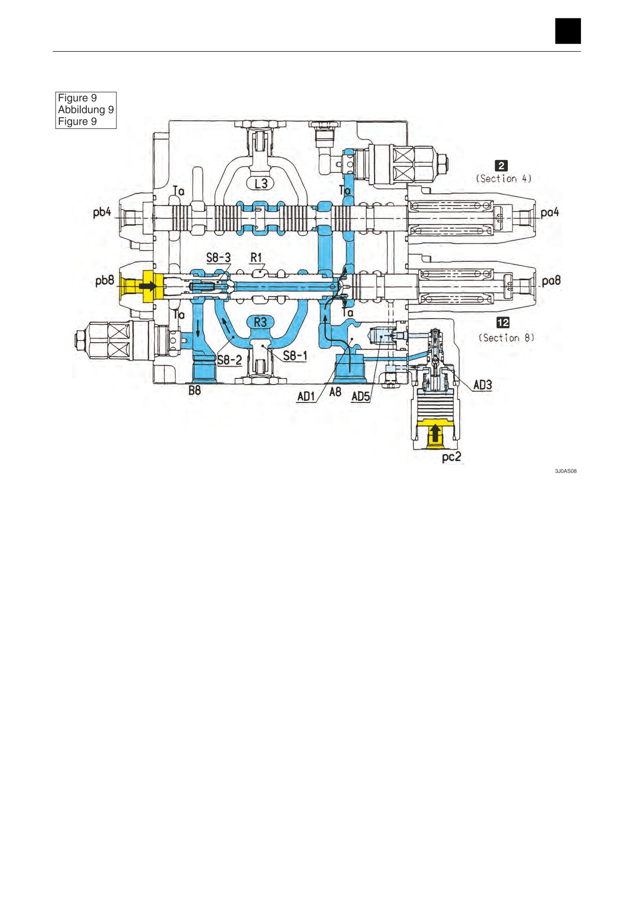
Lowering (Reclaiming) (Fig. 9)
2 Boom 2
b Boom 1
The neutral passage (R1) closes when the pressure in the pilot port pb8 in the boom 1 section (Section 8) increases
and causes the boom 1 spool to switch. The oil supplied from the port P2 flows through the parallel passage (R3), load
check valve (S8-1), and spool neck to the port B8. Simultaneously, when the pressure in the port pc2 increases causing
the poppet (AD3) of the anti-drift valve to switch and the pressure in the spring chamber (AD5) to drop, the poppet
(AD1) opens, and oil returning from the port A8 flows into the tank passage (Ta). Part of the oil returning back pushes
on and opens the poppet (S8-3) inside the boom 1 spool, and flows through the passage (S8-2) into the port B8 to
prevent cavitation from forming on the cylinder load side.
9
CONTROL VALVE
3J0AS00
FUNCTION
3
CONTROL VALVE
Arm spool switching
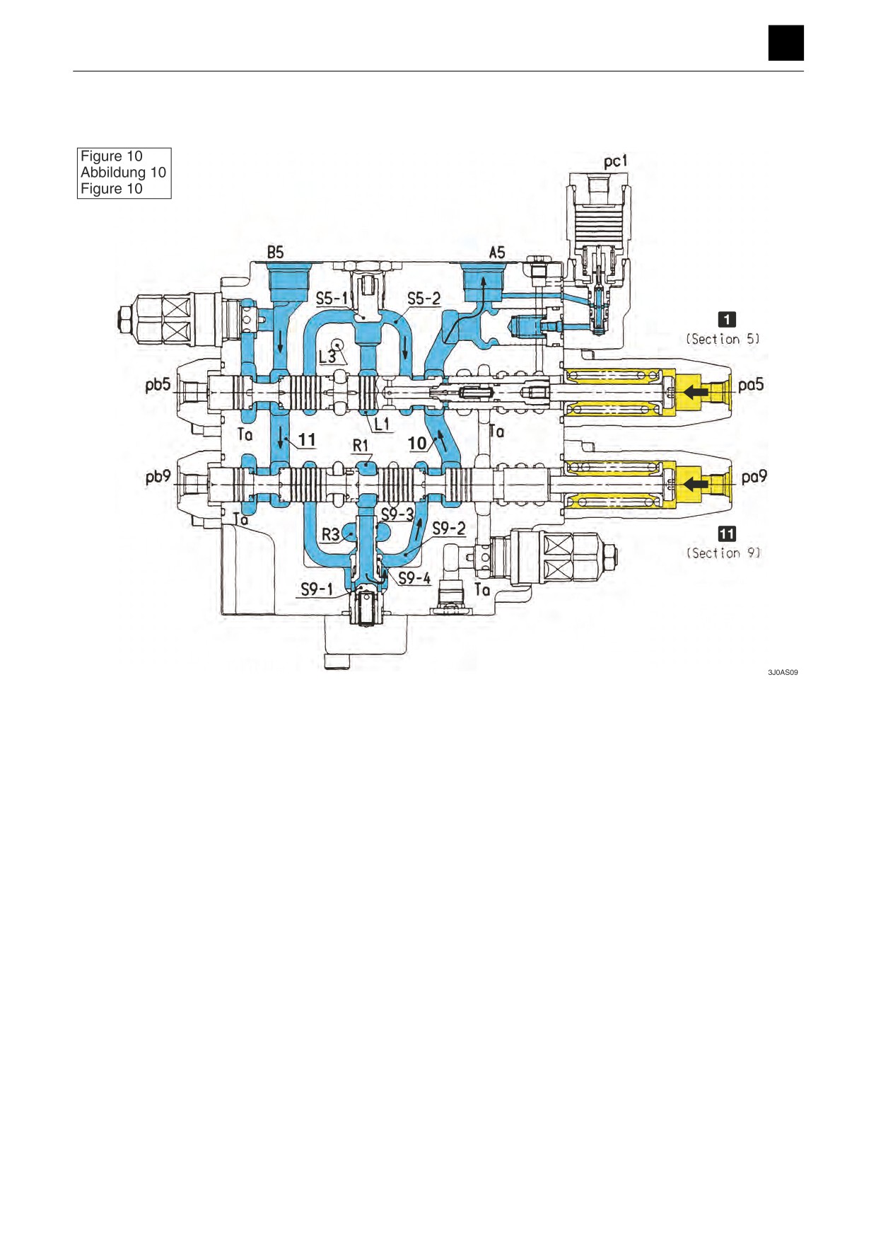
Dumping (2nd-speed flow) (Fig. 10)
1 Arm 1
a Arm 2
When the pressure in the pilot port pb5 of the arm 1 section (Section 5) increases causing the arm 1 spool to switch,
the oil supplied from the port P1 flows from the neutral passage (L1) through the load check valve (S5-1), passage (S5-
2), and spool neck and into the port A5.
When the pressure in the pilot port pa9 of the arm 2 section (Section 9) increases causing the arm 2 spool to switch,
the oil supplied from the port P2 flows from the neutral passage (R1) through the load check valve (S9-1), passage (S9-
2), spool neck, and passage (10) and into the port A5. Simultaneously, part of the oil supplied from the port P2 flows
from the opening (S9-3) in the passage (R3) through the check valve (S9-4), passage (S9-2), and passage (10) and
into the port A5. The oil that returns back returns from the port B5 through the arm 1 spool neck back into the tank
passage (Ta), and the oil from the passage (11) returns through the arm 2 spool neck back into the tank passage (Ta).
10
CONTROL VALVE
3J0AS00
FUNCTION
3
CONTROL VALVE
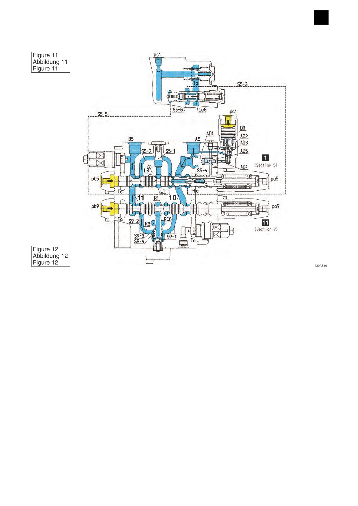
Crowding (2nd-speed flow) (Fig. 11), (Fig. 12)
1 Arm 1
a Arm 2
When the pressure in the pilot port pb5 of the arm 1 section (Section 5) increases causing the arm 1 spool to switch,
the oil supplied from the port P1 flows from the neutral passage (L1) through the load check valve (S5-1), passage (S5-
2), and spool neck and into the port B5.
When the pressure in the pilot port pb9 of the arm 2 section (Section 9) increases causing the arm 2 spool to switch,
the oil supplied from the port P2 flows from the neutral passage (R1) through the load check valve (S9-1), passage (S9-
2), spool neck, and passage (11) and into the port B5. Simultaneously, part of the oil supplied from the port P2 flows
from the opening (S9-3) in the passage (R3) through the check valve (S9-4), passage (S9-2), and passage (11) and
into the port B5.
When the pressure in the port pc1 increases causing the poppet (AD3) of the anti-drift valve to switch and the pressure
in the spring chamber (AD5) to drop, the poppet (AD1) opens, and oil returning from the port A5 flows through the
spool neck, passage (S5-3), and arm variable reclaiming opening (Lc8) back into the tank passage (Ta). Part of the oil
returning back pushes on and opens the poppet (S5-4) inside the arm 1 spool, and flows through the passage (S5-2)
into the port B5 to increase the speed of the cylinder. This also works to prevent cavitation from forming on the bottom
side.
Variable reclaiming (during crowding) (Fig. 11), (Fig. 12)
During crowding of the arm, the spool (S5-6) moves in response to the pressure in the passage (S5-2) flowing from the
passage (S5-5), causing the degree to which the arm variable reclaiming opening (Lc8) is opened to change. If the
pressure in the passage (S5-2) is high, the amount that the spool (S5-6) moves increases causing the degree to which
the opening (Lc8) is opened to drop. This causes the reclaiming flow rate to change in response to the pressure at the
bottom of the am cylinder.
11
CONTROL VALVE
3J0AS00
FUNCTION
3
CONTROL VALVE
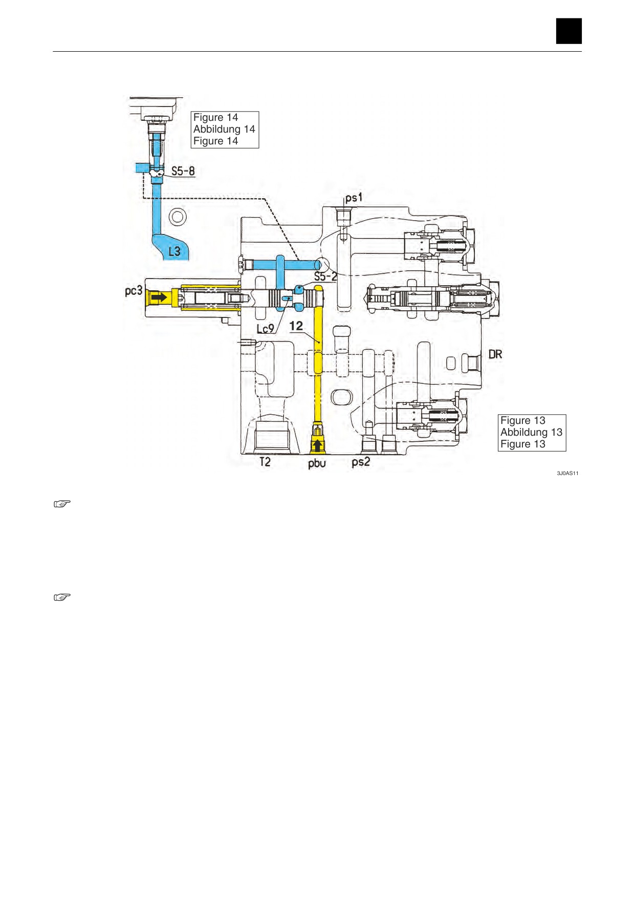
Parallel opening for the arm (Fig. 10), (Fig. 11), (Fig. 12,) (Fig. 13), (Fig. 14)
Fig. 10, Fig. 11
There are openings formed in both the arm 1 section (Section 5) and arm 2 section (Section 9) in the parallel circuit for
the arm for this valve that are used to control the flow rate so that the arm speed is at a proper speed even during
composite operation.
After the parallel circuit of the arm 2 section (Section 2) closes the opening (RC6) of the sleeve (S9-3) from the parallel
passage (R3), it is connected to the passage (S9-2) through the poppet (S9-4).
Fig. 13, Fig. 14
After the parallel circuit of the arm 1 section (Section 5) pushes open the poppet (S5-8) from the parallel passage (L3)
and the opening (Lc9) of the parallel variable opening spool closes, the passages (S5-2) and (12) are connected to-
gether.
The degree to which the opening (Lc9) is opened can be changed using increases in pressure in the pilot port (pbu)
(pc3).
12
CONTROL VALVE
3J0AS00
FUNCTION
3
CONTROL VALVE
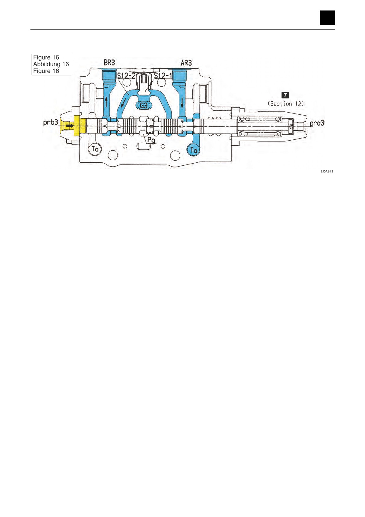
Add-on spool switching (Fig. 16)
The 2nd auxiliary line will be presented here as a typical example of this kind of switching.
The neutral passage (Pg) closes when the pressure from the pilot port prb3 (pra3) of the 2nd auxiliary line (Section 12)
is increased causing the spool to switch. The oil supplied from the port Pr flows from the parallel passage (G3) through
the load check valve (S12-1), passage (S12-2), and spool neck and into port BR3 (AR3).
The oil that returns back returns from port AR3 (BR3) through the spool neck to the tank passage (Ta).
13
CONTROL VALVE
3J0AS00
FUNCTION
3
CONTROL VALVE
Relief valve
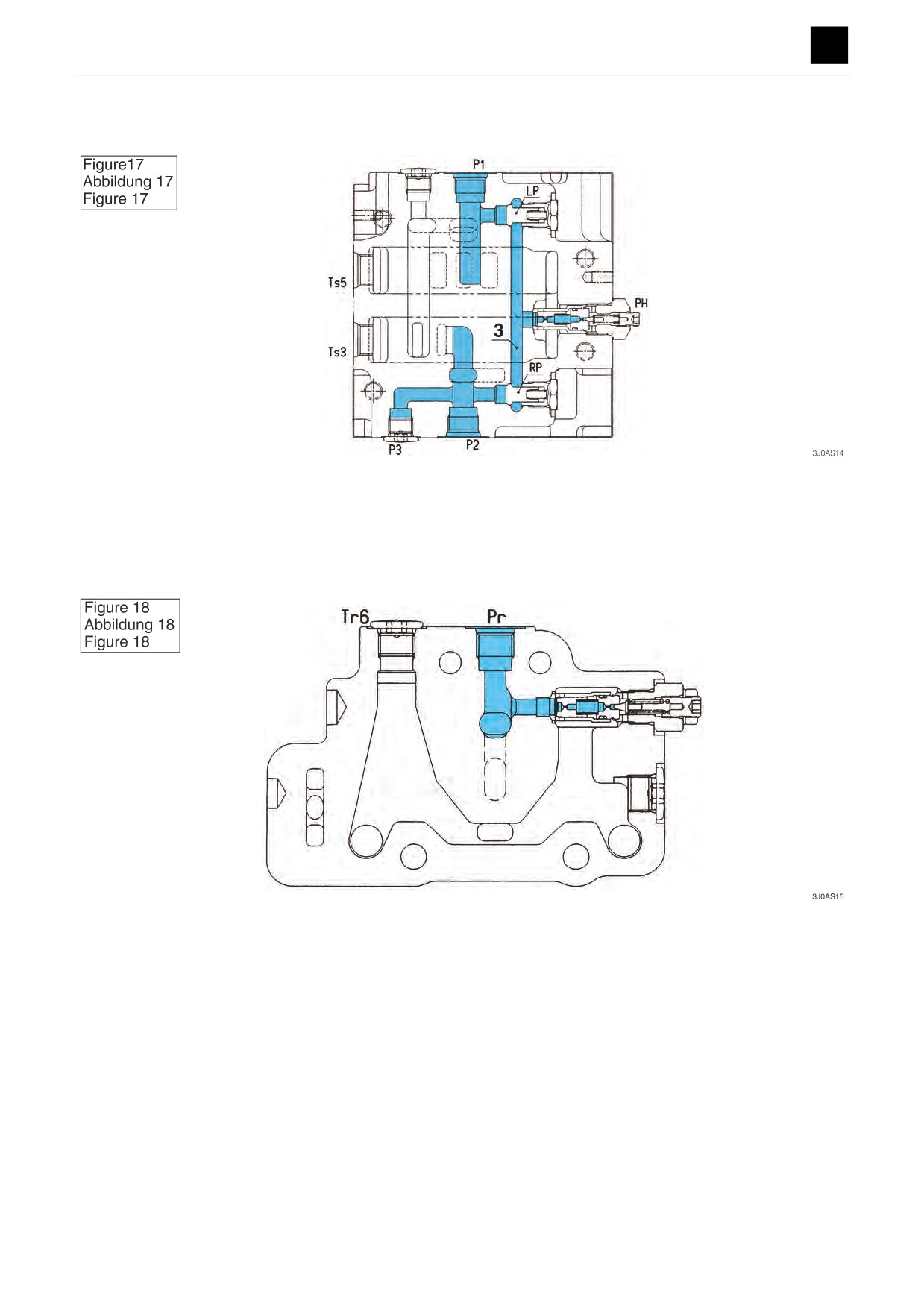
Main relief valve for the machine body (Fig. 17)
The oil supplied from the port P1 flows through the poppet (LP), or the oil supplied from the port P2 flows through the
poppet (RP) and passage (3), and into the main relief valve. When the main relief valve operates, the maximum pres-
sure of the pumps on the P1 and P2 sides is restricted to a set value.
Relief valve for the add-on Pr (Fig. 18)
The oil supplied from the port Pr flows into the main relief valve. The maximum pressure of the Pr pump is limited to a
set value through operation of the main relief valve.
Overload relief valve
An overload relief valve is provided in each of the cylinder ports in each section that prevents the pressure in the ac-
tuator from rising to an abnormal level due to an external force.
This relief valve is also equipped with a function designed to prevent suction of oil from the tank and cavitation from
occurring when the pressure in the cylinder port becomes a negative pressure.
14
CONTROL VALVE
3J0AS00
FUNCTION
3
CONTROL VALVE
Composite operation
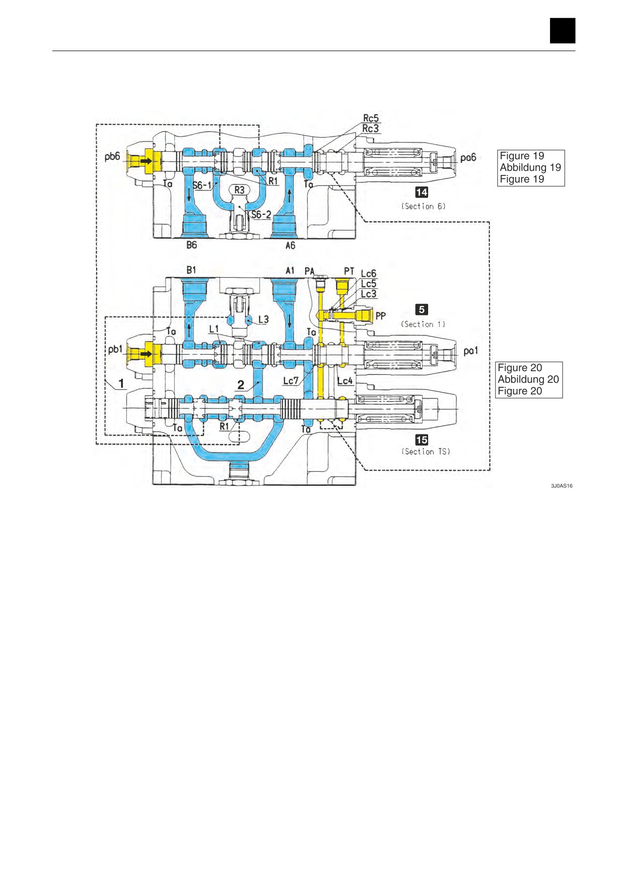
Composite travel operation (Fig. 19), (Fig. 20)
During simultaneous left-and-right travel operation (during forward travel, reverse travel, or spin turns), when opera-
tions other than travel operations are run simultaneously, or when simultaneous left-and-right travel operations are run
while other operations other than travel operations are being run, the oil supplied from the port PP is blocked from flow-
ing to the tank passage (Ta) by signal land sections other than travel sections switched with the lands (Lc4), (Lc7),
(Rc3), and (Rc5), which causes the pressure in the signal passage to increase to the relief pressure setting for the hy-
draulic generator for signals.
The straight travel spool is switched by the increase in the signal pressure. The pressure in the ports PT and PA also
increases.
When the straight travel spool switches, the oil supplied from the port P1 flows from the neutral passage (L1) and into
the travel (R) section (Section 1), and at the same time, through the passage (2), straight travel spool neck, and neutral
passage (R1) and into the travel (L) section (Section 6).
The oil supplied from the port P2 flows through the straight travel spool neck and passage (1) and into the parallel pas-
sage (L3).
The travel sections (Section 1 and Section 6) are moved by the oil supplied from the port P1 and devices in other op-
erating sections are moved by the oil supplied from the port P2, which works to prevent veering in travel during com-
posite operations involving simultaneous left-and-right travel operation and operation of other devices.
If the load pressure in other sections is higher than the load pressure in the travel section (Section 6), part of the oil
supplied from the port P2 pushes on and opens the poppet (S6-2) and flows through the opening at the end of the
poppet and into the passage (S6-1). This works to alleviate the impact from shocks from deceleration with travel during
switching of the straight travel valve.
15
CONTROL VALVE
3J0AS00
FUNCTION
3
CONTROL VALVE
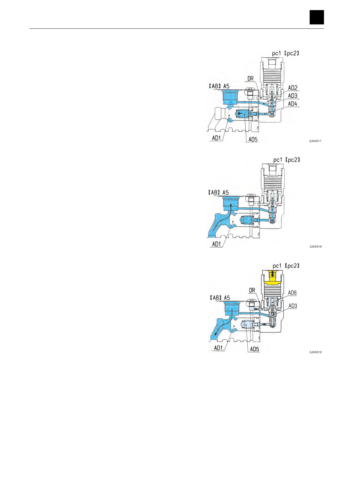
Anti-drift valve
The anti-drift valve is used to prevent spontaneous drop
of the arm (boom) cylinder and is mounted in the cylinder
port on the arm rod (boom bottom) side.
In neutral, the cylinder port pressure flows into the spring
chamber (AD5) from the passage (AD2) through the hol-
low hole in the poppet (AD3) and the passage (AD4).
The poppet (AD1) is firmly seated by the pressure differ-
ential produced by the spring force and differential area
of the poppet.
When the arm is in the dump position (the boom is
raised), the oil supplied from the pump pushes the pop-
pet (AD1) open and flows into the cylinder port.
When the arm is in the crowd position (the arm is low-
ered), the pc1 (pc2) pressure increases causing the
poppet (AD3) to switch, which leads to the oil in the
spring chamber (AD5) to flow through the hollow hole in
the poppet (AD3) and hollow hole in the spool (AD6) and
into the drain passage (DR). This causes the poppet
(AD1) to open, and the oil that returned from the cylinder
port flows into the tank passage (Ta) through the spool.
16
CONTROL VALVE
3J0AS00
FUNCTION
3
CONTROL VALVE
Main relief valve
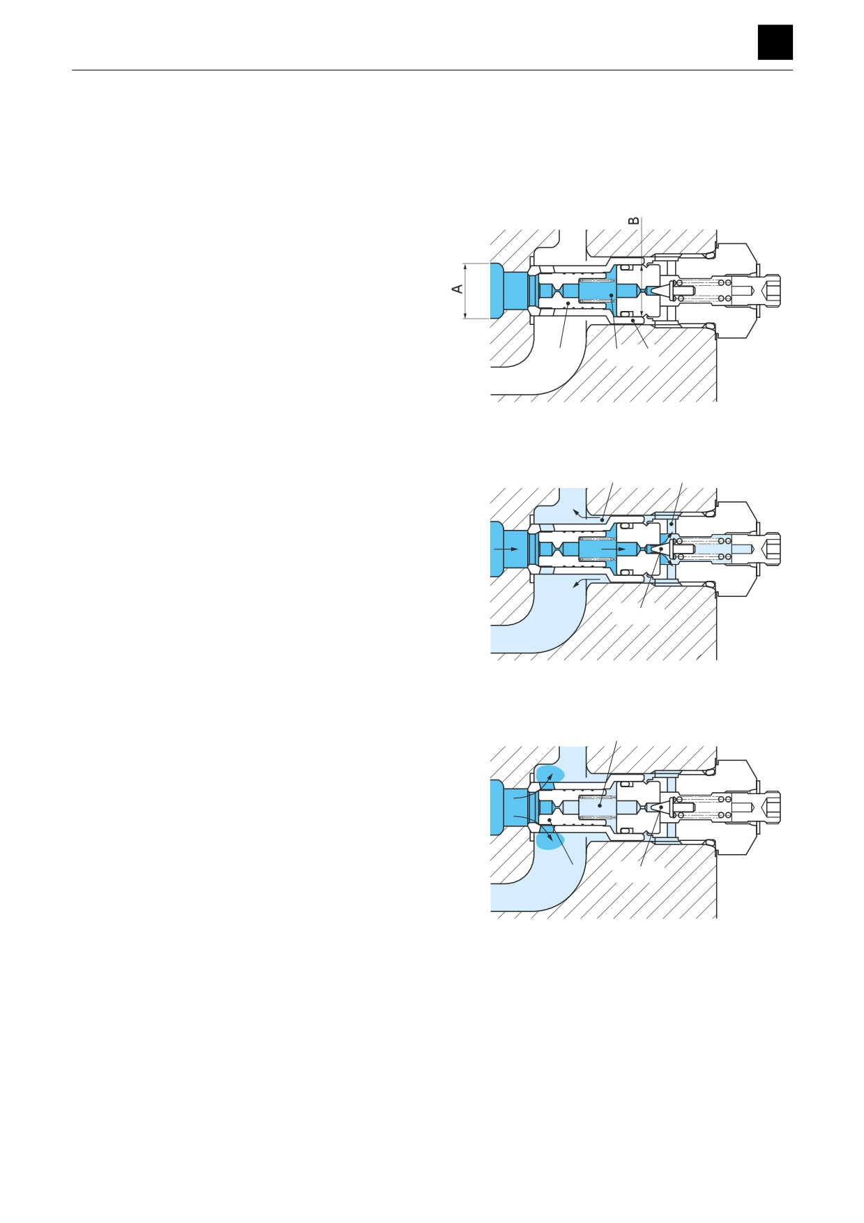
The main relief valve is mounted between the pump cir-
cuit and tank circuit of each inlet housing and serves to
maintain the circuit pressure at the set value.
Machine body main relief valve
This relief valve is installed between the neutral passage
"LP"
“HP” and low-pressure passage “LP,” and oil flows
through the opening hole in the main poppet into the in-
ternal cavity (C) to fill the internal cavity (C).
In addition, the opening in the sleeve (2) and the main
"HP"
poppet (1) are firmly seated using the different areas of
“A” and “B.”
1
C
2
3J0AS20
When the pressure in the neutral passage “HP” reaches
the set pilot spring force, the pilot poppet (3) opens.
E
D
"LP"
The oil flows around the pilot poppet (3) from the hole (D)
and through the gap (E) into the tank passage “LP.”
"HP"
3
3J0AS21
When the pilot poppet (3) is opened, the pressure in the
internal cavity (C) drops causing the main poppet (1) to
C
"LP"
open, which results in the oil in “HP” flowing into the con-
necting passage “LP.”
"HP"
1
3
3J0AS22
17
CONTROL VALVE
3J0AS00
FUNCTION
3
CONTROL VALVE
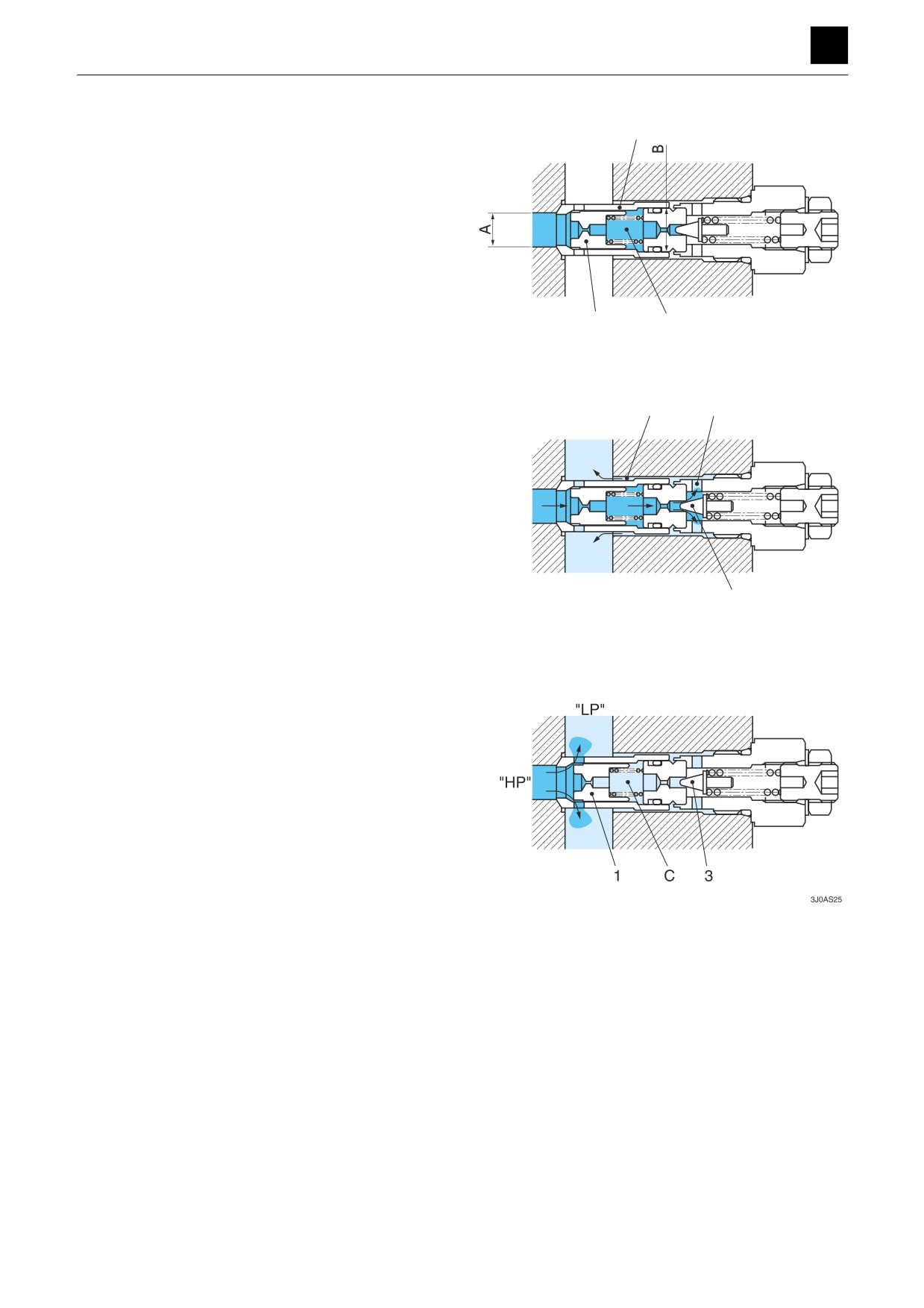
Add-on main relief valve
2
This relief valve is installed between the neutral passage
“HP” and low-pressure passage “HP,” and oil flows
"LP"
through the opening hole in the main poppet into the in-
ternal cavity (C) to fill the internal cavity (C).
In addition, the opening in the sleeve (2) and the main
poppet (1) are firmly seated using the different areas of
"HP"
“A” and “B.”
1
C
3J0AS23
When the pressure in the neutral passage “HP” reaches
the set pilot spring force, the pilot poppet (3) opens.
E
D
The oil flows around the pilot poppet (3) from the hole (D)
"LP"
and through the gap (E) into the tank passage “LP.”
"HP"
3
3J0AS24
When the pilot poppet (3) is opened, the pressure in the
internal cavity (C) drops causing the main poppet (1) to
open, which results in the oil in “HP” flowing into the con-
necting passage “LP.”
18
CONTROL VALVE
3J0AS00
FUNCTION
3
CONTROL VALVE
Port relief valve
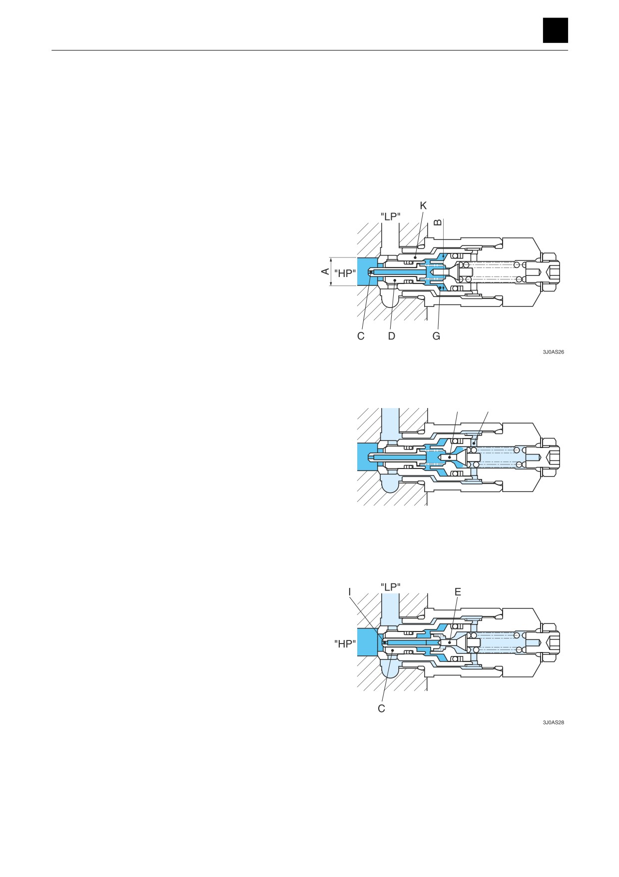
The port relief valve is located between the actuator and
the tank circuit. It protects the actuator from pressure
shock caused by the sudden blocking of the actuator
port or by overloading, or absorbs abnormal pressure
caused by an external force. In addition, it also prevents
the oil from forming suction cavitation in the tank when
the actuator port experiences a negative pressure.
This relief valve is installed between the cylinder port
“HP” and low-pressure passage “LP,” and oil flows
through the opening hole in the piston (C) to fill the inter-
nal cavity (G).
In addition, the sleeve (K) and the main poppet (D) are
firmly seated using the different areas of “A” and “B.”
When the pressure in the cylinder port “HP” reaches the
set spring force of the pilot poppet, the pilot poppet (E)
opens.
"LP"
E H
The oil flows around the circumference of the poppet and
through the hole (H) into the low-pressure passage “LP.”
"HP"
3J0AS27
When the pilot poppet (E) is opened, oil flows through the
opening (I) in the piston (C), which produces a pressure
differential with the passage “HP” on the back of the pis-
ton (C), causing the piston (C) to move and set the pop-
pet (E).
19
CONTROL VALVE
3J0AS00
FUNCTION
3
CONTROL VALVE
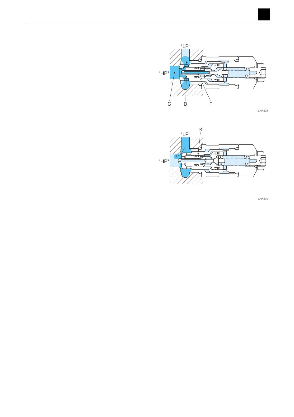
The oil flowing from the passage “HP” to the back of the
poppet (D) flows only through the gap between the pop-
pet (D) and piston (C) and the opening (F), which causes
the pressure differential to increase. This causes the
poppet (D) to open, resulting in oil flowing into the direct
passage “LP.”
An anti-boiled unit that supplies oil when cavitation forms
is mounted in the cylinder port “HP” in this relief valve.
The sleeve (K) opens due to the differential area between
“A” and “B” when the pressure of the cylinder port “HP”
from the low-pressure side “LP” is low.
The oil from the low-pressure side “LP” flows into the low-
pressure side of the cylinder port “HP,” which prevents
cavitation from forming.
20
CONTROL VALVE
3J0AS00
FUNCTION
3
CONTROL VALVE
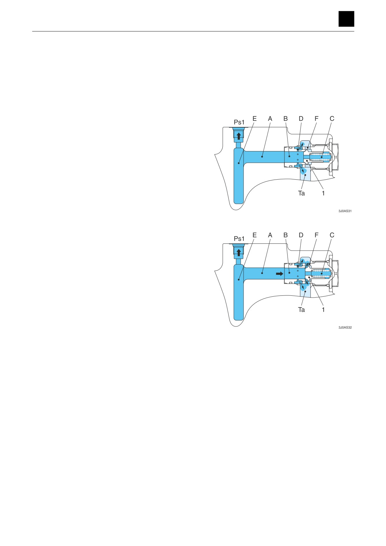
Negative control valve
This valve supplies negative control signals to the vari-
able displacement hydraulic pumps.
The negative control signals maintain the angle of incli-
nation of the swashplate so that the discharge rate of the
pump is kept at the minimum rate when the engine is
stopped.
Generation of signal pressure
The oil supplied from the pump port (P1) flows through
the neutral passage (L1) and from the neutral down-
stream passage (A) through the negative control open-
ing (D) into the tank passage.
At this time, a pressure is generated in the passage (B)
by the negative control opening (D) that flows into the
negative control signal port (Ps1) from the passage (E).
When the main spool for upstream flow through the neu-
tral downstream passage (A) is operated, the oil flowing
through the neutral downstream passage (A) decreases
in volume, causing the negative control signal pressure
to become low.
Relief operation
If an excessive amount of oil flows into the neutral down-
stream passage (A), the pressure generated in the pas-
sage (B) by the negative control opening (D) travels into
the chamber (C) in back of the poppet, which causes the
poppet to move due to the difference in the size of the
area on which pressure is exerted between the passage
(B) and the chamber (C). When the poppet moves, the oil
flows from the passage (B) through the hole passage (F)
in the plug and into the tank passage (Ta). This works to
prevent excessive amounts of pressure from being pro-
duced in the negative control signal pressure port.
21
CONTROL VALVE
3J0AS00