Takeuchi Hydraulic excavator TB1140 (Serial No. 514400002~). Operator's Manual - page 1
FOREWORD
This manual, which is written for engineers who service the machine, describes procedures for disassembly and as-
sembly, inspection and maintenance, and troubleshooting, as well as maintenance reference values and an outline of
the specifications. Refer to this manual during daily work to improve your services. Note that the information is subject
to change without notice due to design modifications made to the machine from time to time by the manufacturer.
Directional terms: front, rear, left, right
In this manual, the “front” refers to the end of the machine where the dozer blade is mounted, while the “rear” refers to
the other end where the travel motor is mounted. The “right” or “left” refers to the side viewed by a person sitting in the
operator’s seat.
Machine serial number
The machine serial number is stamped on the identification plate. Be sure to include this number when sending a report
or inquiry or when ordering parts.
Control of manual
Appoint a person in charge of keeping the manuals up to date in your company and inform us of the person’s name
for our records. Any revisions or additions to this manual will be sent to the person.
Symbols used in this manual
The symbols used in this manual have the following meanings.
Indicates the machine serial number.
Means “Refer to the section quoted.”
Indicates the mass of the equipment or machine.
Means “Tighten to the torque specified here.”
Indicates the use of thread-locking compound.
Indicates the use of grease.
Manual structure
This manual consists of the following parts.
1.
Safety
2.
Service data
3.
Function
4.
Disassembly and assembly
5.
Troubleshooting
6.
Other
1
SAFETY
Safety alert symbol
1-2
Safety precautions
1-3
Cautions when working
1-9
1-1
SAFETY
SAFETY ALERT SYMBOL
1
SAFETY ALERT SYMBOL
This symbol represents the safety
alert.
The message that follows the symbol
contains important information re-
garding human safety.
Read and understand the message to
avoid personal injury or death.
Safety label
Safety labels are used to alert operators or other people
exposed to the risks of injury or damage. There are the
following three types of labels.
Read the labels carefully as they are important for your
safety.
DANGER
The word “DANGER” indicates an imminently hazardous
situation which, if not avoided, is likely to result in serious
injury or death.
WARNING
The word “WARNING” indicates a potentially hazardous
situation which, if not avoided, could result in serious inju-
ry or death.
CAUTION
The word “CAUTION” indicates a potentially hazardous
situation which, if not avoided, may result in minor or
moderate injury.
IMPORTANT: The word “IMPORTANT” is used to alert
operators and maintenance personnel about situations
which could result in damage to the machine and its com-
ponents.
This manual is intended for trained and qualified person-
nel only. Warnings or cautions described in this manual
do not necessarily cover all safety measures. It is also im-
possible to cover all hazards and risks which may be as-
sociated with the maintenance of the machine in every
environment. For maintenance work, each person must
take adequate safety precautions against possible haz-
ards in the respective working environment.
1-2
SAFETY
SAFETY PRECAUTIONS
1
Install an extinguisher and a first aid kit
SAFETY PRECAUTIONS
Observe all safety rules
• Operation, inspection and maintenance of this ma-
chine must be performed only by a trained and quali-
fied person.
• All rules, regulations, precautions and safety proce-
dures must be understood and followed when per-
forming operation, inspection and maintenance of this
machine.
• Do not perform any operation, inspection or mainte-
nance of this machine when under the influence of al-
cohol, drugs, medication, fatigue or insufficient sleep.
1BAA02Z
• Install an extinguisher to fight a fire, and learn how to
Wear safe clothing and protective gear
use it.
• Prepare a first aid kit and keep it at a designated
place.
• Decide on the procedures to be used in case of fire or
other hazards.
• Decide on and take note of the contact(s) in case of
emergency.
Place a “Do not operate” alert sign
Serious injury or death may result if an unauthorized per-
son starts the engine or touches the controls during in-
spection or maintenance.
1BAA01Z
• Before performing maintenance, stop the engine, re-
•
Do not wear loose clothing or any accessory that can
move the key and store it in a safe place.
catch on the controls or the moving parts of the ma-
• Prominently display a “Do not operate” alert sign on
chine.
places such as the starter switch and the control lever.
•
Do not wear clothing stained with oil or grease that can
Place another sign outside of the machine as neces-
easily catch fire.
sary.
•
Wear protective gear such as helmet, safety shoes,
protective goggles, respirator, gloves and earmuffs,
Use the correct tools
as appropriate, depending on the work involved. Es-
pecially make sure to wear protective eye-wear and
mask when working with a grinding/polishing/sanding
machine, hammer or compressed air, as metal frag-
ments or other objects could scatter in such an envi-
ronment.
•
Wear hearing protectors when operating the machine.
Loud and prolonged noise can damage or destroy
your hearing.
1BAA03Z
Do not use damaged or weakened tools or tools de-
signed for other purposes. Use only the correct tools for
the work involved.
1-3
SAFETY
SAFETY PRECAUTIONS
1
Regularly replace the safety-critical parts
When the canopy is tilted up
• Regularly replace fuel hoses to prevent a fire hazard.
• If the canopy is raised or lowered while the engine is
Hoses wear out over time, even if they do not show any
moving, the machine may accidentally start moving,
symptom of wear.
resulting in severe injury to the maintenance person-
• Regardless of the replacement schedule, replace im-
nel. Make sure that the working equipment has been
mediately if a symptom of wear is found.
lowered to the ground and the engine has been turned
off before raising/lowering the canopy.
• When the canopy is tilted up, firmly secure the canopy
Explosionproof lighting
with a stopper to prevent it from falling.
Keep the machine clean
1BAA04Z
To prevent an ignition or explosion, use explosion-proof
lights when inspecting fuel, oil, coolant or battery fluid.
1BAA06Z
• Clean the machine before performing maintenance
Prohibit access by unauthorized persons
and try to keep it clean.
• Before washing, cover the electrical parts with vinyl to
prevent water from entering, as this could cause a
short-circuit or malfunction. Do not use water or steam
to wash the battery, sensors, connectors or the opera-
tor’s seat area.
Stop the engine before performing maintenance
Make sure the engine is stopped before starting inspec-
tion or maintenance. If maintenance must be performed
with the engine running, always work as a 2-person team,
communicating with each other.
• One of them must sit at the operator’s seat and stop
1BAA05Z
the engine whenever necessary. He/she must take
Do not allow unauthorized personnel in the work area
care not to touch the lever or pedal unless necessary.
while working.
• The one who performs maintenance must make sure to
Take particular care that no unauthorized person is
keep his/her body or clothing away from the moving
present when grinding, welding or using a hammer.
part of the machine.
Prepare the work area
• Select a level and firm ground on which to perform
maintenance work. Make sure that the work area is
light enough and well ventilated.
• Straighten any obstacle or dangerous object, remove
any spill of oil or grease and clean the work area.
1-4
SAFETY
SAFETY PRECAUTIONS
1
Keep clear of the moving fan and belt
When working on the machine
1BAA07Z
1BAA09Z
• Any object that can be easily caught in moving parts
• To prevent slipping/falling from machine, clear the
must be kept away.
footing and observe the following:
• If a hand or tool becomes trapped in the fan or fan belt,
a. Do not spill oil or grease on the machine.
you could lose your finger. Do not touch the fan or belt
b. Keep the machine tidy and clean.
while they are moving.
c. Be careful when walking around the machine.
• Never jump down from the machine. Climb up/down
the ladder (steps) holding the handrail to support your
When working under the machine
weight in a three point secure stance (hand and feet).
• Wear protective gear according to the work involved.
Securing the working equipment
When replacing/repairing the bucket teeth or side cutter,
secure the relevant equipment to prevent any accidental
movement.
Secure the engine hood and guard when they are
open
Firmly secure the machine when the engine hood or
guard is left open. Do not keep the hood or guard open
1BAA08Z
on a windy day or if the machine is parked on a slope.
• Before performing maintenance or repairs under the
machine, set all movable equipment against the
ground or in the lowermost position.
Place heavy components in a stable position
• Place chocks under the crawler tracks to secure the
machine.
• If it is unavoidably necessary to work under the raised
machine or working equipment, be sure to firmly sup-
port it by using an arm stopper, wooden block, stand
or safety brace. Never go under the raised machine or
working equipment without such protection measures.
1BAA10Z
When it is necessary to temporally place a heavy compo-
nent, such as the hoe attachment, on the ground during
removal or installation, be sure to place it in a stable po-
sition.
1-5
SAFETY
SAFETY PRECAUTIONS
1
Caution when filling with fuel or oil
Be careful with hot and pressurized components
1BAA11Z
1BAA12Z
• Keep away from heat, sparks and flame while filling
Before performing inspection and maintenance, stop the
with fuel or oil.
engine and allow the machine to cool down.
• Never remove the fuel cap or try to fuel when the en-
• The engine, muffler, radiator, hydraulic lines, sliding
gine is running or still hot.
parts and many other parts of the machine are hot im-
• Maintain control of the fuel filler nozzle when filling the
mediately after the engine is stopped. Wait until it
tank.
cools before making any inspection or adjustments.
• Refill with fuel or oil outdoors or in a well ventilated
• The engine coolant, hydraulic oil and other oils are
place, with the engine turned off.
also hot and under high pressure. Touching these liq-
• Clean up spilled fuel or oil immediately.
uids will cause burns.
• Do not overfill the tank.
• Firmly tighten the fuel cap or oil cap. If the fuel cap is
Handling of radiator
lost, replace it only with the original manufacturer’s ap-
proved cap. Use of a non-approved cap without prop-
er venting may result in pressurization of the tank.
• Never use fuel for cleaning.
• Use the correct grade of fuel for the operating season.
Handling of hoses
Oil leak or fuel leak can cause a fire.
• Do not twist, bend or hit the hoses.
• Never use twisted, bent or cracked pipes, tubes or
hoses; otherwise, they may burst.
• Retighten loose connections.
1BAA13Z
Do not remove the radiator cap when the coolant is hot.
Wait until it cools down, and then remove the radiator cap
by loosening it slowly to release the internal pressure.
1-6
SAFETY
SAFETY PRECAUTIONS
1
Be careful with oils under pressure
Be careful with grease under pressure
1BAA14Z
1BAA15Z
Pressure is maintained in the hydraulic circuit long after
In the track adjuster, the grease has been injected under
the engine has been shut down.
high pressure. If the tension is adjusted without following
• Do not fill with, dispose of fuel/oil, or perform the in-
the prescribed procedure, the grease discharge valve
spection and maintenance until the internal pressure is
may fly off, resulting in injury.
completely released.
• Loosen the grease discharge valve slowly.
• The hydraulic oil escaping from a small hole can be
• Do not put your face, arms, legs or body in front of the
hazardous if contacted. It is under high enough pres-
grease discharge valve.
sure to penetrate the skin or eyes and cause serious
injury. If leak is suspected, protect your eyes and skin
Handling of the accumulator
by wearing protective glasses and thick gloves to
search for a leak. Also use a paperboard or plywood
to keep your skin from oil spurting. If oil penetrates the
skin, it must be surgically removed within a few hours
by a doctor familiar with this type of injury.
Release internal pressure before working on the
hydraulic system
Oil may spurt out if caps or filters are removed or pipes
are disconnected before releasing the pressure in the
hydraulic system.
• Gradually loosen the vent plug to release the internal
pressure of the hydraulic oil tank.
1BAA16Z
• Move all the control levers and pedals several times in
Be sure to handle the high-pressure nitrogen gas en-
all directions to release the pressure from the circuit of
closed in the accumulator with care according to proce-
the working equipment (for link type controls).
dure. If handled incorrectly, it could explode and cause
• When removing plugs or screws, or when disconnect-
serious injury. Strictly observe the following precautions:
ing hoses, stand to the side and loosen them slowly to
• Do not disassemble.
gradually release the internal pressure before remov-
• Do not allow flame near it or throw it into a fire.
ing.
• Do not drill, weld or fuse.
• Do not subject it to physical shock such as hitting, roll-
ing or dropping.
• Before disposing of the unit, the sealed gas must be
drained. Contact your sales or service dealer for help
with this.
Disconnect the battery
Disconnect the wiring from the both terminals (+ and -)
on the battery before working on the electrical system or
doing electric welding. Otherwise, short-circuit and ex-
plosion of the battery can result.
1-7
SAFETY
SAFETY PRECAUTIONS
1
Use caution when handling batteries
Have a service agent repair welding cracks or
other damage
Ask a service agent to make any repairs that require
welding. If the agent is unavailable, make sure the weld-
ing is done by a qualified person in a properly equipped
workplace.
Checks after maintenance
• Gradually raise the engine speed from low idle to max-
imum and check that no oil or water is leaking from the
parts serviced.
• Move the controls and check that the machine is oper-
ating properly.
1BAA17Z
•
Batteries contain sulfuric acid which will damage eyes
or skin if contacted.
Disposing of wastes
• If eye contact occurs, flush immediately with clean
water and get prompt medical attention.
• If accidentally swallowed, drink large quantities of
water or milk and call a physician immediately.
• If acid contacts skin or clothing, wash off immedi-
ately with a lot of water.
•
Wear protective glasses and gloves when working with
batteries.
•
Batteries generate flammable hydrogen gas which
may explode. Keep away from flame and sparks.
•
Do not use or charge the battery when the electrolyte
level is lower than the lower limit: otherwise, it could
cause an explosion.
1BAA18Z
•
Be sure to stop the engine by turning off the starter
•
Always collect oil that is drained from the machine in
switch before inspecting or handling the battery.
containers. Improperly disposed waste oil can cause
•
Be careful not to let metal tools (or any metal objects)
environmental harm.
such as a hammer or spanner come into contact with
•
Follow appropriate laws and regulations when dispos-
the battery terminals.
ing of harmful objects such as oil, fuel, coolant, sol-
•
When disconnecting the battery wiring, always discon-
vent, filters and batteries.
nect it from the earth side (-). When connecting, con-
nect the earth side last.
•
Loose battery terminals may result in sparks. Be sure
to fasten terminals tightly.
•
Make sure the battery caps are tightened securely.
•
Do not charge a battery or jump-start the engine if the
battery is frozen; otherwise it may explode.
Warm the frozen battery to 15°C (59°F) before use.
1-8
SAFETY
CAUTIONS WHEN WORKING 1
When removing/installing the hydraulic unit
CAUTIONS WHEN WORKING
•
Make sure that the temperature of the hydraulic oil has
When disassembling or assembling
dropped and is cool enough to work with.
•
Clean the machine before disassembly.
•
To prevent the hydraulic oil from escaping under pres-
•
Check the following items and record the results:
sure, release the residual pressure in the piping.
a. Model, machine serial number, hour meter.
•
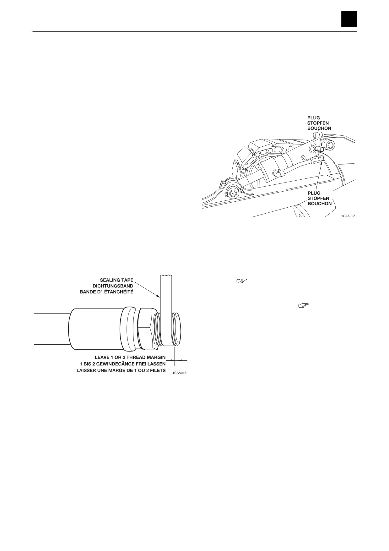
Be sure to install caps or plugs on all openings in the
b. Reason for repair, repair history.
hydraulic unit to prevent dirt from getting into the unit
c. Are the filters dirty?
through them.
d. The conditions of the fuel and oil.
e. Any damage or looseness to any part?
•
Where necessary, draw alignment indicators to avoid
assembly errors. To avoid misconnection, place indi-
cators such as reference tags on pipes.
•
Clean all disassembled parts and new parts, arrange
them neatly, and place indicators as necessary.
•
Be sure to replace all seals and cotter pins with new
ones.
•
Keep those parts that should not come in contact with
water or oil away from those with oil on the surface.
•
When installing bearings, bushings and oil seals, a
press tool should be used. If a hammer is used, use a
cushioning material to avoid damage.
•
The hydraulic oil adhering to the unit is often mistaken
•
Wipe all joining surfaces clean until there is no dirt or
for an oil leak, so wipe off the unit thoroughly.
dust adhering to them.
•
Be sure that no damage is caused to the plating on the
•
Wrap the thread tight with seal tape starting 1 or 2
rod in the hydraulic cylinder.
threads away from the thread end. The tape should be
•
Removal and installation of the hydraulic cylinder
overlapped by about 10 mm (0.39 in).
should be done with the rod fully retracted.
•
Be sure to bleed the air after installing the hydraulic
cylinder. (
“4. Disassembly and assembly: Cylin-
der”)
•
Always bleed the air when hydraulic oil is changed or
a hydraulic device is replaced.(
“4. Disassembly
and assembly: Drive system”)
1-9
SAFETY
CAUTIONS WHEN WORKING 1
When connecting/disconnecting the hoses or
Handling of seals
pipes
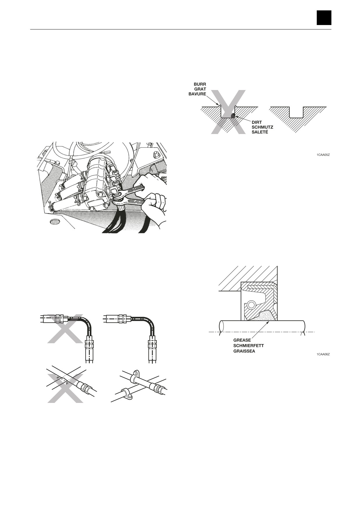
• Clean the grooves for O-rings and remove any burrs.
• When hydraulic hoses or pipes are connected, tighten
them once to the prescribed torque, then loosen them
slightly and retighten them to the prescribed torque.
a. Tighten the fittings after the installation surfaces fit
snugly together.
b. The above procedures do not apply to fittings with
seal tape.
• Use two spanners, one to tighten/loosen and the other
to secure the mating hose/pipe to ensure that the hose
is not twisted.
• Be careful not to twist the O-rings. If twisted, remove it
with your fingertips.
• When inserting, be careful not to damage the seal.
• Handling of the floating seal
a. After removal, wipe all oil off the O-ring and housing
of the floating seal.
b. When assembling, apply a thin coating of gear oil to
the contact surface of the housing,
c. After assembly, turn the seal two or three times to
get it to fit snugly.
1CAA03Z
• Apply grease to the lip of the oil seal.
• After connecting the hydraulic hoses or pipes, apply
a. This is to prevent wear from occurring upon first
the maximum working pressure five or six times to
start up after assembly.
check for leakage.
• If high pressure, vibration or shock is applied to a twist-
ed hose, oil leak, hose breakage or damage to the
hose fitting can result.
• Be sure that the hydraulic hoses are not contacting
sharp objects or each other. This could cause surface
flaws on the hoses, resulting in breakage.
1CAA04Z
1-10
2
SERVICE DATA
Dimensional drawing
Specification tables
Table of masses
Lubricant and fuel chart
Performance criteria
Tightening torque
Hydraulic circuit diagram
Electrical circuit diagram
Wire harness diagram
SERVICE DATA
2
DIMENSIONAL DRAWING
DIMENSIONAL DRAWING
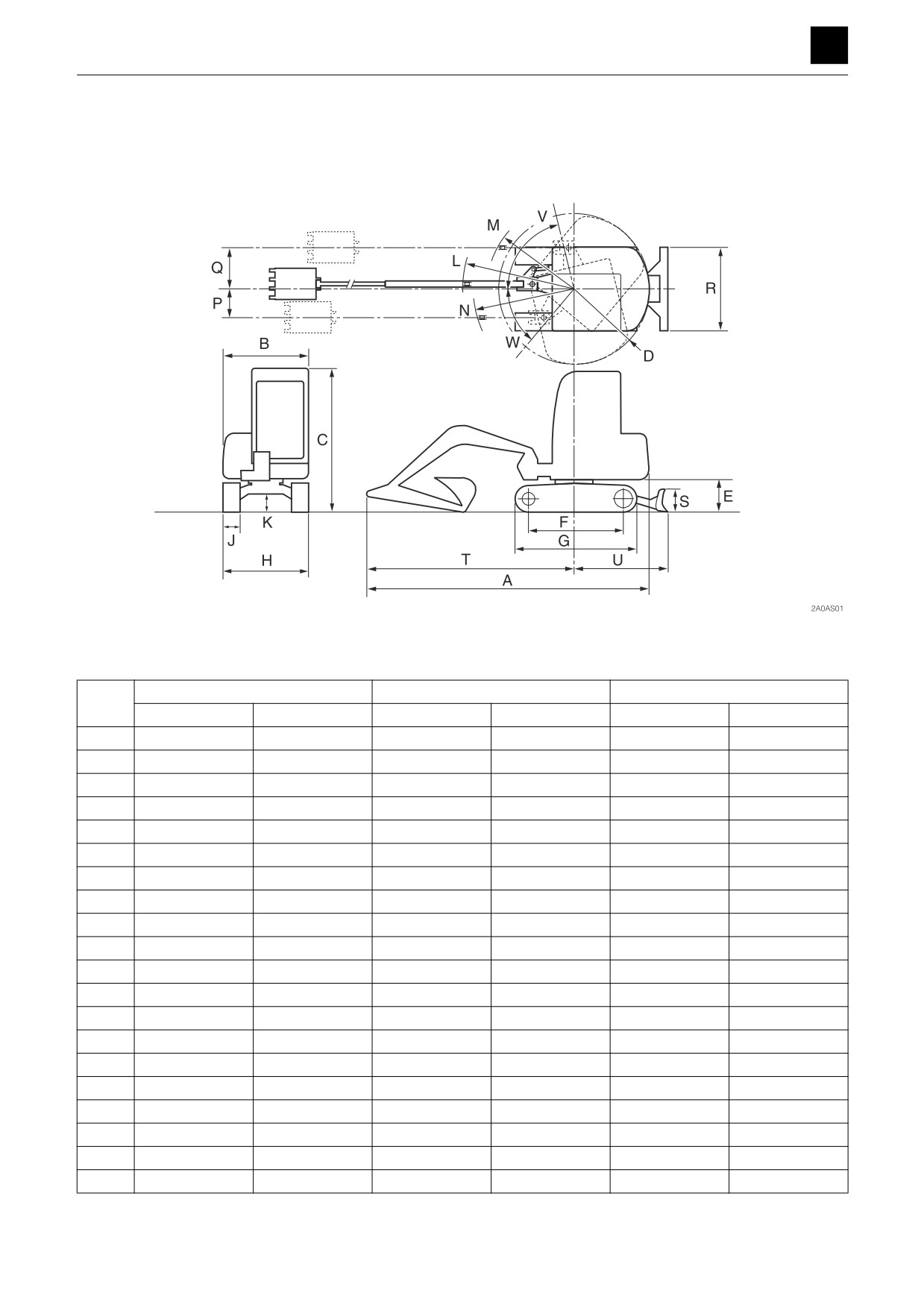
Machine dimensions
Unit: mm (in.)
Standard arm
Middle arm
Long arm
Rubber crawler
Steel crawler
Rubber crawler
Steel crawler
Rubber crawler
Steel crawler
A
7725 (304.1)
I
7780 (306.2)
I
7815 (307.6)
I
B
2460 (96.9)
I
I
I
I
I
C
2815 (110.9)
2805 (110.4)
2815 (110.9)
2805 (110.4)
2815 (110.9)
2805 (110.4)
D
2000 (78.8)
I
I
I
I
I
E
930 (36.6)
895 (35.3)
930 (36.6)
895 (35.3)
930 (36.6)
895 (35.3)
F
2900 (114.2)
2890 (113.9)
2900 (114.2)
2890 (113.9)
2900 (114.2)
2890 (113.9)
G
3615 (142.4)
3600 (141.7)
3615 (142.4)
3600 (141.7)
3615 (142.4)
3600 (141.7)
H
2490 (98.0)
I
I
I
I
I
J
500 (19.7)
I
I
I
I
I
K
475 (18.6)
440 (17.4)
475 (18.6)
440 (17.4)
475 (18.6)
440 (17.4)
L
2885 (113.5)
I
2965 (116.8)
I
3015 (118.6)
I
M
2285 (90.0)
I
2360 (93.0)
I
2405 (94.6)
I
P
625 (24.7)
I
I
I
I
I
Q
910 (35.9)
I
I
I
I
I
R
2490 (98.0)
I
I
I
I
I
S
550 (21.7)
I
I
I
I
I
T
5725 (225.3)
I
5780 (227.5)
I
5815 (228.9)
I
U
2410 (95.0)
I
I
I
I
I
V
77°
I
I
I
I
I
W
53°
I
I
I
I
I
1
DIMENSIONAL DRAWING
2A0AS00
SERVICE DATA
2
DIMENSIONAL DRAWING
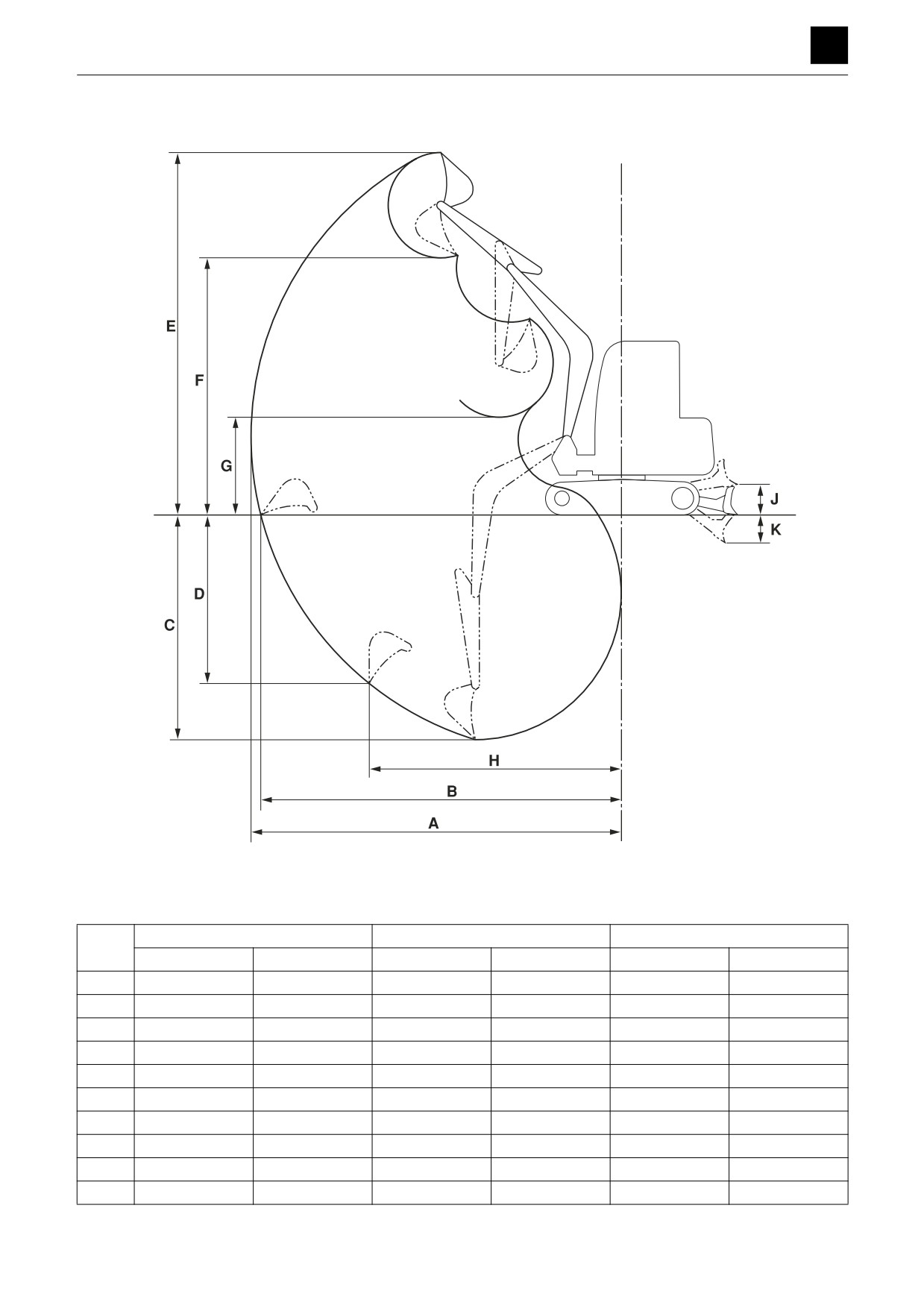
Operating range
2A0AS02
Unit: mm (in.)
Standard arm
Middle arm
Long arm
Rubber crawler
Steel crawler
Rubber crawler
Steel crawler
Rubber crawler
Steel crawler
A
8280 (326.1)
I
8520 (335.4)
I
8755 (344.8)
I
B
8080 (318.1)
8090 (318.4)
8325 (327.7)
I
8570 (337.3)
I
C
4985 (196.3)
5020 (197.6)
5235 (206.2)
5270 (207.5)
5485 (216.0)
5520 (217.3)
D
4135 (162.9)
4170 (164.2)
4375 (172.3)
4410 (173.6)
4620 (181.8)
4650 (183.1)
E
8315 (327.3)
8280 (326.0)
8495 (334.4)
8460 (333.1)
8670 (341.4)
8640 (340.2)
F
5860 (230.8)
5830 (229.5)
6045 (237.9)
6010 (236.7)
6220 (245.0)
6190 (243.7)
G
2340 (92.2)
2310 (90.9)
2105 (82.8)
2070 (81.5)
1855 (73.1)
1825 (71.9)
H
5240 (206.3)
I
5305 (208.8)
I
5365 (211.2)
I
J
540 (21.3)
505 (20.0)
540 (21.3)
505 (20.0)
540 (21.3)
505 (20.0)
K
510 (20.2)
545 (21.5)
510 (20.2)
545 (21.5)
510 (20.2)
545 (21.5)
2
DIMENSIONAL DRAWING
2A0AS00
SERVICE DATA
SPECIFICATION TABLES 2
SPECIFICATION TABLES
Rubber
Canopy
kg ( lb)
-
crawler
Cab
kg (lb)
14850 (32740)
Operating mass
Steel
Canopy
kg ( lb)
-
crawler
Cab
kg (lb)
14850 (32740)
Net (ISO 14396) kW/min-1(hp/rpm)
77/2000(103.3/2000)
Rated output
Net (ISO 9249/SAEJ1349) kW/min-1(hp/rpm)
71.8/2000(96.3/2000)
Heaped capacity
m3 (ft.3)
0.45
( 15.89)
Bucket capacity
Struck capacity
m3 (ft.3)
0.34
( 12.01)
Performance
Standard loading mass
kg ( lb)
610 ( 1345)
Slew speed
i
-1 (rpm)
13.8
(13.8)
Rubber
1st
km/h (mph)
3.0
( 1.9
)
crawler
2nd
km/h (mph)
5.3
( 3.3
)
Travel speed
Steel
1st
km/h (mph)
2.8
(1.76)
crawler
2nd
km/h (mph)
5.0
(3.08)
Maximum tractive force
kN ( lbf)
72.4 ( 16280)
%
70
Gradeability
deg.
35
Rubber
Canopy
kPa ( psi)
-
crawler
Cab
kPa ( psi)
45.3
( 6.57)
Ground pressure
Steel
Canopy
kPa ( psi)
-
crawler
Cab
kPa ( psi)
46.9
( 6.8
)
Sound-power level
dB ( A)
101
Noise level
Sound-pressure
dB (A)
-
level*
*: At the operator location as stipulated by ISO 6396: 2008.
Dimensions of completed machine
Standard arm
mm (in.)
7725 (304.1)
Overall length
Middle arm
mm (in.)
7780 (306.2)
Long arm
mm (in.)
7815 (307.6)
During normal operation
mm ( in.)
2490 ( 98.0)
Overall width
Track retracted
mm ( in.)
-
Rubber
Canopy
mm ( in.)
-
crawler
Cab
mm (in.)
2815 (110.9)
Overall height
Steel
Canopy
mm ( in.)
-
crawler
Cab
mm (in.)
2805 (110.4)
Dimensions of base machine
Overall length of base machine
mm (in.)
4140 (163.0)
Overall width of base ma-
During normal operation
mm ( in.)
2490 ( 98.0)
chine
Track retracted
mm ( in.)
-
Upper structure overall width
mm ( in.)
2460 ( 96.9)
Upper structure overall
Left
mm ( in.)
1245 ( 49.0)
width
Right
mm ( in.)
1215 ( 47.8)
Cab overall width
mm ( in.)
1090 ( 42.9)
1
SPECIFICATION TABLES
2B0AS001
SERVICE DATA
2
SPECIFICATION TABLES
Rubber
Canopy
mm (in.)
-
Overall height of base ma-
crawler
Cab
mm (in.)
2815 (110.9)
chine
Steel
Canopy
mm (in.)
-
crawler
Cab
mm (in.)
2805 (110.4)
Swing radius
mm (in.)
2000 (78.8)
Upper structure rearmost distance from axis of rotation
mm (in.)
2000 (78.7)
Clearance height under up-
Rubber crawler
mm (in.)
930 (36.6)
per structure
Steel crawler
mm (in.)
895 (35.3)
Rubber crawler
mm (in.)
2890 (113.7)
Crawler base
Steel crawler
mm (in.)
2880 (113.4)
Rubber crawler
mm (in.)
3605 (141.9)
Crawler overall length
Steel crawler
mm (in.)
3585 (141.2)
Undercarriage overall
During normal operation
mm (in.)
2490 (98.0)
width
Track retracted
mm (in.)
-
During normal operation
mm (in.)
1990 (78.3)
Track gauge
Track retracted
mm (in.)
-
Track shoe width
mm (in.)
500 (19.7)
Ground clearance of un-
Rubber crawler
mm (in.)
475 (18.6)
dercarriage
Steel crawler
mm (in.)
440 (17.4)
Engine
Model
Isuzu 4JJ1X
4-cycle, inline water-cooled overhead cam shaft,
Type
direct-injection, supercharged exhaust turbo
Number of cylinders
Quantity
4
Cylinders
Bore
mm (in.)
95.4
(3.8)
Stroke
mm (in.)
104.9
(4.1)
Total displacement
mL (cu. in.)
2999 (183)
N·m (ft.-lb.)
385 (284)
Maximum torque
min-1 (rpm)
1600 (1600)
g/(kW·h)
Specific fuel consumption (at rated output)
213 (0.350)
(lb./hp-hr.)
Fuel/air cleaner
Filter paper-type
Fan
Feed supply system
Cooling system
Radiator
Pressurized
Voltage
V
24
Starting system
Output
kW
4.0
Voltage
V
24
Generator
Output
kW
1.2
Voltage
V
12
Battery
Capacity
A·h
80
Quantity
2
2
SPECIFICATION TABLES
2B0AS00
SERVICE DATA
2
SPECIFICATION TABLES
Hydraulic system
Hydraulic pump drive system
Engine-linked
Type
Double variable piston pump and 2 gear pumps
Quantity
1
L/min.
112 (29.6)
(US gal./min.)
L/min.
112 (29.6)
Hydraulic pump
(US gal./min.)
Delivery
L/min.
54.8
(14.5)
(US gal./min.)
L/min.
20 (5.3)
(US gal./min.)
Hydraulic pump control system
Total horsepower control
MPa (psi)
34.3 (4970)
MPa (psi)
-
Main relief valve pressure setting
MPa (psi)
-
MPa (psi)
-
Hydraulic tank pressure
Pressure tank
Type
Directional control valve with 12 valves in series
Control valve
Operation type
-
Type
Glass fiber filter type
Hydraulic oil filter
Filter precision
BETA 10 = 6.0
Installation position
Return circuit (inside tank)
Cooling system
Air-cooled
Hydraulic oil cooler
Radiation surface area
m2 (ft.2)
-
Operating device
Position
Left side
Cab
Construction
Suspension seat, adjustable
Steel-enclosed cab
Cab or canopy
Construction
with fully reinforced glass windows
Variable travel speed switch
Shifting operation
(handle grip of operating lever)
Travel operation
Hydraulic pilot operated, 2 levers
Slew operation
Hydraulic pilot-operated
Control levers and pedals
Arm operation
Hydraulic pilot-operated
Bucket operation
Hydraulic pilot-operated
Boom operation
Hydraulic pilot-operated
Boom swing operation
Hydraulic pilot-operated pedal system
Other
Auxiliary line piping operation: Switch operated
Water temperature gauge, fuel gauge, engine emer-
gency warning light, third hydraulic line, charge warn-
Instruments, switches
Cluster gauges
ing light, hydraulic pressure warning light, water tem-
perature warning light, variable-speed travel indicator
Headlight
V-W
24-70 H3 halogen
Lighting device
Boom light
V-W
24-70 H3 halogen
Warning, safety devices
24 V, 113 dB (A)
With AUX IN AM/FM radio, air conditioner, wipers,
Others
and defroster
3
SPECIFICATION TABLES
2B0AS00
SERVICE DATA
2
SPECIFICATION TABLES
Slew equipment
Slew bearing
Type
Ball bearing-typ e
Type
Constant-volume, swash plate piston motor
Slew motor
Quantity
1
Reduction gears
Type
Epicyclic gearing (2-stage)
Type
Counterbalance valveless type, with make-up valve
Slew brake
Quantity
1
Slew parking brake
Type
Wet, friction plate typ e
Slew lock
Type
-
Lower machinery
Power transmission device
Variable displacement (2-speed) piston motor, with
Type
Travel motor
counterbalance valve
Quantity
2
Reduction gears
Type
Epicyclic gearing (2-stage)
Travel brake
Type
Brake valve with shockless relief
Parking brake
Type
Wet, friction plate typ e
Undercarriage
Type
Rubber crawler
Number of shoes
Quantity
-
(on one side)
Shoe width
mm (in.)
500 (19.7)
Lug height
mm (in.)
35 (1.3)
Track shoe
Type
Steel crawler with triple grouser
Number of shoes
Quantity
44
(on one side)
Shoe width
mm (in.)
500 (19.7)
Grouser height
mm (in.)
20 (0.8)
Carrier roller
Quantity
1
(on one side)
Roller
Track roller
Quantity
7
(on one side)
Track adjuster
Type
Hydraulic cylinder type (with cushion spring)
Track gauge extension mechanism
-
Working equipment
Backhoe attachment
Heaped capacity
m3 (ft.3)
0.45
(15.89)
Bucket capacity
Struck capacity
m3 (ft.3)
0.34
(12.01)
Standard
mm (in.)
850 (33.5)
Bucket width
With side cutter
mm (in.)
970 (38.2)
Bucket mass
kg (lb)
305 (672)
Boom length
mm (in.)
4060 (159.8)
Standard
mm (in.)
2070 (81.5)
Arm length
Middle
mm (in.)
2320 (91.3)
Long
mm (in.)
2570 (101.2)
Bucket wrist radius
mm (in.)
1230 (48.2)
Bucket wrist angle
deg
180
4
SPECIFICATION TABLES
2B0AS00
SERVICE DATA
2
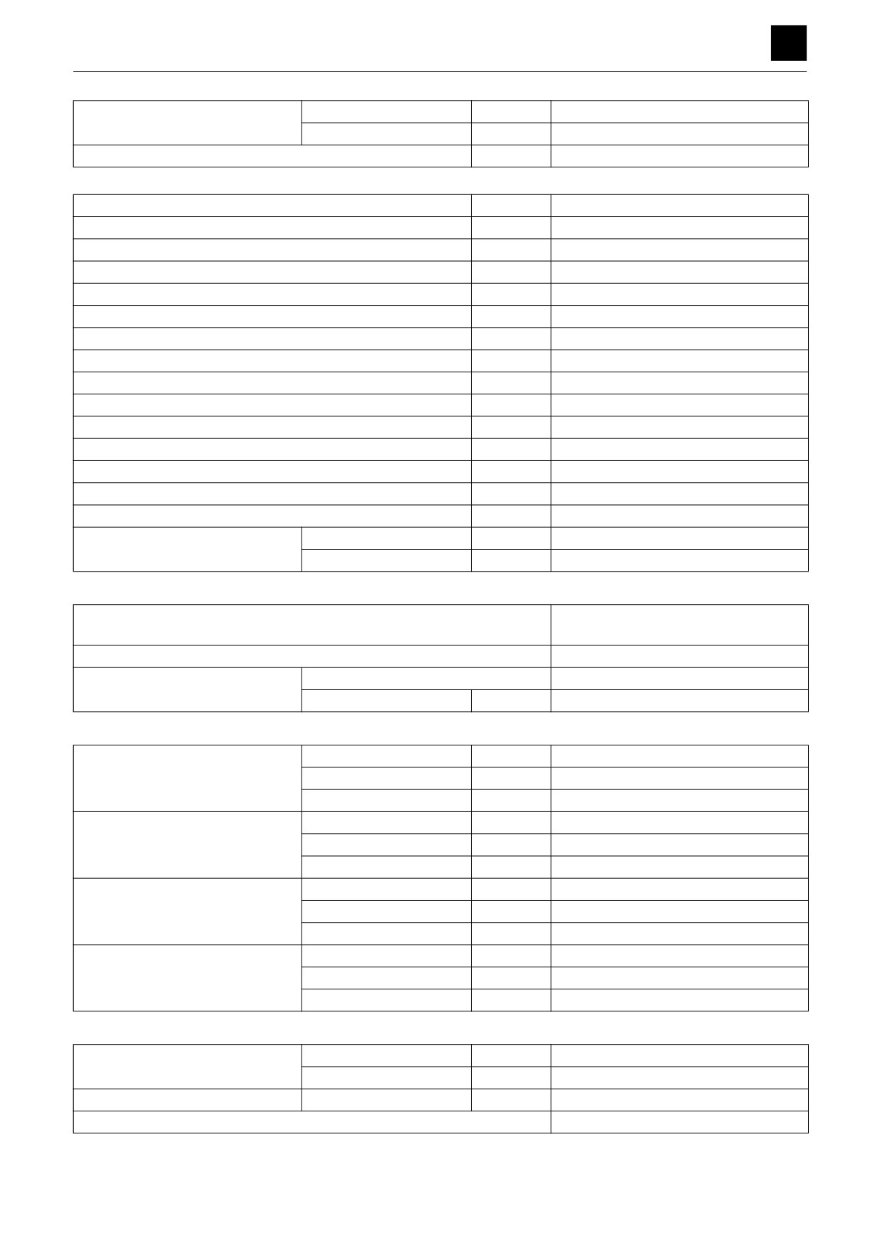
SPECIFICATION TABLES
Left
deg.
75
Boom swing angle
Right
deg.
55
Eccentricity of boom swing pivot
mm (in.)
150 (5.9)
Working dimensions (Standard arm)
Maximum reach
mm (in.)
8280 (326.1)
Maximum reach at ground reference plane
mm (in.)
8080 (318.1)
Minimum radius of ground level finishing
mm (in.)
8565 (337.2)
Maximum digging depth
mm (in.)
4985 (196.3)
Reach at maximum digging depth
mm (in.)
3350 (131.8)
Maximum vertical digging depth
mm (in.)
4135 (162.9)
Maximum height of cutting edge
mm (in.)
8315 (327.3)
Reach at maximum height
mm (in.)
3760 (148.0)
Maximum dumping height
mm (in.)
5860 (230.8)
Reach at maximum dumping height
mm (in.)
3760 (148.0)
Minimum dumping height
mm (in.)
2340 (92.2)
Minimum radius of equipment and attachment
mm (in.)
2885 (113.5)
Minimum radius of equipment at maximum front offset
mm (in.)
2285 (90.0)
Overall height at minimum radius of equipment and attachment
mm (in.)
6260 (246.5)
Overall height of equipment at maximum front offset
mm (in.)
6260 (246.5)
Left
mm (in.)
625 (24.7)
Max. bucket offset distance
Right
mm (in.)
910 (35.9)
Main structure
Integrated hydraulic cylinder,
Boom
drive swing type
Arm
-
Type
-
Bucket
Number of teeth
Quantity
5
Hydraulic cylinder
Number of cylinders
Quantity
2
Boom cylinder
Bore
mm (in.)
100 (3.9)
Stroke
mm (in.)
995 (39.2)
Number of cylinders
Quantity
1
Arm cylinder
Bore
mm (in.)
110 (4.3)
Stroke
mm (in.)
1105 (43.5)
Number of cylinders
Quantity
1
Bucket cylinder
Bore
mm (in.)
100 (3.9)
Stroke
mm (in.)
875 (34.5)
Number of cylinders
Quantity
1
Swing cylinder
Bore
mm (in.)
140 (5.5)
Stroke
mm (in.)
835 (32.9)
Digging force
Bucket cylinder
kN (lbf)
98.7 (22190)
Maximum digging force
Arm cylinder
kN (lbf)
64.9 (14590)
Maximum lifting force
Boom cylinder
kN (lbf)
59.8 (13440)
Attachment (optional)
Long arm, middle arm
5
SPECIFICATION TABLES
2B0AS00

SERVICE DATA
2
SPECIFICATION TABLES
Dozer blade
Type
Straight type
Operation type
Hydraulic hoisting type
Number of cylinders
Quantity
2
Dozer blade cylinder
Bore
mm (in.)
115 (4.5)
Stroke
mm (in.)
235 (9.3)
Dimensions
Width
mm (in.)
2490 (98.0)
Dozer blade dimensions
Height
mm (in.)
550 (21.7)
Cutting angle
deg.
60
Distance between the front end of the dozer blade and the axis
mm (in.)
2395 (94.4)
of rotation
Dozer blade maximum lifting
mm (in.)
540 (21.3)
Dozer blade maximum lowering
mm (in.)
510 (20.2)
Dozer blade approach angle
deg.
30
6
SPECIFICATION TABLES
2B0AS00
SERVICE DATA
2
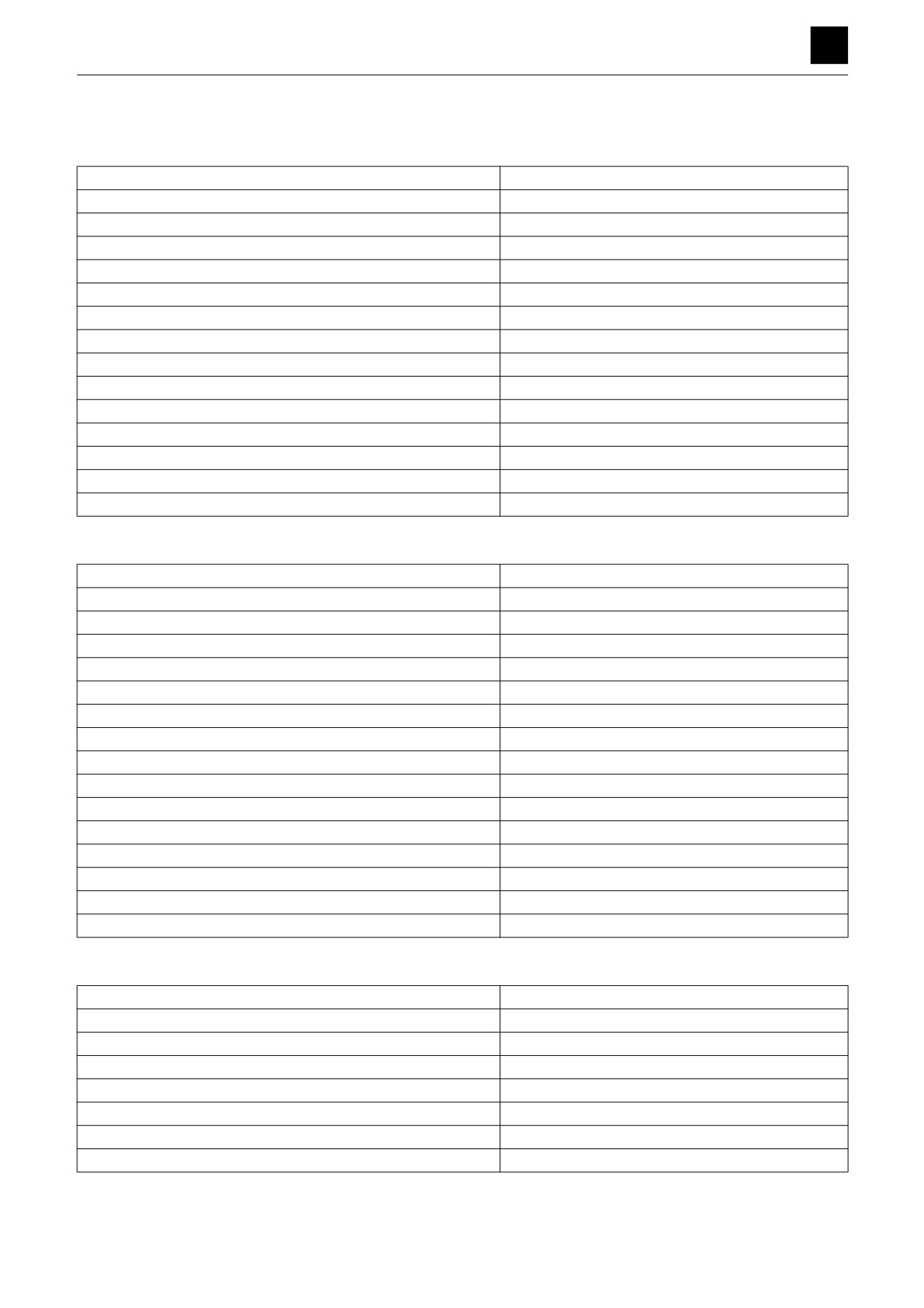
TABLE OF MASSES
TABLE OF MASSES
Upper structure
kg (lb)
Engine
333 (734)
Radiator assembly
81 (179)
Main pump
87 (192)
Gear pump
5 (12)
Hydraulic tank assembly
110 (243)
Fuel tank assembly
82 (180)
Control valve assembly
204 (450)
Pilot valve
2 (5)
Slew motor
170 (375)
Cab
370 (816)
Canopy
-
Counterweight
2250 (4960)
Counterweight (with added weight)
2750 (6063)
Swing bracket
497 (1096)
Swing cylinder
188 (414)
Lower structure
kg (lb)
Swivel joint
24 (53)
Slew bearing
200 (441)
Rubber crawler
752 (1658)
Steel crawler (500-mm-wide model)
750 (1654)
Steel crawler (600-mm-wide model)
895 (1974)
Steel crawler (700-mm-wide model)
992 (2187)
Segmented rubber crawler
812 (1790)
Travel motor
145 (320)
Carrier roller
16 (34)
Track roller
24 (53)
Front idler assembly
103 (226)
Track adjuster
97 (213)
Blade (500-mm-wide model)
567 (1250)
Blade (600-mm-wide model)
578 (1274)
Blade (700-mm-wide model)
590 (1300)
Dozer blade cylinder
61 (134)
Hoe attachment
kg (lb)
Boom
669 (1474)
Arm (standard model)
273 (602)
Arm (middle model)
312 (688)
Arm (long model)
343 (756)
Bucket (Standard model)
305 (672)
Boom cylinder
110 (243)
Arm cylinder
137 (302)
Bucket cylinder
94 (207)
1
TABLE OF MASSES
2B1AS00
SERVICE DATA
2
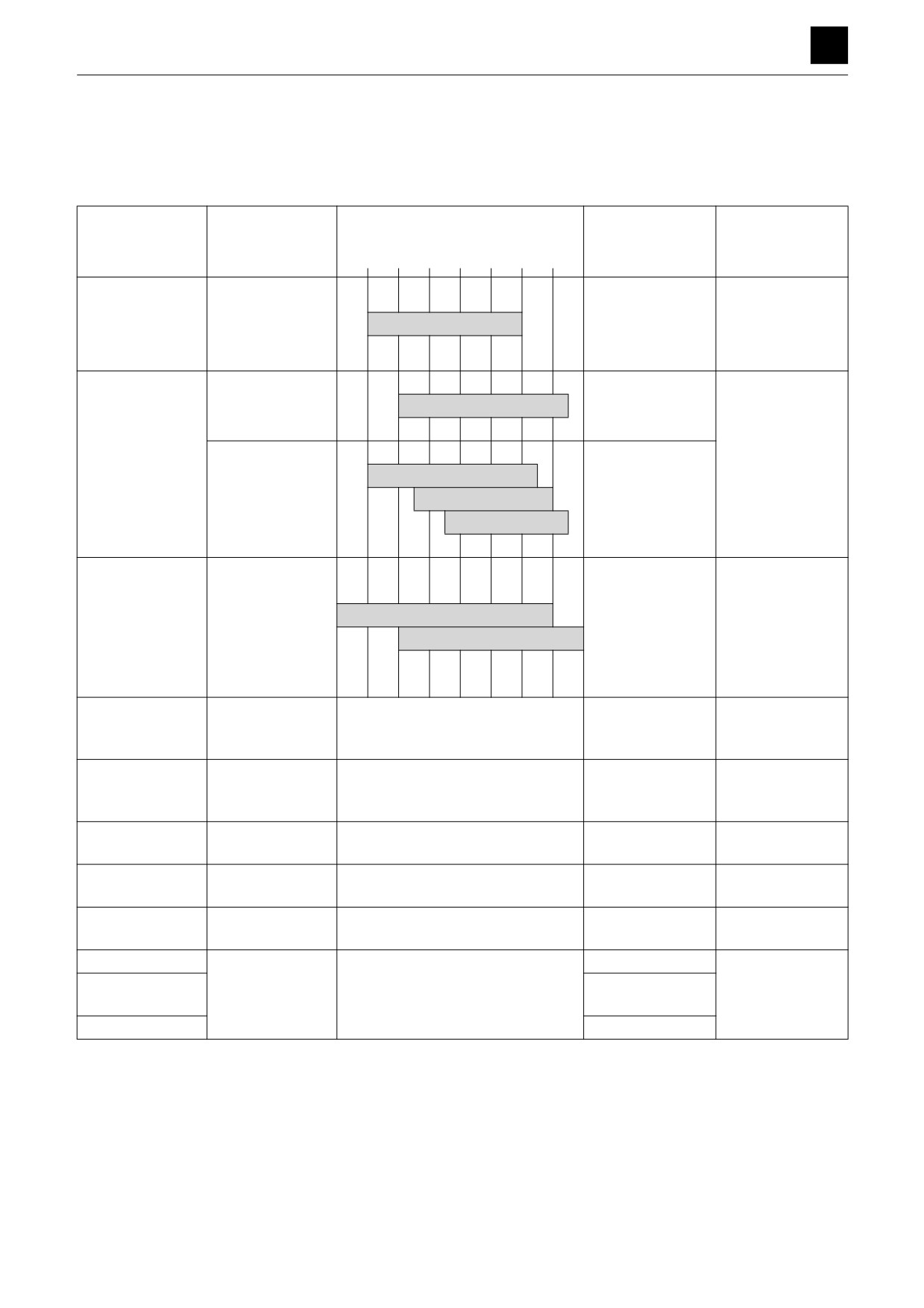
LUBRICANT AND FUEL CHART
LUBRICANT AND FUEL CHART
Select the appropriate fuel, lubricant, and grease according to temperature by referring to the table below.
• Regardless of the specified time, change the oil if it becomes too dirty or degraded.
• When refilling, never mix oils of different brands. If a brand is to be changed, replace all of the fuel/oil.
Selection by air temperature
When to change/
Part
Type
-4
14
32 50
68
86 104°F
Capacity
replenish
-20
-10
0
10
20
30
40°C
Upper limit:
Diesel engine oil
Every 500 hrs. af-
17 L (18.0 US qt.)
Engine oil pan
SAE 10W-30
API: CJ-4
ter the first 50 hrs.
Lower limit:
13 L (13.7 US qt.)
Takeuchi genuine
ISO VG46
Every 4000 hrs.***
hydraulic oil 46
Total amount of oil:
215 L (56.8 US gal.)
Hydraulic tank
ISO VG32
Tank capacity:
Anti-wear hydrau-
95 L (25.1 US gal.)
ISO VG46
Every 2000 hrs.***
lic oil
ISO VG68
Cooling water
(water + coolant)**
SAE-J814C,
Engine cooling
Mixture of 50% coolant
J1941, J1034, or
Every 1000 hrs.
18.5 L (19.5 US qt.)
system
Mixture of 30% coolant
J2036
ASTM-D6210 or
D4985 (USA)
Every 1000 hrs.
Slew reduction
Gear oil
SAE 90
after the first 250
5.3 L (5.6 US qt.)
gear
API: GL-4
hrs.*
Every 1000 hrs.
Travel reduction
Gear oil
SAE 90
after the first 250
2.1 L (2.2 US qt.)
gear
API: GL-4
hrs.*
Engine oil
Carrier roller
SAE 30
-
0.05 L (1.7 fl. oz.)
API: CD class
Gear oil
Track roller
ISO VG 220
-
0.29 L (9.8 fl. oz.)
API: GL-3
Engine oil
Idler
SAE 10W-30
-
0.20 L (6.8 fl. oz.)
API: CD class
Slew bearing
Every 500 hrs.
Lithium grease
Working equip-
Daily or every 10
EP-2
-
As required
ment
hrs.
NLGI No. 2
Levers
When required
If the ratio of traveling time to total operating time is high, replace the gear oil earlier than the specified time.
**
For water, use tap water (soft). Do not use well or river water.
When the ambient temperature drops below 0°C (32°F), add coolant (antifreeze). Follow the coolant manufactur-
er’s instructions to determine the mixture ratio.
*** The replacement interval for hydraulic oil depends on the type of oil being used. New machines are shipped from
the factory with the Takeuchi genuine hydraulic oil 46. This manual describes when to replace the hydraulic oil
assuming that this Takeuchi oil is used. When a conventional anti-wear hydraulic oil is used, replace it every 2000
hours.
1
LUBRICANT AND FUEL CHART
2C0AS00

SERVICE DATA
2
LUBRICANT AND FUEL CHART
Diesel fuel standards
Use a diesel fuel that is compliant with any of the stan-
dards listed below. The table below shows standards
from various countries/regions.
Diesel fuel standards
Country/Region
ASTM D975
USA
No. 1-D, S15, S500
Canada
No. 2-D, S15, S500
EN590:96
EU
ISO 8217 DMX
International standard
BS 2869-A1 (or A2)
UK
JIS K2204 Grade, 2-go
Japan
KSM-2610
Korea
GB252
China
Part
Type
Capacity
To maintain the performance and service life of the engine,
always use clean and high-quality fuel.
• To avoid freezing in cold climates, use a light oil that still
functions when the temperature is at least 12°C (54°F) be-
low the lowest expected ambient temperature.
• Use a light oil with a cetane number of 45 or higher. When
operating at a very low temperature or at a high altitude, a
higher cetane number fuel will be required.
• Use fuel with an overall sulfur content below 0.05% to
Fuel tank
Diesel fuel
0.0015%. Be sure to use fuel with an ultra-low sulfur con-
250 L (66.0 US gal.)
tent for applications in the U.S. or Canada, in particular.
• The use of fuel containing a high sulfur content may cause
sulfuric acid corrosion to occur inside the cylinder.
• Do not mix fuel with any kerosene, used engine oil, or left-
over fuel.
• Poor quality fuel can degrade engine performance. It can
also damage the engine.
• Refrain from adding additives to the fuel. Some fuel addi-
tives can degrade engine performance.
2
LUBRICANT AND FUEL CHART
2C0AS00
SERVICE DATA
2
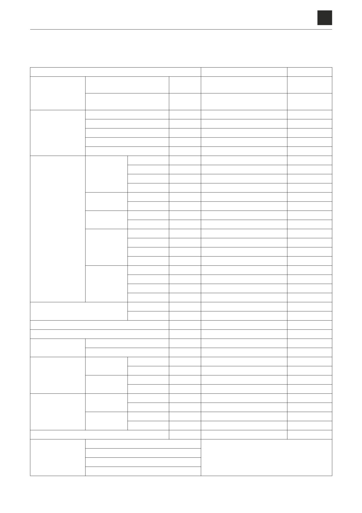
PERFORMANCE CRITERIA
PERFORMANCE CRITERIA
Standard values table
Item
Standard value
Allowable value
min-1
+20
+20
Idling
1000
-20
(
1000
-20
)
(rpm)
Engine speed
min-1
+20
+20
Maximum R.P.M.
2000
-20
(
2000
-20
)
(rpm)
Boom
MPa (psi)
+1.4
(
+203
)
34.3
-0.5
4975
-73
Arm
MPa (psi)
+1.4
(
+203
)
34.3
-0.5
4975
-73
Hydraulic oil pres-
+1.8
+261
Dozer blade
MPa (psi)
23.5
-0.5
(
3408
-73
)
sure
+2.8
+406
Slew
MPa (psi)
32.4
-0
(
4699
-0
)
+0.5
+73
Pilot pressure
MPa (psi)
3.9
-0.1
(
566
-15
)
+0.5
Retracted
s
3.2
-0.5
4.0
+0.5
Extended
s
2.8
-0.5
3.6
Boom cylinder
Retracted
s
Extended
s
+0.5
Retracted
s
2.8
-0.5
3.6
Arm cylinder
+0.5
Extended
s
3.0
-0.5
3.8
+0.4
Bucket cylin-
Retracted
s
2.1
-0.4
2.7
+0.4
der
Extended
s
3.1
-0.4
3.8
Cylinder speed
+1.2
Retracted
s
9.2
-1.2
11.3
+1.2
Extended
s
9.3
-1.2
11.4
Swing cylinder
Retracted
s
Extended
s
+0.4
Retracted
s
3.5
-0.4
4.3
+0.5
Dozer blade
Extended
s
4.2
-0.5
5.1
cylinder
Retracted
s
Extended
s
+0.8
Normal speed
s
9.2
-0.8
10.9
Slew time
Low speed
s
+150
+5.9
Overrun when slewing stops
mm (in.)
500
-150
(
19.7
-5.9
)
865 (34.1)
Natural travel drop
mm (in.)
0
(
0
)
Slew bearing
mm (in.)
0
(
0
)
Natural slew drop
+0
+0.0
Swing cylinder
mm (in.)
10
-10
(
0.4
-0.4
)
20 (0.8)
+1.4
Rubber
s
11.4
-1.4
13.9
1st
+1.7
Travel speed 10 m
Steel
s
12.0
-1.7
14.9
+1.2
(32.8 ft.)
Rubber
s
6.6
-1.2
8.7
2nd
+1.4
Steel
s
6.9
-1.4
9.3
+3.0
Rubber
s
44.3
-3.0
51.7
1st
+3.0
Travel speed
Steel
s
47.5
-3.0
55.3
+2.5
(5 revs.)
Rubber
s
25.9
-2.5
32.0
2nd
+2.5
Steel
s
27.8
-2.5
34.2
+0
+0
Straight-ahead traveling
mm (in.)
100
-100
(
19.7
-3.9
)
400 (15.7)
Bucket
Straight travel func-
Arm
To be moved forward using simultaneous
tion check
Boom
operation
Dozer blade
1
PERFORMANCE CRITERIA
2D0AS00

SERVICE DATA
2
PERFORMANCE CRITERIA
+1.1
Bucket cylinder speed
Retracted
s
4.3
-1.1
5.8
+0
+0.0
Boom cylinder
mm (in.)
4
-4
(
0.2
-0.2
)
8 (0.3)
+0
+0.0
Arm cylinder
mm (in.)
4
-4
(
0.2
-0.2
)
8 (0.3)
Arm cylinder
mm (in.)
(
)
(with emergency shut-off valve)
Natural cylinder
+0
+0.0
Bucket cylinder
mm (in.)
4
-4
(
0.2
-0.2
)
8 (0.3)
drop
Dozer blade cylinder
mm (in.)
+0
(
+0.0
)
4
-4
0.2
-0.2
8 (0.3)
Bucket tip
mm (in.)
+0
(
+0.0
10
-10
0.4
-0.4
)
20 (0.8)
Bucket tip
mm (in.)
(
)
(with emergency shut-off valve)
+0
+0.0
Backlash
mm (in.)
10
-10
(
0.4
-0.4
)
20 (0.8)
+0
+0.0
Right control lever
mm (in.)
4
-4
(
0.2
-0.2
)
8 (0.3)
+0
+0.0
Left control lever
mm (in.)
4
-4
(
0.2
-0.2
)
8 (0.3)
Lever play
+0
+0.0
Travel lever
mm (in.)
4
-4
(
0.2
-0.2
)
8 (0.3)
+0
+0.0
Dozer blade lever
mm (in.)
4
-4
(
0.2
-0.2
)
8 (0.3)
Swing lever
N (lbf)
Lever control force
Dozer blade lever
N (lbf)
+0.4
+0.02
Slew bearing play
mm (in.)
0.5
-0.4
(
0.02
-0.02
)
3 (0.1)
Rubber
mm (in.)
155 to 165 (6.1 to 6.5)
Track tension
Rubber pads
mm (in.)
235 to 265 (9.3 to 10.4)
Steel
mm (in.)
250 to 280 (9.8 to 11.0)
2
PERFORMANCE CRITERIA
2D0AS00
SERVICE DATA
2
PERFORMANCE CRITERIA
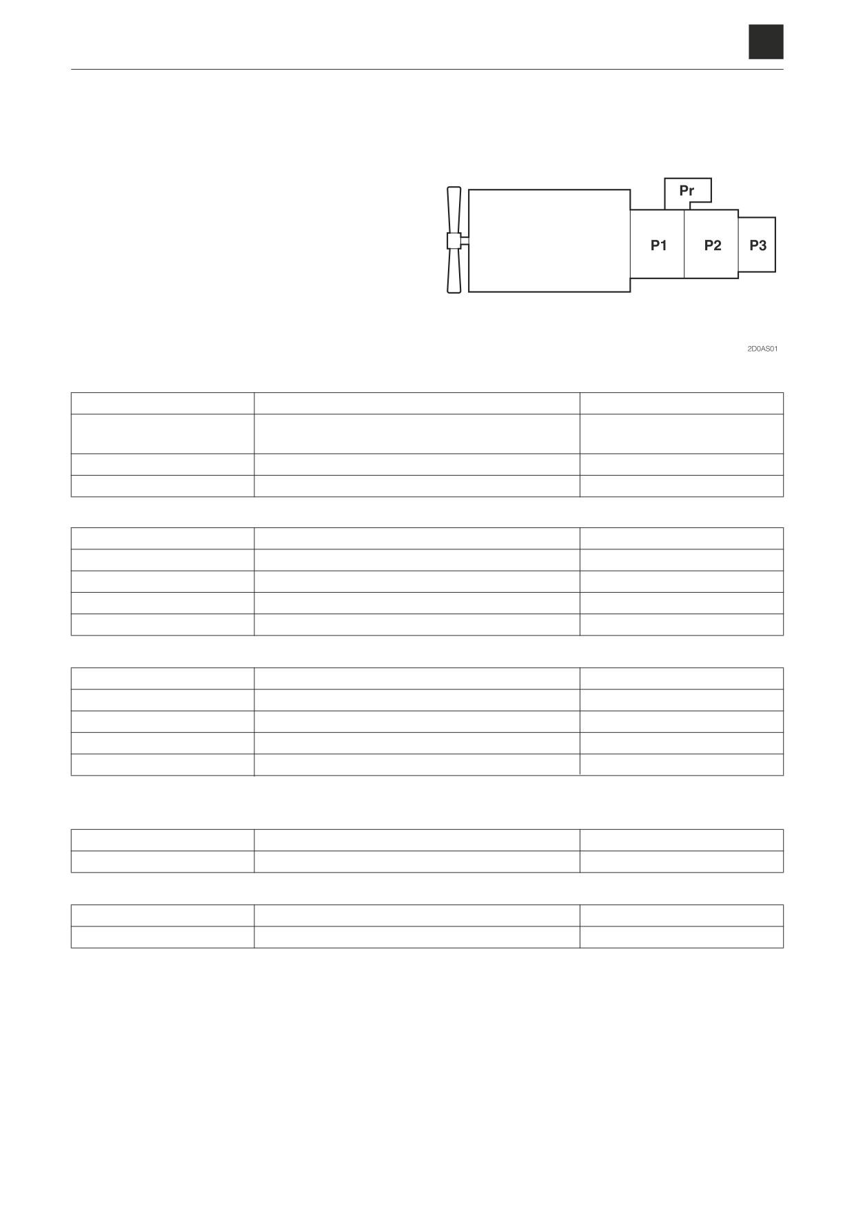
Hydraulic pump assignment table
P1
Right travel, slew, boom, arm, 1st auxiliary line piping
112.0 L/min. (29.6 US gal./min.)
Left travel, bucket, boom, arm, boom swing, 1st aux-
P2
112.0 L/min. (29.6 US gal./min.)
iliary line piping*
P3
Pilot pressure, travel speed switching
20.0 L/min. (5.3 US gal./min.)
Pr
Dozer blade, 2nd auxiliary line piping
54.8 L/min. (14.5 US gal./min.)
Pump P1
Right travel
Pressure: 34.3 MPa (4974 PSI)
Test port
P1
Slew
Pressure: 31.4 MPa (4553 PSI)
Test port
P1
Boom
Pressure: 34.3 MPa (4974 PSI)
Test port
P1
Arm
Pressure: 34.3 MPa (4974 PSI)
Test port
P1
1st auxiliary line piping
Pressure: 24.5 MPa (3553 PSI)
Test port
P1
Pump P2
Left travel
Pressure: 34.3 MPa (4974 PSI)
Test port
P2
Bucket
Pressure: 34.3 MPa (4974 PSI)
Test port
P2
Boom
Pressure: 34.3 MPa (4974 PSI)
Test port
P2
Arm
Pressure: 34.3 MPa (4974 PSI)
Test port
P2
1st auxiliary line piping*
Pressure: 24.5 MPa (3553 PSI)
Test port
P2
Pump P3
Pilot pressure
Pressure: 3.9 MPa (566 PSI)
Test port
P3
Travel speed switching
Pressure: 3.9 MPa (566 PSI)
Test port
P3
Pump Pr
Dozer blade
Pressure: 23.6 MPa (3422 PSI)
Test port P r
2nd auxiliary line piping
Pressure: 23.6 MPa (3422 PSI)
Test port P r
* The first auxiliary line piping is also used for the P2 flow rate in high-flow applications.
3
PERFORMANCE CRITERIA
2D0AS001
SERVICE DATA
2
PERFORMANCE CRITERIA
Methods for inspecting performance
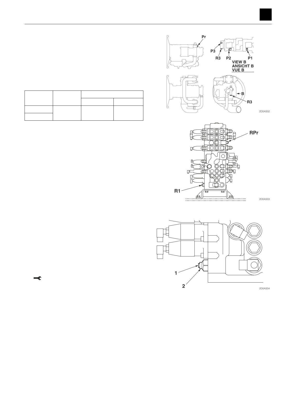
Hydraulic oil pressure (Boom, arm)
Measurement method
• Engine:
Maximum R.P.M.
• Hydraulic oil temp.: 50°C to 60°C (122°F to 140°F)
• Install a pressure gauge on the pressure detection
port. Operate the hydraulic circuit to be tested, and
measure the relief pressure.
Pressure detection port
Circuit
Relief valve
Port
Size
Boom
R1
P1, P2
G1/4
Arm
Adjustment method
1. Loosen the locknut (2), and turn the setscrew (1) to
adjust the set pressure.
• Turn the setscrew clockwise to increase the set
pressure.
• Turn the setscrew counterclockwise to decrease
the set pressure.
2. In order to keep the setscrew (1) from turning after
the pressure has been adjusted, tighten the locknut
(2) while holding the setscrew (1) firmly in place.
Lock nut: 30 ± 2 N·m (22.1±1.5 ft.-lb)
3. Operate the relief valve once more to confirm that the
pressure that has been set is stabilized.
4
PERFORMANCE CRITERIA
2D0AS00
SERVICE DATA
2
PERFORMANCE CRITERIA
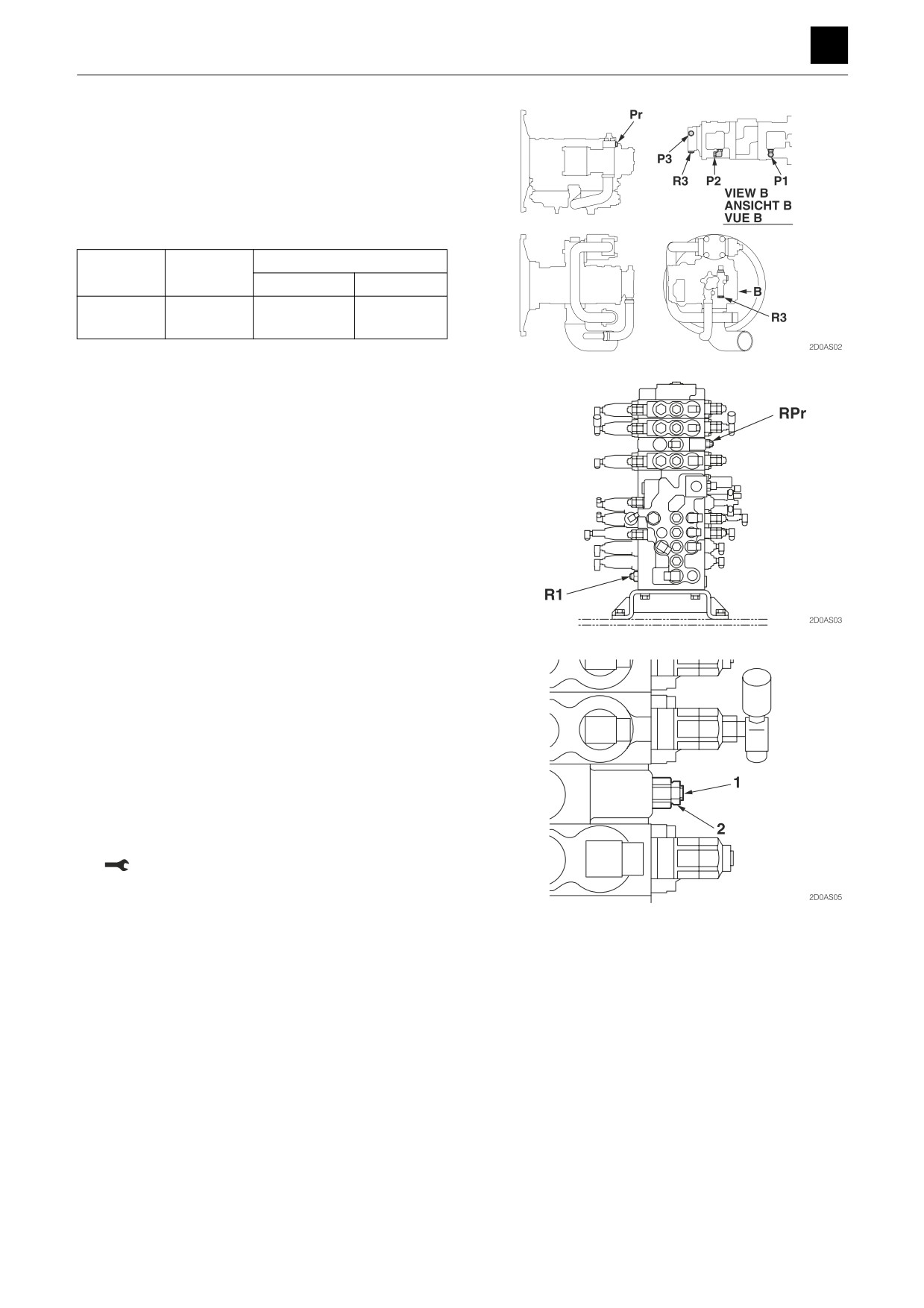
Hydraulic oil pressure (Dozer blade)
Measurement method
• Engine:
Maximum R.P.M.
• Hydraulic oil temp.: 50°C to 60°C (122°F to 140°F)
• Install a pressure gauge on the pressure detection
port. Operate the hydraulic circuit to be tested, and
measure the relief pressure.
Pressure detection port
Circuit
Relief valve
Port
Size
Dozer
RPr
Pr
G1/4
blade
Adjustment method
1. Loosen the locknut (2), and turn the setscrew (1) to
adjust the set pressure.
• Turn the setscrew clockwise to increase the set
pressure.
• Turn the setscrew counterclockwise to decrease
the set pressure.
2. In order to keep the setscrew (1) from turning after
the pressure has been adjusted, tighten the locknut
(2) while holding the setscrew (1) firmly in place.
Lock nut: 30 ± 2 N·m (22.1±1.5 ft.-lb)
3. Operate the relief valve once more to confirm that the
pressure that has been set is stabilized.
5
PERFORMANCE CRITERIA
2D0AS00
SERVICE DATA
2
PERFORMANCE CRITERIA
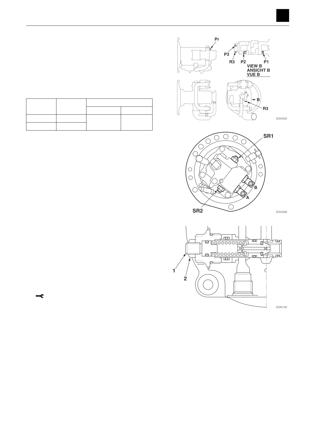
Hydraulic oil pressure (Slew)
Measurement method
• Engine:
Maximum R.P.M.
• Hydraulic oil temp.: 50°C to 60°C (122°F to 140°F)
• Install a pressure gauge on the pressure detection
port. Operate the hydraulic circuit to be tested, and
measure the relief pressure. (Secure the upper struc-
ture so that it cannot slew in the direction to be mea-
sured.)
Pressure detection port
Circuit
Relief valve
Port
Size
Right slew
SR1
P1
G1/4
Left slew
SR2
Adjustment method
1. Loosen the locknut (2), and turn the setscrew (1) to
adjust the set pressure.
• Turn the setscrew clockwise to increase the set
pressure.
• Turn the setscrew counterclockwise to decrease
the set pressure.
2. In order to keep the setscrew (1) from turning after
the pressure has been adjusted, tighten the locknut
(2) while holding the setscrew (1) firmly in place.
Locknut: 49 N·m (36.1 ft.-lb)
3. Operate the relief valve once more to confirm that the
pressure that has been set is stabilized.
6
PERFORMANCE CRITERIA
2D0AS00
SERVICE DATA
2
PERFORMANCE CRITERIA
Hydraulic oil pressure (Pilot pressure)
Measurement method
• Engine:
Maximum R.P.M.
• Hydraulic oil temp.: 50°C to 60°C (122°F to 140°F)
• Install a pressure gauge on the pressure detection
port to measure the relief pressure.
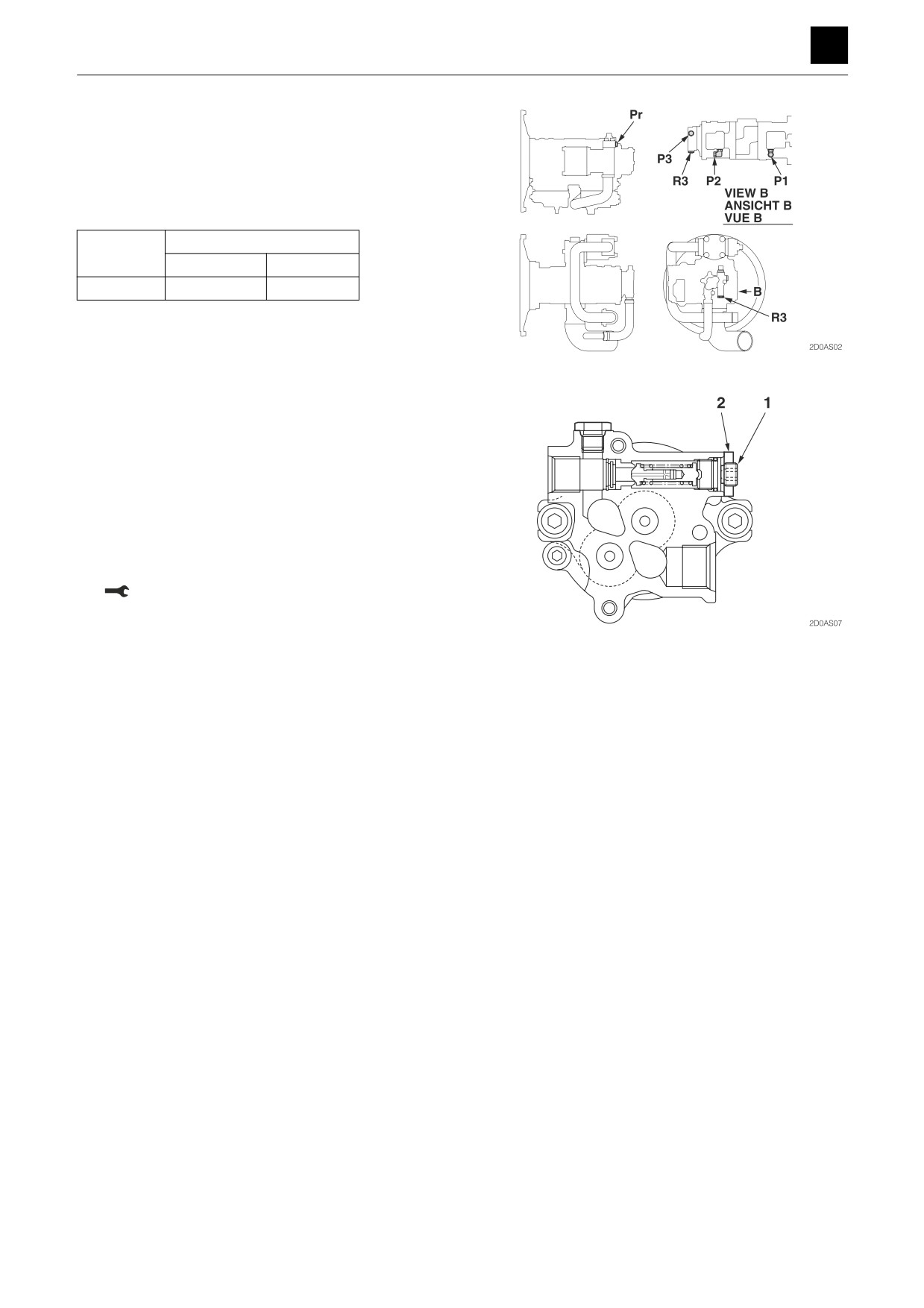
Pressure detection port
Relief valve
Port
Size
R3
P3
G1/4
Adjustment method
1. Loosen the locknut (2), and turn the setscrew (1) to
adjust the set pressure.
• Turn the setscrew clockwise to increase the set
pressure.
• Turn the setscrew counterclockwise to decrease
the set pressure.
2. In order to keep the setscrew (1) from turning after
the pressure has been adjusted, tighten the locknut
(2) while holding the setscrew (1) firmly in place.
Locknut: 29 N·m (21.4 ft.-lb)
3. Operate the relief valve once more to confirm that the
pressure that has been set is stabilized.
7
PERFORMANCE CRITERIA
2D0AS00
SERVICE DATA
2
PERFORMANCE CRITERIA
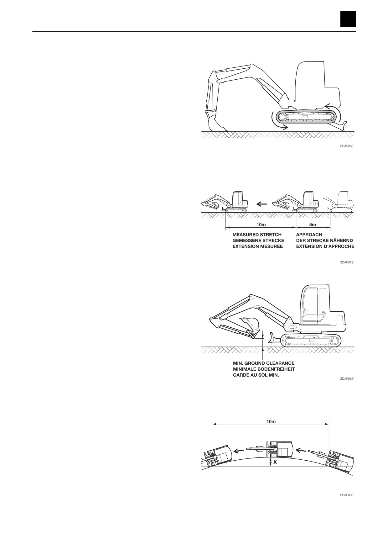
Travel speed (5 revs.)
• Engine:
Maximum R.P.M.
• Hydraulic oil temp.: 50°C to 60°C (122°F to 140°F)
• Measuring attitude: Excavator body to be raised using
both the hoe attachment and the dozer blade
• Set crawler belts in motion. Starting after one full revo-
lution, measure the time required for five revolutions.
(To measure speed after it has stabilized.)
Travel speed (10 m)
• Engine:
Maximum R.P.M.
• Hydraulic oil temp.: 50°C to 60°C (122°F to 140°F)
• Measuring attitude: Traveling
• Drive 5 meters (16.4 ft.) first and then start measuring
the time required for the machine to travel another 10
meters (32.8 ft.). Do this on level ground.
Traveling attitude
With the bucket in a no-load state and the boom raised,
fully extend the arm and bucket cylinders and adjust the
hoe attachment so that its lowest part is even with the ex-
cavator’s minimum ground clearance level. The dozer
blade should not be touching the ground.
Straight-ahead traveling
• Engine:
Maximum R.P.M.
• Hydraulic oil temp.: 50°C to 60°C (122°F to 140°F)
• Measuring attitude: Traveling
• Starting from an approach of 5 meters (16.4 ft.), drive
the excavator in a turn for 10 meters (32.8 ft.), and then
measure the distance, X (from the 5-m point). Do this
on level ground.
8
PERFORMANCE CRITERIA
2D0AS00
SERVICE DATA
2
PERFORMANCE CRITERIA
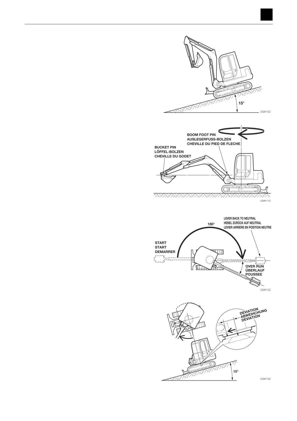
Natural travel drop
• Engine:
Stopped
• Hydraulic oil temp.: 50°C to 60°C (122°F to 140°F)
• Inclination angle:
15°
• Measuring attitude: Fully extend the boom, arm, and
bucket cylinders. Completely retract the dozer blade
cylinder.
• Leave the excavator parked at an angle for 5 minutes
and then measure the amount of natural drop.
Slew time
• Engine:
Maximum R.P.M.
• Hydraulic oil temp.: 50°C to 60°C (122°F to 140°F)
• Measuring attitude: With the bucket in a no-load state,
completely retract the arm cylinders, and then fully ex-
tend the bucket cylinder and make adjustments so that
the boom foot pin and bucket pin are at the same
height.
• Set the upper structure in motion, wait 1 rotation, and
then measure the time required for the next 2 rotations.
Overrun when slewing stops
• Engine:
Maximum R.P.M.
• Hydraulic oil temp.: 50°C to 60°C (122°F to 140°F)
• Measuring attitude: Same as that for measuring slew
time
• Draw matching marks on the outer race of the slew
bearing and the lower frame at points rotated exactly
180° from the starting point. With the hoe attachment
in a no-load state, slew another 180 degrees, at which
point the operation lever should return back to neutral.
Measure the difference between the position marks
and the point at which the hoe attachment was
stopped.
Natural slew drop
• Engine:
Stopped
• Hydraulic oil temp.: 50°C to 60°C (122°F to 140°F)
• Inclination angle:
15°
• Measuring attitude: Same as that for measuring slew
time
• Rotate the upper structure so that it is directly abeam
of the grade. Next, draw positional marks on the outer
race of the slew bearing and on the lower frame. Mea-
sure the amount of distance that opens up between
the marks after 5 minutes have passed.
9
PERFORMANCE CRITERIA
2D0AS00
SERVICE DATA
2
PERFORMANCE CRITERIA
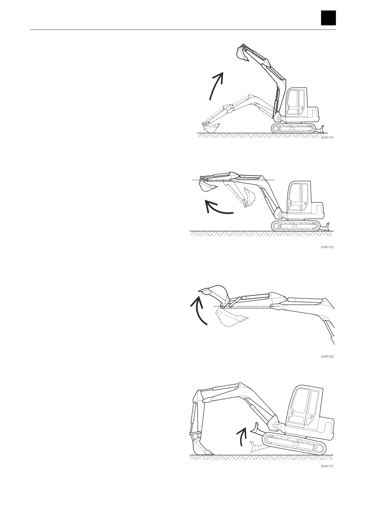
Boom cylinder speed
• Engine:
Maximum R.P.M.
• Hydraulic oil temp.: 50°C to 60°C (122°F to 140°F)
• Measuring attitude: Completely retract the arm cylin-
der, and fully extend the bucket cylinder.
• Next, measure the time required for the bucket to
reach its highest elevation point (lowest point) from its
lowest point (highest point) at rest on the ground. (ex-
clusive of cushion operating time).
Arm cylinder speed
• Engine:
Maximum R.P.M.
• Hydraulic oil temp.: 50°C to 60°C (122°F to 140°F)
• Measuring attitude: With the bucket in a no-load state,
completely retract the arm cylinder, fully extend the
bucket cylinder, position the arm horizontally, and rest
the dozer blade on the ground.
• Measure the time required for the arm cylinder to move
from the fully retracted position to the fully extended
position, and vice versa.
Bucket cylinder speed
• Engine:
Maximum R.P.M.
• Hydraulic oil temp.: 50°C to 60°C (122°F to 140°F)
• Measuring attitude: With the bucket in a no-load state,
completely retract the arm cylinder, position the arm
horizontally, and rest the dozer blade on the ground.
• Measure the time required for the bucket cylinder to
move from the fully retracted position to the fully ex-
tended position, and vice versa.
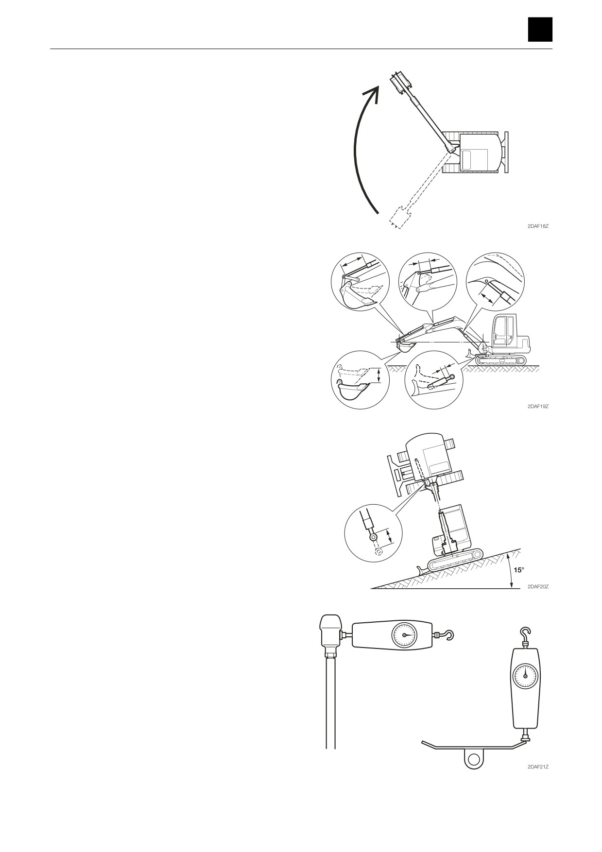
Dozer blade cylinder speed
• Engine:
Maximum R.P.M.
• Hydraulic oil temp.: 50°C to 60°C (122°F to 140°F)
• Measuring attitude: Using the hoe attachment, lift up
the dozer blade end of the excavator.
• After raising and lowering the dozer blade one full
stroke each, measure the time required per stroke in
each direction.
10
PERFORMANCE CRITERIA
2D0AS00
SERVICE DATA
2
PERFORMANCE CRITERIA
Swing cylinder speed
• Engine:
Maximum R.P.M.
• Hydraulic oil temp.: 50°C to 60°C (122°F to 140°F)
• Measuring attitude: Same as that for measuring slew
time
• While swinging the boom from left (right) to right (left),
measure the time required for a full stroke in each di-
rection. (exclusive of cushion operating time).
Natural cylinder drop
Boom, arm bucket, dozer blade, bucket tip
• Engine:
Stopped
• Hydraulic oil temp.: 50°C to 60°C (122°F to 140°F)
• Measuring attitude: With the bucket in a no-load state,
completely retract the dozer blade and arm cylinders,
and then fully extend the bucket cylinder and make
adjustments so that the boom foot pin and bucket pin
are at the same height.
• Maintain this attitude for 5 minutes and then measure
the change in rod length and the distance that the
bucket tip moved.
Swing
• Engine:
Stopped
• Hydraulic oil temp.: 50°C to 60°C (122°F to 140°F)
• Inclination angle:
15°
• Measuring attitude: Same as that for measuring slew
time
• Rotate the upper structure so that it is directly abeam
of the grade, and then measure the change in rod
length after 5 minutes has passed.
Lever operating force
• With the engine turned off, place a push-pull scale on
the handle grip center or the pedal edge to measure
the force. Record the readings at the point at which the
lever/pedal reaches a full stroke.
11
PERFORMANCE CRITERIA
2D0AS001
//////////////////////