Takeuchi Hydraulic excavator TB1140 (Serial No. 514400002~). Operator's Manual - page 6
DISASSEMBLY AND ASSEMBLY
4
HYDRAULIC PUMP (MAIN)
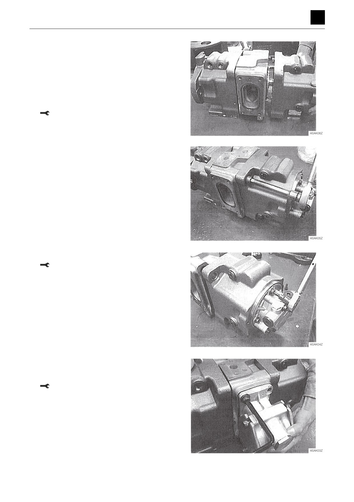
10. Position the pump parallel under the attachment sur-
face for the regulator.
11. Attach the first gear (116) to the block (312).
12. Affix the casings (271) and (272) and the block (312)
in place using cap screws.
• Attach the block so that the regulator is on top and
the intake flange is to the right as viewed from the
front.
Cap screw: 240 N·m
13. Install the gear pump (04).
Cap screw: 17 N·m
14. Insert the PTO unit (05) into the block (312).
• Be sure to insert the PTO unit in the proper direc-
tion.
Cap screw: 33 N·m
8
HYDRAULIC PUMP (MAIN)
4I0AS00
DISASSEMBLY AND ASSEMBLY
4
HYDRAULIC PUMP (MAIN)
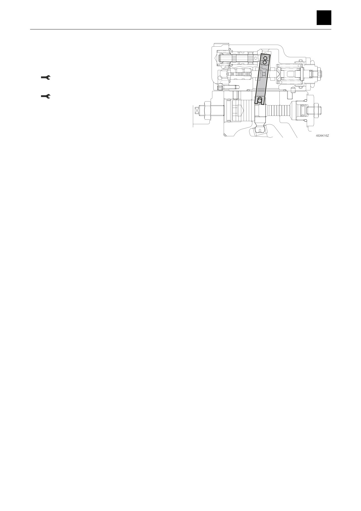
15. Line up the pin (531) so that it fits into the feedback
lever on the regulator, and attach the regulator.
• Take care not to confuse the front and rear regu-
lators.
Cap screw: 29 N·m
16. Insert the plug (468).
Plug: 110 N·m
9
HYDRAULIC PUMP (MAIN)
4I0AS00
DISASSEMBLY AND ASSEMBLY
4
HYDRAULIC PUMP (MAIN)
Inspection and adjustment
Checking the parts
Item
Criteria
Action
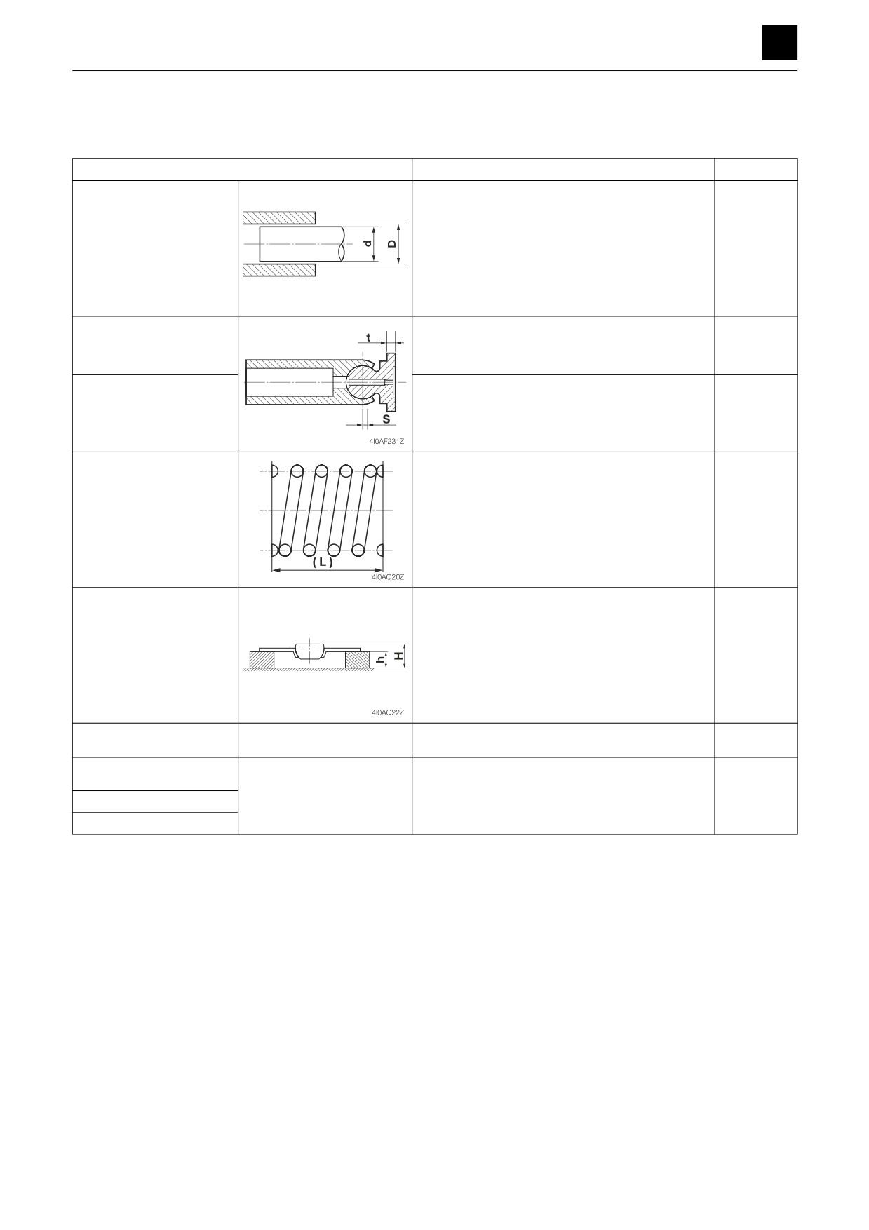
Piston and cylinder block
When the width of the clearance (S) between
Replace
the piston and cylinder block assembly is above
0.056 mm (0.0022 in.)
When there is damage, scratches, abnormal
wear, or other problems present on the surfaces
of sliding parts
S = D-d
4I0AF22Z
Amount of looseness be-
When the amount of looseness (S) between the
Replace
tween the piston and
piston and shoe is above 0.3 mm (0.011 in.)
shoe
Shoe thickness
When the thickness (t) of the shoe is below
Replace
3.7 mm (0.15 in.)
Spring
When the free height of the spring is below
Replace
40.3 mm (1.59 in.)
Plate and bushing as-
When the height (H-h) of the assembled plate
Replace
sembly
and bushing is below 15. 8 mm (0.62 in.)
Seals, O-rings
—
During reassembly after parts disassembled
Replace
Shafts and oil seals
—
When there is abnormal damage, wear, or sei-
Replace
zure on relevant surfaces
Valve plate
Plate
10
HYDRAULIC PUMP (MAIN)
4I0AS00
DISASSEMBLY AND ASSEMBLY
4
HYDRAULIC PUMP (SUB)
HYDRAULIC PUMP (SUB)
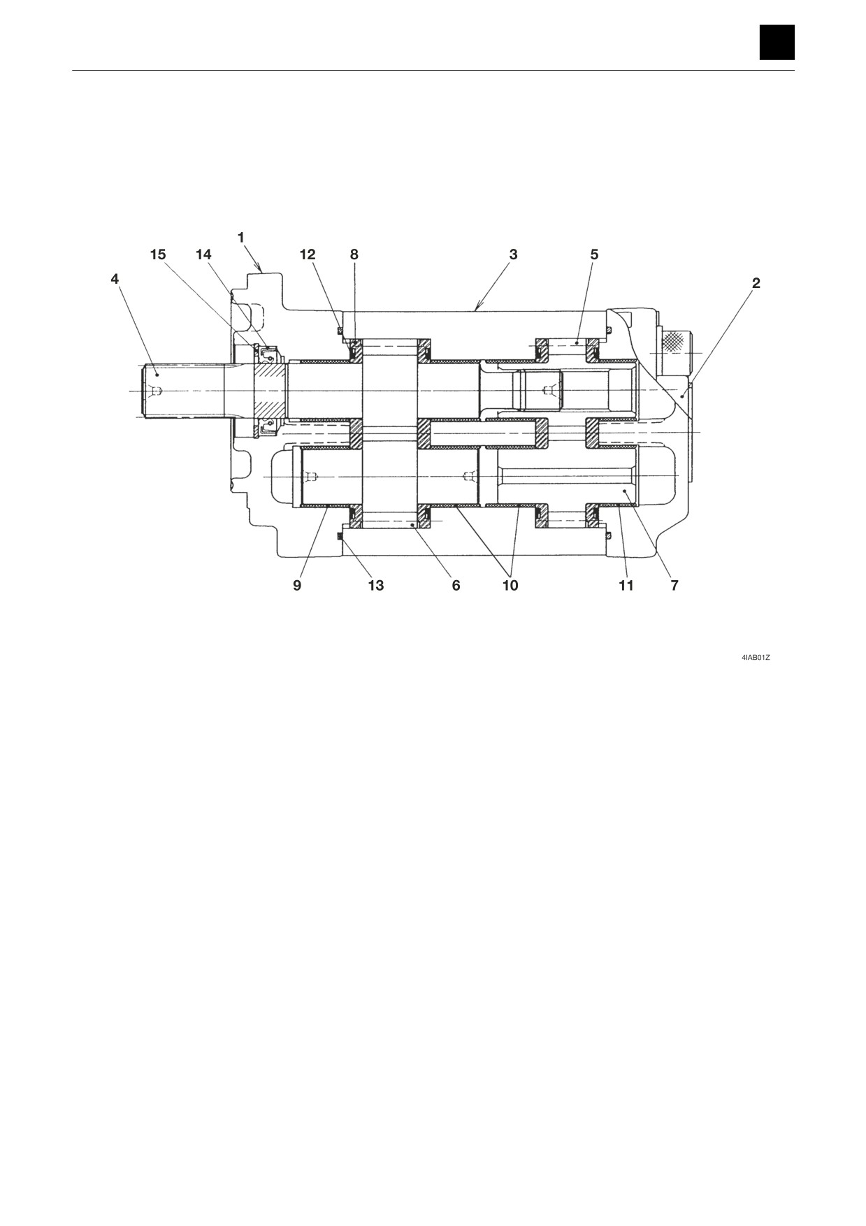
Construction
1. Flange
9. Bushing
2. Rear cover
10. Bushing
3. Housing
11. Bushing
4. Drive gear
12. Gasket
5. Drive gear
13. Gasket
6. Driven gear
14. Oil seal
7. Driven gear
15. Snap ring
8. Bushing
1
HYDRAULIC PUMP (SUB)
4I1AS00
DISASSEMBLY AND ASSEMBLY
4
HYDRAULIC PUMP (SUB)
Disassembly and assembly
The numbers in parentheses, ( ), listed after the names of
parts throughout this document do not necessarily match
the numbers of the same parts listed in the construction
diagrams and parts lists. The numbers listed are for part
numbers used in illustrations.
General precautions
•
Perform disassembly and assembly work in a clean
place. Provide clean containers to hold parts during
disassembly.
•
Clean around the ports before disassembly. Remove
paint around connectors with a wire brush.
•
Clean the disassembled parts with wash oil.
•
Put alignment marks on all parts to ensure that they are
reassembled in the same positions.
•
After each disassembly, replace all seals and apply a
thin layer of grease to each.
•
Check each part for abnormal wear or seizing. Re-
move any burrs with sandpaper.
•
Remove adhesive from screw holes that use adhesive
through the tap. Do not reuse mounting bolts or
screws.
•
Do not use cloth gloves during assembly. Fibers from
the gloves could fall off and clog valves, etc., which
could cause parts to become faulty.
•
During assembly, be sure to apply clean hydraulic oil
to all moving parts in and sliding parts that come into
contact with the hydraulic motor and valve parts be-
fore installing or attaching the part.
•
Plug all ports once assembly has been completed in
order to prevent dust and dirt from entering.
•
Do not attempt to adjust the adjusting screws at times
other than when necessary.
2
HYDRAULIC PUMP (SUB)
4I1AS00
DISASSEMBLY AND ASSEMBLY
4
HYDRAULIC PUMP (SUB)
Disassembly
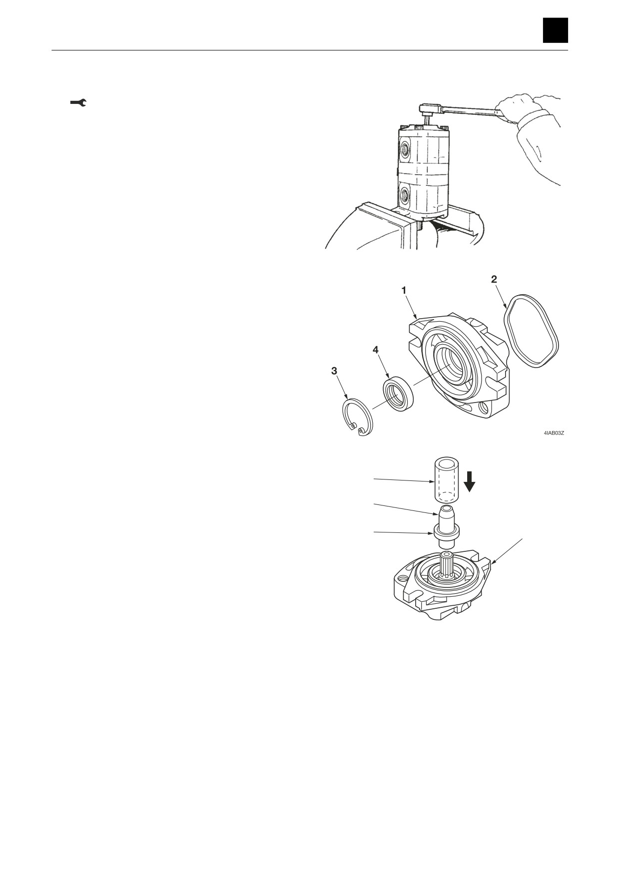
1. Remove the cap screws
Cap screw: 88.2 N·m to 93.1 N·m
4IAB02Z
2. Remove the flange (1).
3. Remove the gasket (2) from the flange (1).
4. Remove the snap ring (3) and the oil seal (4) from the
flange (1).
• Be careful not to scratch or otherwise damage the
flange.
• When assembling, install the oil seal using the jigs
“A” and “B”.
B
A
4
1
4IAB04Z
3
HYDRAULIC PUMP (SUB)
4I1AS00
DISASSEMBLY AND ASSEMBLY
4
HYDRAULIC PUMP (SUB)
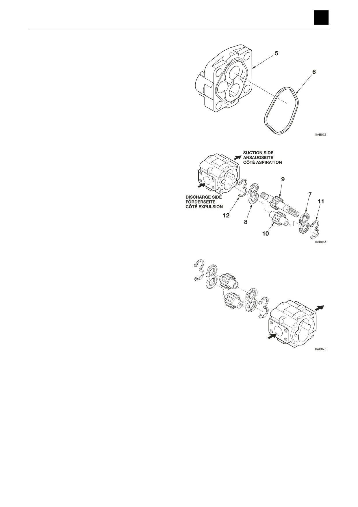
5. Remove the rear cover (5).
6. Remove the gasket (6) from the rear cover (5).
7. Disassemble the front pump.
a. Remove the bushing “A” (7), the bushing “B” (8),
the drive gear (9), and the driven gear (10) from
the housing.
• Be careful not to mix up the bushings.
• Be careful not to scratch or otherwise damage
the inner part of the housing.
8. Remove the gaskets (11) and (12) from the bushing
“A” (7) and the bushing “B” (8).
9. Disassemble the rear pump using the same proce-
dure as for the front pump.
Assembly
For assembly, refer to the construction diagram and re-
verse the disassembly procedure.
4
HYDRAULIC PUMP (SUB)
4I1AS00
DISASSEMBLY AND ASSEMBLY
4
HYDRAULIC PUMP (SUB)
Inspection and adjustment
Checking the parts
After checking the disassembled parts for dirt or discol-
oration, clean them with diesel fuel. However, do not let
diesel fuel get on rubber parts. Check each part for the
following points and if there is any trouble, repair or re-
place the part.
Housing
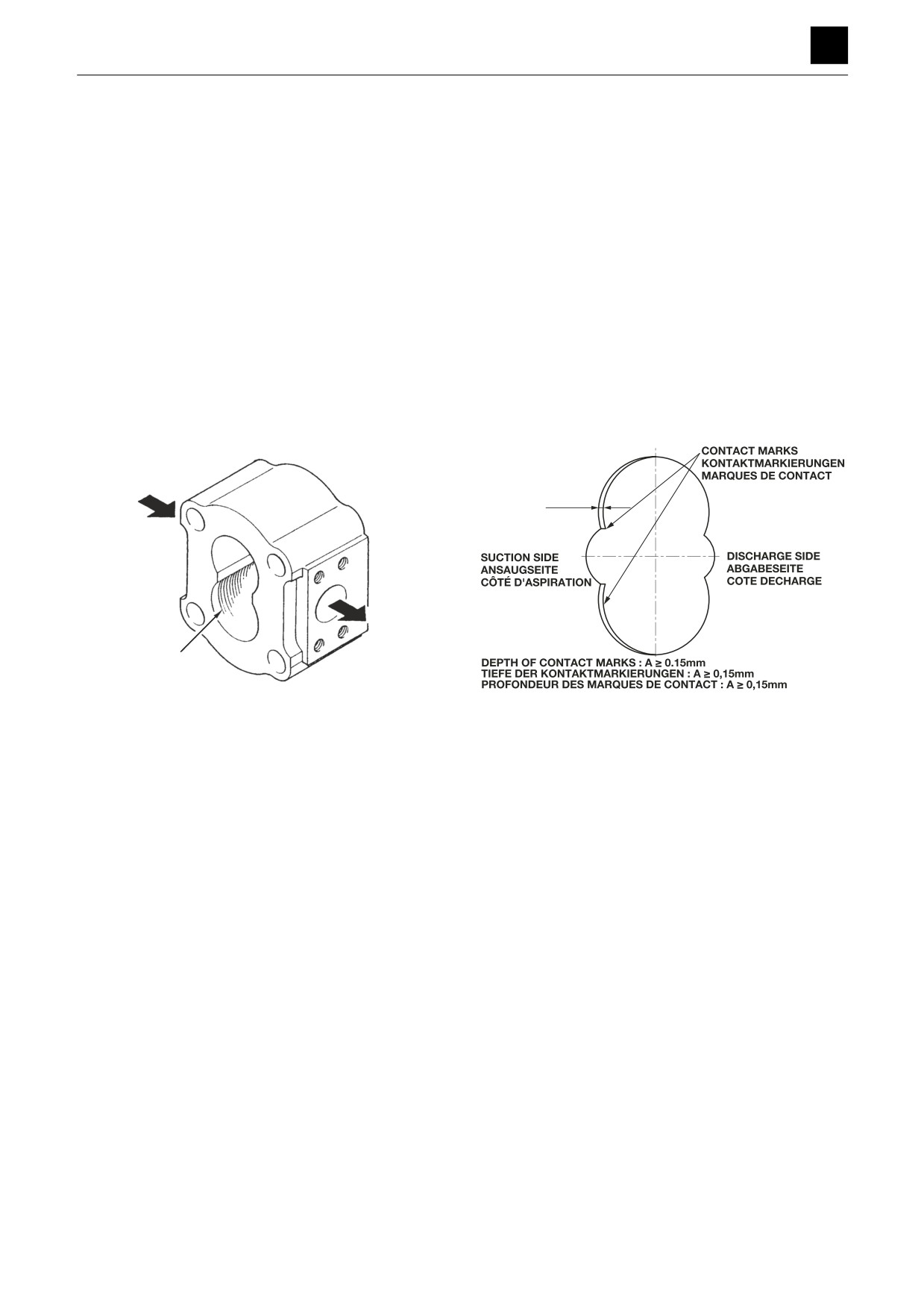
The gear pump is made so that the crests of the gear
teeth make light contact with the housing walls as a
means of increasing its efficiency. Therefore, contact
marks can be seen near the suction port in any pump that
has been operated. It is normal if the depth of the contact
marks is within 0.1 mm. If the depth exceeds the usage
limit in the above figure, replace the pump assembly.
SUCTION SIDE
ANSAUGSEITE
CÔTÉ D'ASPIRATION
A
DISCHARGE SIDE
CONTACT MARKS
ABGABESEITE
KONTAKTMARKIERUNGEN
COTE DECHARGE
MARQUES DE CONTACT
4IAB08Z
4IAB09Z
5
HYDRAULIC PUMP (SUB)
4I1AS00
DISASSEMBLY AND ASSEMBLY
4
HYDRAULIC PUMP (SUB)
Bushing
The ideal situation is for the sliding surfaces to have no
roughness and for the suction side half to be lustrous. Al-
so, it is satisfactory if strong contact marks can be seen
on the side surface on the suction side and minute con-
tact marks can be seen on the discharge side.
Replace the bushing if it is in the following condition.
• Contact marks can be seen on the sliding surface of
the entire bearing inner diameter and it is rough with
scratches that easily catch a fingernail.
• There are many scratches around the circumference
of the side surface and it is rough with scratches that
easily catch a fingernail.
• There are marks due to trapping of foreign matter on
the sliding surface of the bearing inner diameter and
the side surface.
Dirty hydraulic oil is one likely cause of such wear. In
such a case, replace the hydraulic oil and flush out the
affected hydraulic circuit completely.
Other likely causes are as follows.
• There is excessive load caused by damage to the re-
lief valve.
• There is cavitation or aeration.
• The hydraulic oil temperature is too high.
• The hydraulic oil is deteriorated.
• The viscosity of the hydraulic oil is too low.
If it becomes necessary to replace the bushings, it
means that the gear shaft and gear side surfaces are
also rough or worn severely, and the gears will thus also
need to be replaced at the same time as the bushings.
The dimensions for the bushing use limit are shown in the
figure on the right.
Gear
Replace any gear that is found to be in any of the below
conditions.
1. The shaft or gear side surfaces are rough with
scratches that can become easily caught on a finger-
nail.
2. There are cracks in the tooth roots or extremely ab-
normal wear to the tooth surfaces.
The shaft size for the gear use limit is shown in the figure
above.
6
HYDRAULIC PUMP (SUB)
4I1AS00
DISASSEMBLY AND ASSEMBLY
4
HYDRAULIC PUMP (SUB)
Seals
• Check oil seals for scratches in the seal surface, wear,
deformation, or deterioration of the rubber’s elasticity.
If any such problems are found, replace the faulty part.
• Replace the seals whenever the hydraulic pump is dis-
assembled.
• Check the backup ring for scaling and cutting. If any
such problems are found, replace the faulty part.
Test operation
The best method for testing pump operation is to mount
the pump under test onto a test stand. However, if it is not
possible to do so, use an actual machine in which the
pump to be tested is mounted.
If any abnormal wear is discovered during disassembly,
be sure to replace the hydraulic oil and return filter.
1. Insert a pressure gauge into the high-pressure pip-
ing near the pump.
2. Run the engine at 500 min-1 to 1000 min-1, and set
the control valve to the neutral position.
3. Run the pump for 10 minutes under the conditions
listed in 2 above, and increase the engine speed to
1500 min-1 to 2000 min-1 and then let the engine run
for another 10 minutes.
4. Next, run the pump for 5 minutes at a time for each
additional 1.96 MPa to 2.94 MPa of pressure until it
reaches the rated pressure.
After operating each circuit for about 5 minutes, replace
the return filter or clean it.
During the process of raising the pressure, pay careful
attention to the oil temperature, the pump surface tem-
perature, and the operating noise. If the oil temperature
or the pump surface temperature becomes abnormally
high, eliminate the load from the pump and let the tem-
perature drop before resuming the test.
Measuring the discharge volume
After completing the test operation, measure the dis-
charge volume.
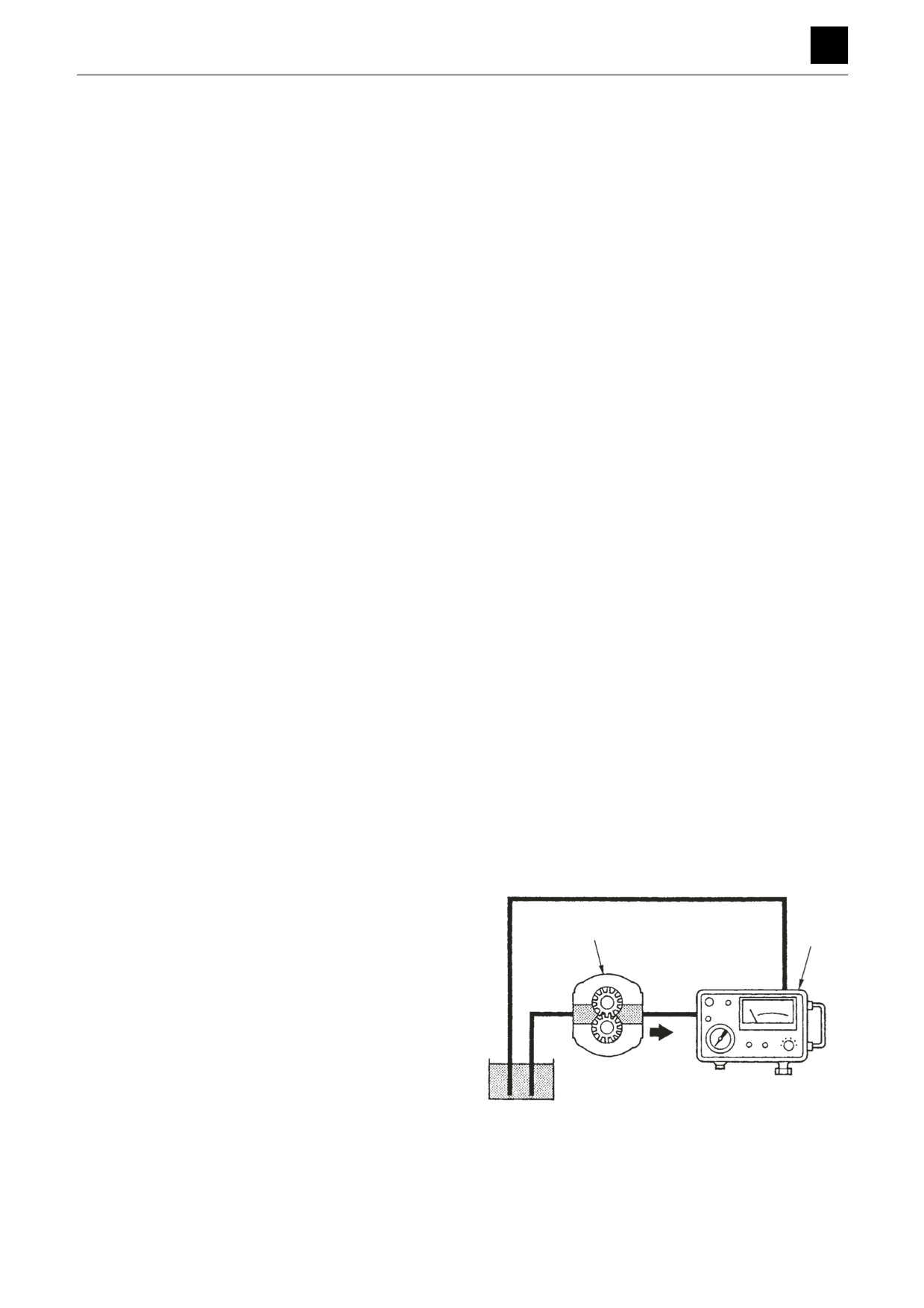
1. Connect a tester (1) to the discharge side of the
pump (2).
2
1
• Be sure to connect the tester to the proper side.
2. Open the loading valve on the tester, and start the
engine.
3. Run the engine at the rated speed.
4. Gradually close the loading valve and apply the rat-
ed pressure to the pump (2).
5. Measure the discharge volume and the pump engine
4IAB10Z
speed in rpm.
7
HYDRAULIC PUMP (SUB)
4I1AS00
DISASSEMBLY AND ASSEMBLY
4
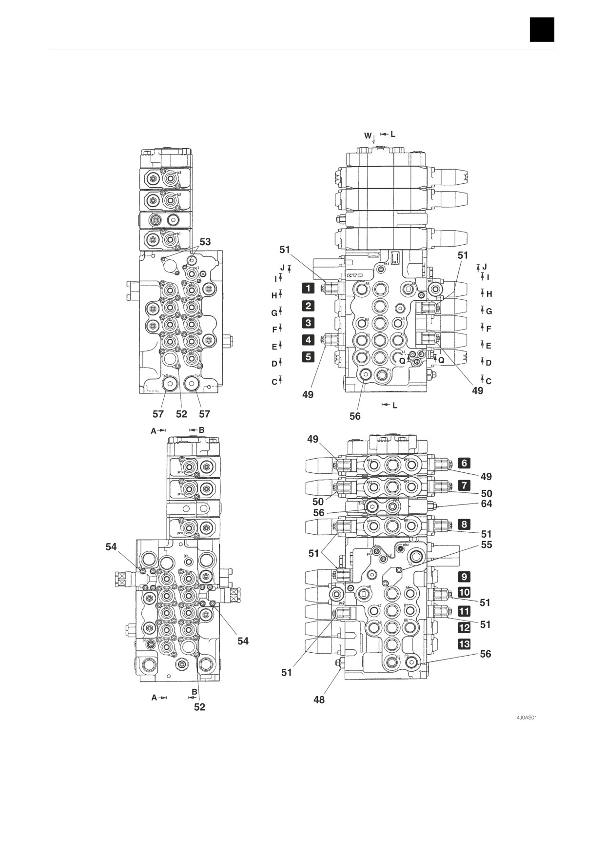
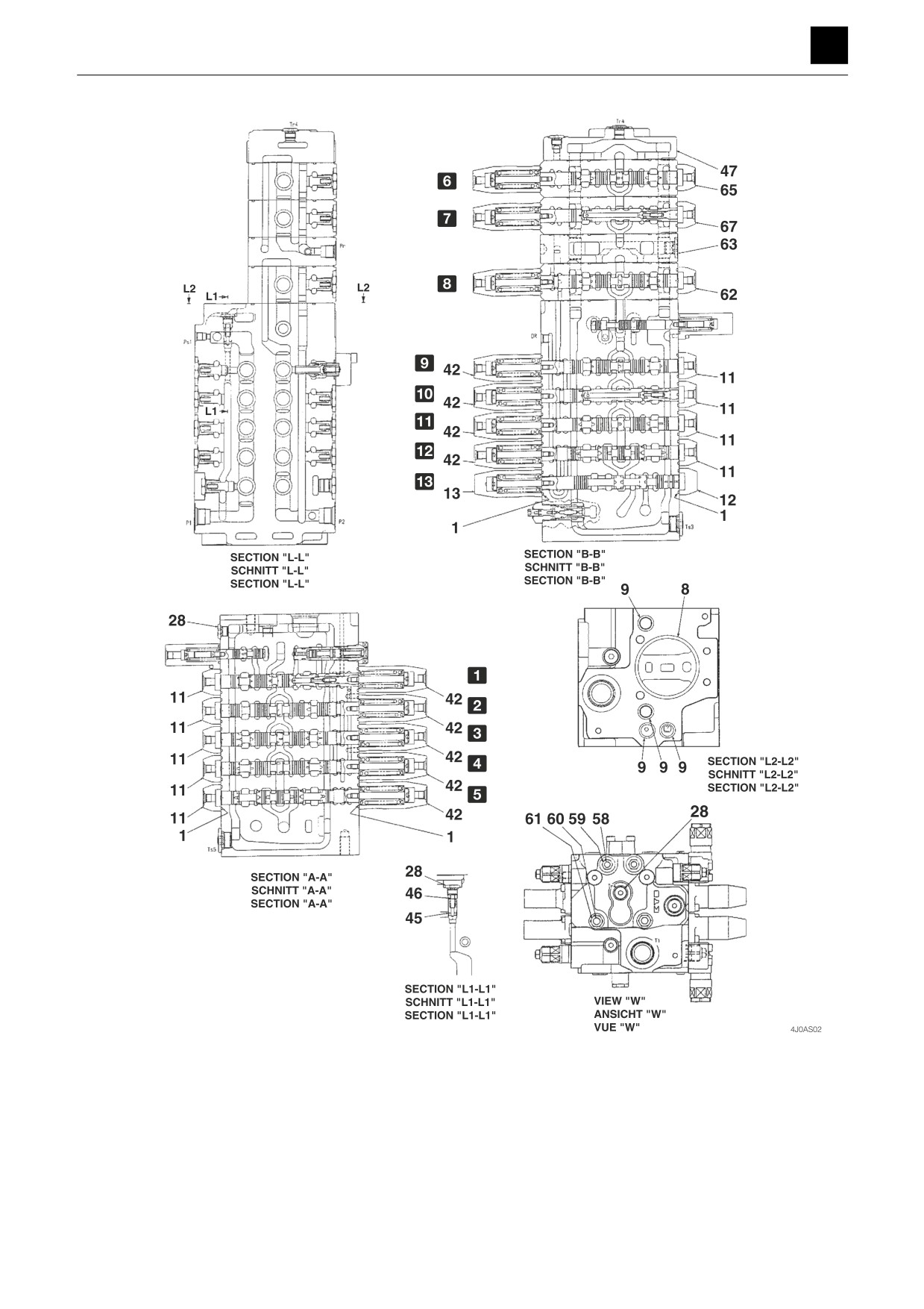
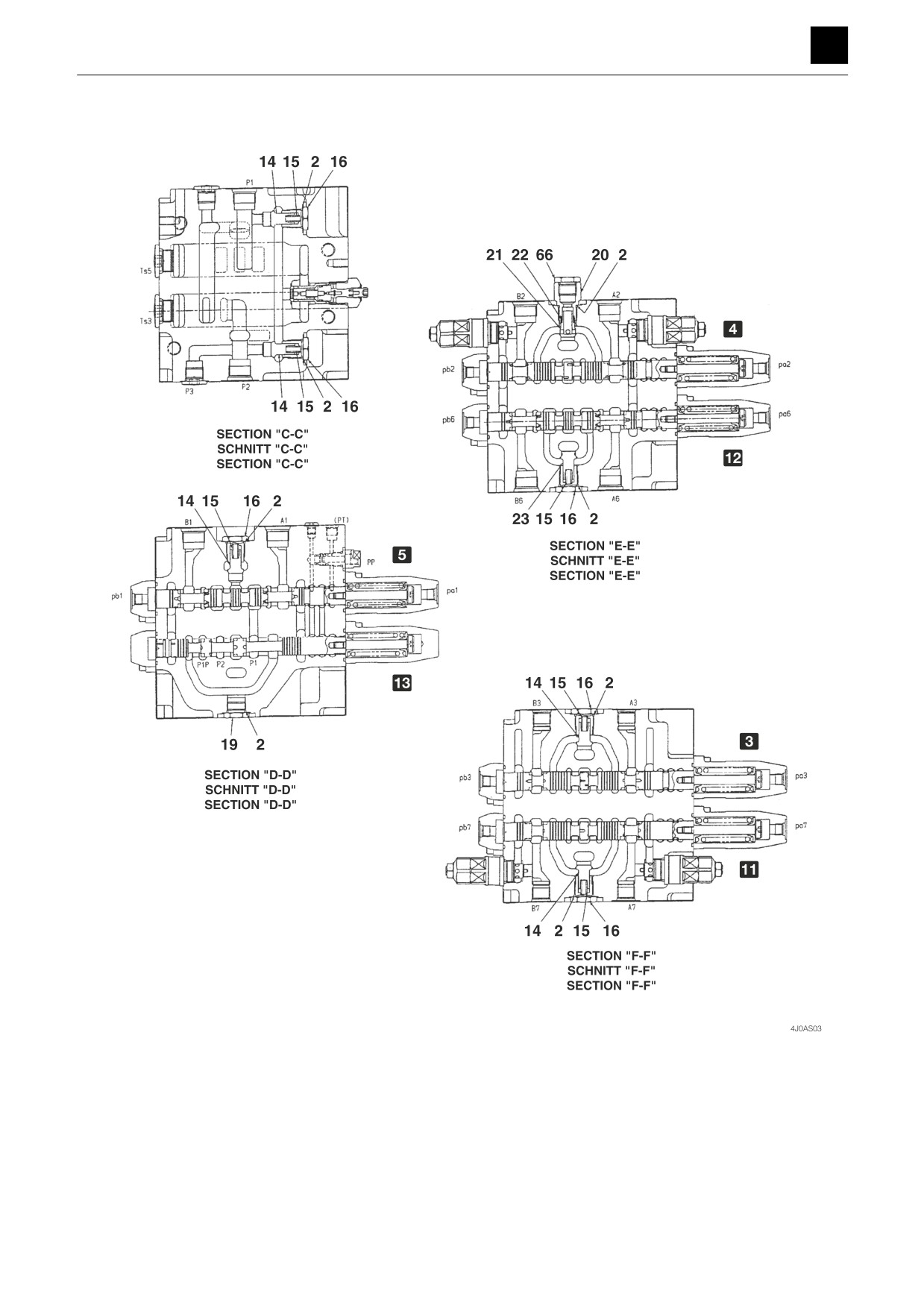
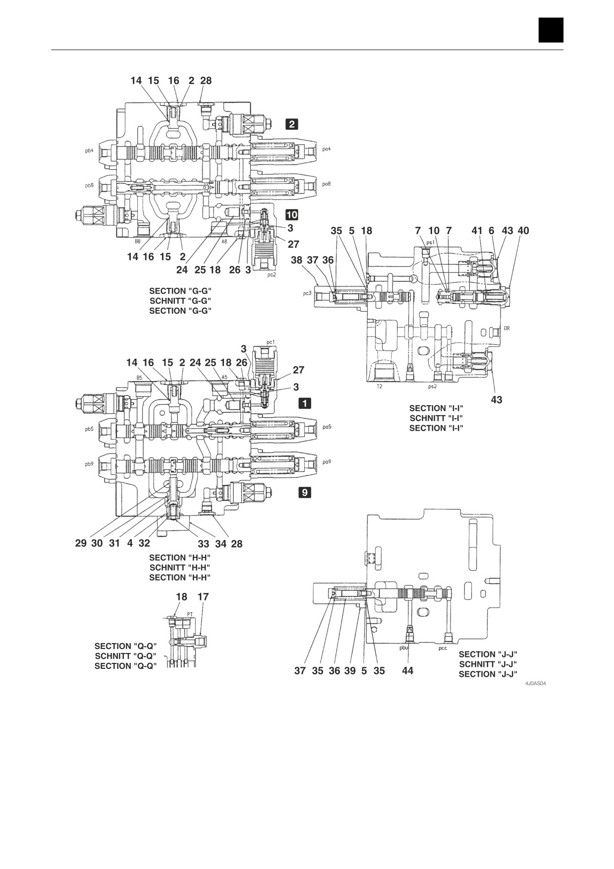
CONTROL VALVE
CONTROL VALVE
Construction
1
CONTROL VALVE
4J0AS00
DISASSEMBLY AND ASSEMBLY
4
CONTROL VALVE
2
CONTROL VALVE
4J0AS00
DISASSEMBLY AND ASSEMBLY
4
CONTROL VALVE
3
CONTROL VALVE
4J0AS00
DISASSEMBLY AND ASSEMBLY
4
CONTROL VALVE
4
CONTROL VALVE
4J0AS00
DISASSEMBLY AND ASSEMBLY
4
CONTROL VALVE
1
Arm 1
2
Boom 2
3
Slew
4
1st auxiliary line
5
Travel (R)
6
2nd auxiliary line
7
Blade
8
Swing
9
Arm 2
0
Boom 1
a Bucket
b Travel (L)
c Travel forward
1. O-ring
19. Plug
37. Spool end
53. Cap screw
2. O-ring
20. Plug
38. Cap
54. Cap screw
3. O-ring
21. Poppet
39. Cap
55. Cap screw
4. O-ring
22. Spring
40. Plug
56. Plug
5. O-ring
23. Poppet
41. Orifice
57. Plug assembly
6. O-ring
24. Poppet
42. Cap
58. Bolt
7. Backup ring
25. Spring
43. Relief valve
59. Nut
8. O-ring
26. Spacer
(Negative control)
60. Bolt
9. O-ring
27. Anti-drift valve
44. Orifice
61. Nut
10. O-ring
28. Plug assembly
45. Poppet
62. Swing section
11. Cap
29. Sleeve
46. Spring
63. Inlet housing
12. Cap
30. Poppet
47. Outlet housing
64. Main relief valve (Pr)
13. Cap
31. Spring
48. Main relief valves
65. 2nd auxiliary line section
14. Poppet
32. Poppet
(P1, P2)
66. Plug assembly
15. Spring
33. Spring
49. Port relief valve
67. Blade section
16. Plug
34. Flange
50. Port relief valve
17. Plug assembly
35. Spring holder
51. Port relief valve
18. Plug assembly
36. Spring
52. Cap screw
5
CONTROL VALVE
4J0AS00
DISASSEMBLY AND ASSEMBLY
4
CONTROL VALVE
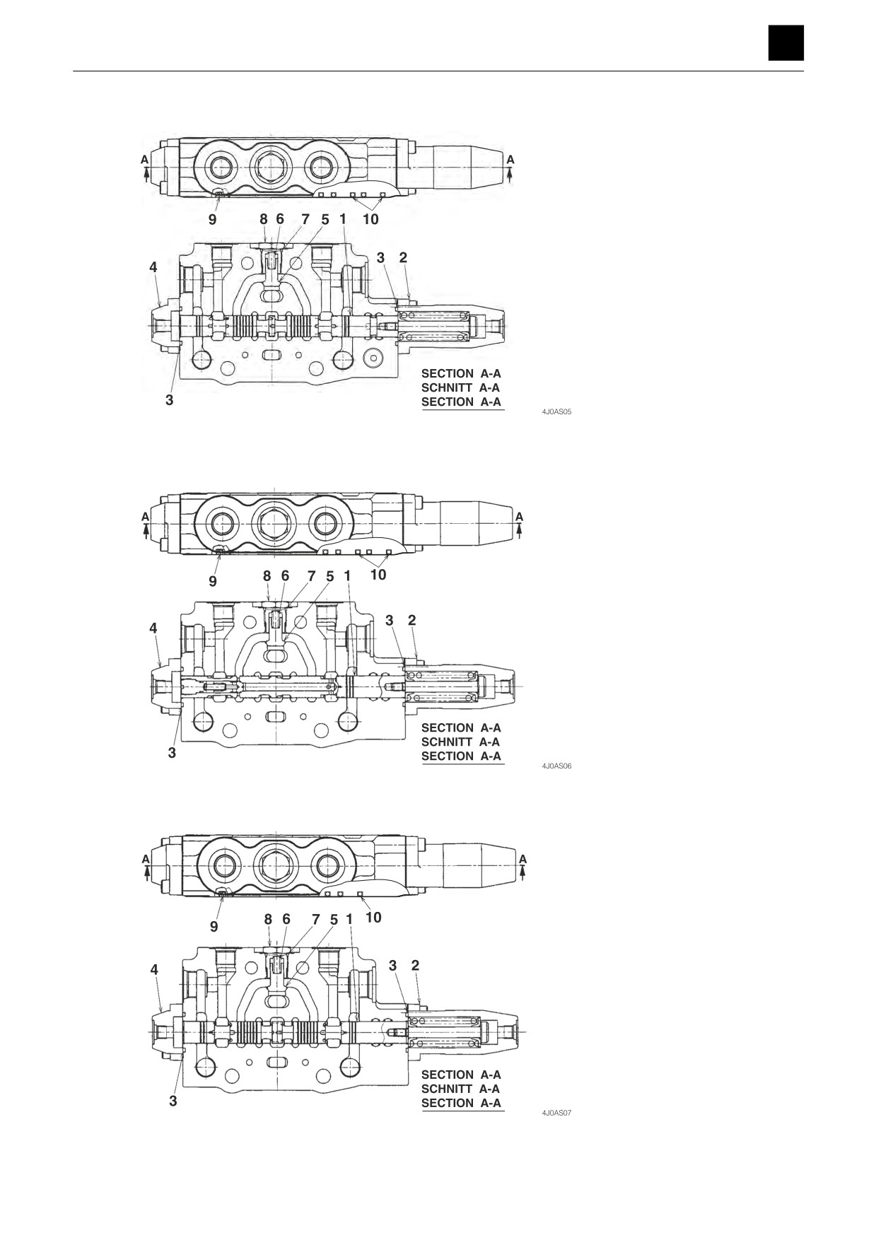
Swing section
1. Spool
2. Cap
3. O-ring
4. Cap
5. Poppet
6. Spring
7. O-ring
8. Plug
9. O-ring
10. O-ring
Blade section
1. Spool
2. Cap
3. O-ring
4. Cap
5. Poppet
6. Spring
7. O-ring
8. Plug
9. O-ring
10. O-ring
2nd auxiliary line section
1. Spool
2. Cap
3. O-ring
4. Cap
5. Poppet
6. Spring
7. O-ring
8. Plug
9. O-ring
10. O-ring
6
CONTROL VALVE
4J0AS00
DISASSEMBLY AND ASSEMBLY
4
CONTROL VALVE
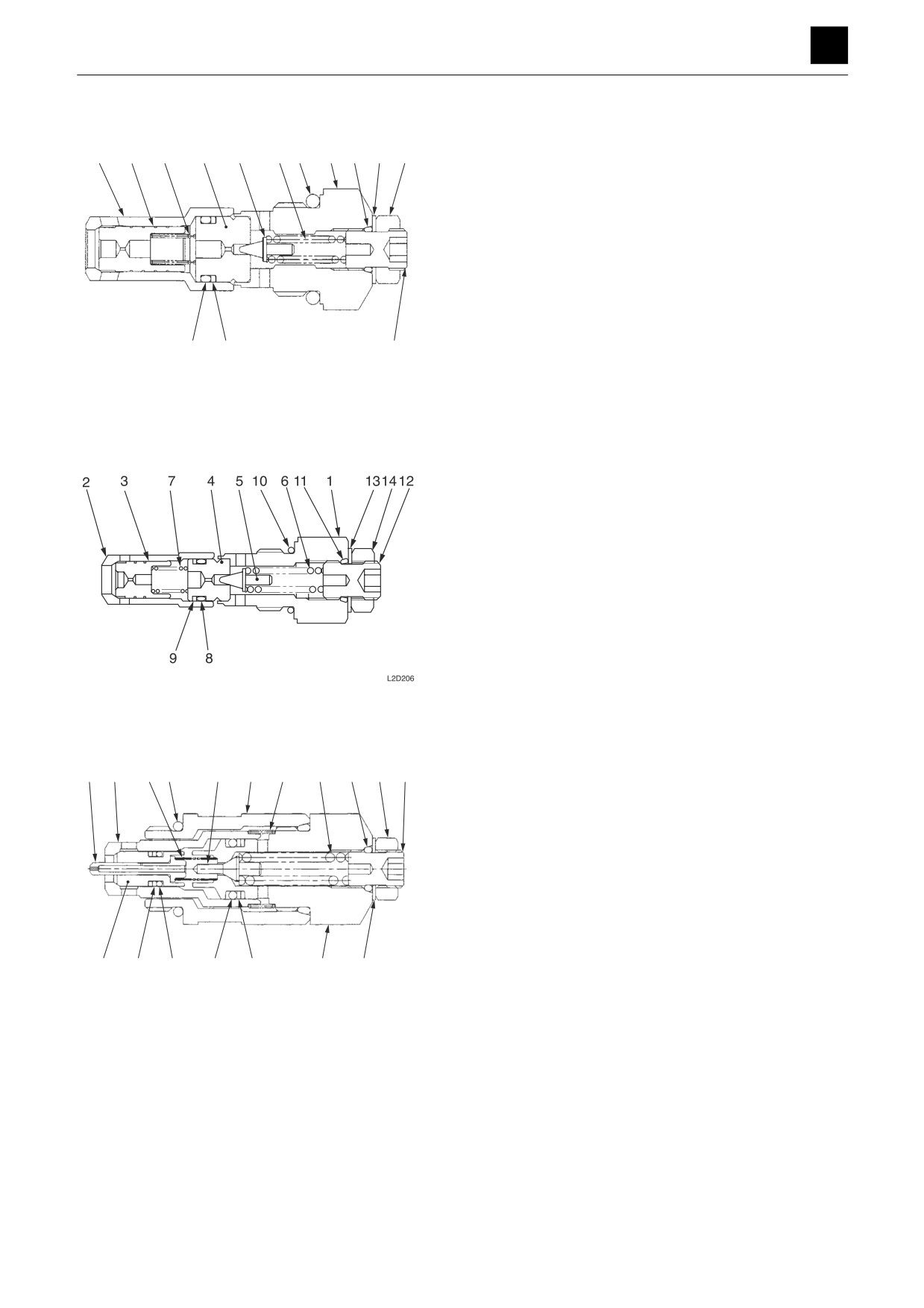
Main relief valves (P1, P2)
2
3
7
4
5
6
10
1
11 13 14
1. Plug
8. O-ring
2. Sleeve
9. Backup ring
3. Main poppet
10. O-ring
4. Piston
11. O-ring
5. Needle valve
12. Set screw
6. Spring
13. Washer
8
9
12
N0D207
7. Spring
14. Nut
Main relief valve (Pr)
1. Plug
8. O-ring
2. Sleeve
9. Backup ring
3. Main poppet
10. O-ring
4. Piston
11. O-ring
5. Needle valve
12. Set screw
6. Spring
13. Washer
7. Spring
14. Nut
Port relief valve
5
3
7
16
6
1
8
9
13 12
10
1. Housing
10. Set screw
2. Plug
11. Washer
3. Poppet
12. Nut
4. Poppet
13. O-ring
5. Piston
14. O-ring
6. Needle valve
15. Backup ring
7. Spring
16. O-ring
8. Spring
17. O-ring
4
18
17
14
15
2
11
N0D208
9. Spring
18. Backup ring
7
CONTROL VALVE
4J0AS00
DISASSEMBLY AND ASSEMBLY
4
CONTROL VALVE
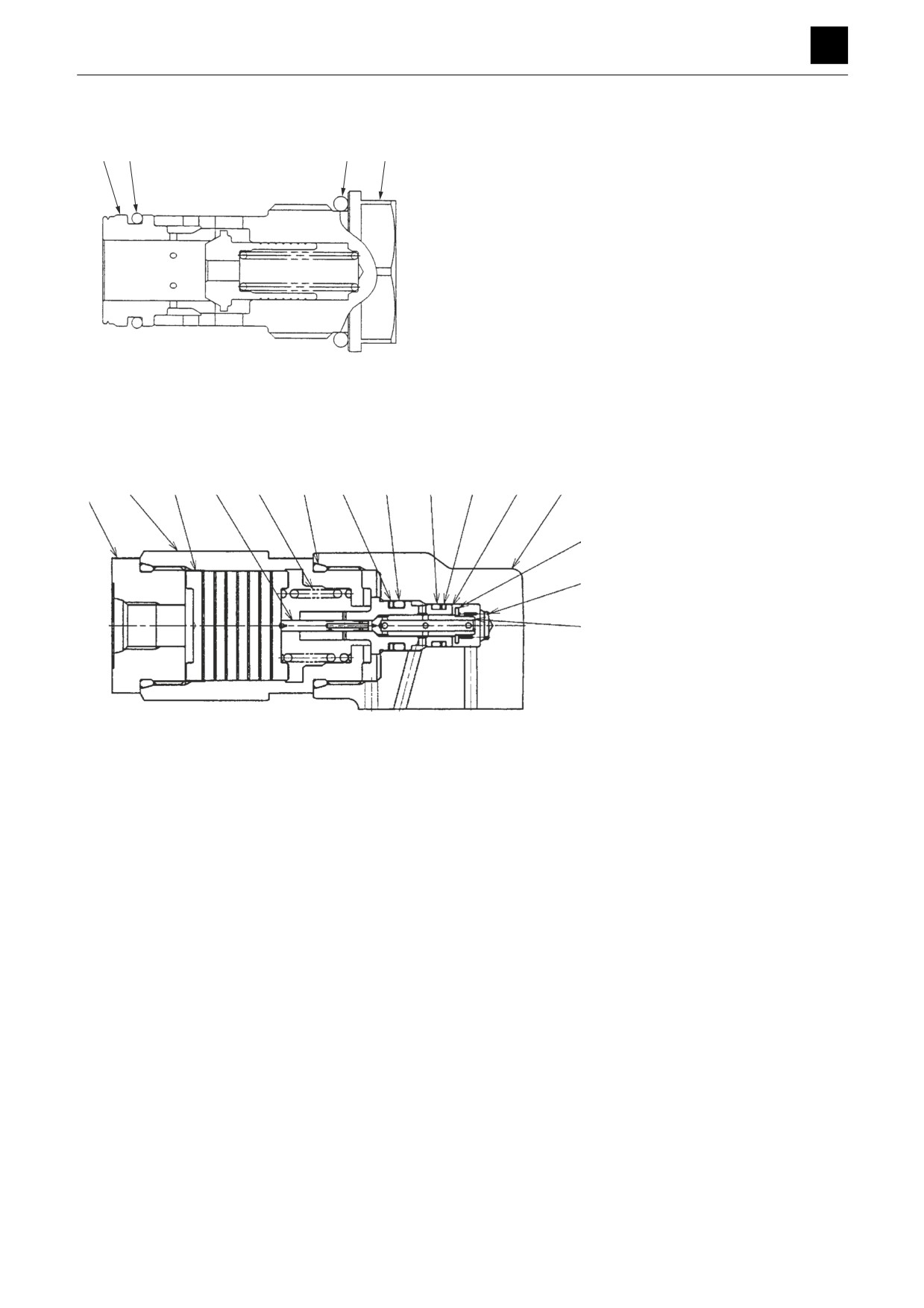
Relief valve (Negative control)
2
4
3
1
1. Plug
2. Sleeve
3. O-ring
N0D209
4. O-ring
Anti-drift valve
3
4
5
7
13
11
10
9
12
6
1
14
15
1. Body
9. O-ring
8
2. Poppet
10. O-ring
3. Plug
11. Backup ring
2
4. Piston
12. Backup ring
5. Spool
13. O-ring
6. Sleeve
14. Plug
7. Spring
15. Spring seat
8. Spring
N0D210
8
CONTROL VALVE
4J0AS00
DISASSEMBLY AND ASSEMBLY
4
CONTROL VALVE
Disassembly and assembly
WARNING
• Be careful as the springs and spring seat may pop out
when the caps are removed.
• Oil may spurt out if caps or filters are removed or pipes
are disconnected before the pressure in the hydraulic
system is released.
The numbers in parentheses, (), listed after the names of
parts throughout this document do not necessarily match
the numbers of the same parts listed in the construction
diagrams and parts lists. The numbers listed are for part
numbers used in illustrations.
General precautions
•
Perform disassembly and assembly work in a clean
place. Provide clean containers to hold parts during
disassembly.
•
Clean around the ports before disassembly. Remove
paint around connectors with a wire brush.
•
Clean the disassembled parts with wash oil.
•
Put alignment marks on all parts to ensure that they are
reassembled in the same positions.
•
After each disassembly, replace all seals and apply a
thin layer of grease to each.
•
Check each part for abnormal wear or seizing. Re-
move any burrs with sandpaper.
•
Remove adhesive from screw holes that use adhesive
through the tap. Do not reuse mounting bolts or
screws.
•
Do not use cloth gloves during assembly. Fibers from
the gloves could fall off and clog valves, etc., which
could cause parts to become faulty.
•
During assembly, be sure to apply clean hydraulic oil
to all moving parts in and sliding parts that come into
contact with the hydraulic motor and valve parts be-
fore installing or attaching the part.
•
Plug all ports once assembly has been completed in
order to prevent dust and dirt from entering.
•
Do not attempt to adjust the adjusting screws at times
other than when necessary.
9
CONTROL VALVE
4J0AS00
DISASSEMBLY AND ASSEMBLY
4
CONTROL VALVE
Disassembly
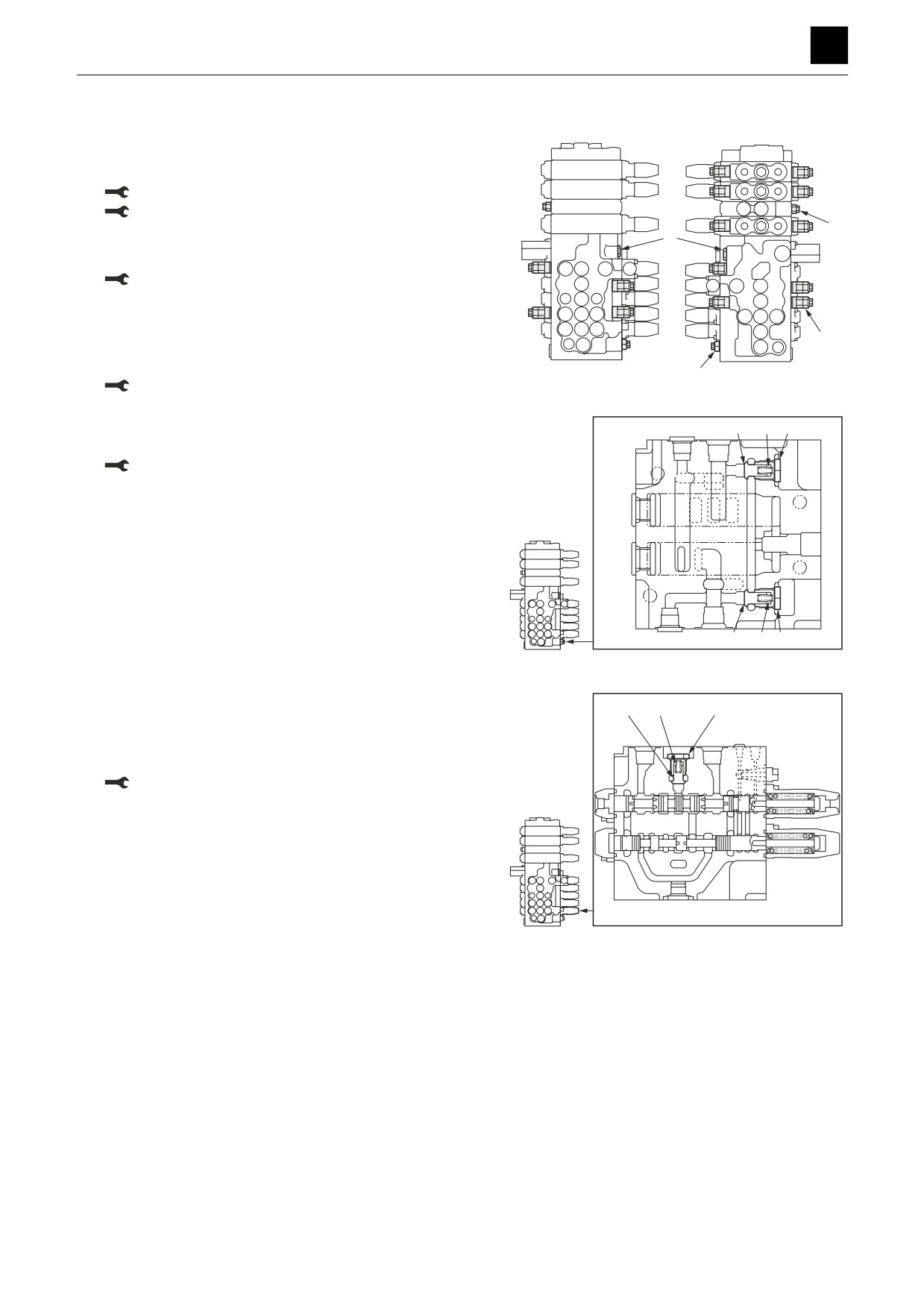
1. Remove the main relief valves P1, P2 (1) and the
main relief valve Pr (2) and then remove the O-rings
from the valves.
Valve (1): 78 N·m to 88 N·m
Valve (2): 49 N·m to 59 N·m
2
2. Remove the relief valves [Negative control] (3) and
3
then remove the O-rings from the valves.
Valve: 103 N·m to 113 N·m
3. Remove the port relief valves (4) and then remove
the O-rings from the valves.
4
• Do not disassemble the relief valves unless abso-
lutely necessary.
N0D230
1
Valve (1): 78 N·m to 88 N·m
4. Take out the plug (6), and remove the spring (7) and
8
7
6
poppet (8).
Plug: 103 N·m to 113 N·m
8
7
6
N0D231
5. Disassemble the travel section and travel forward
8
7
6
section.
a. Take out the plug (6), and remove the spring (7)
and poppet (8).
Plug: 103 N·m to 113 N·m
N0D232
10
CONTROL VALVE
4J0AS00
DISASSEMBLY AND ASSEMBLY
4
CONTROL VALVE
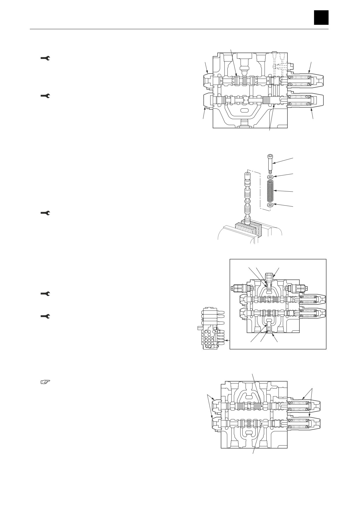
b.
Take out the cap screws, and remove the covers
11
(11) and (12).
Cap screws: 20 N·m to 25 N·m
13
9
c.
Remove the O-rings from the housing.
d.
Remove the spool assemblies (11) and (12).
e.
Take out the cap screws, and remove the covers
(13) and (14).
Cap screws: 20 N·m to 25 N·m
f.
Remove the O-rings from the housing.
14
10
12
N0D233
g.
Take out the cap screws (44), and remove the
44
spool.
• In order to keep the spool from becoming dam-
aged, secure it in place between two plates.
45
• Loctite compound has been applied to the
screw threads. Heat the screws to about 200°C
46
(392°F) to loosen the compound in order to re-
move the screws.
45
Cap screws: 9.8 N·m to 11.8 N·m
h.
Remove the spring holder (45), and take out the
spring (46) and spring holder (45).
N0D245
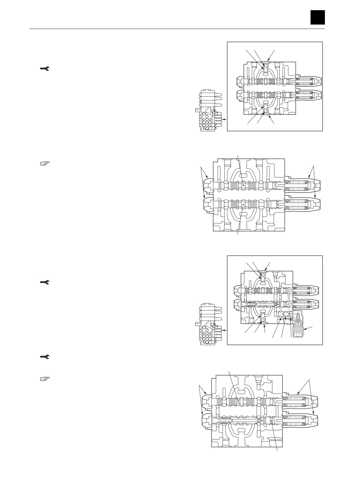
6. Disassemble the 1st auxiliary line section and travel
1716
15
section.
a. Take out the plug (15), and remove the spring (16)
and poppet (17).
Plug: 103 N·m to 113 N·m
b. Take out the plug (6), and remove the spring (7)
and poppet (18).
Plug: 103 N·m to 113 N·m
18
7
6
N0D234
c. Remove the covers (9) and (13), and take out the
19
spools (19) and (20).
“Disassembling the travel and forward travel
9
sections”
13
20
N0D235
11
CONTROL VALVE
4J0AS00
DISASSEMBLY AND ASSEMBLY
4
CONTROL VALVE
7. Disassemble the slew and bucket sections.
8
7
6
a. Take out the plug (6), and remove the spring (7)
and poppet (8).
Plug: 103 N·m to 113 N·m
8
7
6
N0D236
b. Remove the covers (9) and (13), and take out the
21
spools (21) and (22).
“Disassembling the travel and forward travel
13
9
sections”
22
N0D237
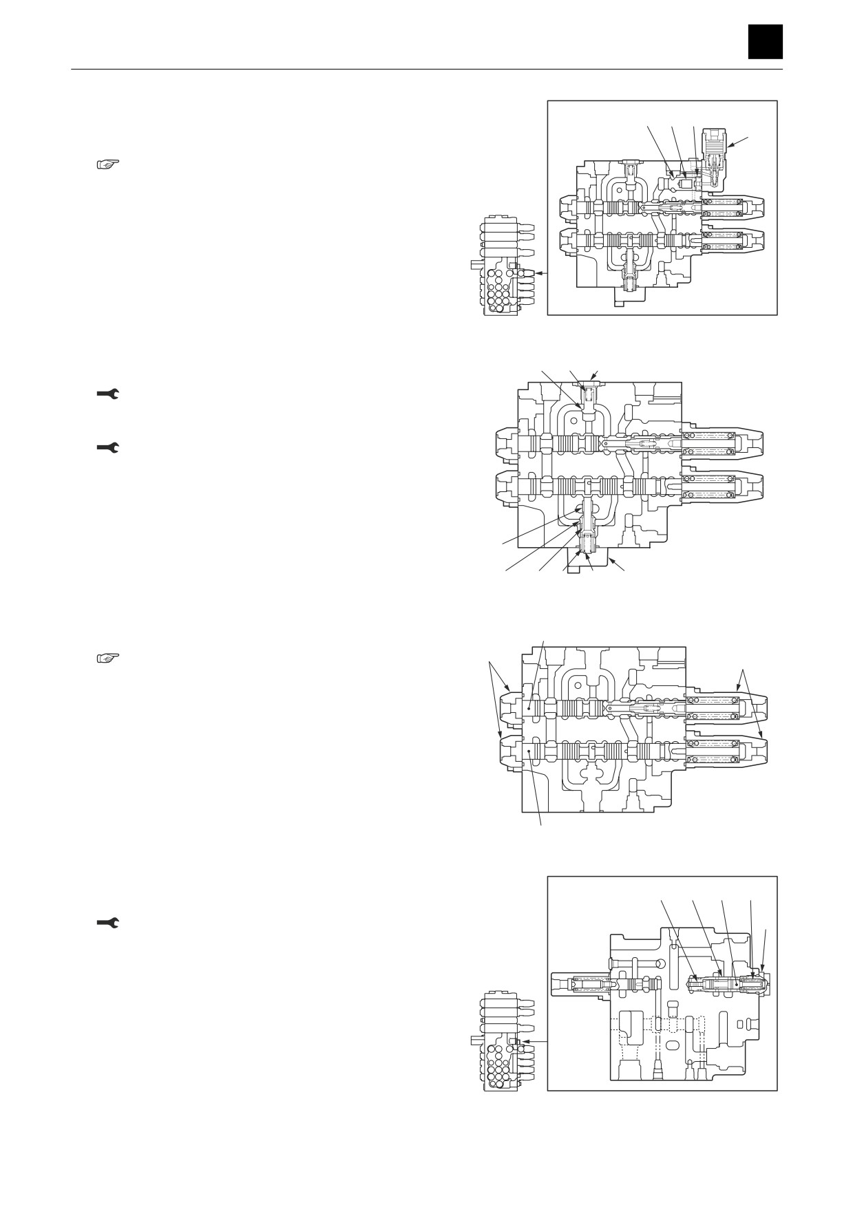
8. Disassemble the boom 1 and boom 2 sections.
8
7
6
a. Take out the cap screws, and remove the anti-drift
valve (23).
Cap screws: 20 N·m to 25 N·m
b. Take out the spacer (24), and remove the O-ring
and backup ring from the spacer (24).
• Insert a bolt (M6×1.0) into the screw hole on the
spacer and tighten it all the way down as far as
it will go and then grip the bolt with fingers and
remove it.
23
c. Remove the spring (25) and the poppet (26).
8
7
6
d. Take out the plug (6), and remove the spring (7)
2625 24
N0D238
and poppet (8).
Plug: 103 N·m to 113 N·m
e. Remove the covers (9) and (13), and take out the
27
spools (27) and (28).
9
“Disassembling the travel and forward travel
13
sections”
28
N0D239
12
CONTROL VALVE
4J0AS00
DISASSEMBLY AND ASSEMBLY
4
CONTROL VALVE
9. Disassemble the arm 1 and arm 2 sections.
26 25 24
a. Remove the anti-drift valve (23), and take out the
23
spacer (24), spring (25), and poppet (26).
“Disassembling the boom 1 and boom 2 sec-
tions”
N0D240
b. Take out the plug (6), and remove the spring (7)
8
7
6
and poppet (8).
Plug: 103 N·m to 113 N·m
c. Take out the cap screws, and remove the flange
(29).
Cap screws: 39 N·m to 44 N·m
d. Remove the O-rings from the housing.
e. Take out the sleeve (30), and remove the springs
(31) and (32).
f. Remove the poppets (33) and (34).
30
33
N0D241
32
34
31
29
g. Remove the covers (9) and (13), and take out the
35
spools (35) and (36).
13
“Disassembling the travel and forward travel
9
sections”
36
N0D242
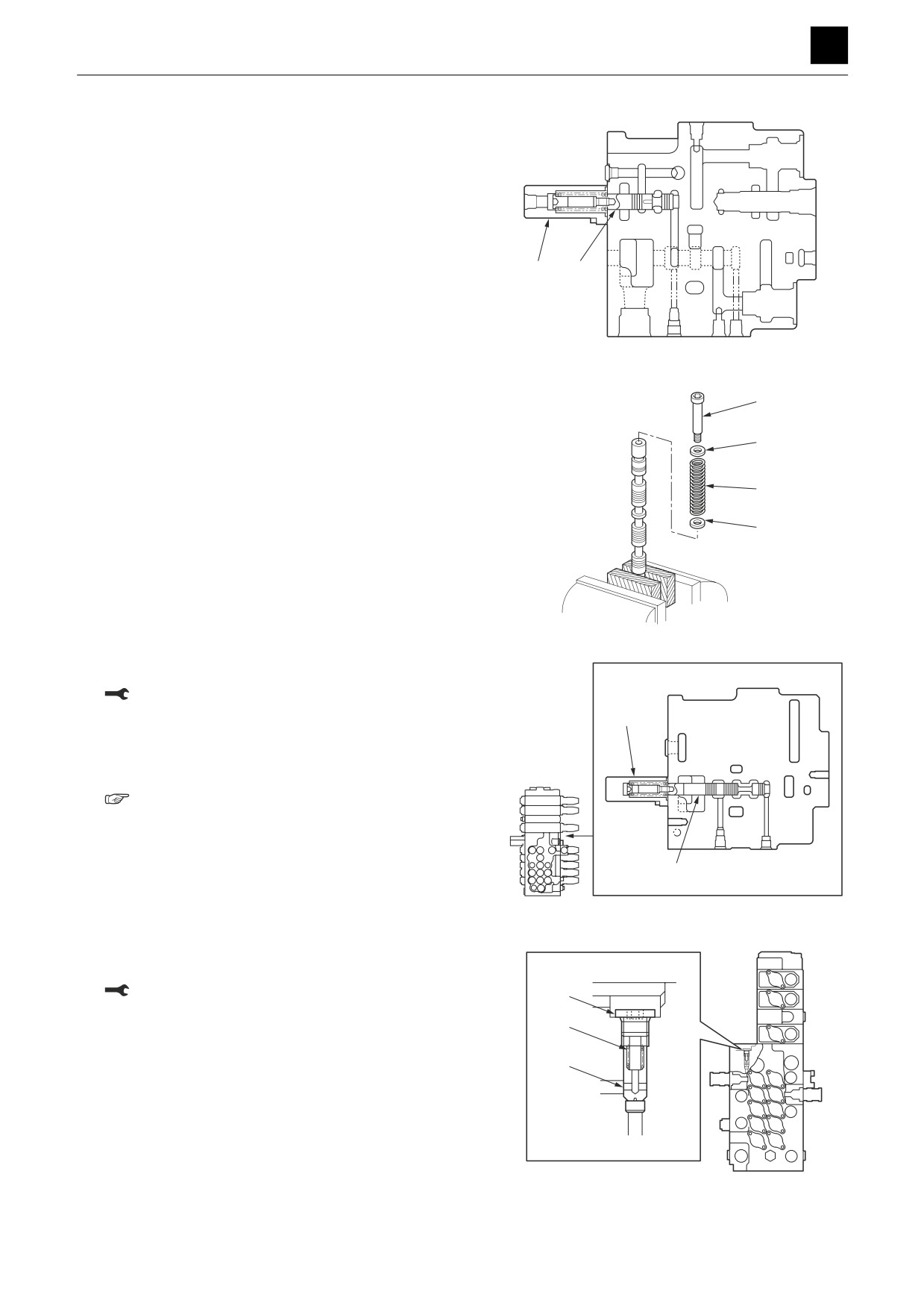
10. Take out the plug (37), and remove the O-ring from
41
40
39 38
the plug.
Plug: 103 N·m to 113 N·m
37
11. Remove the spring (38) and spool (39).
12. Remove the sleeve (40) and the piston (41).
13. Remove the O-rings and backup rings from the
sleeve (40).
N0D243
13
CONTROL VALVE
4J0AS00
DISASSEMBLY AND ASSEMBLY
4
CONTROL VALVE
14. Take out the cap screws, and remove the cover.
15. Remove the O-rings from the housing.
16. Remove the spool assembly (43).
42
43
N0D244
17. Disassemble the spool.
47
• In order to keep the spool from becoming dam-
aged, secure it in place between two plates.
48
• Loctite compound has been applied to the screw
threads. Heat the screws to about 200°C (392°F)
to loosen the compound in order to remove the
49
screws.
a. Remove the screws (47), and take out the spool.
48
b. Remove the spring holder (48), and take out the
spring (49) and spring holder (48).
N0D246
18. Take out the cap screws, and remove the cover (20).
Cap screws: 8.8 N·m to 10.8 N·m
19. Remove the O-rings from the housing.
50
20. Remove the spool assembly (51).
21. Disassemble the spool.
“17. Disassemble the spool.”
51
N0D247
22. Take out the plug (52), and remove the spring (53)
and poppet (54).
Plug: 73 N·m to 79 N·m
52
53
54
N0D248
14
CONTROL VALVE
4J0AS00
DISASSEMBLY AND ASSEMBLY
4
CONTROL VALVE
Add-on sections (Swing, blade, auxiliary lines)
1. Take out the nuts (1) and (2), and remove the speci-
1
2
fied sections.
Nut (1): 145 N·m to 159 N·m
Nut (1): 89 N·m to 97 N·m
N0D249
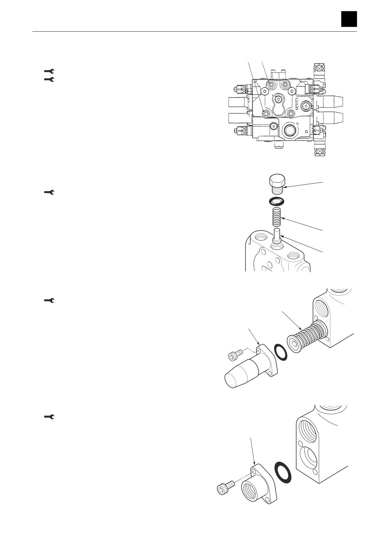
2. Take out the plug (3), and remove the spring (4) and
poppet (5).
3
Plug: 103 N·m to 113 N·m
4
5
N0D250
3. Take out the cap screws, and remove the cover (6).
Cap screws: 20 N·m to 25 N·m
7
4. Remove the O-rings from the housing.
5. Remove the spool assembly.
6
N0D251
6. Take out the cap screws, and remove the cover (8).
Cap screws: 20 N·m to 25 N·m
8
N0D252
15
CONTROL VALVE
4J0AS00
DISASSEMBLY AND ASSEMBLY
4
CONTROL VALVE
Anti-drift valve
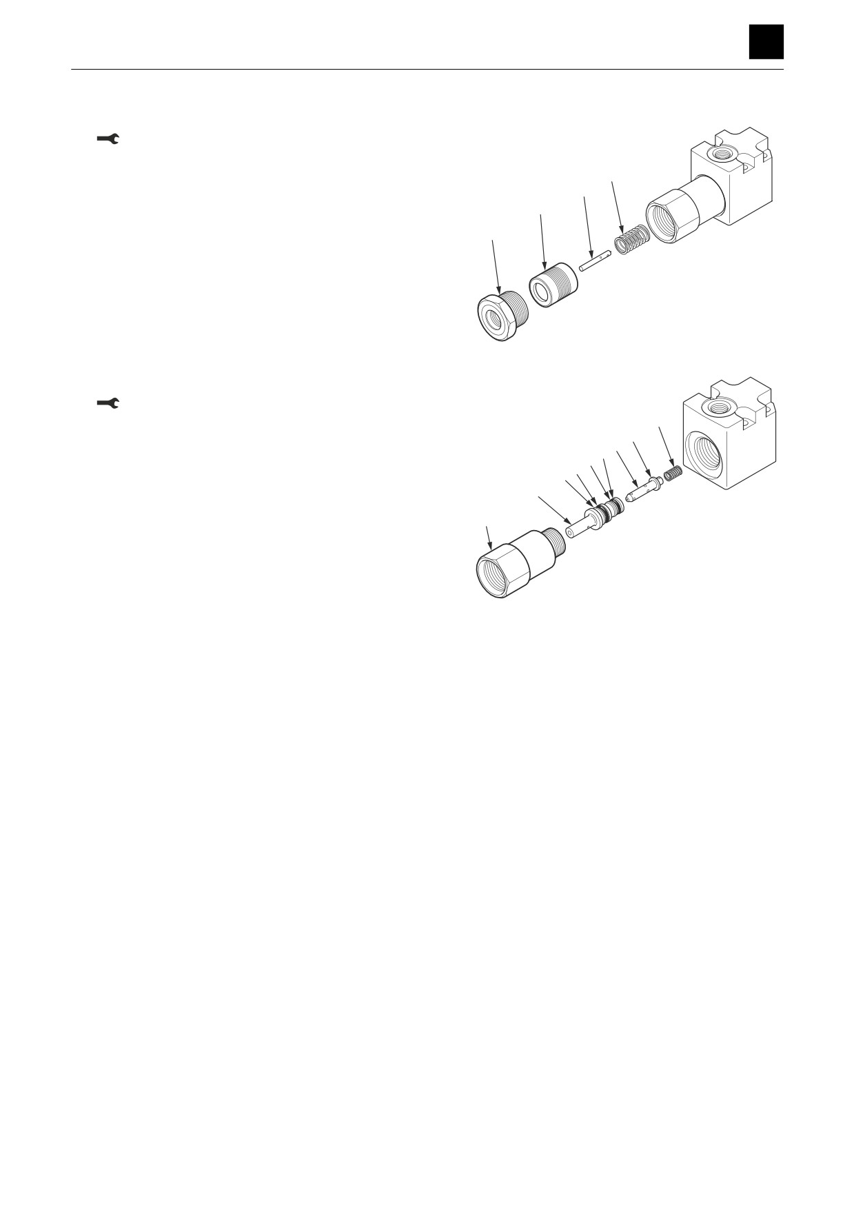
1. Take out the plug (1), and remove the O-ring.
Plug: 147 N·m to 157 N·m
2. Remove the piston (2), spool (3), and spring (4).
4
3
2
1
N0D254
3. Take out the plug, and remove the O-ring.
Plug: 147 N·m to 157 N·m
13
4. Take out the sleeve (6), and remove the O-rings (8)
12
7
and (9) and backup rings (10) and (11) from the
911
sleeve (6).
8
10
• Make sure to attach the O-rings and backup rings
6
in the proper places during assembly. Failure to
do so may cause the boom to drop.
5
5. Remove the poppet (7), spring seat (12), and spring
(13).
N0D255
16
CONTROL VALVE
4J0AS00
DISASSEMBLY AND ASSEMBLY
4
CONTROL VALVE
Main relief valves
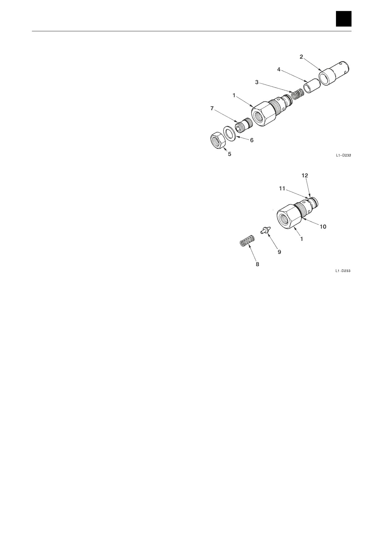
1. Remove the plug assembly (1), sleeve (2), spring (3),
and main poppet (4).
• The pilot seating is caulked to the end of the plug
and thus cannot be disassembled.
2. Take out the lock nut (5), and remove the washer (6)
and set screw (7) from the plug assembly.
• During assembly, after adjusting the set screw,
tighten the lock nut all the way down as far as it
can be.
3. Remove the spring (8) and valve (9) from the plug as-
sembly (1).
4. Remove the O-ring (10), backup ring (11), and O-
ring (12) from the plug assembly (1).
Assembly
For assembly, refer to the construction diagram and re-
verse the disassembly procedure.
17
CONTROL VALVE
4J0AS00
DISASSEMBLY AND ASSEMBLY
4
CONTROL VALVE
Inspection and adjustments
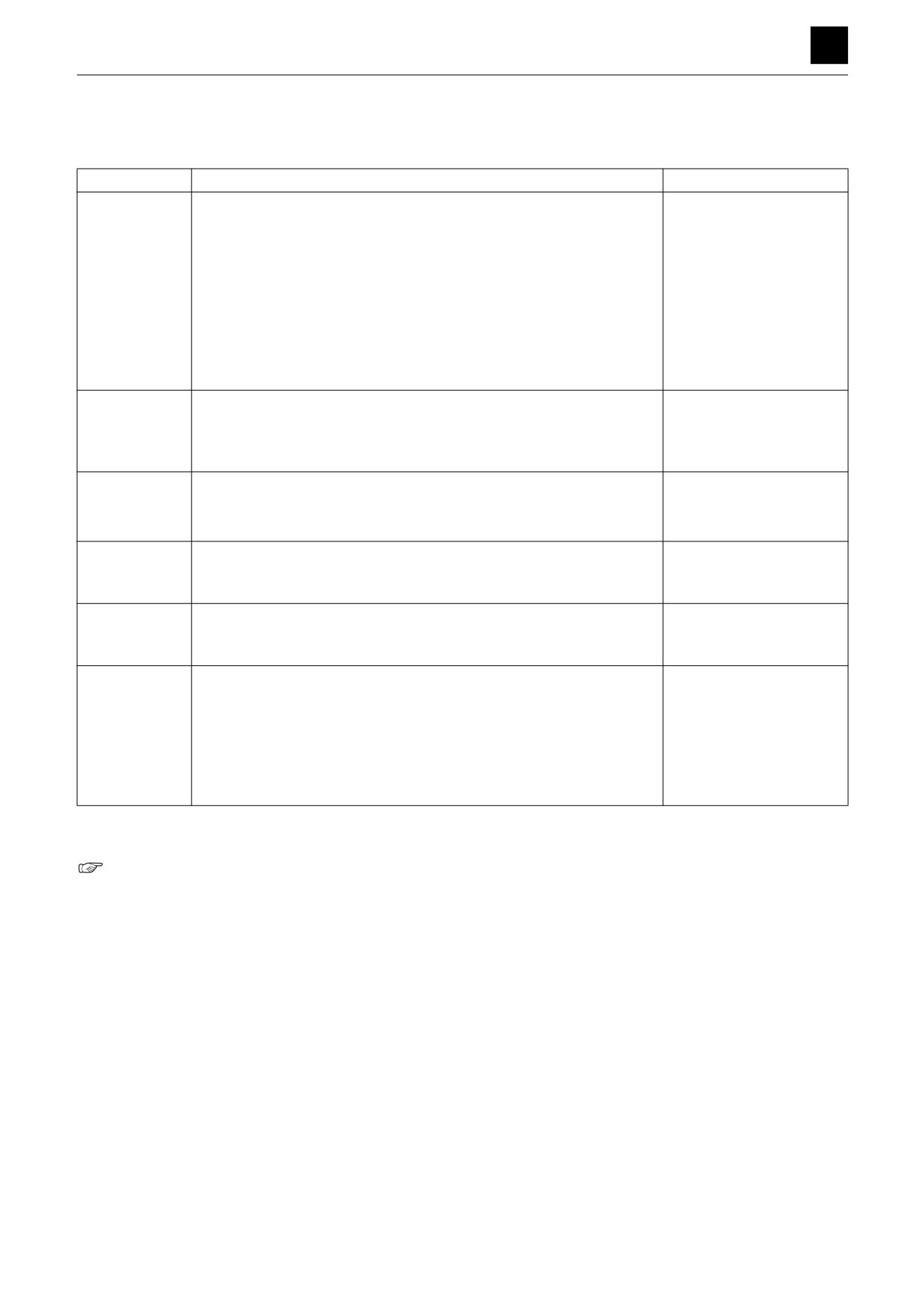
Inspection
Part
Criteria
Action
Housing,
•
If there are scratches, rust, or corrosion present on the parts that
•
Replace
Valve body
make sliding contact with the spool
•
If there are scratches, rust, or corrosion present on the seal pockets
•
Replace
of sections into which the spool enters
•
If there are scratches, rust, or corrosion of the seal part of the port in
•
Replace
contact with the O-ring
•
If there are scratches, rust, or corrosion in the seal part of the relief
•
Replace
valve, etc.
•
If there is other damage present that is thought to impair normal op-
•
Replace
eration of the machine
Spool
•
If there is scratching on the outer sliding surfaces that are rough
•
Replace
enough to be caught on a fingernail
•
If there is scratching on sliding surfaces on the end seals
•
Replace
•
If the spool does not move smoothly enough
•
Repair or replace
Load check
•
Repair or replace
•
If the sealing is faulty due to breakdown of the valve or spring
valve
•
If insertion and movement within the housing moves smoothly without
•
Normal
any parts becoming caught
Spring and re-
•
If there is noticeable rust, corrosion, deformation, or breakage of the
•
Replace
lated parts,
springs, holder, or cover
sections
Spool seals and
•
If there is leakage to external
•
Repair or replace
related parts,
•
If there is rust, corrosion, or deformation in the seal holder
•
Repair or replace
sections
Main relief
•
If there is rust or damage on the external surfaces of the parts
•
Replace
valves, port re-
•
If there is damage on surfaces that make contact with the valve
•
Replace
lief valves, anti-
seating
cavitation valve
•
If there is damage on surfaces that make contact with the poppet
•
Replace
•
If the spring is damaged or otherwise abnormal
•
Replace
•
For O-rings, backup rings, and seals
•
Replace after disassem-
bly as a general rule
Adjustment
Adjusting the main relief valve pressure
“2. Service data, Performance criteria”
18
CONTROL VALVE
4J0AS00
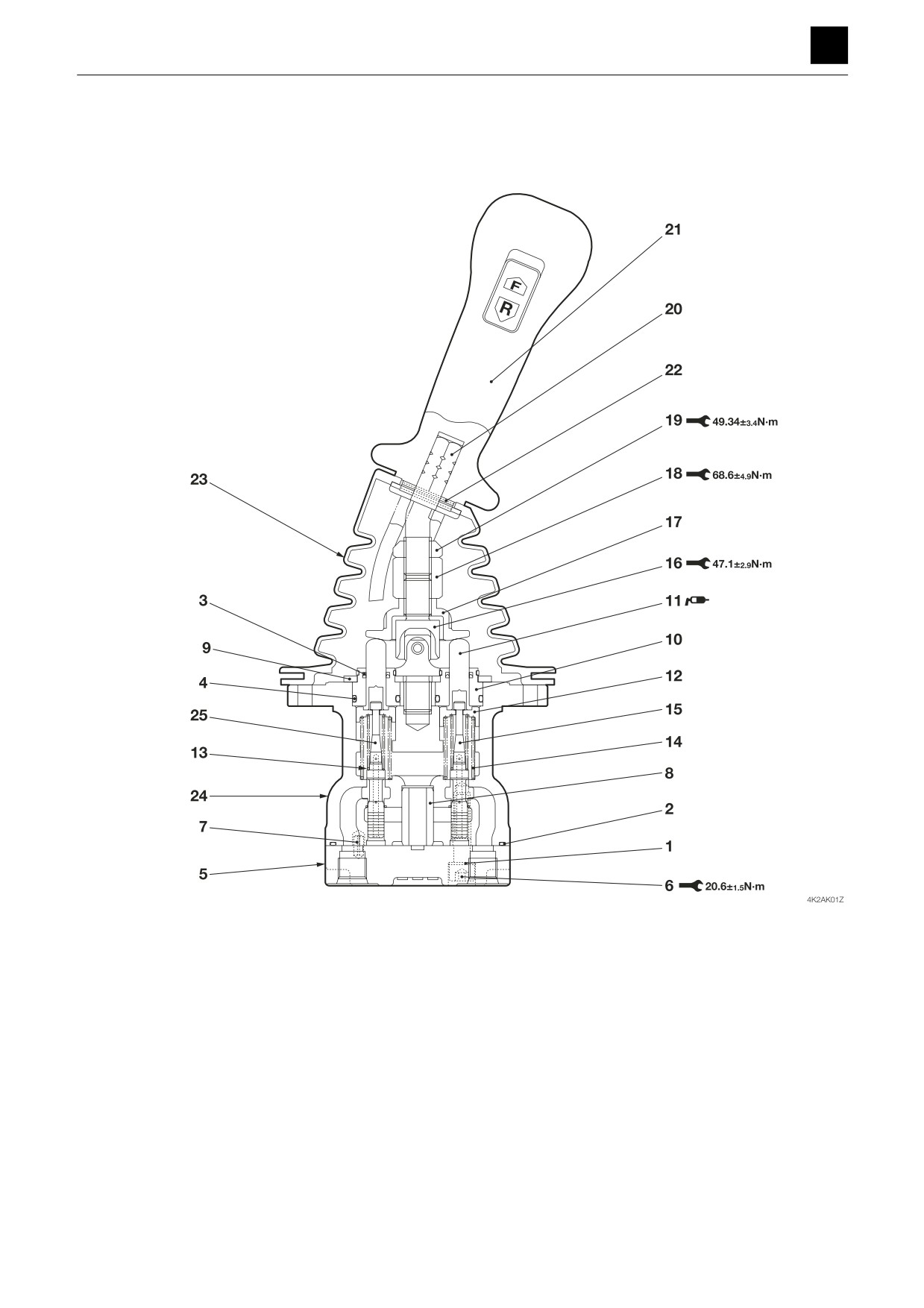
DISASSEMBLY AND ASSEMBLY
4
PILOT VALVE
PILOT VALVE
Construction
1. Washer
10. Plug
19. Nut
2. O-ring
11. Rod
20. Lever
3. Seal
12. Holder
21. Handle
4. O-ring
13. Washer
22. Spring pin
5. Plate
14. Spring
23. Boot
6. Cap screw
15. Spring
24. Casing
7. Spring pin
16. Joint
25. Spool
8. Bushing
17. Plate
9. Plate
18. Nut
1
PILOT VALVE
4K2AS00
DISASSEMBLY AND ASSEMBLY
4
PILOT VALVE
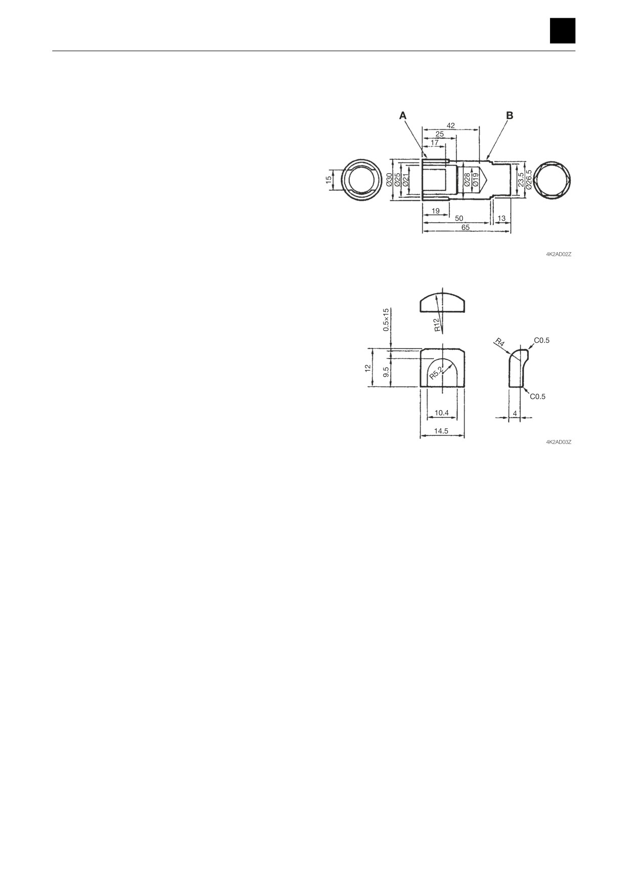
Special tools
Figures in diagrams are given in mm.
Installation jig A
Quantity: 1
Material A: S45C
Material B: SCM415N (Carburizing hardening)
Installation jig B
Quantity: 2
Material B: SCM415N (Carburizing hardening)
Disassembly and assembly
The numbers in parentheses, (), listed after the names of
parts throughout this document are used to refer to the
same parts as the numbers listed in the construction di-
agram and parts lists.
General precautions
•
Perform disassembly and assembly work in a clean
place. Provide clean containers to hold parts during
disassembly.
•
Clean around the ports before disassembly. Remove
paint around connectors with a wire brush.
•
Clean the disassembled parts with wash oil.
•
Put alignment marks on all parts to ensure that they are
reassembled in the same positions.
•
After each disassembly, replace all seals and apply a
thin layer of grease to each.
•
Check each part for abnormal wear or seizing. Re-
move any burrs with sandpaper.
•
Remove adhesive from screw holes that use adhesive
through the tap. Do not reuse mounting bolts or
screws.
•
Do not use cloth gloves during assembly. Fibers from
the gloves could fall off and clog valves, etc., which
could cause parts to become faulty.
•
During assembly, be sure to apply clean hydraulic oil
to all moving parts in and sliding parts that come into
contact with the hydraulic motor and valve parts be-
fore installing or attaching the part.
•
Plug all ports once assembly has been completed in
order to prevent dust and dirt from entering.
•
Do not attempt to adjust the adjusting screws at times
other than when necessary.
2
PILOT VALVE
4K2AS00
DISASSEMBLY AND ASSEMBLY
4
PILOT VALVE
Disassembly
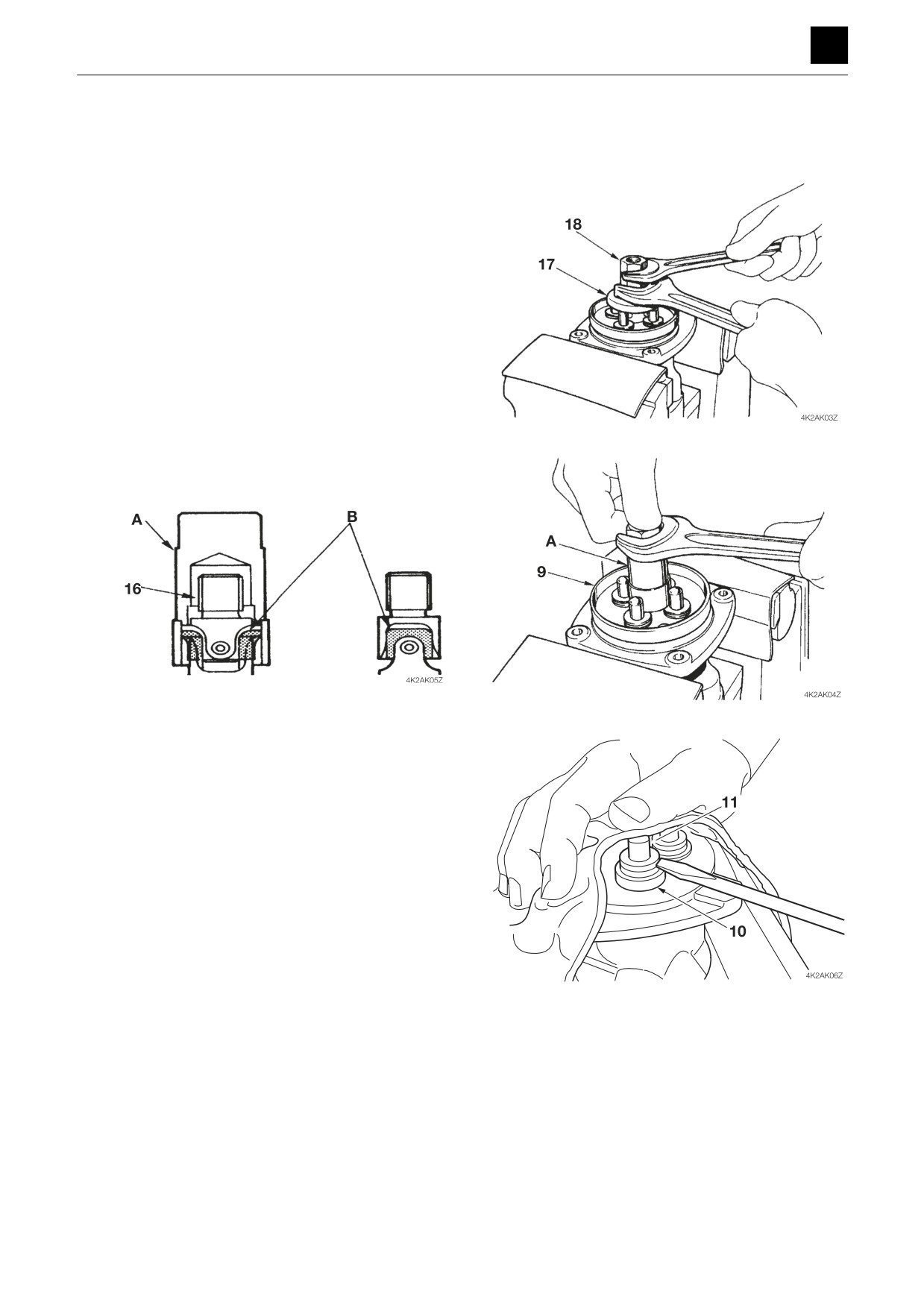
1. Disconnect the electrical wiring from the handle (21).
2. Remove the boot (23) and the handle (21).
3. Take out the nut (18), and remove the plate (17).
• Place the valve in a vice and secure it using a
copper or lead plate.
4. Take out the joint (16), and remove the plate (9).
• Use the installation jigs A and B.
• Take care as the plugs (10) may start to come out.
5. Remove the plugs (10) from the casing (24), and re-
move the rods (11) from the plugs (10).
• Use a flat-bladed screwdriver to remove the plugs
if they cannot be pried out by hand.
• Take care as the plugs may pop out due to spring
pressure.
3
PILOT VALVE
4K2AS00
DISASSEMBLY AND ASSEMBLY
4
PILOT VALVE
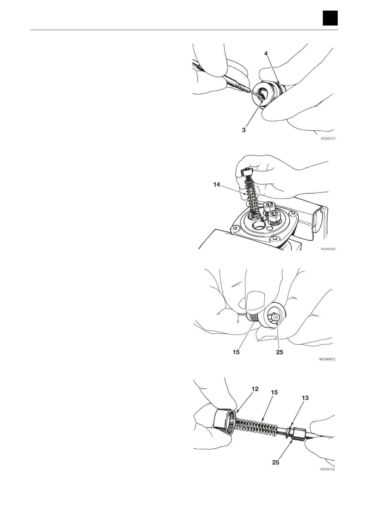
6. Remove the seals (3) and O-rings (4) from the plugs
(10).
7. Remove the reducing valves and the springs (14)
from the casing (24).
• Keep a record to indicate which hole on the cas-
ing (24) that the reducing valves came out of to
ensure that each valve can be returned to its
same hole during reassembly.
8. Disassemble the reducing valve.
a. Push in the holder (12) to compress the spring
(15) in order to move the spool (25) from the small
hole side to the large hole side of the holder (12).
• The holder is not to be pushed down by more
than 6 mm (0.24 in.).
b. Remove the holder (12), spring (15), and washer
(13) from the spool (25).
4
PILOT VALVE
4K2AS00
DISASSEMBLY AND ASSEMBLY
4
PILOT VALVE
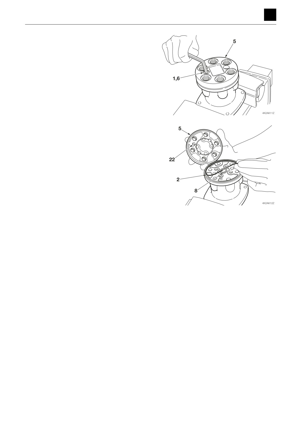
9. Take out the cap screws (6), and remove the plate
(5) from the casing (24).
• Replace any washers as they cannot be reused.
10. Remove the O-ring (2) and bushing (8) from the cas-
ing (24).
5
PILOT VALVE
4K2AS00
DISASSEMBLY AND ASSEMBLY
4
PILOT VALVE
Assembly
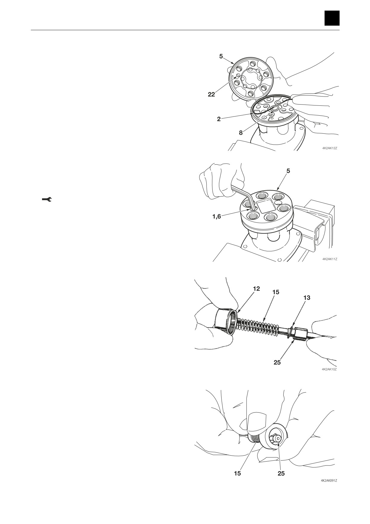
1. Attach the bushing (8) and O-ring to the casing (24).
2. Use the cap screws (6) and washers (1) to attach the
plate (5) to the casing (24).
• Make sure to replace the old washers with new
ones as they cannot be reused.
Cap screw: 20.6 N·m ± 1.5 N·m
3. Assemble the reducing valve.
a. Attach the washer (13), spring (15), and holder
(12) to the spool (25).
b. Push in the holder (12) to compress the spring
(15) in order to move the spool (25) from the large
hole side to the small hole side of the holder (12).
• The holder is not to be pushed down by more
than 6 mm (0.24 in.).
6
PILOT VALVE
4K2AS00
DISASSEMBLY AND ASSEMBLY
4
PILOT VALVE
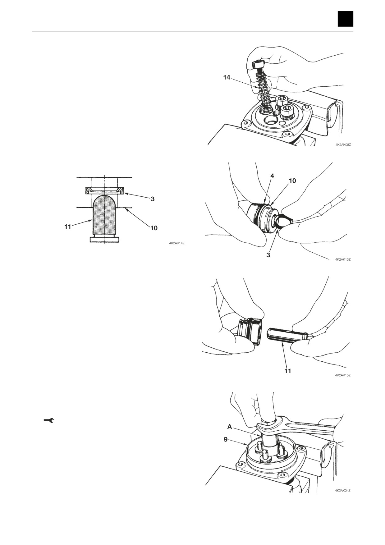
4. Insert each of the springs (16) and reducing valves
back into the same holes on the casing from which
they were removed before disassembly.
5. Attach the O-ring (4) and seal (3) to the plug (10).
6. Attach the rods (11) to the plugs (10).
• Apply lubricating oil to the rods.
7. After inserting the plugs (10) and attaching the plate
(17), attach the joint (16).
• Use the installation jigs A and B to attach the joint.
Joint: 47.1 N·m ± 2.9 N·m
7
PILOT VALVE
4K2AS00