Takeuchi Hydraulic excavator TB1140 (Serial No. 514400002~). Operator's Manual - page 9
DISASSEMBLY AND ASSEMBLY
TRAVEL MOTOR 4
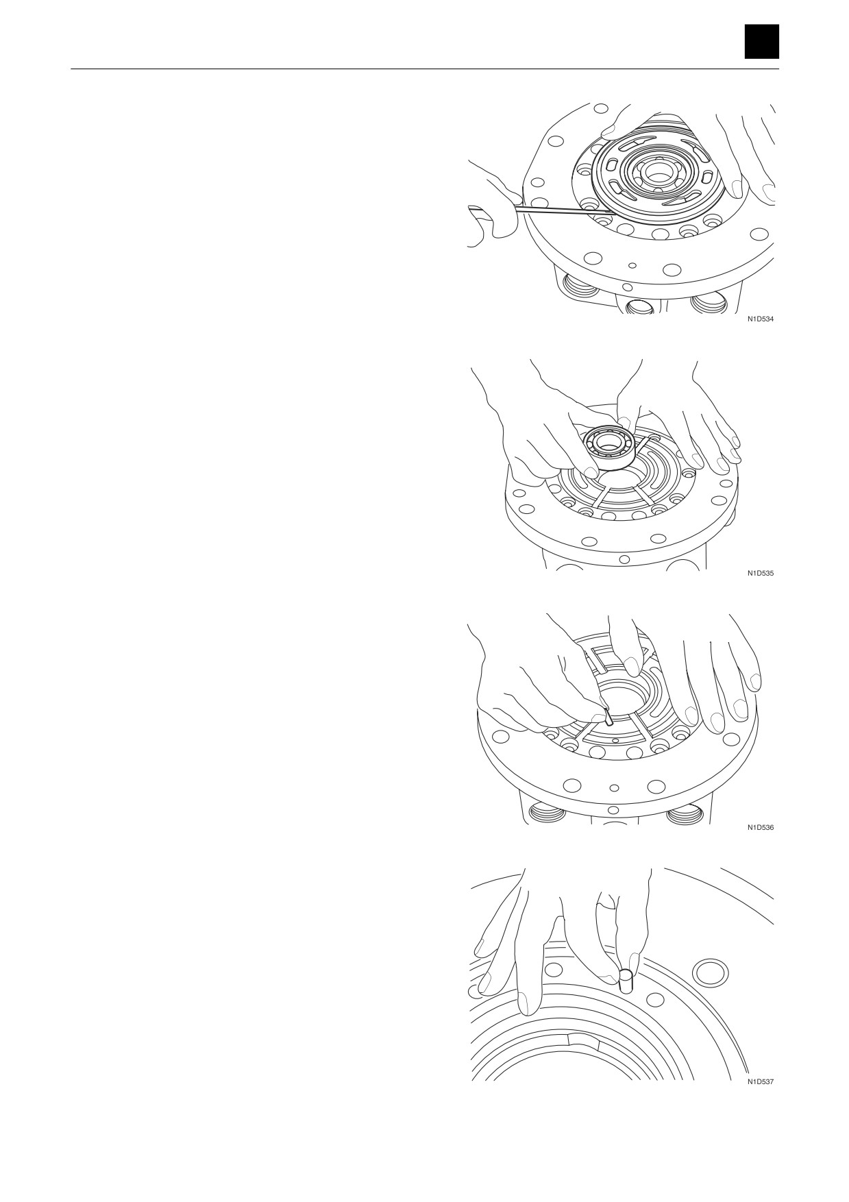
22. Remove the valve plate.
23. Remove the bearing.
24. Remove the pin from the valve body.
25. Remove the pin from the motor housing.
14
TRAVEL MOTOR
4M0AS00
DISASSEMBLY AND ASSEMBLY
TRAVEL MOTOR 4
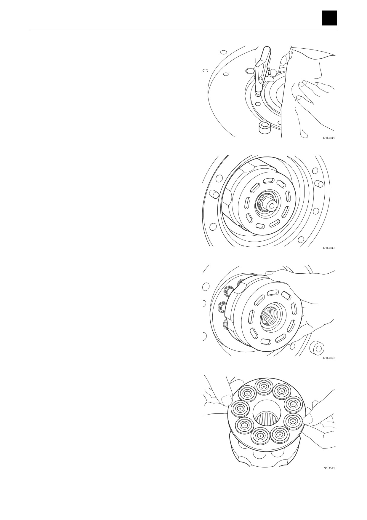
26. Remove the brake piston.
• Insert compressed air through the passage hole
on the brake piston and then remove the brake
piston.
27. Remove the four center discs and three friction
discs.
28. Remove the cylinder block.
29. Remove the piston assembly and shoe holder.
15
TRAVEL MOTOR
4M0AS00
DISASSEMBLY AND ASSEMBLY
TRAVEL MOTOR 4
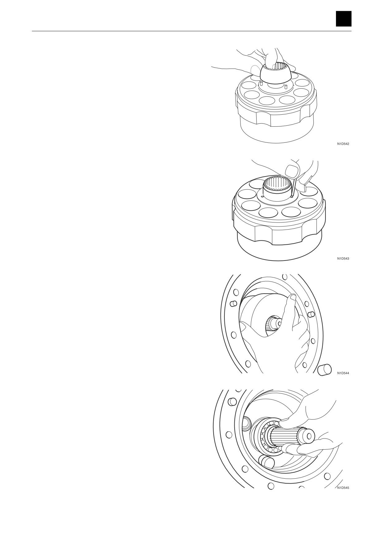
30. Remove the guide.
31. Remove the three pins.
32. Remove the swash plate.
33. Remove the shaft.
Remove the two pivots and two pins.
16
TRAVEL MOTOR
4M0AS00
DISASSEMBLY AND ASSEMBLY
TRAVEL MOTOR 4
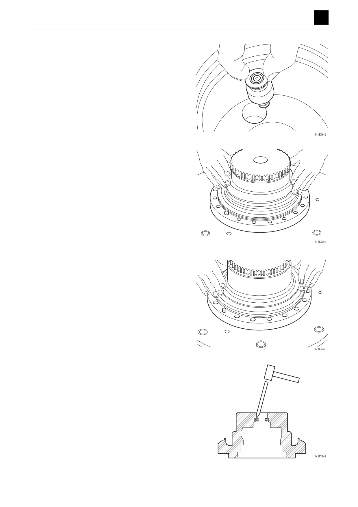
34. Remove the piston assembly and spring.
35. Remove the shim.
36. Remove the floating seal.
37. Remove the oil seal.
17
TRAVEL MOTOR
4M0AS00
DISASSEMBLY AND ASSEMBLY
TRAVEL MOTOR 4
Assembly
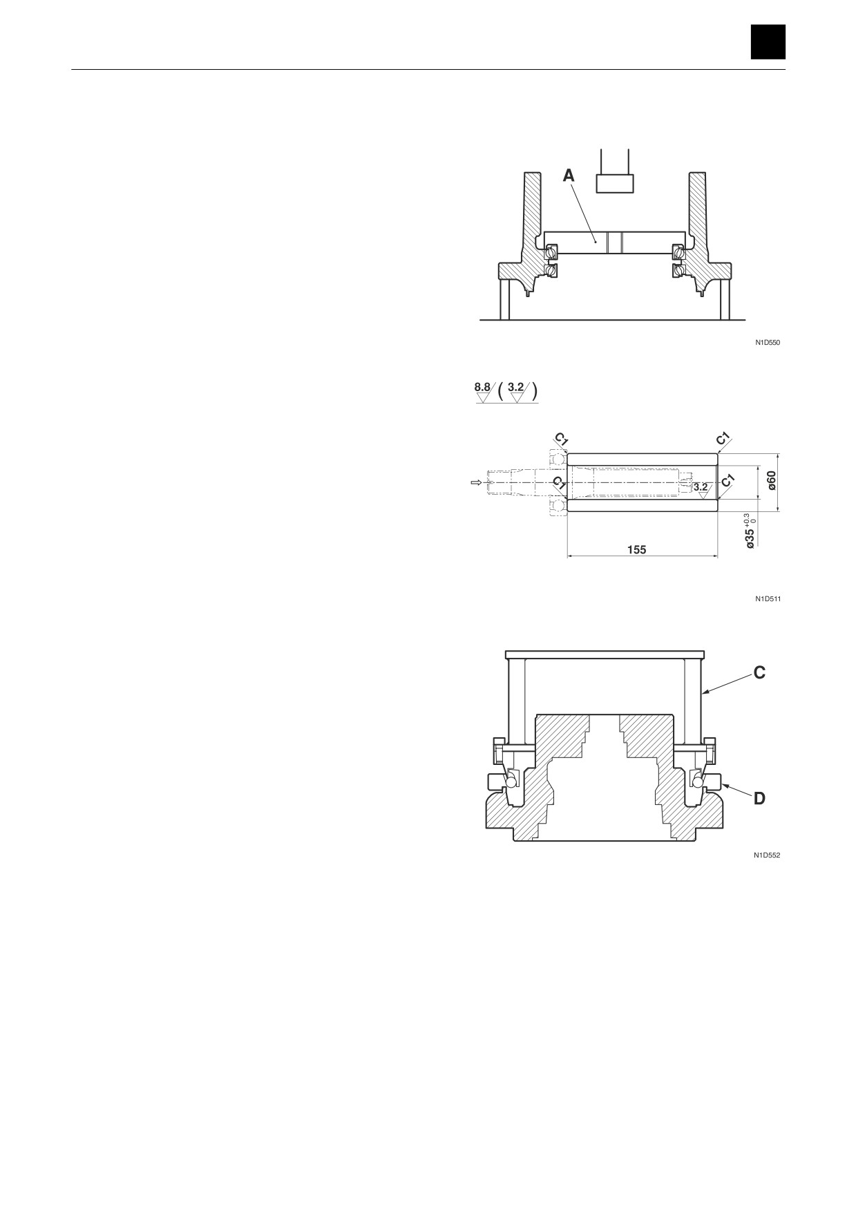
1. Press-fit the angular bearings into the gear case.
• Use the bearing press-fitting jig (A).
• Make sure to orient the bearings in the proper as-
sembly direction before completing this step.
2. Attach the floating seal to the gear case.
a. Grease the O-ring on the floating seal.
b. Place the jigs and seal in the order of inserting jig
B, floating seal, and then inserting jig C.
c. Push down on the inserting jig B until it reaches
the inserting jig C.
d. Remove the inserting jigs, and check to ensure
that the end surface of the gear case and surface
of the floating seal are parallel to each other and
separated by less than 1 mm.
3. Attach the floating seal to the motor housing.
a. Grease the O-ring on the floating seal.
b. Place the jigs and seal in the order of inserting jig
D, floating seal, and then inserting jig C.
c. Push down on the inserting jig B until it reaches
the inserting jig D.
d. Remove the inserting jigs, and check to ensure
that the end surface of the Motor housing and sur-
face of the floating seal are parallel to each other
and separated by less than 1 mm.
18
TRAVEL MOTOR
4M0AS00
DISASSEMBLY AND ASSEMBLY
TRAVEL MOTOR 4
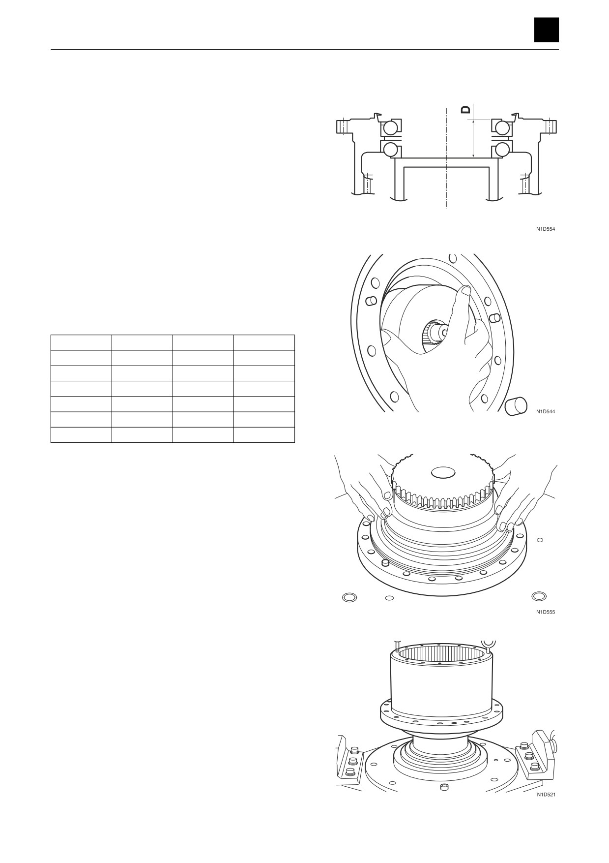
4. Perform precompression adjustment of the angular
bearing.
• Perform whenever the gear case, angular bear-
ing, or spindle is replaced. The angular bearing
may become damaged or fail in a short amount of
time if the precompression is not set appropriate-
ly.
a. Place the lock washer in the motor housing tem-
porarily, and measure the dimension C.
b. Measure the assembly thickness D of the angular
bearing.
c. Subtract dimension D from dimension C. Select a
shim that will introduce a clearance of between
0.13 mm and 0.17 mm according to the resultant
rank listed in the below table.
Code
T (mm)
Code
T (mm)
A
0.9
G
1.5
B
1.0
H
1.6
C
1.1
I
1.7
D
1.2
J
1.8
E
1.3
K
1.9
F
1.4
L
2.0
5. Attach the shim selected in step 4. above to the mo-
tor housing.
6. Attach the gear case to the motor housing.
19
TRAVEL MOTOR
4M0AS00
DISASSEMBLY AND ASSEMBLY
TRAVEL MOTOR 4
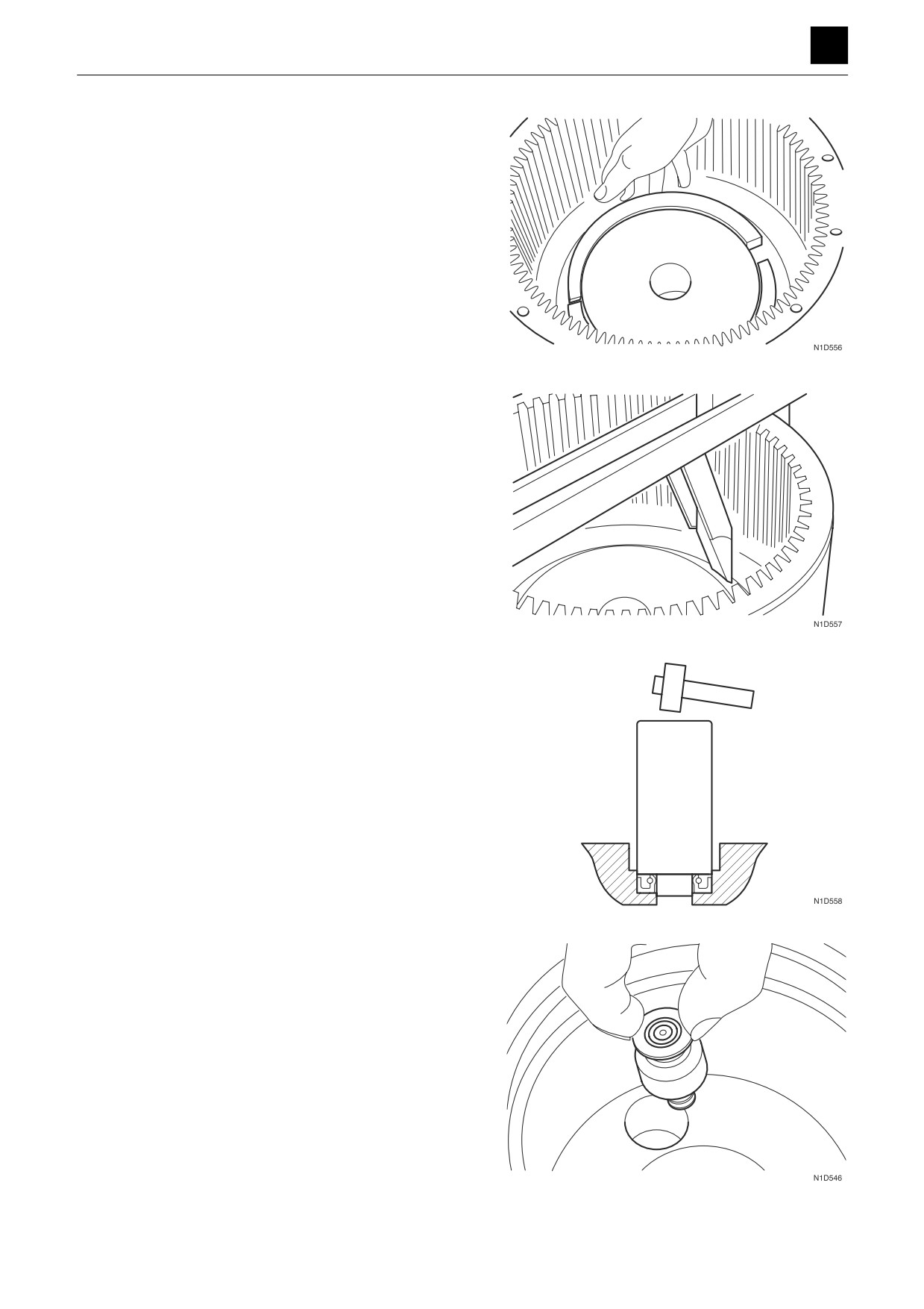
7. Line up the lock washer with the groove on the motor
housing.
8. Use the inserting jig E to attach the lock washer to the
groove on the motor housing.
9. Attach the oil seal to the motor housing.
• Use the inserting jig F.
• Apply lithium grease to the lip on the oil seal.
• Make sure to orient the oil seal in the proper as-
sembly direction before completing this step.
10. Insert the two pins into the pin holes on the motor
housing.
11. Attach the two pivots to the pins that were attached
to the motor housing.
• Apply lithium grease to one hemispherical sur-
face of each pivot.
12. Insert the spring into the piston assembly.
• Grease the spring.
13. Apply hydraulic oil to the sliding surfaces of the pis-
ton assembly and then insert the piston into the pis-
ton hole on the motor housing.
14. Attach the two pins to the motor housing.
20
TRAVEL MOTOR
4M0AS00
DISASSEMBLY AND ASSEMBLY
TRAVEL MOTOR 4
WARNING
Wear gloves when completing this procedure to keep
from getting burned on the heated bearing.
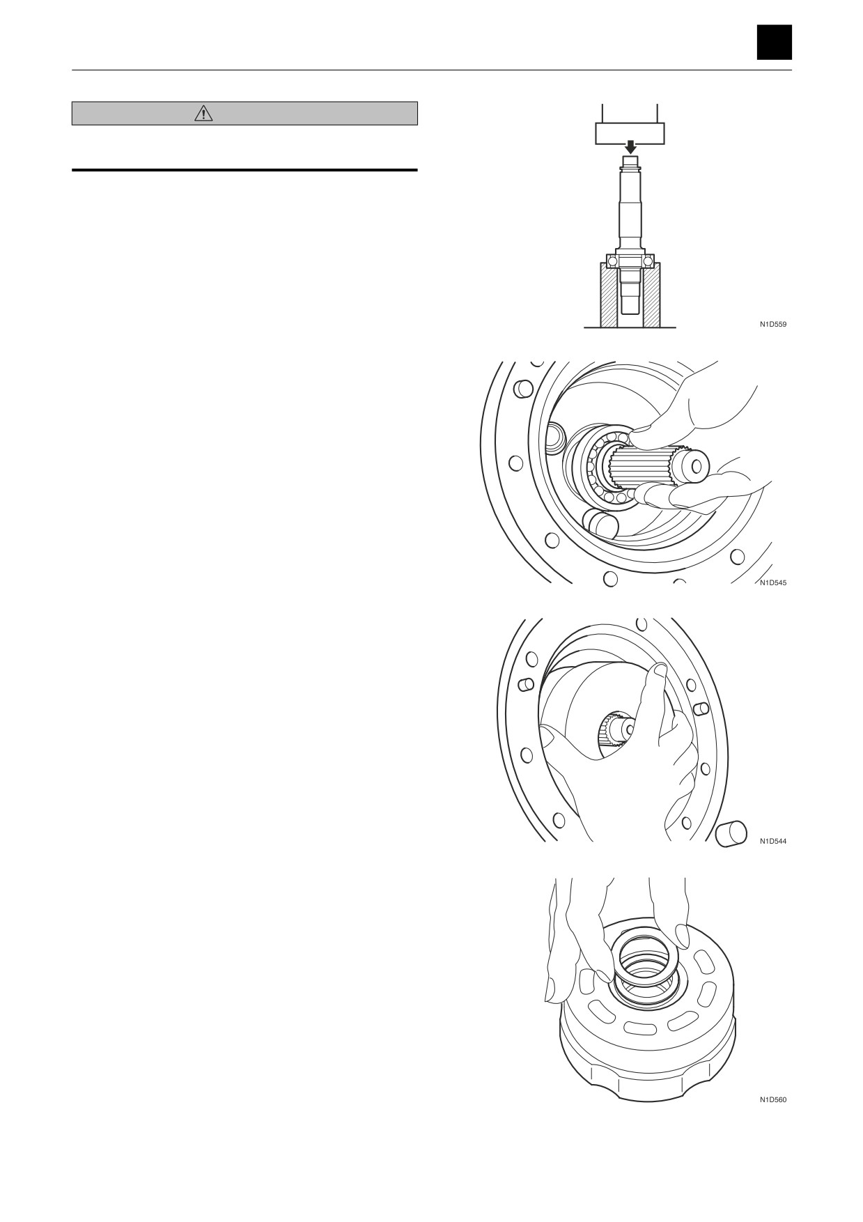
15. Attach the bearing to the shaft.
a. Place the bearing in the heating tank and heat it
at 100°C ± 10°C for ten minutes.
b. Use the press-fitting jig G to press-fit the bearing
into the shaft.
16. Attach the shaft to the motor housing.
• Take care not to damage the oil seal.
17. Insert the swash plate into the motor housing.
a. Grease the surfaces of the swash plate and motor
housing that make contact with each other.
b. Line up the holes on the swash plate with the piv-
ots inserted into the motor housing when inserting
the swash plate.
18. Insert the parts into the cylinder block in the order of
washer, spring, second washer, and then snap ring.
• Insert with the sharp corner of the snap ring ori-
ented toward the inlet port side.
• Insert with the sharp corner of the washer that
make contact with the snap ring oriented toward
the snap ring.
21
TRAVEL MOTOR
4M0AS00
DISASSEMBLY AND ASSEMBLY
TRAVEL MOTOR 4
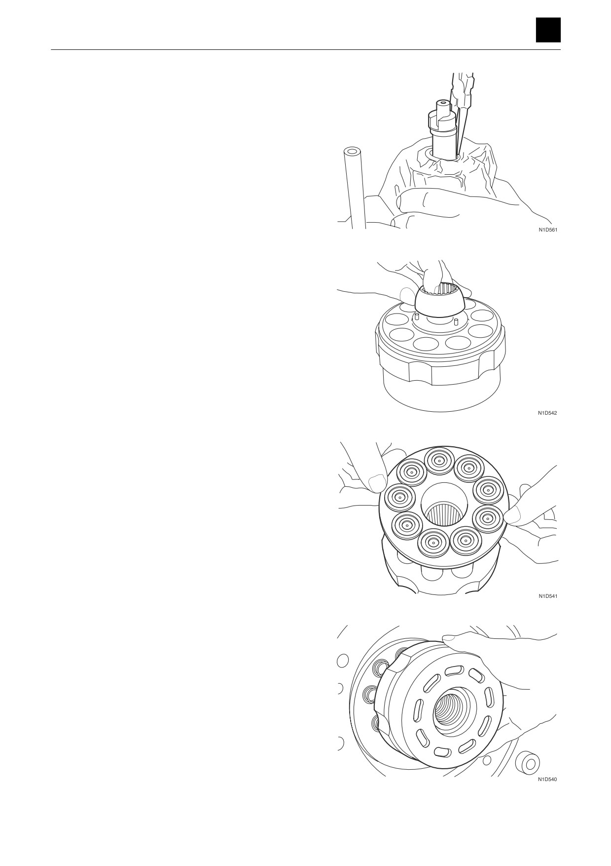
19. Insert the snap ring into the groove on the cylinder
block.
• Place the press-fitting jig H onto the washer, and
press the press-fitting jig H down onto the washer
using the press machine.
• Use pliers to insall the snap ring.
20. Attach the three pins to the cylinder block, and place
the guide on top of the pins.
21. Insert the nine piston assemblies into the shoe holder
and then insert the shoe holder with piston assem-
blies into the cylinder block.
• Dip the shoe holder with inserted piston assem-
blies into hydraulic oil before inserting into the cyl-
inder block.
22. Attach the cylinder block to the shaft.
• After placing the cylinder block onto the shaft,
turn the cylinder block with a hand to check for
looseness.
Inspect the cylinder block closely if there is any
looseness found.
22
TRAVEL MOTOR
4M0AS00
DISASSEMBLY AND ASSEMBLY
TRAVEL MOTOR 4
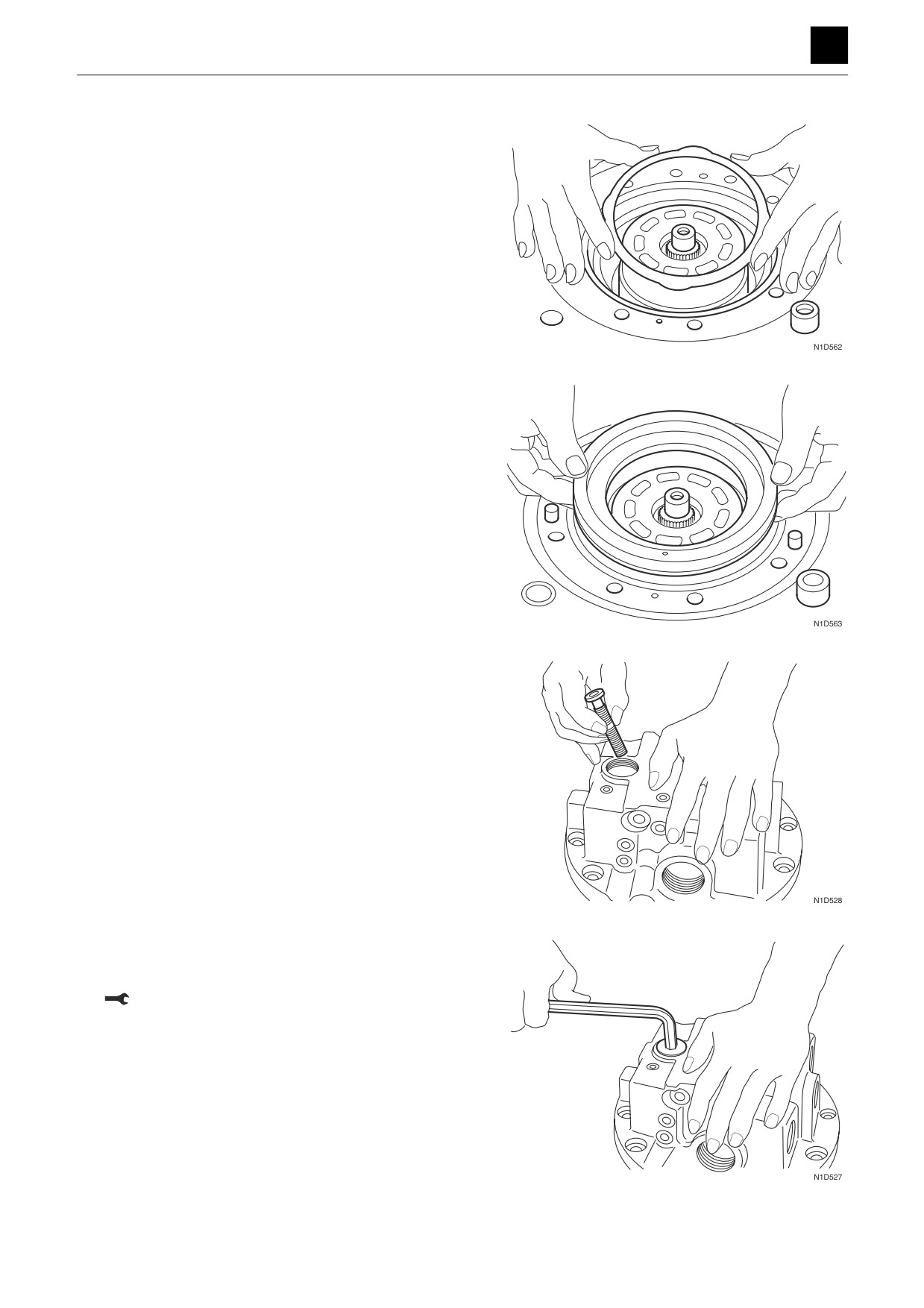
23. Place the four center discs and three friction discs on
the cylinder block in an alternating fashion, as in cen-
ter disc then friction disc and then center disc and so
on.
• Dip the friction discs in hydraulic oil before plac-
ing them on the cylinder block.
24. Grease the O-rings, and place them on the brake
piston.
25. Insert the brake piston into the motor housing.
26. Insert the spring and spool into the valve.
27. Grease the O-ring, and attach it to the plug.
28. Insert the plug into the valve body.
Plug: 98.1 N·m ± 19.6 N·m
23
TRAVEL MOTOR
4M0AS00
DISASSEMBLY AND ASSEMBLY
TRAVEL MOTOR 4
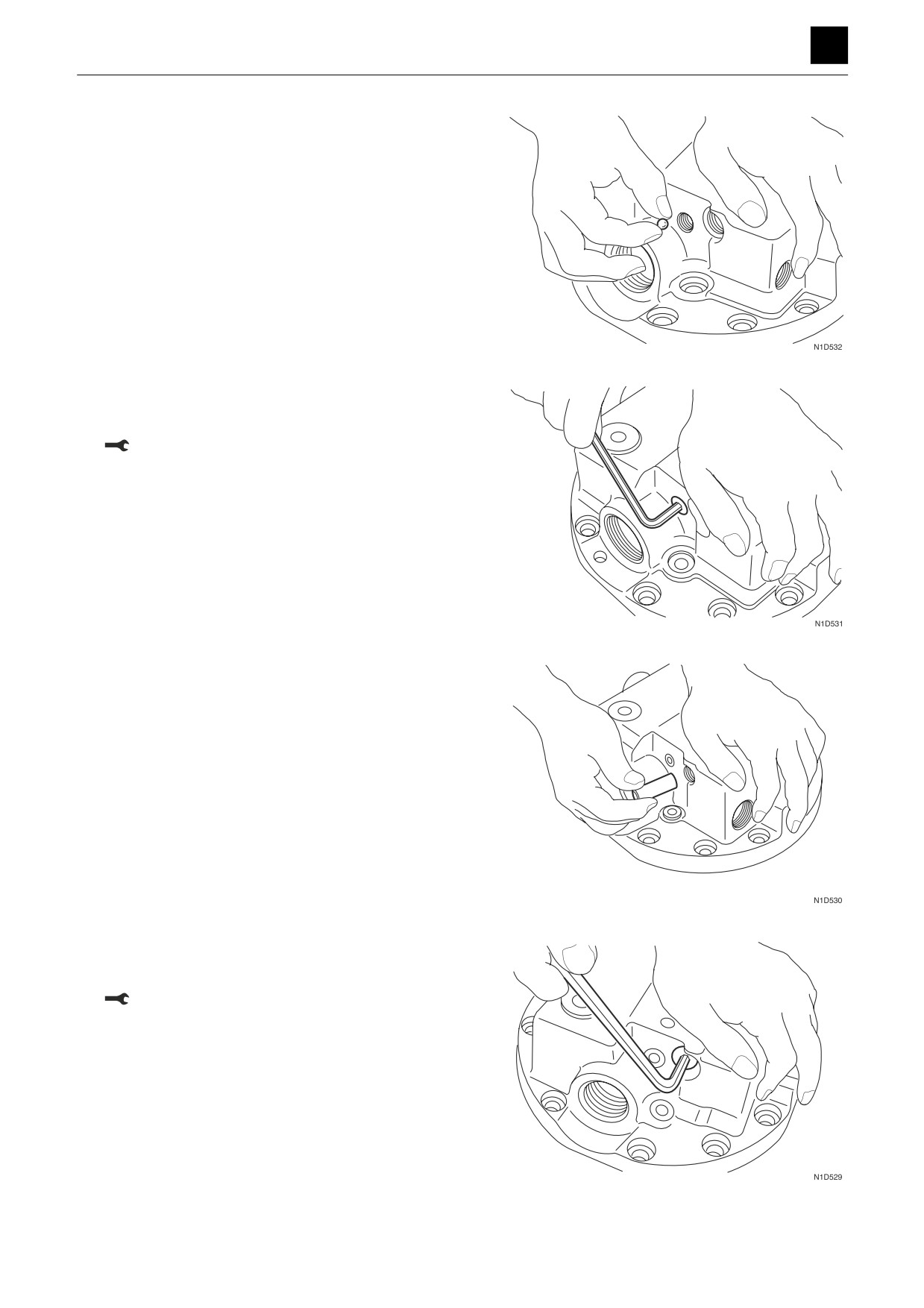
29. Insert the steel balls into the valve body.
30. Grease the O-ring, and attach it to the plug.
31. Insert the plug into the valve body.
Plug: 12.3 N·m ± 2.45 N·m
32. Attach the piston to the valve body.
33. Grease the O-ring, and attach it to the plug.
34. Insert the plug into the valve body.
Plug: 58.8 N·m ± 9.81 N·m
24
TRAVEL MOTOR
4M0AS00
DISASSEMBLY AND ASSEMBLY
TRAVEL MOTOR 4
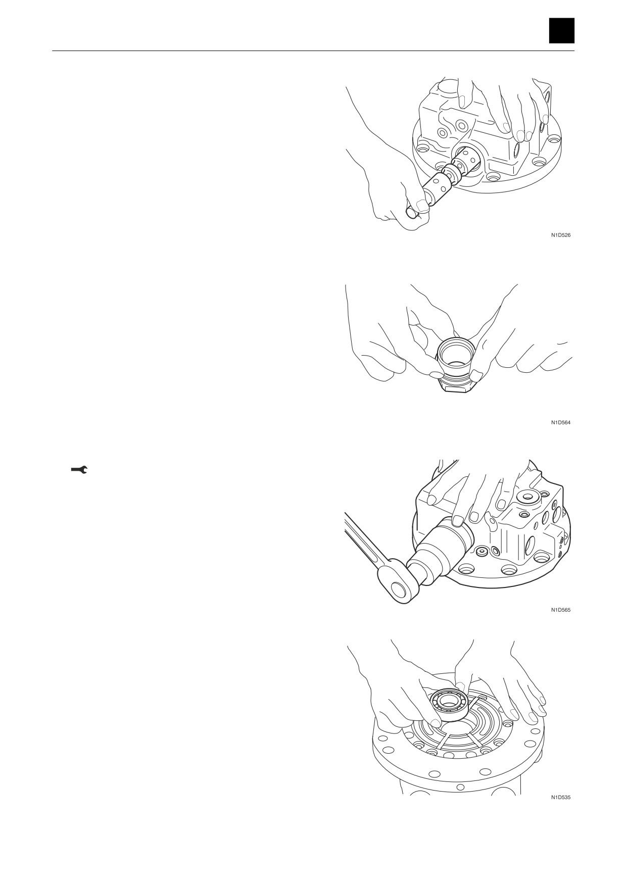
35. Grease the spool, and attach it to the valve body.
36. Grease the O-ring, and attach it to the plug.
37. Attach the washer and spring to the O-ring.
38. Insert the plug into the valve body.
Plug: 441 N·m ± 39.2 N·m
39. Insert the bearing into the valve body.
• Grease the bearing with hydraulic oil before in-
serting it.
40. Insert the pin into the pin hole on the valve body.
25
TRAVEL MOTOR
4M0AS00
DISASSEMBLY AND ASSEMBLY
TRAVEL MOTOR 4
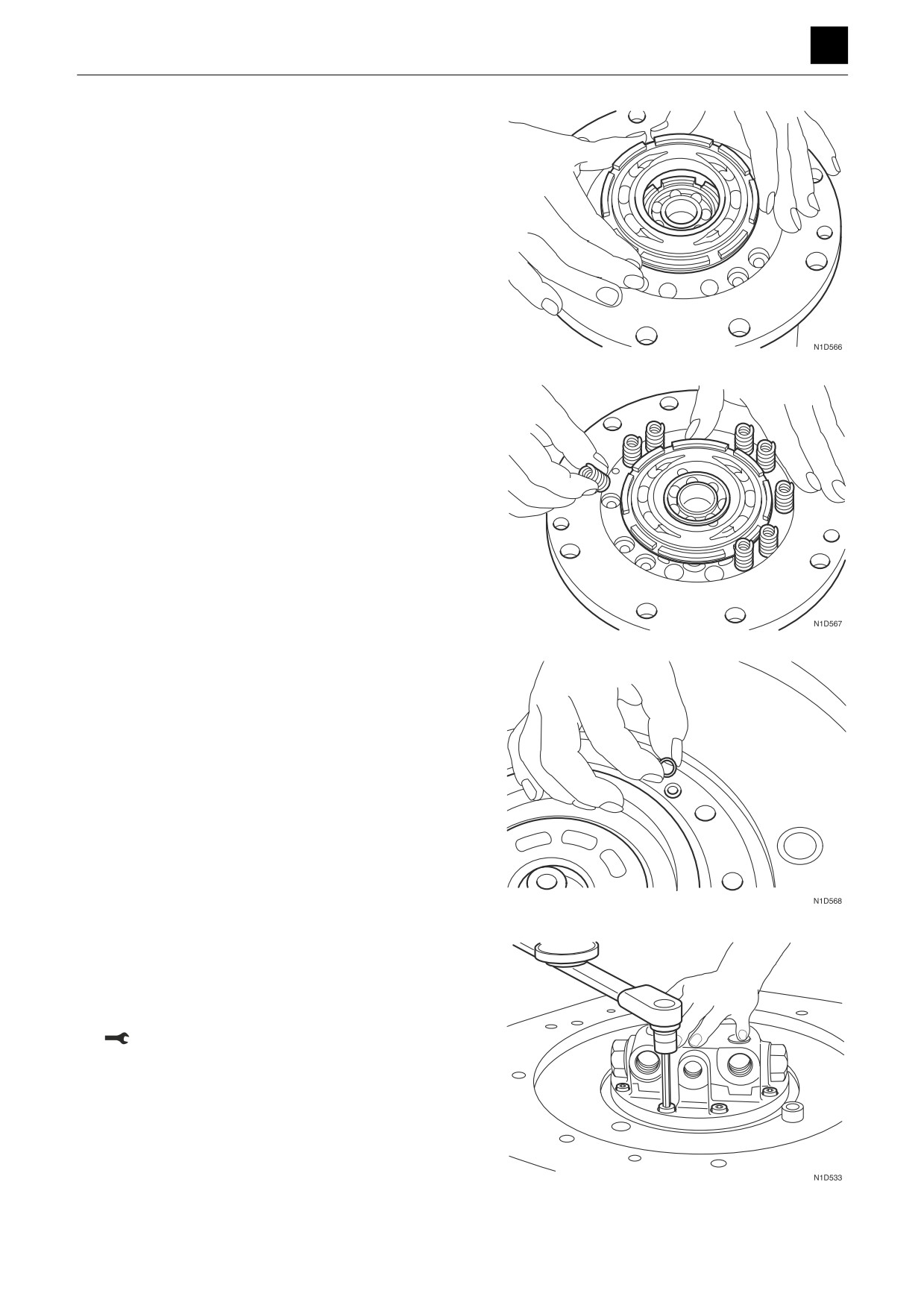
41. Attach the valve plate to the valve body.
• Grease the surfaces of the valve plate and valve
body that make contact with each other.
• Insert the pin into the guide, and attach the valve
plate.
42. Insert the ten springs into the valve body.
• Thoroughly grease the springs to prevent them
from falling out of the valve body.
43. Insert the large O-ring and two small O-rings into the
motor housing.
44. Pour 1 L of hydraulic oil into the motor housing.
45. Insert the valve body into the motor housing.
• Line up the pin holes on the valve body with the
two pins to insert the valve body.
46. Screw in the ten cap screws.
Cap screw: 102 N·m ± 15.7 N·m
26
TRAVEL MOTOR
4M0AS00
DISASSEMBLY AND ASSEMBLY
TRAVEL MOTOR 4
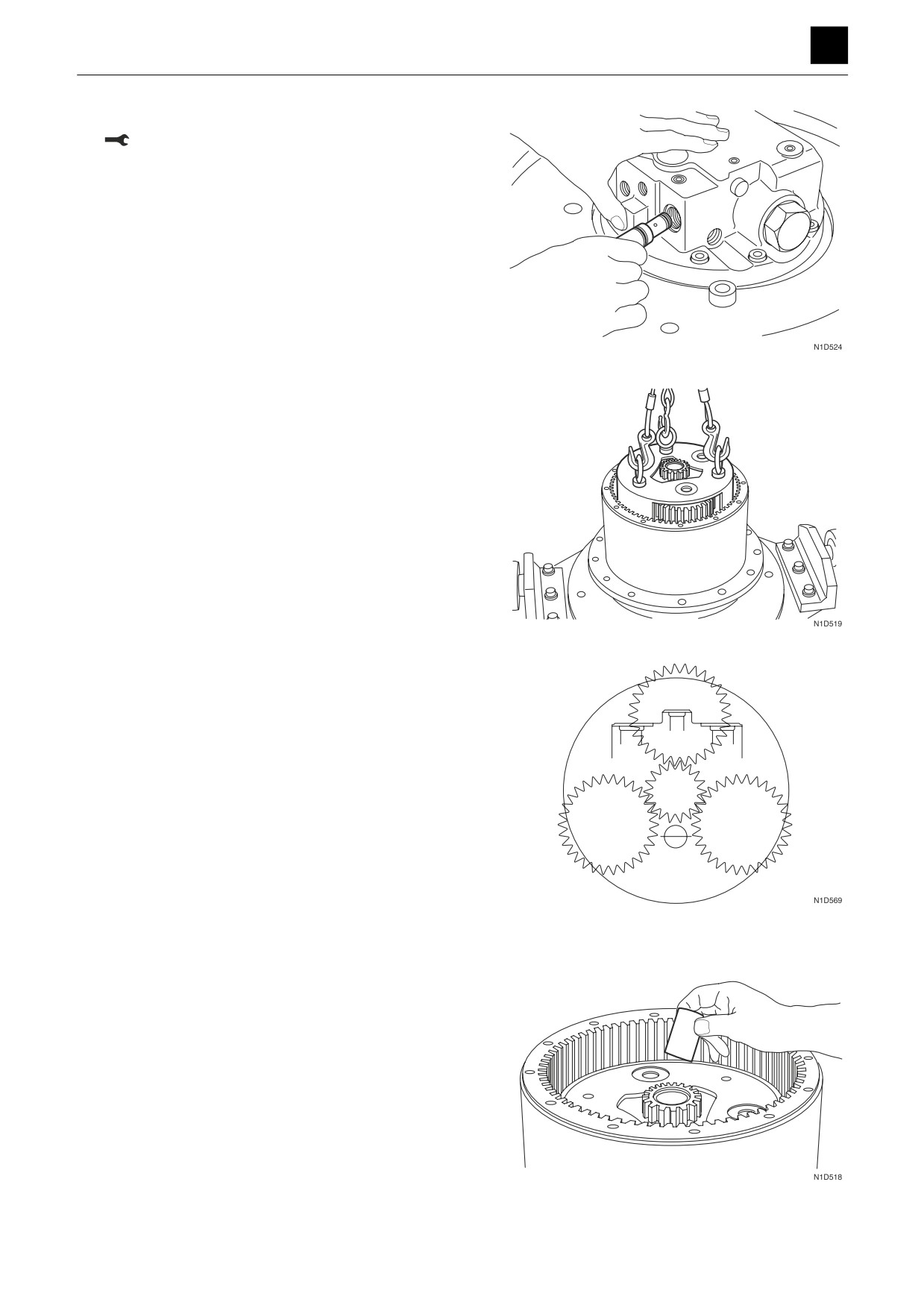
47. Insert the two relief valve assemblies.
Relief valve assembly: 98.1 N·m to 19.6 N·m
48. Attach the sun gear to the planet gear.
49. Insert the planet gear assembly into the gear case.
• Attach with the planet gear and valve body ports
oriented as shown in the diagram at left.
50. Attach the coupling to the drive shaft.
27
TRAVEL MOTOR
4M0AS00
DISASSEMBLY AND ASSEMBLY
TRAVEL MOTOR 4
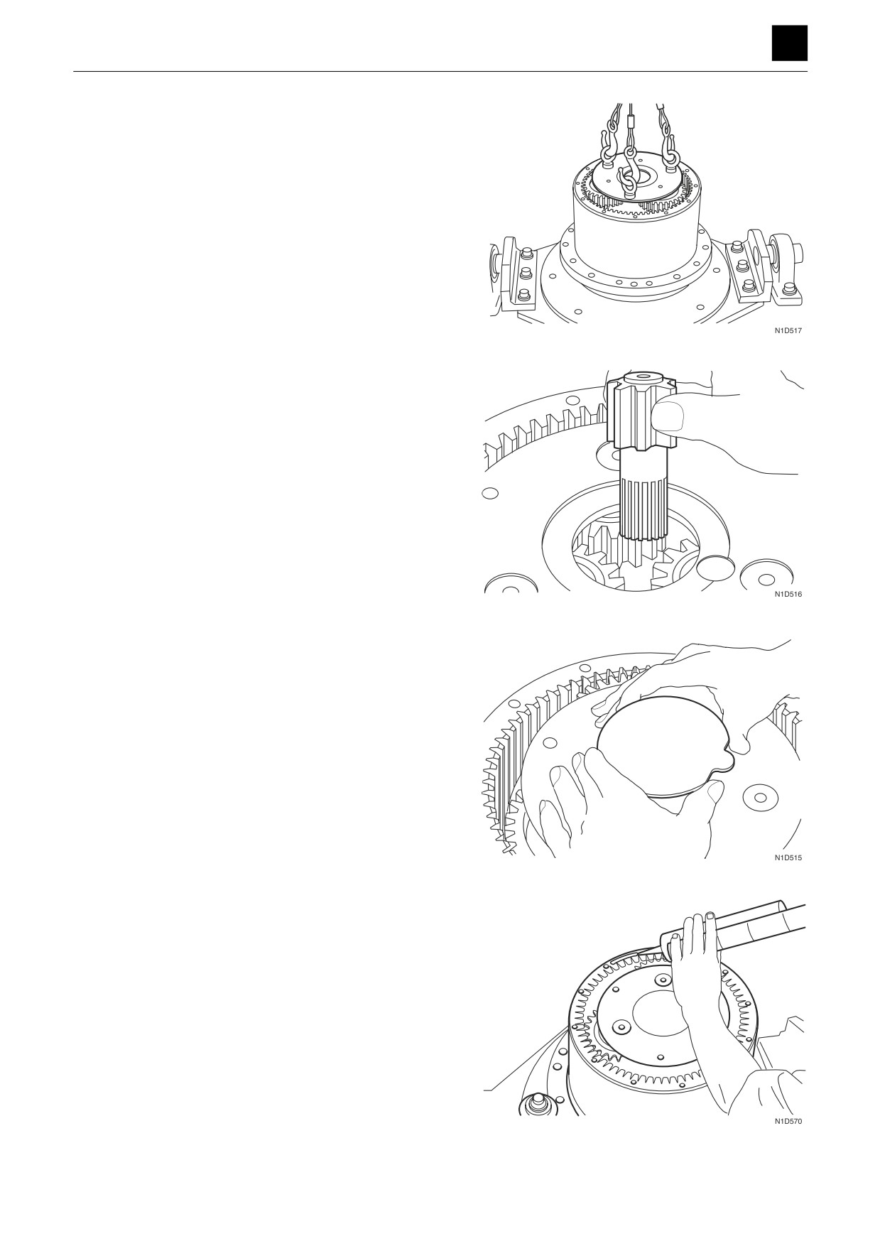
51. Insert the planet gear assembly into the gear case.
52. Attach the sun gear to the coupling.
• Attach the sun gear so that it lines up with the po-
sition of the spline.
53. Attach the thrust plate to the planet gear assembly.
54. Apply sealant to the surface that is to contact the
cover on the gear case.
• Apply the sealant evenly so as not to leave seams
or openings.
Sealant: Loctite #515
28
TRAVEL MOTOR
4M0AS00
DISASSEMBLY AND ASSEMBLY
TRAVEL MOTOR 4
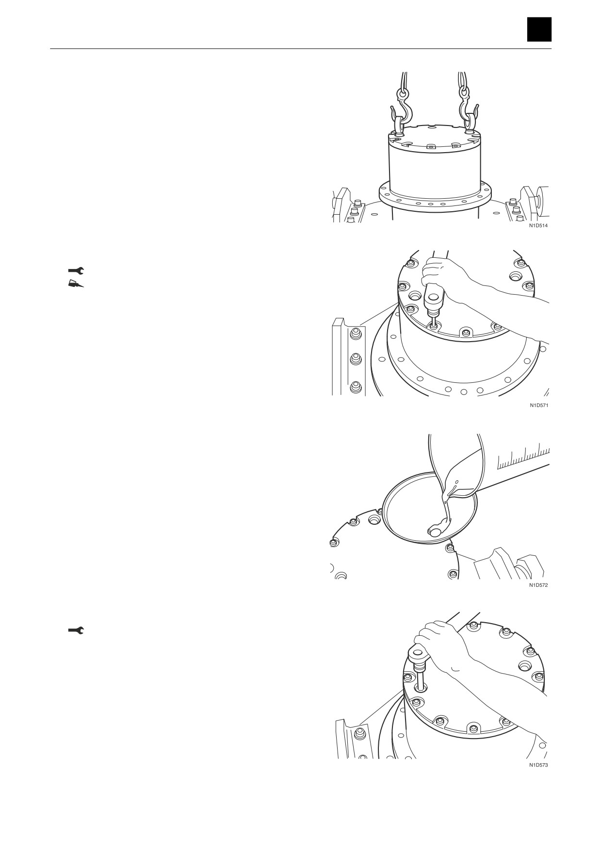
55. Attach the cover to the gear case.
56. Screw in the cap screws.
Cap screw: 66.7 N·m ± 3.92 N·m
Cap screw: Loctite #242
57. Pour 2.1 L of gear oil into the gear case to fill it.
58. Insert the plug into the cover.
Plug: 98.1 N·m ± 19.6 N·m
29
TRAVEL MOTOR
4M0AS00
DISASSEMBLY AND ASSEMBLY
TRAVEL MOTOR 4
Inspection and adjustments
Checking the parts
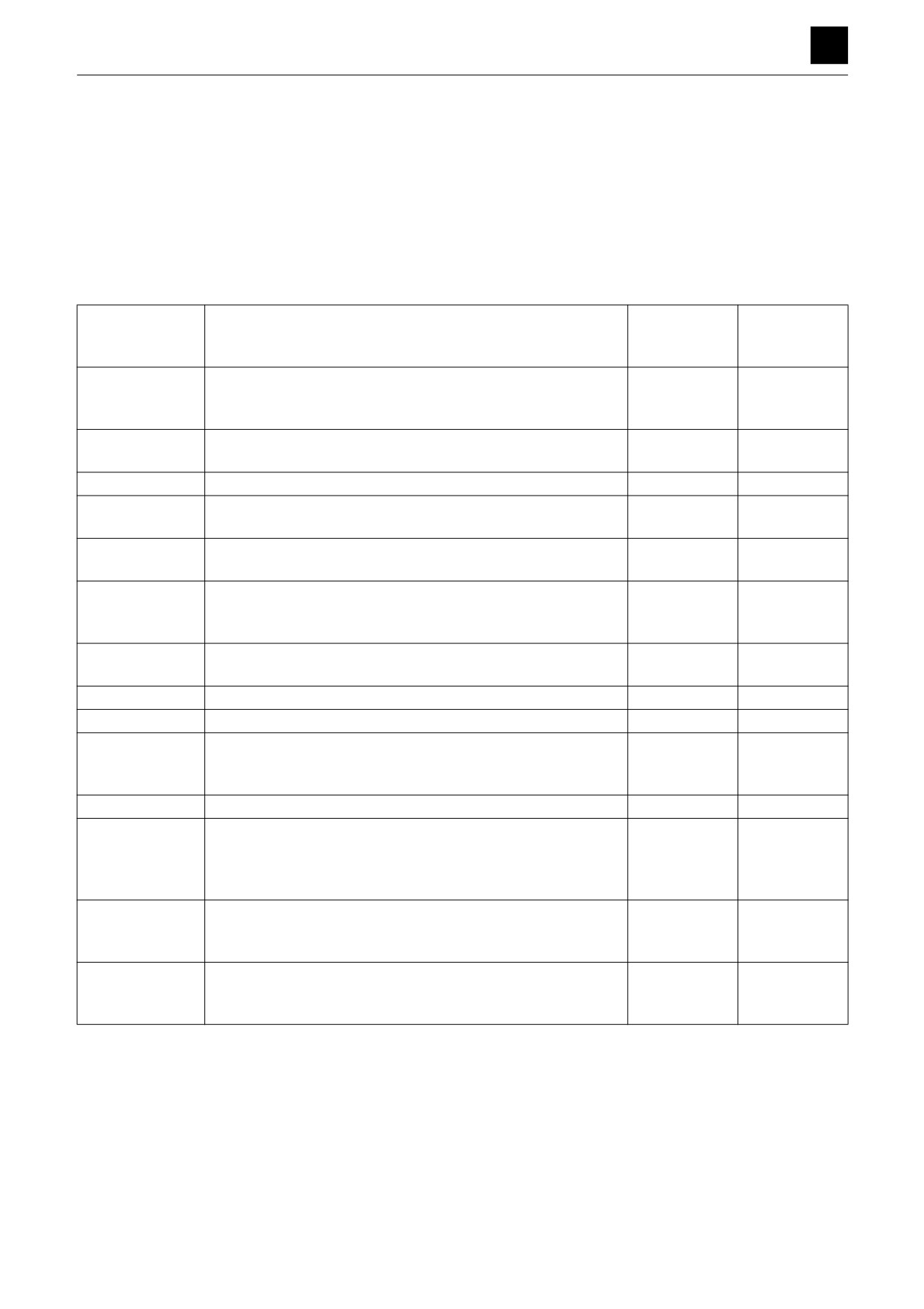
• Seal parts (O-rings, oil seals, floating seals) are to be
replaced with entirely new parts if removed during as-
sembly even if no damage is seen.
• All should be replaced if there is any notable damage
to the part exterior.
• Replace parts if any of the abnormalities (problem) list-
ed in the table below can be seen.
Standard value
Allowable value
Part name
Problem seen
(Standard di-
(Criteria)
mension)
Hub
•
Severe damage to the exterior.
—
—
•
Pitting occurring on the surface of the ring gear teeth.
•
Abnormal wear occurring such as seizure, etc.
Spindle
•
Severe damage to the exterior.
—
—
•
Abnormal wear occurring such as seizure, etc.
Carrier assembly
•
Abnormal wear occurring such as seizure, etc.
—
—
Sun gear
•
Pitting occurring on the surface of the teeth.
—
—
Planetary gear
•
Flaking occurring on the rolling surfaces of the bearings.
Thrust washers
•
Discoloration or abnormal wear occurring on the sliding sur-
—
—
faces.
Main bearings
•
Indentations seen.
—
—
•
Flaking occurring.
•
Extreme amounts of abnormal wear observed.
Needle bearings
•
Pitting occurring in the rolling surfaces.
—
—
•
Abnormal wear occurring on the retainer end surfaces.
Inner rings
•
Flaking occurring on the rolling surfaces of the bearings.
—
—
Rear flange
•
Damage occurring on the sliding surfaces with the spool.
—
—
Shaft
•
Wear occurring on the surface that make contact with the oil
—
—
seal.
•
Wear occurring in the spline.
Swash plate
•
Seizure occurring.
—
—
Cylinder block
•
Wear occurring in the spline.
—
—
•
High level of wear occurring on the inner surface of the bore.
•
Damage and wear occurring on the sliding surfaces with the
valve plate.
Piston assembly
•
A clearance observed between the piston and shoe in the ax-
Clearance
Clearance
Shoe
ial direction.
0.05 mm
0.15 mm
•
Abnormal wear and extreme wear occurring in the shoe.
Retainer plate
•
Extreme wear occurring on the sliding surfaces with the shoe.
—
—
•
Damage and extreme wear occurring on the sliding surfaces
with the guide.
30
TRAVEL MOTOR
4M0AS00
DISASSEMBLY AND ASSEMBLY
TRAVEL MOTOR 4
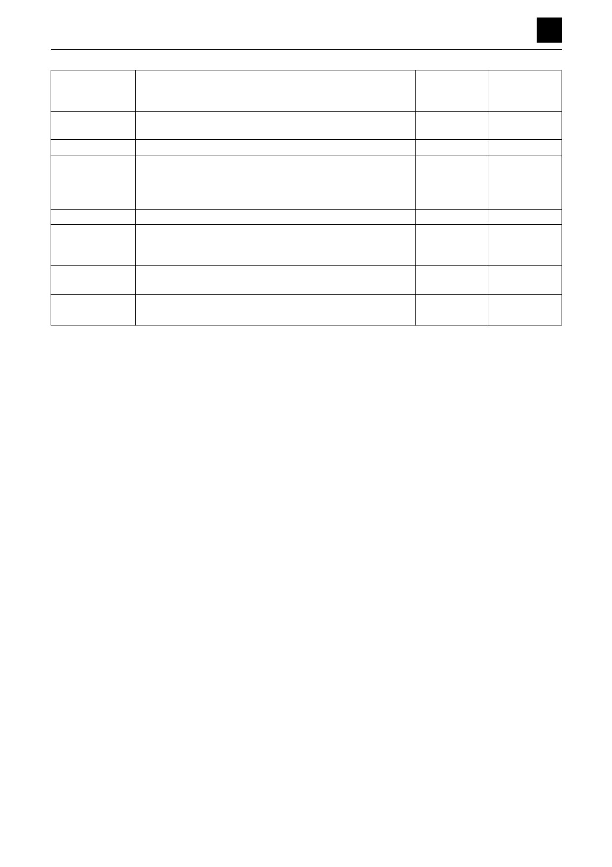
Standard value
Allowable value
Part name
Problem seen
(Standard di-
(Criteria)
mension)
Thrust ball
• Extreme wear occurring on the hemispherical sliding surfac-
—
—
es with the retainer plate.
Valve plate
• Seizure and extreme wear occurring on the rolling surfaces.
—
—
Friction disc
• Extreme wear occurring on each end.
Damping
Damping
Other discs
• Specified torque not met.
torque,
torque,
• Seizure occurring.
206 N·m or
206 N·m or
above
above
Piston
• Scratches observed in the outer circumference.
—
—
Bearings
• Indentations seen.
—
—
• Flaking occurring.
• Wear occurring.
2nd-speed piston
• Abnormal wear occurring in the outer circumference.
—
—
Shoe
• Abnormal wear and extreme wear occurring in the shoe.
Spool
• Abnormal wear occurring in the outer circumference.
—
—
• Scratches observed in the outer circumference.
31
TRAVEL MOTOR
4M0AS00
DISASSEMBLY AND ASSEMBLY
TRAVEL MOTOR 4
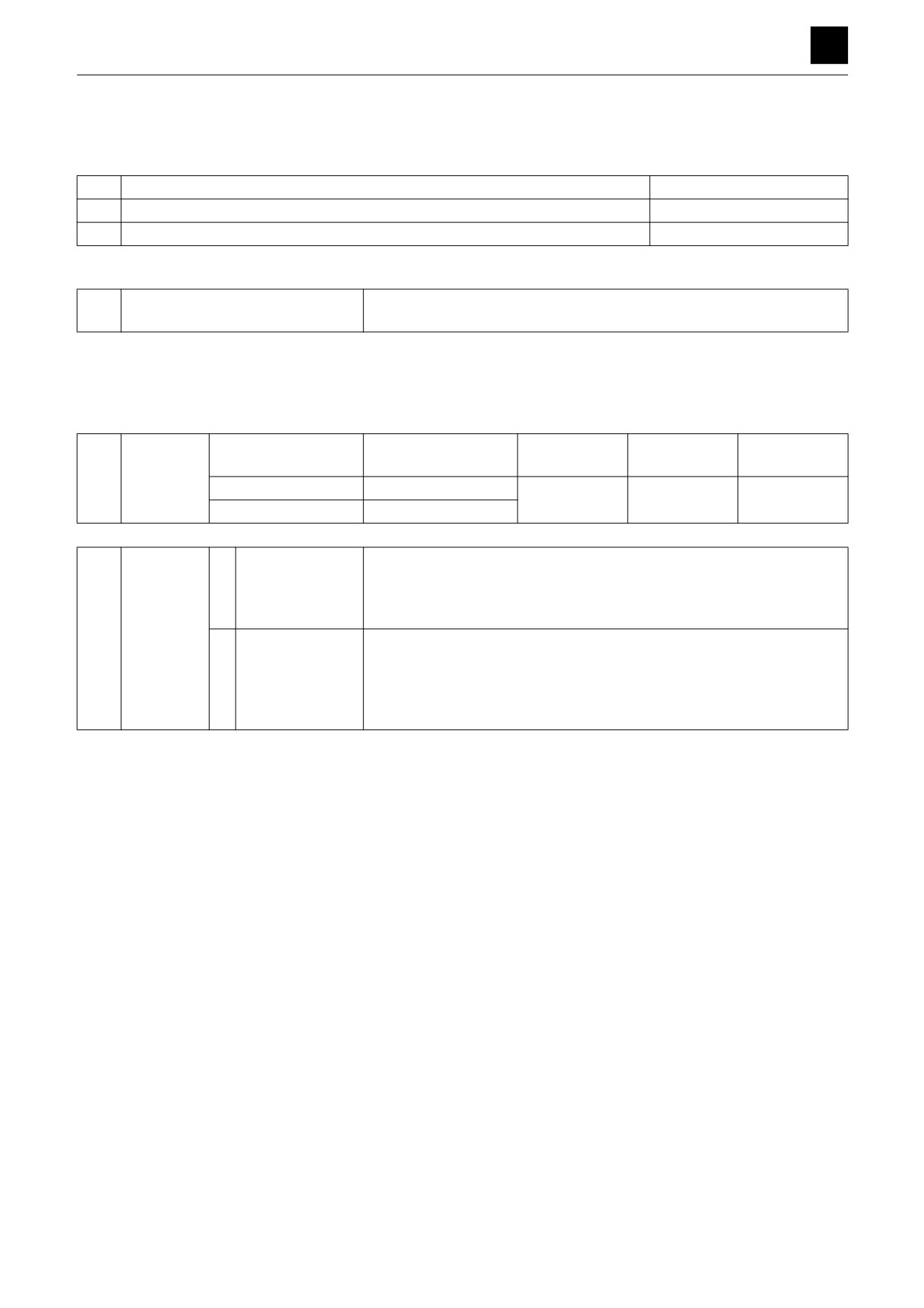
Performance Verification Testing
After completing travel motor installation, conduct performance verification testing using the procedures listed below.
1. Required measurement equipment
1
Pressure gauges (3.43 MPa readings)
Qty. 2
2
Graduated cylinder (Up to 5 L)
Qty. 1
3
Stopwatch
Qty. 1
2. Test procedures
1
Motor installation and piping work
Insert the travel motor into the machine and connect the piping.
Do not attach the crawler.
Notes)
1) When making piping connections, connect the piping so that the pressure gauges (main circuit) can be installed
and the drain volume from the hydraulic motor can be measured.
2) When installing the travel motor, do not tap it with a hammer or other part; instead, install using the bolt holes.
2
Idling of the
Switching
Travel motor rotation
Pressure
Direction of ro-
Operating time
travel motor
speed
tation
Low-speed rotation
10 min-1
Without load
Left/right
At least 1 min.
High-speed rotation
20 min-1
per type
3
Travel mo-
1
Pre-test prepara-
Run the travel motor to warm it up until the temperature ranges listed be-
tor perfor-
tions
low have been reached.
mance veri-
• Hydraulic oil temp.: 45°C to 55°C
fication
• External reduction gear hub temp.: 40°C to 80°C
testing
2
Verification test
The travel motor unit is considered to have passed if the criteria for pass-
ing listed below are met for low-speed operation.
Criteria for passing
• Pressure differential for travel motor driving: 1.57 MPa or less/10 min-1
• Hydraulic motor drain volume: 1.2 L/min-1 or less/10 min-1
If the unit does not satisfy the requirements to pass the test, disassemble and make adjustments, and then test again.
32
TRAVEL MOTOR
4M0AS00
DISASSEMBLY AND ASSEMBLY
SLEW MOTOR 4
SLEW MOTOR
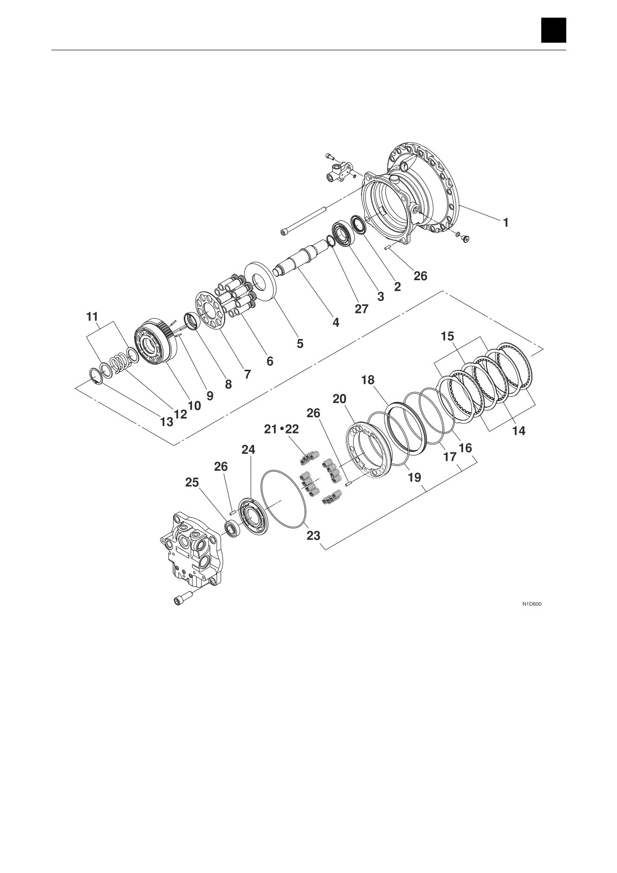
Construction
Hydraulic motor
1. Motor housing
10. Cylinder block
19. O-ring
2. Oil seal
11. Washer
20. Break piston
3. Bearing
12. Spring
21. Spring
4. Shaft
13. Snap ring
22. Spring
5. Swash plate
14. Friction disc
23. O-ring
6. Piston assembly
15. Center disc
24. Valve plate
7. Shoe holder
16. O-ring
25. Bearing
8. Guide
17. O-ring
26. Pin
9. Pin
18. Collar
27. Snap ring
1
SLEW MOTOR
4N0AS00
DISASSEMBLY AND ASSEMBLY
SLEW MOTOR 4
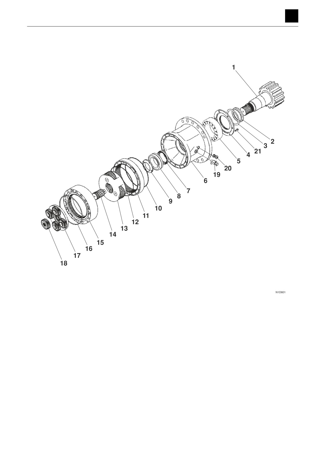
Reduction gears
1. Pinion shaft
8. Bearing
15. Ring gear
2. Collar
9. Nut
16. O-ring
3. Seal
10. O-ring
17. Planet gear
4. Cover
11. Ring gear
18. Sun gear
5. Bearing
12. O-ring
19. Valve
6. Case
13. Planet gear
20. Plug
7. Oil seal
14. Sun gear
21. Screw
2
SLEW MOTOR
4N0AS00
DISASSEMBLY AND ASSEMBLY
SLEW MOTOR 4
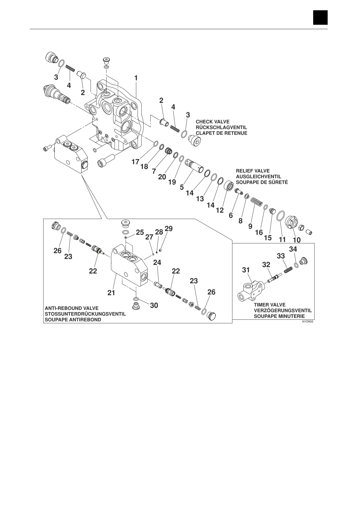
Brake valve
1. Valve body
13. O-ring
25. Orifice
2. Poppet
14. Backup ring
26. O-ring
3. O-ring
15. Guide
27. Filter
4. Spring
16. O-ring
28. Washer
5. Housing
17. O-ring
29. Orifice
6. Poppet
18. Backup ring
30. O-ring
7. Seat
19. O-ring
31. Valve body
8. Seat
20. Backup ring
32. Spool
9. Spring
21. Valve body
33. Spring
10. Plug
22. Check valve assembly
34. O-ring
11. O-ring
23. Spring
12. Piston
24. Sleeve
3
SLEW MOTOR
4N0AS00
DISASSEMBLY AND ASSEMBLY
SLEW MOTOR 4
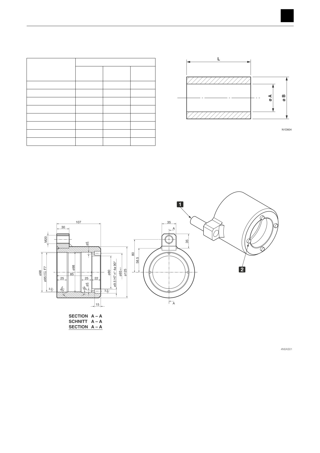
Special tools
Press-fitting jigs (A) to (H)
Dimensions (mm)
Items
A (Inner
B (Outer
L
diameter)
diameter)
(Length)
Press-fitting jig (A)
47
90
170
Press-fitting jig (B)
160 ± 1
168.3
160
Press-fitting jig (C)
74 ± 1
82 ± 0.5
80
Press-fitting jig (D)
85 ± 1
94 ± 0.5
40
Press-fitting jig (E)
41
60
80
Press-fitting jig (F)
68
79
140
Press-fitting jig (G)
101.7 ± 1
114.3 ± 1
250
Press-fitting jig (H)
77 ± 0.5
128 ± 1
75
Stopper jig (I)
1 STUD BOLT M20×50 UNI 5911
2 ø9.5, m6, L = 20 mm
No. 4 pins at 90°
MATERIAL: 40CrMo4
HARDENED-TEMPERED
90/100 daN/mm2 CASE STRENGTH
4
SLEW MOTOR
4N0AS00
DISASSEMBLY AND ASSEMBLY
SLEW MOTOR 4
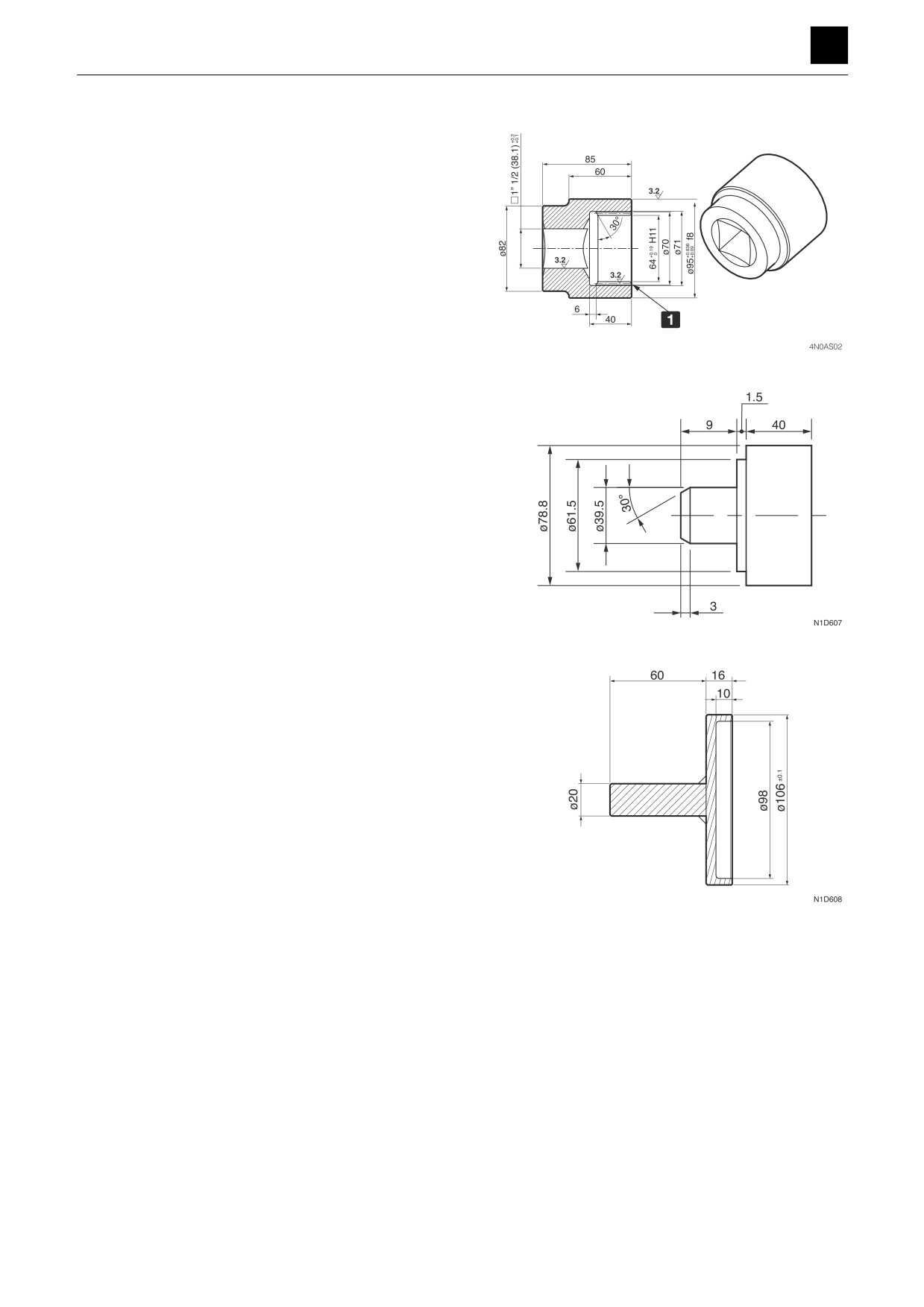
Socket jig (J)
Press-fitting jig (K)
Press-fitting jig (L)
5
SLEW MOTOR
4N0AS00
DISASSEMBLY AND ASSEMBLY
4
SLEW MOTOR
Disassembly and assembly
General precautions
• Perform disassembly and assembly work in a clean
place. Provide clean containers to hold parts during
disassembly.
• Clean around the ports before disassembly. Remove
paint around connectors with a wire brush.
• Clean the disassembled parts with wash oil.
• Put alignment marks on all parts to ensure that they are
reassembled in the same positions.
• After each disassembly, replace all seals and apply a
thin layer of grease to each.
• Check each part for abnormal wear or seizing. Re-
move any burrs with sandpaper.
• Remove adhesive from screw holes that use adhesive
through the tap. Do not reuse mounting bolts or
screws.
• Do not use cloth gloves during assembly. Fibers from
the gloves could fall off and clog valves, etc., which
could cause parts to become faulty.
• During assembly, be sure to apply clean hydraulic oil
to all moving parts in and sliding parts that come into
contact with the hydraulic motor and valve parts be-
fore installing or attaching the part.
• Plug all ports once assembly has been completed in
order to prevent dust and dirt from entering.
• Do not attempt to adjust the adjusting screws at times
other than when necessary.
Disassembly
Slew motor
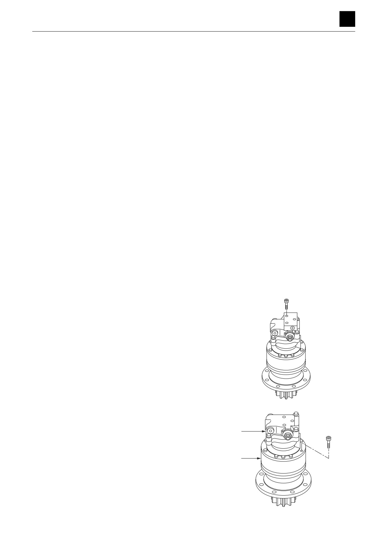
1. Remove the cap screws, and remove the reversal
prevention valve.
K3D626
2. Take out the cap screws, and disassemble the hy-
draulic motor (1) and reduction gears (2).
1
• Secure the hydraulic motor in place with a vice.
• Draw alignment marks on the hydraulic motor and
reduction gears to ensure that they are reassem-
bled in the same positions.
2
K3D627
6
SLEW MOTOR
4N0AS00
DISASSEMBLY AND ASSEMBLY
SLEW MOTOR 4
Brake valve and hydraulic motor
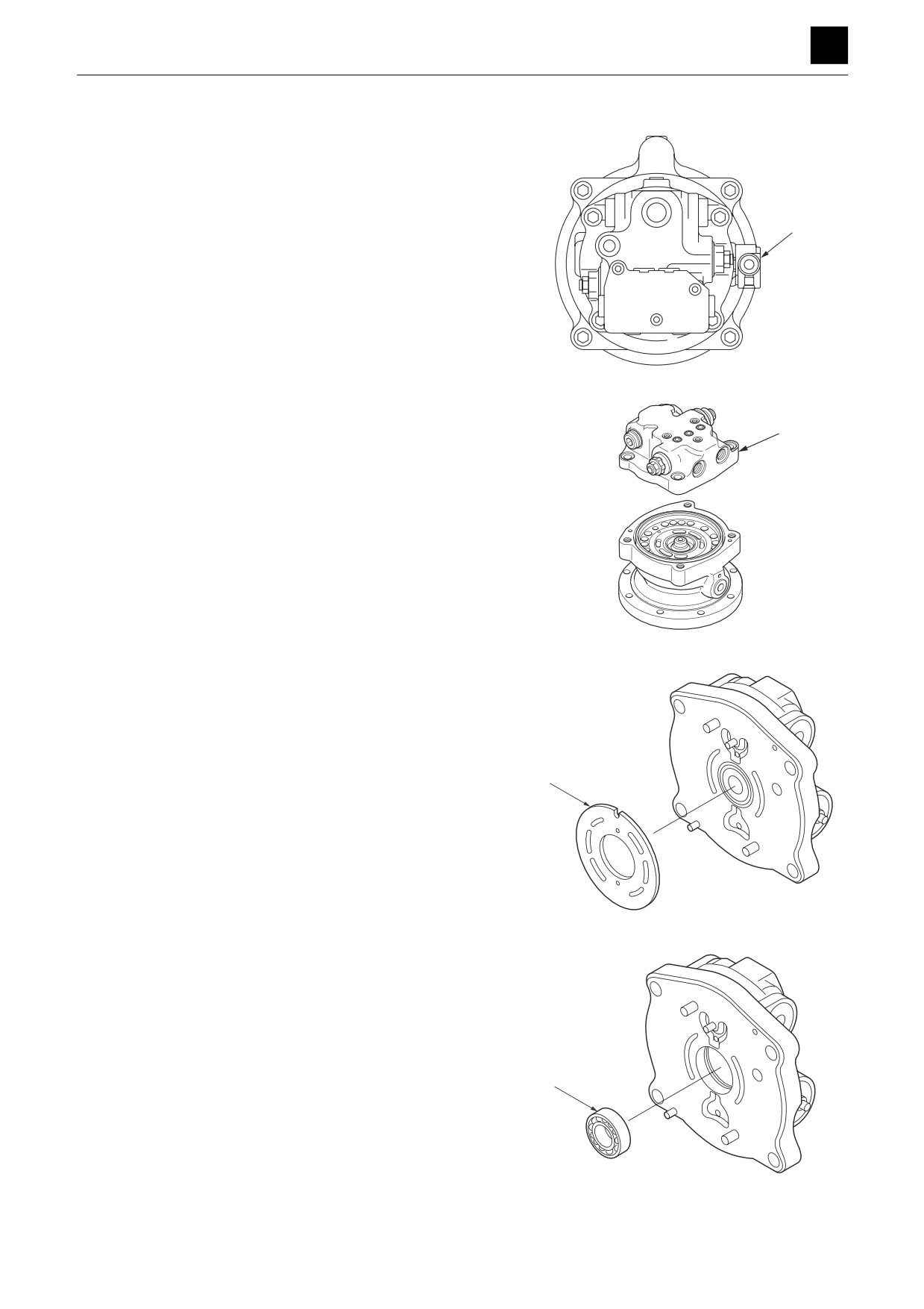
1. Take out the cap screws, and remove the timer valve
(1).
• Be careful not to lose the O-ring.
2. Take out the cap screws, and remove the valve body
(2).
• Secure the hydraulic motor in place with a vice.
• Be careful not to allow the valve plate to fall.
3. Remove the valve plate (3) from the valve body.
4. Remove the bearing (4).
• Do not remove unless it needs to be replaced.
7
SLEW MOTOR
4N0AS00
DISASSEMBLY AND ASSEMBLY
SLEW MOTOR 4
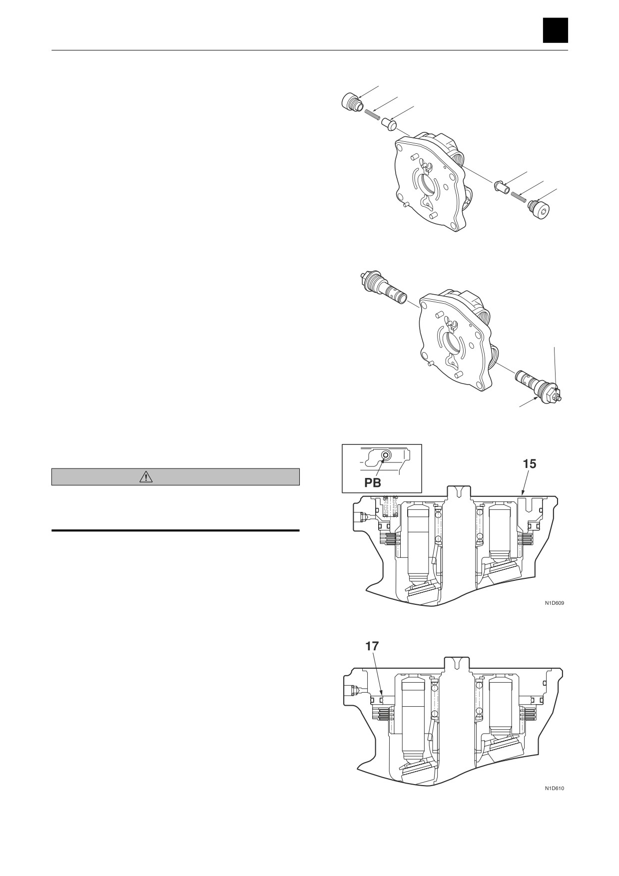
5. Remove the check valve.
a. Remove the plug (9).
b. Remove the spring (10) and the check valve (11).
6. Remove the relief valve.
• Do not loosen the set screw or the nut (13).
• Do not disassemble the relief valve.
7. Remove the brake piston (15).
WARNING
Metal fragments and other objects may scatter into the air
in work areas in which compressed air is used. Wear pro-
tective gear such as goggles and a protective face mask.
• Take precautions against the brake piston flying
out of the brake release port PB by increasing the
air pressure.
8. Remove the collar (17).
8
SLEW MOTOR
4N0AS00
DISASSEMBLY AND ASSEMBLY
SLEW MOTOR 4
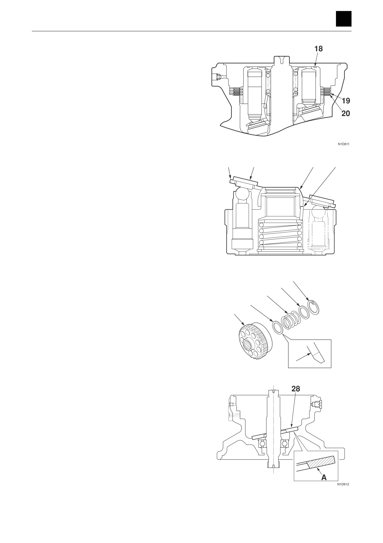
9. Remove the cylinder block (18), the friction discs
(19), and the center discs (20).
10. Remove the shoe holder (14) and piston assembly
(21) from the cylinder block.
11. Remove the guide (22) and pins (23) from the cylin-
der block.
12. Remove the snap ring (24), washer (25), spring (26),
24
25
and washer (27) from the cylinder block (18).
26
• Do not disassemble unless repair is needed.
27
• If repair is needed, replace the entire cylinder
block assembly.
18
A
E5D622
13. Remove the swash plate (28).
9
SLEW MOTOR
4N0AS00
DISASSEMBLY AND ASSEMBLY
SLEW MOTOR 4
14. Remove the pinion shaft (29).
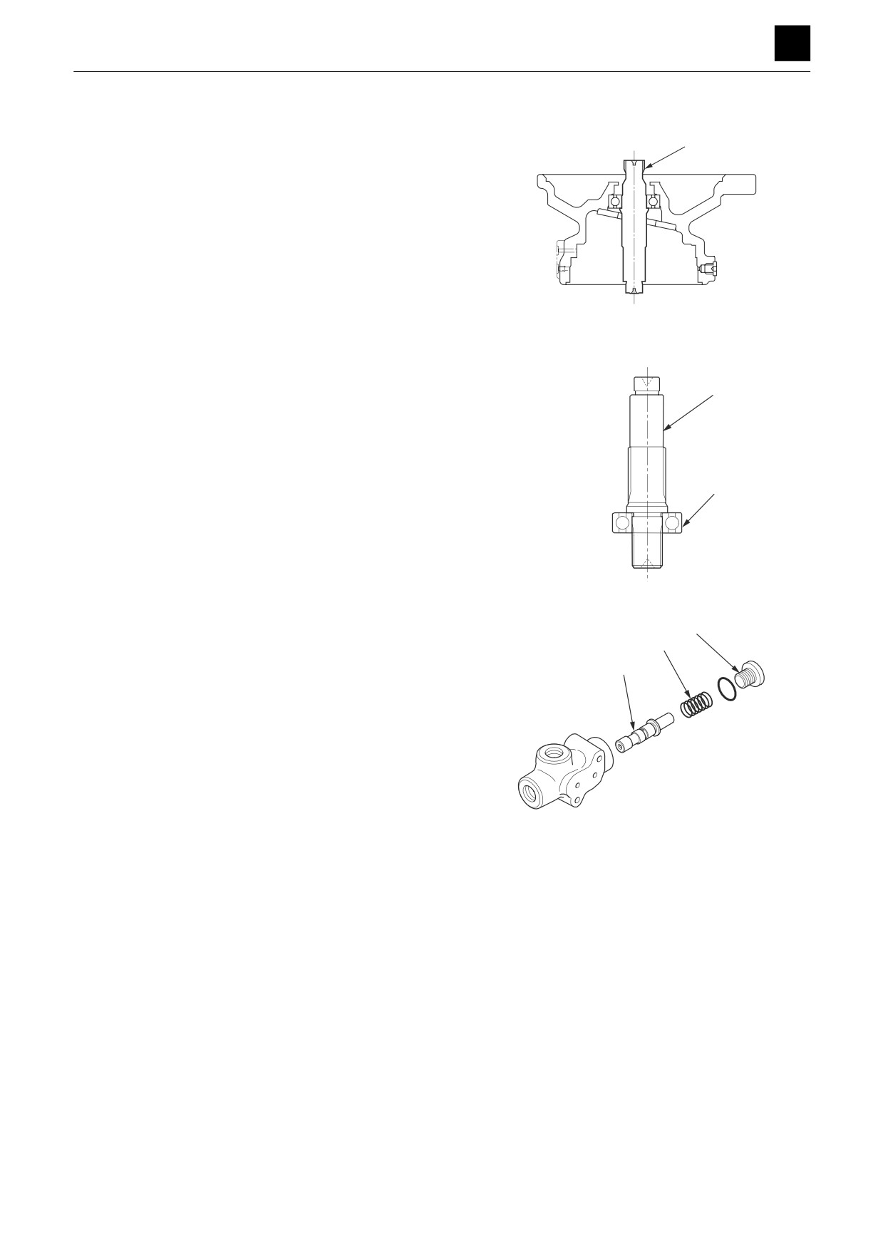
• If unable to remove the shaft easily, tap it lightly
with a plastic hammer.
15. Remove the bearing (30) from the pinion shaft (29)
29
using the press-fitting jig (A).
• Do not disassemble unless repair is needed.
• Bearings that have been removed cannot be re-
used and must be replaced.
30
K3D643
31
16. Remove the timer valve.
32
• Be careful not to damage attachment surfaces.
a. Remove the plug (31).
33
b. Remove the spring (32) and spool (33).
• Use a tweezers to remove the parts.
K3D644
10
SLEW MOTOR
4N0AS00
DISASSEMBLY AND ASSEMBLY
SLEW MOTOR 4
Reduction gears
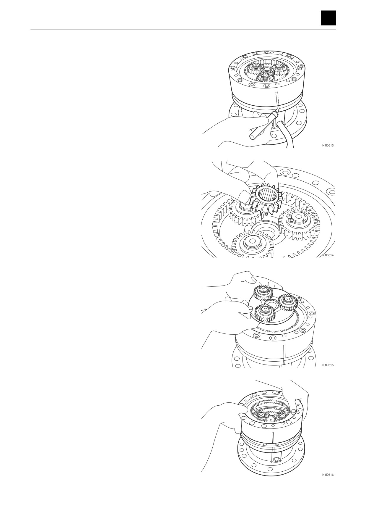
1. Place alignment marks on the ring gear and case be-
fore disassembling to ensure that the parts are as-
sembled back in their original positions.
2. Remove the sun gear.
3. Remove the 1st stage planet gear assembly.
4. Remove the ring gear.
11
SLEW MOTOR
4N0AS00
DISASSEMBLY AND ASSEMBLY
SLEW MOTOR 4
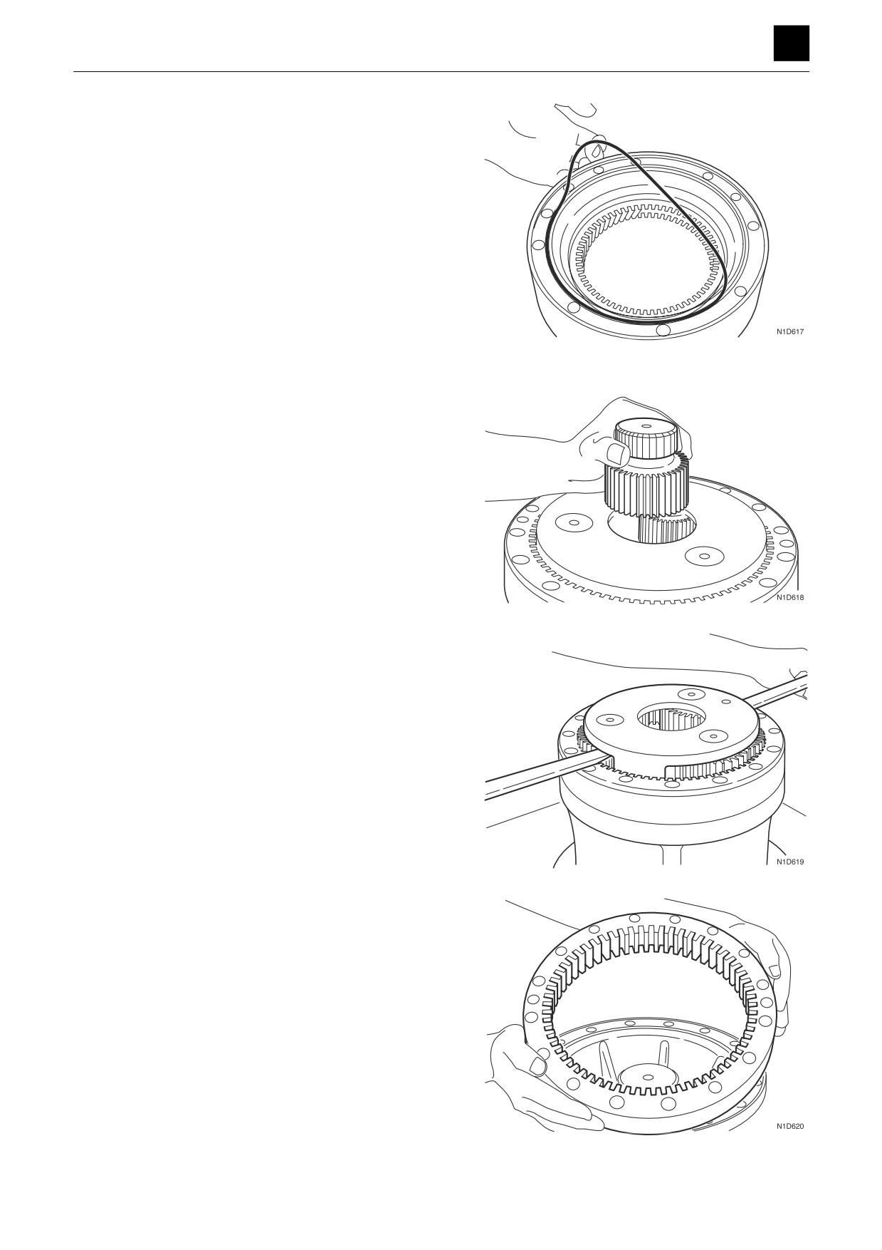
5. Remove the O-ring.
6. Remove the sun gear.
7. Remove the 2nd stage planet gear assembly.
8. Remove the ring gear.
12
SLEW MOTOR
4N0AS00
DISASSEMBLY AND ASSEMBLY
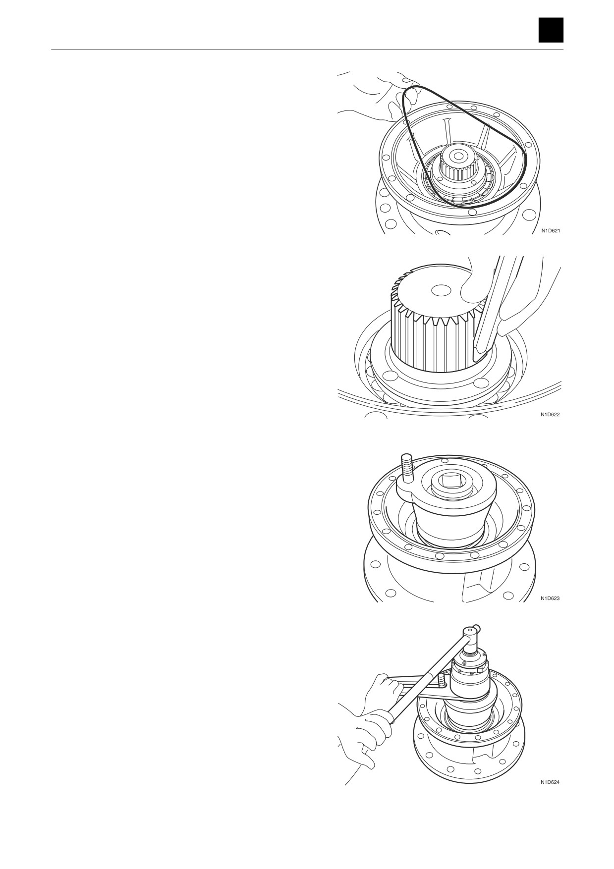
SLEW MOTOR 4
9. Remove the ring gear from the case.
10. Remove the crimping on the ring nut.
11. Attach the stopper jig (I) and socket jig (J) to the ring
nut.
12. Use a torque multiplier wrench to loosen the ring nut.
13
SLEW MOTOR
4N0AS00
DISASSEMBLY AND ASSEMBLY
SLEW MOTOR 4
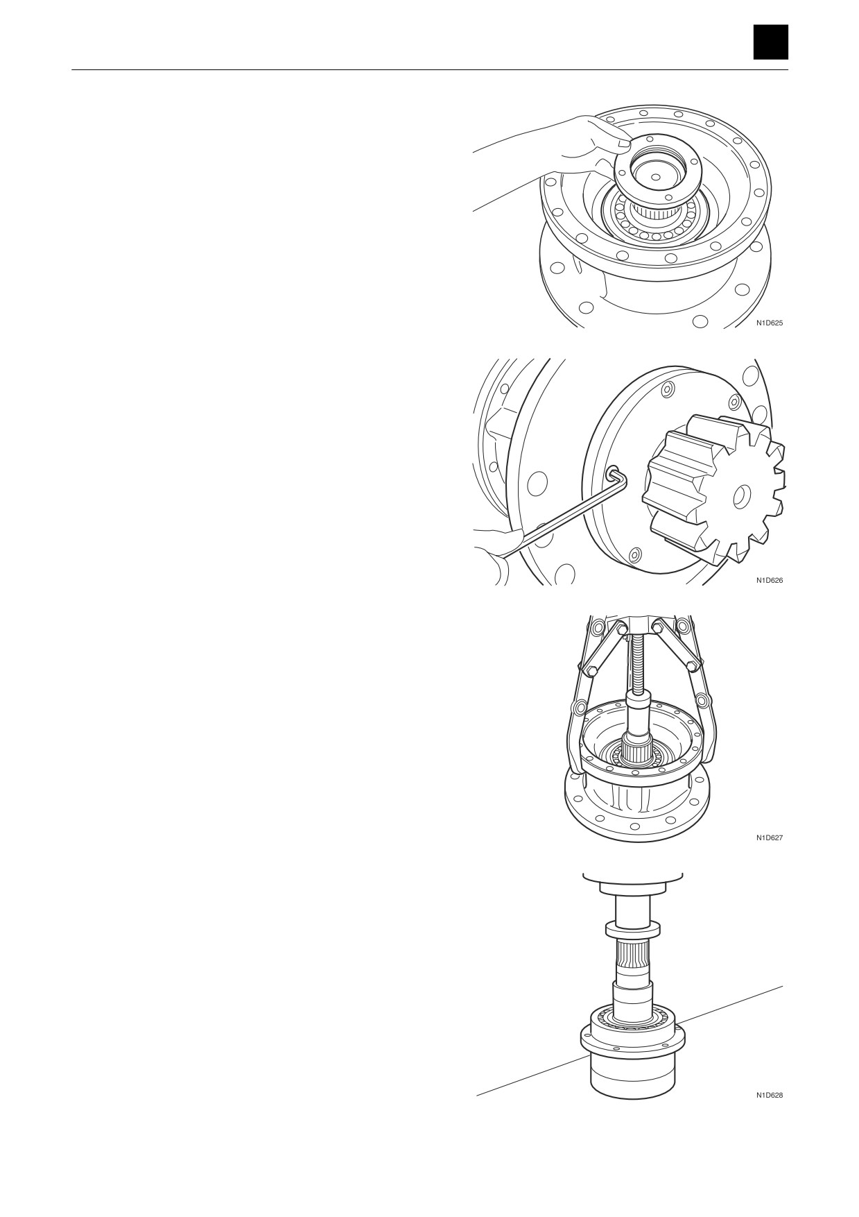
13. Remove the ring nut.
14. Take out the cap screws.
15. Use a puller tool to remove the pinion shaft, bearing,
and cover unit from the case.
16. Remove the bearing and cover unit from the pinion
shaft using the press-fitting jig (D).
14
SLEW MOTOR
4N0AS00
DISASSEMBLY AND ASSEMBLY
SLEW MOTOR 4
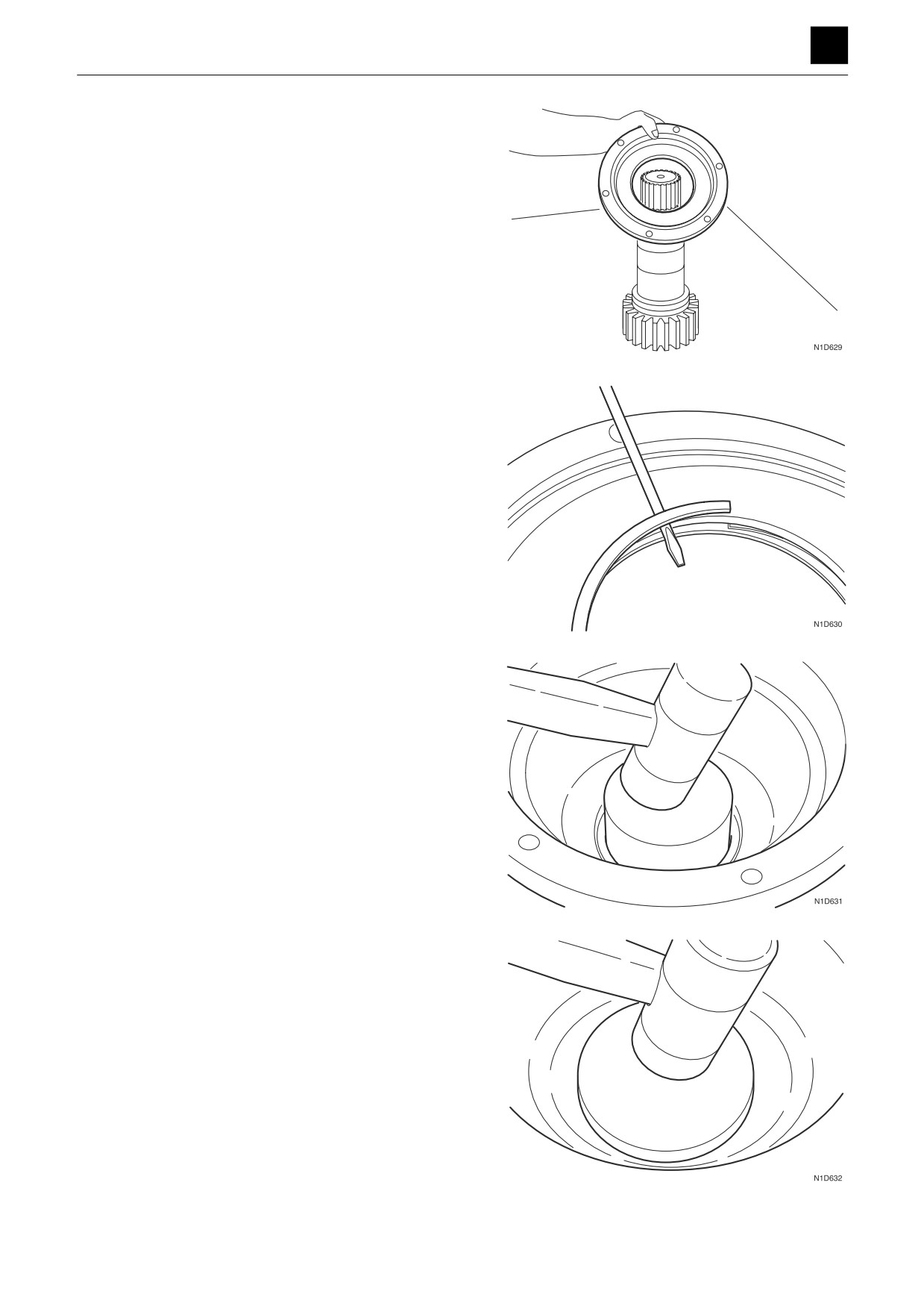
17. Remove the cover.
18. Remove the seal from the cover.
19. Remove the bearing from the case using the press-
fitting jig (E).
20. Remove the oil seal from the case using the press-fit-
ting jig (F).
15
SLEW MOTOR
4N0AS00
DISASSEMBLY AND ASSEMBLY
SLEW MOTOR 4
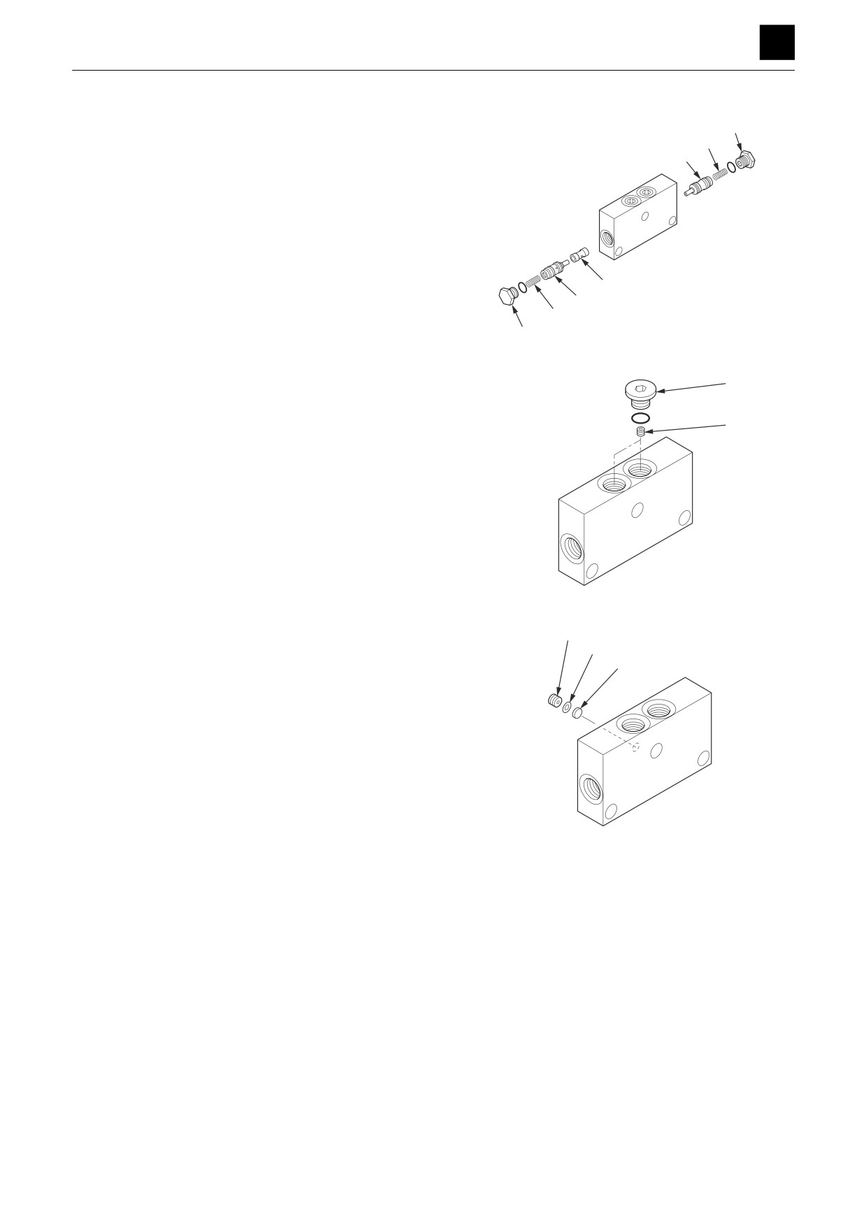
Reversal prevention valve
1. Remove the plug (1) and spring (2).
1
2
2. Remove the check valve assembly (3).
3
3. Remove the sleeve (4).
4
3
2
1
G4D613
5
4. Remove the plug (5) and orifice (6).
6
G4D614
5. Remove the orifice (7), washer (8), and filter (9).
7
8
• Replace the filter whenever the reversal preven-
9
tion valve is disassembled.
G4D615
16
SLEW MOTOR
4N0AS00