Takeuchi compact excavator TB125, TB135, TB145 / diesel TNE / diesel Yanmar. Service Manual - page 60
 

  Index      Manuals     Takeuchi compact excavator TB125 (12510003~), TB135 (13510004~), TB145 (14510004~) / diesel TNE / diesel Yanmar. Service Manual


Search            copyright infringement  


Content      ..     58      59      60      61     ..


Takeuchi compact excavator TB125, TB135, TB145 / diesel TNE / diesel Yanmar. Service Manual - page 60


9.  Starting motror

156

9.2 For 4TNV106 (T)

9.2.1 Specifications

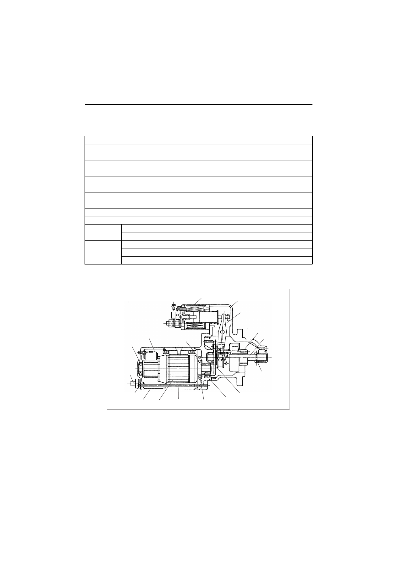
9.2.2 Congiguration drawing

Manufacturer’s model (Hitachi)

-

S13-138

Yanmar code

-

129953-77010

Nominal voltage

V

12

Nominal output

kW

3.0

Rating

Sec

30

Revolution direction (as viewed from pinion)

-

Clockwise

Clutch system

-

Roller clutch

Engagement system

-

Magnetic shift

Pinion: Module/number of teeth

-

M3/9

Weight

kg

7.3

Pinion projection voltage (at 100)

V

8 or less

No-load

Terminal voltage/current

V/A

12/180 or less

Revolution

rpm

3000 or more

Loaded

Terminal voltage/current

V/A

9/500

Torque

N•m (kgf•m)

16.7 (1.7) or more

Revolution

min-1

1270 or more

Magnetic switch

Gear case

Shift lever

Pinion

Gear shaft

Pinion stopper

Needle bearing

Oil seal

Ball bearing

Yoke

Armature

Rear cover

Through bolt

Terminal, E

Ball bearing

Brush

O-ring

9.  Starting motror

157

9.2.3 Troubleshooting

Can the engine be

cranked?

The motor does not stop

even when the key switch is

turned OFF

.

Are the battery charge and

terminal connection normal

without any corrosion?

Is the starting motor

magnetic switch actuating

sound heard?

Is the revolution normal?

Engine does not start.

YES

NO

NO

(slow

 revolution)

NO

YES

Inspect the ignition and

fuel systems.

Inspect the inside of 

the engine.

Inspection

item

Causes and

remedies

Inspect the reduction gear 

(armature, gear shaft) for 

damage and replace if

necessary

.

Inspect pinion

roller clutch for

damage and

replace if necessary

.

٨

Charge or replace the battery

٨

Connect the battery terminal or repair

    corrosion.

٨

Inspect the brush and replace if worn.

٨

If brushes are not worn, replace the

   motor (yoke assy or armature).

    Inspect the starting motor relay wiring

    system and repair if necessary

.

٨

Key switch

٨

Starting motor relay

٨

Connection state

٨

Adjust the dimension.

٨

Inspect the shift lever for deformation,

   the return spring for fatigue and the

   pinion for sliding.

٨

Repair engagement between pinion and

   ring gear or replace as needed.

Replace the engine oil.

Repair or replace the

starting motor

.

Repair or replace the key switch, starting

motor relay or magnetic switch.

Upon abnormality:

   Immediately disconnect the battery negative terminal.

YES

YES

YES

YES

Does the starting motor

revolve?

NO

Does the gear shift

revolve?

Does the starting motor

relay operate?

YES

Are pinion and ring gear

engaging normally?

YES

Are pinion and ring gear

engaging normally?

YES

NO

̪

NO

YES

Are the battery charge

and terminal connection

normal without any

corrosion?

NO

Does the engine run

when the starting motor

is replaced with a

new one?

YES

Is the engine oil

viscosity normal?

NO

NO

٨

Inspect the wiring up to the magnetic

  switch and repair if necessary

.

NO

NO

YES

Does the motor ravolve

when M terminal of

starting motor is connected

to the battery?

NO

9.  Starting motror

158

9.2.4 Component names and disassembly procedure

(1) Disassembly procedure

1)Disconnect the lead.
2)Remove the magnetic switch.
3)Remove the rear cover.
4)Remove the brush holder.
5)Disassemble the gear case and center bracket.
6)Remove the shift lever pin.
7)Remove the gear case dust cover.
8)Remove the pinion.

(2) Disassembly diagram

Ԙ

ԙ

Ԛ

ԛ

Ԝ

ԝ

Ԟ

ԟ

9.  Starting motror

159

9.2.5 Disassembly procedure

(1) Disconnecting the lead

Loosen the M8 nut (12 mm) of the magnetic switch and disconnect the lead.

9.  Starting motror

160

(2) Removal of magnetic switch

Remove the M6 bolts (10 mm × 2).

9.  Starting motror

161

(3) Removal of rear cover

Remove the brush holder tightening screws (4 mmø × 2) and the M5 through bolts (× 2).
Next, disconnect the rear cover from the yoke using a – screwdriver.

9.  Starting motror

162

(4) Removal of brush holder

For the negative (–) brush, bring the brush spring into contact with the side of the brush for lifting from the
commutator surface.
For the positive (+) brush, extract the pull out the brush from the brush holder.
After the brush holder is removed, the armature and yoke can be disassembled.

9.  Starting motror

163

(5) Separating gear case from center bracket

Remove three M6 bolts (10 mm) fastening the gear case to the center bracket.
After removal of the M6 bolts, the center bracket and oil seal can be removed.

9.  Starting motror

164

(6) Removal of shift lever pin

Remove the M6 nut (10 mm) and pull out the shift lever pin.
Now. the dustcover, shift lever, gear case and gear shaft can be removed.

9.  Starting motror

165

(7) Removal of gear case dust cover

Remove the two M5 bolts (using 4 mm hexagon wrench) to disassemble the dust cover from the gear case.

9.  Starting motror

166

(8) Removal of pinion

Slide the pinion stopper towards the pinion and remove the pinion stopper clip using a – screwdriver.

9.  Starting motror

167

9.2.6 Inspection and maintenance

(1) Armature

1)Check the commutator for rough surface. If so, smooth the surface using #500 to #600 emery cloth.

If the outside periphery of the commutator has been deflected over 0.2 mm, repair by a lathe.

2)Measure the depth of the insulating material between commutator segments, and correct if it is less than

0.2 mm.

0.5

0.8 

OO

Undercut

method

9.  Starting motror

168

3)Armature coil continuity and earth tests

Replace if needed

.

Test type

Measurement point

Normal

Abnormal (cause)

Continuity test

Across commutator

Yes

None (open circuit)

Earth test

Between commutator and shaft or armature

None

Yes (short-circuiting)

9.  Starting motror

169

(2) Field coil

1)Field coil continuity and earth tests

Replace if needed

.

Test type

Measurement point

Normal

Abnormal (cause)

Continuity test

Across commutator

Yes

None (open circuit)

Earth test

Between commutator and shaft or armature

None

Yes (short-circuiting)

9.  Starting motror

170

(3) Brush

1)Check wear of the brush and the brush spring force.

New

Used

6

12

Limit

18

2.9 kg

3.5 kg

9.  Starting motror

171

2)Check of brush movement

If the brush does not move smoothly, inspect the brush holder for bending and the brush holder sliding
surface for dirt. Repair or clean as needed.

3)Check the continuity between the insulated brush holder (positive (+)) and the brush holder base (nega-

tive (-)).
If they are electrically continuous, replace since the holder is grounded.


Content      ..     58      59      60      61     ..