Takeuchi compact excavator TB125, TB135, TB145 / diesel TNE / diesel Yanmar. Service Manual - page 58
 

  Index      Manuals     Takeuchi compact excavator TB125 (12510003~), TB135 (13510004~), TB145 (14510004~) / diesel TNE / diesel Yanmar. Service Manual


Search            copyright infringement  


Content      ..     56      57      58      59     ..


Takeuchi compact excavator TB125, TB135, TB145 / diesel TNE / diesel Yanmar. Service Manual - page 58


8. TURBOCHARGER

124

8.3.2 Inspection procedure

(1) Rotor rotation inspection

Inspect the rotor rotation by listening to any abnormal sound generation during rotation.
For inspection with a sound detecting bar, bring the tip end of the bar into strong contact with the turbocharger
case and raise the engine speed gradually.
If any high pitch sound is generated at intervals of 2 to 3 seconds, the rotation is abnormal. Since the bearing
or rotor may be defective in this state, either replace or overhaul the turbocharger.

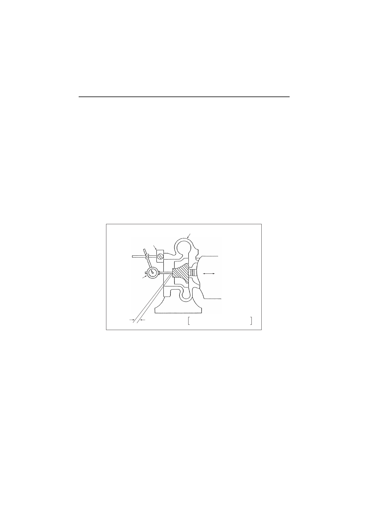
(2) Rotor play inspection

Remove the turbocharger from the engine and inspect the rotor play in the axial and radial directions
according to the procedure below.
After removing the turbocharger from the engine, always bind the oil inlet and outlet holes with adhesive tape.

Rotor play in axial direction

Axial play

Service standard: 0.03 to 0.06 mm
Wear limit           : 0.09 mm

Turbine wheel chamber

Move the turbine shaft
in the axial direction.

Dial gage

Magnet base

8. TURBOCHARGER

125

8.3.3 Waste gate valve adjustment procedure

Rotor play in radial direction

It is indispensable to adjust the waste gate valve opening pressure and lift after its overhaul or inner parts
replacement.
Negligence of this adjustment will adversely affect the engine performance.
[NOTICE]

If the adjustment is impossible, give up overhaul but replace the whole turbocharger assembly.

(1) Method for checking the waste gate valve opening pressure and lift

(a)Equipment

Prepare the equipment shown in the figure below.

Oil inlet

Oil outlet

Service standard: 0.08 to 0.13 mm
Wear limit           : 0.17 mm

Magnet base

Move the turbine shaft in the radial
direction at the same time on the
left and right sides.

Radial play

Dial gage

8. TURBOCHARGER

126

(b)Measuring instruments and devices

(c)Check method

1)Set the manometer control pressure (Pc) applied to the waste gate actuator to 0 and set the dial gage to

the zero point.

2)Gradually open the pressure regulating valve and measure the Pc value when the actuator rod is oper-

ated by 2 mm.

3)For the hysteresis, let the rod move to 3 mm first. The gradually close the pressure regulating valve, mea-

sure the pressure when the rod is moved to 2mm and obtain the difference from the pressure measured in
b. above.

4)Precautions
• Set the dial gage on the extension line of the actuator rod.
• The piping and joints shall completely be free from leak.
• Fix the turbocharger and dial gage securely.
• If an electric manometer is used, it shall have sufficient precision.
• Even when an electric manometer is used, use of a mercury column type manometer in combination is

recommended for calibration and daily check.

• The speed for increasing/decreasing Pc by means of the pressure regulating valve shall be very slow near

the measuring point. If the mm position is exceeded, restart from the beginning.

• Do not apply over 0.49 MPa (5 kgf/cm

2

) to the actuator.

(2) Waste gate actuator leak test

Apply 0.12 Mpa (1.2 kgf/cm

2

) to the actuator and hold the state for minute. The actuator is good if the

pressure then is 0.11 Mpa (1.1 kgf/cm

2

) or above.

Dial gage

Capable of measuring 0 to 10 mm (A flat head type is recommendable.)

Manometer

Mercury column or electrical type (capable of measuring 0 to 1500 mmHg)

Pressure regulating valve

Allowing gradual adjustment in a range between 0 and 2 kgf/cm

2

 (0.196 Mpa)

Pressure reducing valve

Used for suppressing the air supply pressure at 5 kgf/cm

2

 (0.49 Mpa) or less.

Pressure gage

Bourdon tube pressure gage (0 to 10 kgf/cm

2

 (0.98 Mpa))

Manometer

Waste gate actuator

Rod

Dial gage

Waste gate valve

Clip

Hose

Adapter

Pc

Pressure gage

Pressure regulating valve

Pressure reducing valve

(0.49 Mpa)

Compressed air

[Note] Pc (controller pressure) varies with the set
           output in a range between 600 and 750 mmHg.

<5 kg/cm

2

8. TURBOCHARGER

127

8.4 Disassembly procedure

8.4.1 Preparation for disassembly

In addition to the general tools, the following special tools are required for turbocharger disassembly and reas-
sembly:

Tool name

Use

Illustration

Bar

For removing thrust bearing and 
thrust bushing

Material: Copper or brass

Pliers

For removing floating bearing circlip

Pliers

For removing seal ring

Torque driver for TORX bolt
(multifunctional type) 

0.5 to 4.9 N•m (5 to 50 kgf•cm)

For thrust bearing installation 
(for M3) : 1.3 N•m (13 kgf•cm)

For seal plate installation 
(for M3) : 1.3 N•m (13 kgf•cm)

Item sold on market

 (Type: TORX TT20 or equivalent)

Box wrench

For fixing turbine shaft
(mm × dodecagonal)

Box only may be used.

Torque wrench

(single purpose)

For following bolts and nuts:
M8 : mm, kgf•cm (N•m)
M5 : mm, kgf•cm (N•m)

Probe

For measuring play in axial and radial directions: To be installed on a dial 
gage

Ǟ

7.5

(mm)

75

M2.6

P0.45

(0.3149)

To be knurled here

R10

(0.3937)

R5(0.1968)

Ǟ

5(0.1968)

10

15

(0.3937)

(0.5905)

Mount to dial gauge

7(0.2755)

mm (in.)

1(0.0393)

40

(1.5748)

8

8. TURBOCHARGER

128

8.4.2 Inspection before disassembly

1)Inspect the turbine wheel and compressor impeller for any undesirable contact and the rotor for smooth

rotation.

2)Measure the rotor play as described in section 8.3 (2.2).
• Rotor axial play Wear limit:  mm
• Rotor radial play Wear limit : mm

8.4.3 Disassembly

The mounting angles of the turbine housing, bearing housing and compressor housing are determined
according to its mounting state on the engine. Put match marks before starting disassembly.
Note: The number after each part is the one described in the structural drawing in 8.1(2).

(1) Compressor housing removal

1)Remove flanged hexagon bolt 8 and compressor side keep plate 10.
2)Remove compressor housing 7.
Note:
1)Liquid gasket is applied on the surface of compressor housing 7 where bearing housing 15 is mounted.
2)When disassembling compressor housing 7, carefully operate so as not to damage the compressor impel-

ler.

(2) Compressor impeller removal

1)Set a box spanner (10 mm) on the turbine side end of the turbine shaft, and remove shaft end clamp 18.
Note: Pay attention to the loosening direction since the shaft end nut has left-handed screw.
2)Remove compressor impeller 18.

(3) Turbine housing removal

1)Remove hexagon nut 12 and turbine side keep plate 13.
2)Remove turbine housing 11.

(4) Turbine shaft extraction

1)Hold heat insulating plate 20 lightly with a hand, and extract turbine shaft 1.
Note: If the turbine shaft is hard to be extracted, tap the compressor side end of the shaft lightly with a

wooden hammer.

2)Remove heat insulating plate 20.

(5) Seal plate removal

1)Use the Torx driver and loosen M3 Torx T-type machine screw 17 for seal plate mounting.
2)Remove seal plate 4.
Note: Liquid gasket has been applied to the seal plate and bearing housing mounting surface.
3)Remove oil thrower 2 from the seal plate.

(6) Slide bearing and thrust bushing removal

1)Use the Torx driver and loosen the M3 Torx T-type machine screw for thrust bearing installation.
2)Use the bar (copper) and remove thrust bearing 6 and thrust bushing.

8. TURBOCHARGER

129

(7) Floating bearing removal

1)Use the stop ring pliers and remove circlip 16 from bearing housing 15.
2)Remove floating bearing 5 from bearing housing 15.

(8) Seal ring removal

1)Remove turbine side seal ring 3 from turbine shaft 1.
2)Remove compressor side seal ring (small) and compressor side seal ring (large) from oil thrower 2.

8. TURBOCHARGER

130

8.5 Washing and inspection procedure

8.5.1 Washing

(1) Inspection before washing

Visually inspect each part before washing to check trace of seizure, wear, foreign matter or carbon adhesion.
Carefully inspect for identifying the cause of trouble especially when a fault has occurred.

Major inspection items

(2) Washing procedure

Keep the following in mind when washing the parts.

Check point

Checking position

Carbon adhesion state

1)Turbine shaft 1, turbine side seal ring and rear side of turbine wheel
2)Heat insulating plate 20 mounting portion and inside of bearing hous-

ing 15

Lubrication status
(wear, seizure, discoloration, etc.)

1)Turbine shaft 1, journal portion and thrust bushing oil thrower 2
2)Floating bearing 5 and thrust bearing 6
3)Bearing housing 15 and inner wall of bearing fitting ring

Oil leak state

1)Inner wall of turbine housing 11
2)Outer surface of bearing housing 11 and heat insulating plate 20

mounting portion

3)Turbine shaft 1 turbine side seal ring portion and rear side of turbine

wheel

4)Inner wall of compressor housing 7
5)Rear side of compressor impeller 18
6)Surface and seal ring inserting portion of seal plate 4

Part

Tools and detergent

Procedure

a)Turbine s haft •Tools

1)Bucket (500 × 500)
2)Heat source:

Steam or gas burner

3)Brush
•Detergent
Standard carbon
removing agent

1)Boil the turbine in the washing bucket. 

Do not strike the blade to remove the carbon.

2)Immerse in the detergent until the carbon and other

deposits are softened.

3)Use a plastic scraper or hand hair scrubber to remove

the softened deposits.

4)Protect the bearing surface and seal ring groove on

the turbine shaft so as not to be damaged.

5)Any deposit remaining on the turbine shaft due to

improper washing may cause unbalancing. Be sure to
remove thoroughly. Never use a wire brush.

b)Turbine wheel 

chamber

•Tools
Same as for turbine shaft

•Detergent
Same as for turbine shaft

1)Boil the turbine in the washing bucket.
2)Immerse in the detergent until the carbon and other

deposits are softened.

3)Use a plastic scraper or hard hair scrubber to remove

the softened deposits.

c)Blower blade 

and chamber

•Tools
1)Bucket (500 × 500)
2)Brush

•Detergent

1)Immerse in the washing bucket until the deposit is

softened.

2)Use a plastic scraper or hard hair scrubber to remove

the softened deposits. 
Never use a wire brush.

d)Others

1)Wash all other parts with diesel oil.
2)Clean the lubricating oil path by blowing with compressed air.
3)Be especially careful so as not to damage or corrode the parts.

8. TURBOCHARGER

131

8.5.2 Inspection procedure

(1) Compressor housing 7

Inspect the compressor housing for any contact trace
with the compressor impeller, surface defect, dent or
crack at joint surface, and replace it if defective.

(2) Turbine housing 11

Inspect any trace of contact with the turbine wheel,
exfoliation due to degradation by oxidation of the cast
surface, thermal deformation or crack.
Replace with a new one of defective.

(3) Compressor impeller 18

Inspect any contact trace, chipping, corrosion or
deformation.
Replace with a new one if defective.

(4) Turbine shaft 1

1)Inspect any contact trace, chipping, thermal discolor-

ation or deformation at the turbine wheel. Check the
shaft portion for bend, the journal portion for thermal
discoloration or abnormal wear, and the seal ring
groove for surface defect or wear. Replace with a
new one if defective.

2)Measure the turbine shaft journal outside diameter

(A) and seal ring groove width (E).
Replace with a new turbine shaft if beyond the wear
limit.

Wear limit of journal outside diameter (A)

RHF5 



 7.98 mm

RHB51 



 7.98 mm

RHB31 



 6.25 mm

Wear limit of ring groove width (E)

RHF5 



 1.29 mm

RHB51 



 1.29 mm

RHB31 



 1.07 mm

3)Measure the turbine shaft run-out, and replace with

a new turbine shaft if it exceeds 0.011 mm.

(5) Heat insulating plate 20

Inspect the heat insulating plate for any contact trace,
thermal deformation or corrosion Replace with a new
one if defective.

E

A

V block

8. TURBOCHARGER

132

(6) Thrust bushing, oil thrower 2 and thrust 

bearing 6 Inspect each part for wear, sur-
face defect and discoloration.

Replace with a new one if defective even within the wear
limit.

(a)Thrust bushing

Measure the distance between grooves (K) of the thrust
bushing, and replace with a new one if the wear limit is
exceeded.

Wear limit

RHF5 



 4.07 mm

RHB51 



 4.07 mm

RHB31 



 3.65 mm

(b)Oil thrower 2

Measure the seal ring groove widths (G1) and (G2), and replace with a new one if the wear limit is exceeded.

Wear limits

RHF5--- G1: 1.31 mm, G2: 1.11 mm
RHB51--- G1: 1.31 mm, G2: 1.11 mm
RHB31--- G1: 1.04 mm, G2: 0.84 mm

(c)Thrust bearing 6

Measure the thrust bearing width (J), and replace with 
a new one if the wear limit is exceeded.

Wear limit

RHF5 



 3.98 mm

RHB51 



 3.98 mm

RHB31 



 3.58 mm

(7) Floating bearing 5

1)Inspect the floating bearing for abnormal wear, 

discoloration or surface defect.
Replace with a new one if defective.

2)Measure the inside diameter (C) and outside diameter (D).

Replace the bearing if either wear limit is exceeded.

Wear limits

RHF5 



 Outside diameter (D): 12.31 mm, 

Inside diameter (C): 8.04 mm

RHB51 



 Outside diameter (D): 12.31 mm, 

Inside diameter (C): 8.04 mm

RHB31 



 Outside diameter (D): 9.93 mm, 

Inside diameter (C): 6.29 mm

Thrust bushing

Oil throwe

G1

K

G2

8. TURBOCHARGER

133

(8) Bearing housing 15

1)Inspect the housing for cast surface exfoliation due

to oxidation and degradation, dent or crack.

2)Inspect circlip 16 for chipping or crack, and replace

with a new one if defective.

3)Measure the (B) and (F) portions of the bearing

housing shown in the figure below.
Replace with a new one if either wear limit is
exceeded.

Wear limit of bearing housing inside diameter (B)

RHF5 



 12.42 mm

RHB51 



 12.42 mm

RHB31 



 10.01 mm

Wear limit of turbine side seal ring inserting 
portion (F)

RHF5 



 15.05 mm

RHB51 



 15.05 mm

RHB31 



 11.03 mm

(9) Seal plate 4

1)Inspect the seal plate for any contact trace, joint sur-

face defect, dent or crack.
Replace it if defective.

2)Measure the seal ring inserting dimensions (H1 and

H2) on the compressor side, and replace the seal
ring with a new one if either wear limit is exceeded.

Wear limits

RHF5 



 H1: 12.45 mm, H2: 10.05 mm

RHB51 



 H1: 12.45 mm, H2: 10.05 mm

RHB31 



 H1: 10.04 mm, H2: 8.01 mm

(10)Seal rings

Replace seal rings with new ones.

(11)Inspect keep plates 10, 13 and bolts for

any deformation, and replace defective
parts with new ones. Also replace M3 Torx
machine screws with new ones.

Turbine side

Bearing fitting ring

F

Inner plate

Compresser
side

H2

H1

8. TURBOCHARGER

134

8.6 Reassembly procedure

8.6.1 Preparation for reassembly

1)Prepare general tools, special tools, liquid gasket

(Three Bond No.1207) and Locktite No.242 before
reassembling the turbocharger.

2)Always replace the following parts with new ones:
• Turbine side seal ring   1pc.
• Compressor side seal ring (large)   1pc.
• Compressor side seal ring (small)   1pc.
• M3 machine screws   3pcs.
• M3 machine screws   4pcs.

8.6.2 Reassembly

(1) Floating bearing installation

1)Use the snap ring pliers and install inner circlip 16 on

bearing housing 15.

2)Install floating bearing 5 in bearing housing 15.
3)Use the snap ring pliers and install outer circlip 16 on

bearing housing 15.

Note:
1)The circlip joint shall be positioned as shown in the

figure at right above. 

The rounded side of the circlip shall face the
bearing.

2)Apply lubricating oil on the floating bearing before

reassembly.

(2) Turbine shaft installation

1)Fit the seal ring onto turbine shaft 1.
2)Install heat insulating plate 20 on the turbine side of

bearing housing 15.

3)Apply lubricating oil on the journal portion of the tur-

bine shaft and insert the shaft from the turbine side
of bearing housing 15.

Note: Carefully operate so as not to damage the floating

bearing by the turbine shaft. 
The seal ring joint shall be positioned on the
lubricating oil inlet side after centering with the
turbine shaft.

Circlip

Floating metal

Match up contact surface

V

iew from the turbine

Lubricating oil inlet

For all other than above

Lubricating oil inlet

Applicable only to the one
closest to the turbine

8. TURBOCHARGER

135

(3) Thrust bearing installation

1)Fit thrust bushing on turbine shaft 1.
2)Apply lubricating oil on the bearing portion of thrust

bearing 6 and install it in bearing housing 15.

3)Apply Locktite on the threaded portion of M3 Torx T

machine screw 17 for thrust bearing installation, and
use Torx torque driver for installation by tightening to
the specified torque.
Tightening torque: 1.3 ± 0.1 N•m (13 ± 1 kgf•cm)

(4) Seal plate installation

1)Fit the seal ring on oil thrower 2.
2)Insert oil thrower 2 into seal plate 4.
Note: The seal ring joint portion shall be positioned as 

illustrated at right.

3)Apply liquid gasket (Three Bond No.1207) on the

seal plate mounting surface on the compressor side
of bearing housing 15.

Note: See the illustration below for the applying 

position.

Applying thickness: 0.1 to 0.2 mm

4)Install seal plate 4 on bearing housing 15.
5)Apply Locktite on the threaded portion of M3

machine screw for seal plate mounting, and tighten it
with a torque screwdriver.
Tightening torque: 1.3 ± 0.1 N•m (131 kgf•cm)

L.O. inlet

View from the compressor

45

q

Liquid gasket
applying position

Carefully prevent the liquid
gasket from leaking out to
this area

8. TURBOCHARGER

136

(5) Compressor impeller installation

1)Fit compressor impeller 18 onto turbine shaft 1.
2)Set a box spanner (10 mm) on the turbine side end

of turbine shaft 1, and tighten shaft end nut 19.

Note: Since the shaft end nut has left-handed screw, 

pay attention to the tightening direction.

Tightening torque: 2.0 ± 0.2 N•m (20 ± 2 kgf•cm)

(6) Turbine housing installation

1)Install bearing housing 15 on turbine housing 11 by

aligning the match marks put before disassembly.

Note: In case of part replacement, check the oil inlet 

and outlet positions and the exhaust gas inlet 
position before reassembly.

2)Install the turbine side keep plate and tighten M8

hexagon bolt 12.
Tightening torque: 285 ± 10 N•m (28 ± 1 kgf•cm)

(7) Compressor housing installation

1)Apply liquid gasket (Three Bond No.1207) on the

compressor side flange of bearing housing 15.

Note: See section (4)3) for the portion to be applied.

Applying thickness: 0.1 to 0.2 mm

2)Check the mark and install the compressor housing

7 on the bearing housing 15.

Note: When a part is replaced, confirm a position of an 

oil entrance and a position of an air exit, and 
assemble it.

3)Install the keep plate 10 on compressor side, and

tighten M8 hexagon bolt 8.
Tightening torque: 48 N•m (4.7 ± 0.5 kgf•cm)

(8) Rotor play measurement

See the inspection procedure in section 8.3.2 for the
measurement method.
If the rotor play does not satisfy the standard,
reassembly is necessary since assembly error or use of
a wrong part is conceivable.

Service standard of rotor play in axial direction

RHF5 



 0.03 to 0.06 mm

RHB51 



 0.03 to 0.06 mm

RHB31 



 0.022 to 0.053 mm

Service standard of rotor play in radial direction

RHF5 



 0.08 to 0.13 mm

RHB51 



 0.08 to 0.13mm

RHB31 



 0.061 to 0.093mm

8. TURBOCHARGER

137

8.7 Handling after disassembly and reassembly

When installing the turbocharger on the engine or handling the turbocharger after installation, strictly observe
the instructions given below.
Especially pay careful attention for preventing foreign matter entrance into the turbocharger.

8.7.1 Instructions for turbocharger installation

Lubrication system

1)Pour new lubricating oil through the oil filler port before installation on the engine, and manually turn the

turbine shaft to lubricate the floating and thrust bearings.

2)Flush the oil inlet pipe from the engine and outlet pipe, and check no crushed pipe nor dirt or foreign mat-

ter remaining in the pipes.

3)Connect the pipes securely so as to ensure no oil leak from joints.

Intake system

1)Check no foreign matter or dirt in the intake line.
2)Connect securely to prevent any air leak from joints with the intake duct and air cleaner.

Exhaust system

1)Check no dirt or foreign matter in the exhaust system.
2)Since heat resistant steel is used for the bolts and nuts, do not use general bolts and nuts for installation.

Always apply anti-seizure agent on fastening bolts and nuts to be tightened.
(Use heat-resistant hexagon bolts for the turbine housing.)

3)Connect exhaust pipes securely to prevent gas leak from each pipe joint.

8. TURBOCHARGER

138

8.8 Troubleshooting

Sufficient turbocharger performance and required engine output cannot be obtained if there is any fault. In
such a case, first check each engine part to see there is no engine fault. Then inspect the turbocharger for
troubleshooting according to the procedure shown below.

8.8.1 Excessively exhaust smoke

(1) Insufficient intake air volume

(2) Turbocharger revolution failure

(3) Influence of exhaust resistance

8.8.2 White smoke generation

Cause

Corrective action

1)Clogged air cleaner element
2)Blocked air intake port
3)Leak from a joint in intake line

•Replace or wash the element.
•Correct to the normal state.
•Inspect and repair.

Cause

Corrective action

1)Deposit of impurities in oil sticking on the turbine

side seal portion to make turbine revolution heavy

2)Sticking bearing
•Insufficient lubrication or clogged lubrication piping
•Excessively high oil temperature
•Unbalanced rotating part
•Insufficient warming up or sudden stoop from loaded

operation (no-load operation)

3)Contact or breakdown of turbine wheel or blower

vane

•Excessive revolution
•Excessive exhaust temperature rise
•Foreign matter invasion
•worn bearing
•Assembly defect

•Turbocharger overhaul (disassembly and washing)

with lubricating oil replacement

•Turbocharger overhaul (disassembly and repair)
•Lubricating oil line inspection, repair of defective

portion and lubricating oil replacement

•Rotating part replacement or washing
•Strict observance of instructions in operation man-

ual

•Inspection and repair of each engine part
•Perfect foreign matter elimination in disassembled

state, followed by inspection and repair of individual
air cleaner and engine components

•Turbocharger overhaul (disassembly and repair)
•Reassembly

Cause

Corrective action

1)Exhaust gas leak before the turbocharger to

decrease its revolutions

2)Deformed or clogged exhaust pipe to decrease tur-

bocharger revolutions

•Joint inspection and correction

•Correct to the normal state.

Cause

Corrective action

1)Clogged or deformed oil return pipe causing oil flow

to the blower or turbine side

2)Excessive bearing wear causing abnormal wear or

damage of seal ring

•Repair or pipe replacement

•Turbocharger disassembly and repair

8. TURBOCHARGER

139

8.8.3 Sudden oil decrease

8.8.4 Decrease in output

8.8.5 Poor (slow) response (starting) of turbocharger

8.8.6 Abnormal sound or vibration

(1) Abnormal sound generation

(2) Vibration

Cause

Corrective action

1)Excessive bearing wear causing abnormal wear or

damage of seal ring

•Turbocharger disassembly and repair

Cause

Corrective action

1) Gas leak from any part in exhaust piping
2)Air leak from discharge side of blower
3)Clogged air cleaner element
4)Fouled or damaged turbocharger

•Inspection and repair of defective portion

•Element cleaning or replacement
•Turbocharger disassembly and repair or replace-

ment

Cause

Corrective action

1)Hard carbon deposit on the turbine side (wheel seal-

ing portion) to make turbine shaft revolution heavy

2)Incomplete combustion

•Turbocharger disassembly and washing with lubri-

cating oil replacement

•Engine combustion state inspection, followed by

improvement of combustion to normal state

Cause

Corrective action

1)Excessively narrowed gas path due to clogged noz-

zle in turbine wheel chamber or reverse flow of
blower discharge in acceleration (generally called
surging)

2)Contact rotating part

•Turbocharger disassembly and washing

•Turbocharger disassembly and repair or replace-

ment

Cause

Corrective action

1)Loosened intake, exhaust or oil pipe connection with

the turbocharger

2) Damaged bearing, contact between rotating part and

adjacent part, or chipping of turbine wheel or blower
vane due to foreign matter in version

3) Unbalanced rotating part

•Turbocharger installation status check and repair of

defective portion

•Turbocharger disassembly with repair or replace-

ment, or perfect removal of foreign matters in case
of foreign matter invasion

•Repair or replacement of rotating part


Content      ..     56      57      58      59     ..