Takeuchi compact excavator TB125, TB135, TB145 / diesel TNE / diesel Yanmar. Service Manual - page 59
 

  Index      Manuals     Takeuchi compact excavator TB125 (12510003~), TB135 (13510004~), TB145 (14510004~) / diesel TNE / diesel Yanmar. Service Manual


Search            copyright infringement  


Content      ..     57      58      59      60     ..


Takeuchi compact excavator TB125, TB135, TB145 / diesel TNE / diesel Yanmar. Service Manual - page 59


9.  Starting motror

140

9. Starting motror

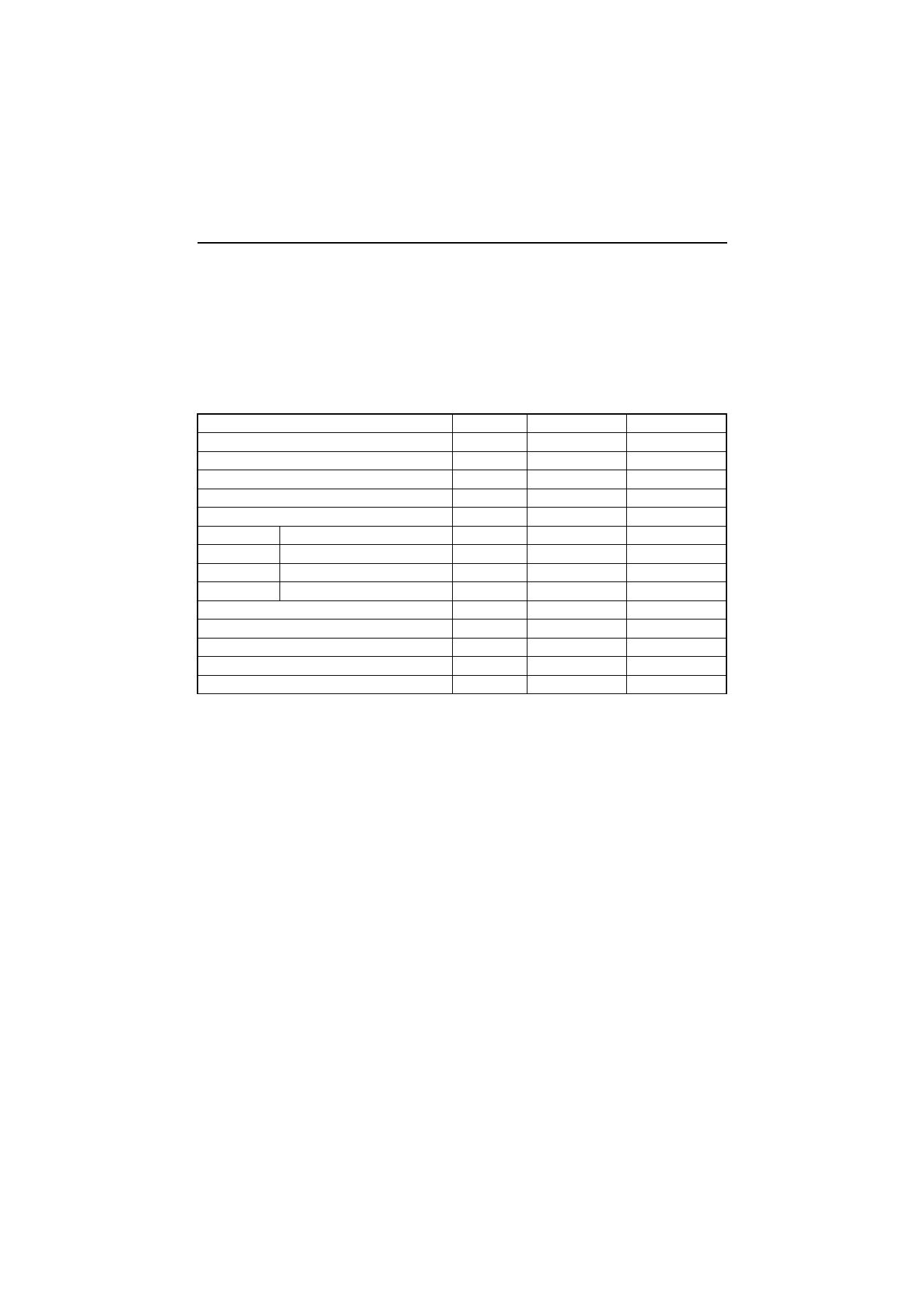
As a representative example of starter, the one for 4TNV94L98 and 4TNV106 (T) is shown in this chapter.

9.1 For 4TNV94L/ 98

9.1.1 Specifications

Manufacturer’s model (Hitachi)

-

S13-204

S13-205

Yanmar code

-

129900-77010

129900-77020

Nominal output

kW

2.3

Weight

kg

5.5

Revolution direction (as viewed from pinion)

-

Clockwise

Engagement system

-

Magnetic shift

No-load

Terminal voltage/current

V/A

11/140 or less

Revolution

rpm

4100 or above

Loaded

Terminal voltage/current

V/A

2.5/1050 or less

Torque

N•m (kgf•m) 24.5 (2.5) or above

Clutch system

-

Overrunning

Pinion projection voltage (at 100 °C)

V

8.6 or less

Pinion DP or module/number of teeth

-

M3/9

difference (O-ring, oil seal)

-

Dry (none)

Wet (with)

Application

-

Standard

Option

9.  Starting motror

141

9.1.2 Components

Magnetic switch

Shift lever

Gear case

Oil seal

Pinion shaft

Bearing retaine

r

O-ring

Clutch Assy

Through bolt

Rear cover

Armature

Field coil

Brush

9.  Starting motror

142

9.1.3 Troubleshooting

Is the shift lever at

the neutral position?

Can the engine be

cranked?

The motor does not stop

even when the key switch is

turned OFF

.

Are the battery charge and

terminal connection normal

without any corrosion?

Is the revolution normal?

Engine starting failure?

YES

NO

NO

YES

NO

(slow revolution)

NO

YES

Inspect the fuel systems

Inspect the inside of 

the engine.

Set the shift lever at

the neutral position

Inspection

item

Causes and

remedies

Pinion roller clutch damage,

inspection and replacement

Reduction gear damage,

inspection and replacement

٨

Charge or replace the battery

٨

Connect the battery terminal and

    repair corrosion.

٨

Inspect the brush and replace if worn.

٨

If brushes are not worn, replace the

   motor (yoke assy or armature).

    Inspect the wiring up to the magnetic

    switch and repair if necessary

.

٨

Key switch

٨

Safety relay

٨

Magnetic switch

٨

Connection state

٨

Adjust / dimension.

٨

Inspect the shift lever for deformation,

   the return spring for fatigue and the

   pinion for sliding.

٨

Repair meshing between pinion and

   ring gear or replace as needed..

Replace the Lube oil.

Repair or replace the

starting motor

.

Magnetic switch con-

tact defect.  Replace it.

Repair or replace the key switch, starting

motor relay or magnetic switch.

For an abnormality (Immediately disconnect the

battery negative terminal.)

ψ

When the starting motor is wetted with water

,

      always replace the magnetic switch even if the

      function is normal.

YES

YES

Is the starting motor

sound heard?

YES

Pinion and ring gear

meshing normal?

YES

NO

̪

NO

YES

Are the battery charge

and terminal connection

normal without any

corrosion?

Slow revolution

Does the engine run

when the starting motor

is replaced with a

new one?

YES

Is the Lube oil

viscosity normal?

NO

Is the starting motor

magnetic switch actuating

sound head?

NO

YES

Connect the M terminal of

the individual starting motor

with the battery

.  Does the

motor run?

NO

YES

NO

9.  Starting motror

143

9.1.4 Names of parts and disassembly procedure

(1) Disassembling order

1)Nut M8 (Disconnect the connecting wire.) 



 See the disassembly drawing.

2)Screw M4 (2)
3)Through bolt M5 (2)
4)Rear cover
5)Brush holder
6)Yoke assy.
7)Armature
8)Bolt M6 (2)
9)Magnetic switch

10)Dust cover
11)Shift lever
12)Screw M4 (3)
13)Bearing retainer
14)Gear case
15)Pinion stopper clip
16)Pinion stopper
17)Return spring
18)Pinion shaft
19)Clutch assy.

Disassembly drawing

1

2

3

4

5

6

7

8

9

10

11

12

13

14

15

16

17

18

19

9.  Starting motror

144

(2) Disassembly procedure

1)Nut M8

Remove the magnetic switch nut M8 (12 mm), and
disconnect the connecting wire.

2)Screw M4 (2)

3)Through bolt M5 (2)

4)Rear cover

Remove the M4 screw fastening the brush holder
and remove through bolt M5 for rear cover removal.

5)Brush holder

Pull the brush spring up with the brush spring puller.
On the negative (-) side, bring the brush spring into
contact with the side of the brush for lifting from the
commutator surface. On the positive (+) side, extract
the brush from the brush holder.

Connecting wire

Fig. 1

1

2

3

4

Fig. 2

Fig. 3

9.  Starting motror

145

6)Yoke Assy.

7)Armature

Remove the brush holder. The armature and yoke
assy can now be removed.

8)Bolt M6 (2)

9)Magnetic switch

Remove bolt M6 (10 mm), and the magnetic switch
can be removed.

10)Dust cover

11)Shift lever

Take the dust cover out from the gear case. The shift
lever can be removed.

5

6

7

Fig. 4

8

9

Fig. 5

10

11

Fig. 6

9.  Starting motror

146

12)Screw M4 (3)

13)Bearing retainer

14)Gear case

Remove screw M4, and the bearing retainer and
clutch assy can be removed.

15)Pinion stopper clip

Remove the bearing retainer at the edge and the
bearing, and shift the pinion stopper toward the pin-
ion. Use a plain screwdriver and pry to remove the
pinion stopper clip.

16)Pinion stopper

17)Return spring

18)Pinion shaft

19)Clutch Assy

Remove the pinion stopper clip. The pinion stopper,
return spring, pinion shaft and bearing retainer can
be removed.

Disassembly is completed now.

12

13

14

19

Fig. 7

15

Pinion stopper clip

Plain
straight-edge
screwdriver

(

)

Fig. 8

13

15 16 17

18

19

Fig. 9

9.  Starting motror

147

9.1.5 Inspection and maintenance

(1) Armature

(a)Commutator outside diameter

Measure the commutator outside diameter and replace
the commutator if the measured value is less than the
limit.

(b)

Armature coil continuity test

Check continuity between commutator segments with a
multimeter. Good if continuity exists.

In case of no continuity (coil disconnection), replace the
armature.

(c)

Armature coil insulation test

Inspect the continuity between a commutator segment
and the shaft or core with a multimeter. Good if no
continuity exists.

If continuity exists (coil short circuit), replace the
armature.

mm

Standard

Limit

36.5

35.5

Fig. 10

Multimeter

Fig. 11

Multimeter

Fig. 12

9.  Starting motror

148

(d)Armature and commutator run-out

Use a dial gage and measure the armature core run-out
and commutator run-out. Correct or replace if the limit is
exceeded.

(e)

Commutator surface inspection

If the commutator surface is roughened, grind with #500
to #600 emery cloth.

(f)

Commutator insulation depth

Measure the depth of the insulating material between
commutator segments, and correct it if it is less than the
limit.

mm

Standard

Limit

Armature

0.03

0.2

Commutator

0.03

0.2

mm

Standard

Limit

0.5 to 0.8

0.2

Commutator

Armature

Fig. 13

Fig. 14

Hack-saw

Commutator

Commutator

0.5

0.8mm

Commutator

segment

Insulating

material

Abnormal

Normal

Fig. 15

9.  Starting motror

149

(2) Field coil

(a)

Field coil continuity test

Check continuity between field coil terminals. Good if
continuity exists.

If no continuity (coil disconnection), replace the field coil.

(b)

Field coil insulation test

Check continuity between field coil terminal and yoke.
Good if no continuity exists.

If continuity exists (coil short circuit), replace the
armature.

(3) Brush

Measure the length of the brush. Replace with a good
one if the length is less than the limit.

mm

Standard

Limit

15

9

Multimeter

Fig. 16

Multimeter

Fig. 17

Brush

Fig. 18

9.  Starting motror

150

(4) Brush holder

(a)

Brush holder insulation test

Check the continuity between the brush holder (+ side)
and base (- side) with a multimeter. Good if no continuity
exists.

If continuity exists (insulation defect), replace the brush
holder.

(b)

Brush spring inspection

Inspect the brush spring pressure.

(5) Magnetic switch

When the starting motor is wetted with water, always
replace the magnetic switch with a new even if the
function is normal.

(a)Shunt coil continuity test

Check the continuity between the S terminal and the
switch body. Good if continuity exists.

If no continuity (coil disconnection), replace the 
magnetic switch.

N (kgf)

Standard spring force

31 to 39 (3.1 to 3.9)

Multimeter

Fig. 19

Fig. 20

Multimeter

Fig. 21

9.  Starting motror

151

(b)Series coil continuity test

Check continuity between the S and M terminals. 
Good if continuity exists.

If no continuity (coil disconnection), replace the 
magnetic switch.

(c)

Contact continuity test

Depress the magnetic switch with the plunger at the
bottom. Check continuity between the B and M terminals
with a multimeter. Good if continuity exists.

If no continuity (coil continuity defect), replace the
magnetic switch.

(6) Pinion clutch

(a)Pinion inspection

Manually rotate the pinion. Inspect if it is rotated
smoothly in the driving direction, and is locked in the
opposite direction. Replace the pinion clutch if abnormal.

Multimeter

Fig. 22

Multimeter

Fig. 23

Fig. 24

9.  Starting motror

152

(b)Pinion sliding inspection

Check if the pinion slide smoothly in the axial direction.
If damaged, rusted or heavy in sliding, repair it.
If grease is applied too much on the pinion shaft, sliding
becomes heavy.

(c)

Ball bearing inspection

Rotate the ball bearing while holding the outer race with
fingertips. Inspect if it is sticking or it there is play.

9.1.6 Service standards

Brush

Spring force

N (kgf)

35 (3.6)

Standard height/wear limit

mm

15/9

Magnetic switch resistance, series coil/shunt coil (at 20°C)

0.27/0.60 

Commutator

Standard diameter/limit diameter

mm

36.5/35.5

Difference between maximum 
and minimum diameter

Repair limit/repair accuracy

mm

0.2/0.03

Mica undercut depth chips

Repair limit/repair accuracy

mm

0.2/0.5 to 0.8

Bearing type

Armature fount

Nominal number

-

6903DDU

Armature rear

-

608DDU

Pinion front

-

60004DDU

Pinion rear

-

6904DDU

L dimension (pinion projection length)

mm

0.3-1.5

Fig. 25

Fig. 26

9.  Starting motror

153

9.1.7 Assembly

The assembly procedure is the reverse of the 
disassembly procedure, but pay attention to the 
following points:

(1) Grease application points

• Gears in the gear case
• Shift lever operating portion
• Pinion sliding portion
• Magnetic switch plunger sliding portion

Use the specified grease as below table at all points.

(2) Magnetic switch assembly

1)Install the shift lever on the magnetic switch with the

torsion spring in-between.

2)For installation on the gear case, install the magnetic

switch with the shift lever on the gear case after pull-
ing the pinion out. Fix the magnetic switch by tight-
ening a built-in bolt M6. Do not forget to install the
dust cover (adjusting shim).

Pinion and magnetic switch plunger sliding portions

NPCFG-6A

Gears

MALTEMP SRL

Shift lever operating portion

ALBANIA No.1

Fig. 27

Fig. 28

9.  Starting motror

154

(3) Pinion projection length

Connect the positive (+) lead from the battery to terminal
S and negative (-) lead to terminal M. Turn the switch
ON and measure the pinion moving distance L in the
thrust direction.
Perform this test within 10 seconds.

Note: Before measuring the dimension, pull the 

pinion out lightly in the direction of the arrow.

If the measured L dimension is outside the standard
range, either insert or remove the dust cover (adjusting
shim 0.5 mm, 0.8 mm) for adjustment.

mm

Standard

L

0.31.5

0.3

1.5mm

S

M

l

Fig. 29

Dust  cover
(adjusting shim:
 0.5mm, 0.8mm)

Fig. 30

9.  Starting motror

155

9.1.8 Characteristic test

Since the characteristics can be checked roughly by means of a simple no-load test as explained below.
NOTE: Complete the test quickly since the rating of the starting motor is 30 seconds.

(1) No-load test

Fix the starting motor on a test bench and connect wiring as shown in Fig.31. When the switch is closed, a
current flows in the starting motor, which is rotated at no-load. Measure the current, voltage and number of
revolutions then and check if they satisfy the specified characteristics.

Ammeter

Voltmeter

Battery

S

B

E

SW

Fig. 31


Content      ..     57      58      59      60     ..