Takeuchi compact excavator TB125, TB135, TB145 / diesel TNE / diesel Yanmar. Service Manual - page 57
 

  Index      Manuals     Takeuchi compact excavator TB125 (12510003~), TB135 (13510004~), TB145 (14510004~) / diesel TNE / diesel Yanmar. Service Manual


Search            copyright infringement  


Content      ..     55      56      57      58     ..


Takeuchi compact excavator TB125, TB135, TB145 / diesel TNE / diesel Yanmar. Service Manual - page 57


5.  Lubrication System

109-2

Point 2

[Disassemble-Reassemble]
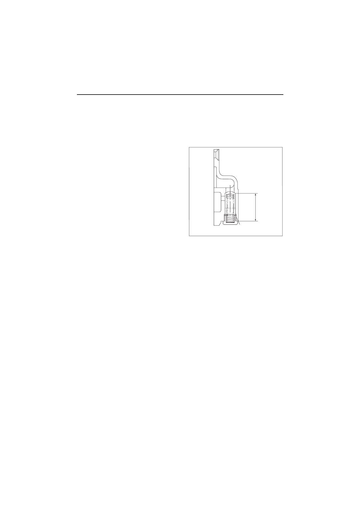
• Only wash the pressure regulating valve. Disassembly is unnecessary unless any abnormality in operation

is detected.

• Lube oil pressure

Refer to the table of 12.1 in chapter 12 for lube oil pressure.

• Structure of pressure regulating valve

(R.1)

M14

˜

1.5

33

(3TNV82A

4TNV88)

5.  Lubrication System

110

5.5 Parts Inspection and measurement

5.5.1 Trochoid pump inspection and measurement

(1) Outside clearance and side clearance of

outer rotor

Insert a gap gage between a outer rotor and a pump
body, and measure the clearance.

(2) Tip clearance between outer rotor and 

inner rotor

Insert a gap gage between an outer rotor and an inner

rotor, and measure the tip clearance.

(3) Side clearance of outer rotor

When measuring a side clearance, put a right-angle gage to the pump body, insert a gap gage and measure
the clearance.

(R.1)

Outside clearance

mm

Model

Standard

Limit

3TNV82A to 88

0.12 to 0.21

0.30

4TNV94L/98

0.100 to 0.155

0.25

4TNV106(T)

0.100 to 0.165

0.25

Tip clearance                         mm

Standard

Limit

-

0.16

Side clearance

mm

Model

Standard

Limit

3TNV82A to 88

0.02 to 0.07

0.12

4TNV94L/98

0.05 to 0.10

0.15

4TNV106(T)

0.03 to 0.12

0.17

Outer diameter clearance

Outer rotor

Gear case

Side clearance

5.  Lubrication System

111-1

(4) Inner rotor and gear boss clearance (3TNV82A-4TNV88)

(5) Rotor shaft clearance (4TNV94L/98/106)

Measure the outside diameter of rotor shaft and the shaft
hole diameter of gear case. Calculate the clearance from
that difference.

Item

Part

Standard 

dimension

(mm)

Standard

clearance

(mm)

Standard

clearance limit

(mm)

Inside clearance
of inner rotor

Gear boss diameter

53.05 to 53.15

0.3 to 0.5

0.6

Rotor inner diameter

53.45 to 53.55

Width across flat
clearance of inner rotor

Width across flat of gear boss

49.45 to 49.75

0.2 to 0.6

0.7

Width across flat of rotor

49.95 to 50.05

mm

Model

Inspection item

Standard

Limit

4TNV94L/98

Gear case bearing I.D.

12.980 to 13.020

13.05

Rotor shaft O.D.

12.955 to 12.970

12.945

Rotor clearance

0.035 to 0.065

0.105

4TNV106(T)

Gear case bearing I.D.

13.000 to 13.020

13.05

Rotor shaft O.D.

12.955 to 12.965

12.945

Rotor clearance

0.035 to 0.065

0.105

Rotor inner

diameter

Crank gear

Inner rotor

Width across

flat of rotor

Rotor shaft

Gear case

Lube oil pump bearing

Bearing

I.D.

Shaft

O.D.

5.  Lubrication System

111-2

5.6 Lube oil filter

5.6.1 Lube oil filter construction

The lube oil filter is a full-flow paper element type.
mounted to the side of the cylinder body with the filter
bracket.  The cartridge type filter is easy to remove.
To prevent seizure in the event of the filter clogging up, a
bypass circuit is provided in the oil filter.  The bypass
valve in the filter element opens when the difference in
the pressure in front and behind the paper element
reaches 0.8-1.2 kg/cm2.

5.6.2 Lube oil filter replacement

Refer to 2.2.2(1).

(R.1)

Unit

Part No.

-

129150-35152

Type

-

Full flow, paper element

Filtration area

m

2

0.12

Discharge volume

l/min

30

Pressure loss

MPa

(kgf/cm

2

)

0.02-0.04

(0.2-0.4)

By-pass valve
regulating pressure

MPa

(kgf/cm

2

)

0.08-0.12

(0.8-1.2)

Lube oil filter

Cylinder block

Lube oil filter

Filter bracket

Gasket

Bolt

6.  Cooling system

112

6. Cooling system

6.1 Cooling water system

6.2 Cooling water pump components

Cylinder head

Cylinder block

Bypass

Radiator

Cooling water pump

Thermostat

Coolant recovery tank

L.O. cooler

Cylinder head

Thermostat cover

Thermostat

Cooling water pump

Joint

Thermo switch

V-pulley

Spacer

Note) This figure shows the 4TNV84

Fan

6.  Cooling system

113

6.3 Disassembly (Reverse the procedure below for assembly)

1)Remove the alternator.   See 4.2.2. 1) in Chapter 4.
2)Remove the fan, V-belt and pulley.   See 4.2.2. 2) in Chapter 4.
3)Remove the cooling water pump. (Point 1, in below 6.4)
4)Remove the thermostat. (Point 2 in below 6.4)

6.4 Servicing points

Point 1

Disassemble-Reassemble:

• Check to see that the cooling water pump bearing is free from abnormal noise, sticking or play and water

leakage from the bearing. If replacement is necessary, replace the whole cooling water pump assy.

[NOTICE]

Replace the O-ring of the cooling water pump with
new one when disassembling. And, be sure to use the
special O-ring for each engine model, because the
material is different, although the dimension is the
same as a commercial part. (Refer to the right figure.)

Point 2

Disassemble:
• Check the thermostat function. See 2.7 in Chapter 2

for the inspection method.

O-Ring

Joint

Cooling water pump

7.  Fuel injection pump / Governor

114

7. Fuel injection pump / Governor

Only the outline of the MP fuel pump is explained in this chapter. Refer to the MP pump service manual of the
separate volume for the disassembly and assembly.

7.1 Introduction

It is described about the features of the fuel injection
pump, YDP-MP, manufactured by Yanmar, disassembly,
assembly and adjustment procedure.

Fuel injection pump is the most important equipment,
which is enable to make the sensitive adjustment
according to the variable load of the engine.

Therefore all of the parts are required not only very
precise machining but also finest, assembling with top
level.
The careful arrangement of keeping off the dust and the
rust when disassemble, adjustment and reassemble of
the fuel injection pump is made in the market.

Yanmar YDP-MP Pump is a distributor type pump which is unified of Mono-plunger, a distributing shaft, a
hydraulic head which equipped the delivery valve for each cylinder, pump housing which has a cam shaft
internally and governor.
The fuel, which is pressurized by the up and down movement of the plunger driven by the cam-rotation, is
supplied through the distributor shaft, which is rotating accordingly.

There are a model YDP-MP2 and a model YDP-MP4, and plunger diameter and fuel cam speed are different.

7.2 Fuel injection pump

7.2.1 Fuel system diagram

7.  Fuel injection pump / Governor

115

7.2.2 External view and components

7.2.3 Disassembly procedure:

Disassembly from the engine body

1)Remove the cooling fan, pulley and V-belt.
2)Remove the fuel injection pipe, fuel oil piping, fuel return pipe and rear stay. See point 1 of 7.2.5.
3)Remove the fuel injection pump cover (the cover of the drive gear).
4)Make ID marks on the gearing part of the pump drive gear and the idle gear with paint and so on.

See Point 2 of 7.2.5.

5)Loosen a fuel pump drive gear nut, and remove a pump drive gear from the fuel pump by using a gear

puller. See Point 3 of 4.3.4.

6)Remove a drive gear nut carefully not to drop it to the inside of the gear case.
7)Record the installation angle of the fuel pump precisely by using a mark-off line and a sticker.

See (4) of 2.2.7.

8)Remove the fuel injection pump. See Point 3 of 7.2.5.

ԙ

Fuel injection pipe

Cylinder head

Fuel

filter

Intake maniforld

Ԝ

Fuel pump spacer

ԟ

Fuel injection pump

Gear case

Ԙ

Cooling fan

Crankshaft gear

Camshaft driving gear

Ԙ

V-belt/V-pulley

Cooling water pump

Oil seal

Crankshaft pulley

Note) This figure shows the 3TNV84

Water separator

Fuel injection valve

ԛ

Fuel pump drive gear

Ԝ

Drive gear nut

Don't disassemble!

Pump flange

7.  Fuel injection pump / Governor

116

7.2.4 Assembly procedure

Reverse the disassembly procedure and adjust the fuel injection timing finally. See (4) of 2.2.7.

7.2.5 Servicing points

Point 1

[Disassemble]
• Block an entrance with the tape so that trash may not

enter the fuel injection pipe and the fuel injection
pump.

Point 2

[Disassemble]
• After putting the I.D. marks on the gearing part of the

pump drive gear and the idle gear with paint and so
on, remove the gear installation nut.

[NOTICE]

Don't remove four flange bolts.

[Reassemble]
• Reassemble the pump driving gear while checking the I.D. marks on the driving gear and idle gear.

 Tightening torque of the gear installation nut

Model

N•m (kgf•m)

Lubricating oil application 

(thread portion, and seat surface)

TNV82A to 88

78 to 88 (8 to 9)

Not applied

4TNV94 to 106 (T)

113 to 123 (11.5 to 12.5)

A

D

B

1

2

3

4

C

Fuel

injection

pipe

Cylinder No.

Governor

side

Fuel

pump

Drive side

Fuel pump (4 cylinder)

Engine

Governor side

Injection

pipe

A

B

C

Drive side

Fuel pump (3 cylinder)

       Cylinder No.

1

2

3

Fuel pump

Engine

Fuel injection pump

I.D. mark

Fuel pump driving gear

Gear

installation nut

Fuel pump driving gear

Flange

bolt

Idle gear

7.  Fuel injection pump / Governor

117

Point 3

[Disassemble]

There is an acoustic material part to name as fuel pump spacer between the fuel pump and the cylinder
block. Loosen fuel pump installation bolts with a closed wrench when disassembling a fuel pump.

[NOTICE]

An intake manifold may obstruct the disassembly of the fuel pump by the engine model. Remove the fuel
pump after removing the intake manifold first.

[Reassemble]

When installing a fuel pump on the gear case, put a fuel pump spacer between the cylinder blocks, and
install it.

7.2.6 C.S.D. (Cold Start Device)

In order to facilitate easy engine starting under cold temperature, the cold starting advancer senses the
cooling water temperature and advances the fuel injection timing.

[NOTICE]

When engine starts under cold temperature, the minimum engine speed is automatically about 100-300

min

-1

 higher than the normal low speed by the function of C.S.D.. A few minutes later the engine speed will

reduce gradually to the normal minimum speed. Therefore it has the possibility that the machine unit begins
to work because of the higher engine speed right after the engine start, and very dangerous.
Attention is especially necessary when the throttle lever of the governor is put in half-throttle position to
hasten the warming up of the engine.

(R.1)

Cylinder block

Fuel pump spacer

Fuel pump

Suction manifold

Cylinder head

Closed wren

Fuel pump

Disassembling a fuel pump

8. TURBOCHARGER

118

8. Turbocharger: 

Disassembly, inspection and reassembly

8.1 Structure and functions

8.1.1 Main specifications

Note) VM application is provided with the waste gate.

8.1.2 Construction

Applicable engine model (application)

3TNV84T (CL, VM)

4TNV84T (CL)

3TNV84T (VM)

4TNV106T (CL, VM)

Turbocharger model

RHB31

RHB51

RHF5

Turbocharger specification

Standard (w/waste gate)

Turbine type

Radial flow

Blower (compressor) type

Centrifugal

Lubrication method

External lubrication

Max

continuous allowable speed

250,000

180,000

Max

continuous allowable gas inlet 

temperature

750

Dry weight
N (kgf)

24 (2.4)

41 (4.2)

46 (4.7)

13

Oil inlet

Air outlet

Gas inlet

Gas outlet

Air inlet

14

12 15

8

9

10

11

1

20

3

5

16

6

4

7

2

17

19

18

Oil outlet

8. TURBOCHARGER

119

8.1.3 Structural and functional outline

(1) Turbine

The exhaust gas from the engine is accelerated at the nozzle portion in the turbine housing and blown onto
the turbine impeller to rotate the turbine shaft.
This is called the turbine. A seal ring and heat insulating plate are installed to prevent the bearing from
adverse influence of the gas.

(2) Compressor

The compressor impeller installed on the turbine shaft rotates with the shaft to suck and compress air for
feeding into the intake manifold.
This is called the blower or compressor.

(3) Bearings

Thrust bearing

As the turbine shaft is constantly applied with a thrust force, this bearing prevents the shaft from being
moved by the thrust force.

Radial bearing

A floating bearing is adopted. Since the bearing moves with the turbine shaft as the oil films are formed
both inside and outside the bearing, the bearing sliding speed is slower than the turbine shaft speed,
resulting in higher dynamic stability.

(4) Compressor side sealing mechanism

To prevent the intake air and oil form leaking, a seal ring and a seal plate are provided to form a double wall
structure on the rear side of the compressor impeller.

(5) Waste gate

When the blower side pressure (intake air pressure) exceeds the specified level, the exhaust gas at the
turbine inlet is partially bypassed to the exhaust discharge side to control the turbine rpm so as to maintain the
intake pressure at the specified level for improving the response to load variation in the low to medium speed
range and to minimize black smoke generation. It consists of a control assembly separated from the
turbocharger and a valve assembly installed in the turbine impeller chamber.

No.

Part name

1
2
3
4
5
6
7
8
9

10

11

12
13
14
15
16
17
18
19
20

Turbine shaft
OiN thrower
Turbine side seal ring
Seal plate
Journal bearing
Thrust bearing
Compressor housing
M5 hexagon bolt
M5 spring washer
Compressor side clamp
Turbine housing
M6 hexagon bolt
Turbine side clamp
Lock washer
Bearing housing
Retaining ring
M3 countersunk flat head screw
Compressor wheel
Shaft end nut
Heat protector

8. TURBOCHARGER

120

8.1.4 Components

No.

Part name

No.

Part name

1

Turbine shaft

17 Bolt

2

Thrust bushing

18 Lock plate

3

Oil thrower

19 Bearing housing

4

Seal ring

20 Retaining ring

5

Seal ring

21 Screw

6

Seal ring (turbine side)

22 Screw

7

Lock nut

23 Lock washer

8

Impeller

24 Heat protector

9

Seal plate

25 Liquid gasket

10 Journal bearing

26 Waste gate actuator

11 Thrust bearing

27 Hose

12 Compressor housing

28 Adapter

13 Flanged bolt

29 Clip

14 Spring washer

30 Retaining ring

15 Clamp

31 Waste gate valve

16 Turbine housing

32 Link plate

25

31

16

30

32

18

17

13

14

26

29

27

29

28

10

21

5

4

3

11

2

23 22

19

24

6

1

20

13

14

15

12

7

8

9

8. TURBOCHARGER

121

8.2 Service standards and tightening torque

8.2.1 Service standards

(1) RHF5 type

Unit: mm

Standard dimension

Wear limit

Turbine 
shaft

Turbine shaft journal outside diameter (A)

7.99 to 8.00

7.98

Turbine shaft seal ring groove width (E)

1.25 to 1.28

1.29

Compressor side seal ring groove width (G1)

1.22 to 1.23

1.31

Compressor side seal ring groove width (G2)

1.02 to 1.03

1.11

Turbine shaft run-out

0.002

0.011

Bearing

Journal bearing inside diameter (C)

8.01 to 8.03

8.04

Journal bearing outside diameter (D)

12.32 to 12.33

12.31

Bearing housing inside diameter (B)

12.40 to 12.41

12.42

Thrust 
bearing

Thrust bearing width (J)

3.99 to 4.01

3.98

Thrust bushing groove dimension (K)

4.04 to 4.05

4.07

Seal ring 
fixing 
area

Turbine side (bearing housing) (F)

15.00 to 15.02

15.05

Compressor side (seal ring) (H1)

12.40 to 12.42

12.45

Compressor side (seal ring) (H2)

10.00 to 10.02

10.05

Rotor play in axial direction

0.03 to 0.06

0.09

Rotor play in radial direction

0.08 to 0.13

0.17

Turbine side

E

F

B

D

C A

J

K

G

G

2

H

H

Compresson side

8. TURBOCHARGER

122

(2) RHB31/RHB51 type

8.2.2 Tightening torque

(1) RHF5 type

(2) RHB31/ RHB51 type

Unit: mm

Standard dimension

Wear limit

RHB31

RHB51

RHB31 RHB51

Turbine 
shaft

Turbine shaft journal outside diameter (A)

6.257 to 6.263

7.99 to 8.00

6.25

7.98

Turbine shaft seal ring groove width (E)

1.038 to 1.062

1.25 to 1.28

1.07

1.29

Compressor side seal ring groove width (G1)

1.02 to 1.03

1.22 to 1.23

1.04

1.31

Compressor side seal ring groove width (G2)

0.82 to 0.83

1.02 to 1.03

0.84

1.11

Turbine shaft run-out

0.002

0.002

0.005

0.011

Bearing

Journal bearing inside diameter (C)

6.275 to 6.285

8.01 to 8.03

6.29

8.04

Journal bearing outside diameter (D)

9.940 to 9.946

12.32 to 12.33

9.93

12.31

Bearing housing inside diameter (B)

9.995 to 10.005 12.40 to 12.41

10.01

12.42

Thrust
bearing

Thrust bearing width (J)

3.59 to 3.61

3.99 to 4.01

3.58

3.98

Thrust bushing groove dimension (K)

3.632 to 3.642

4.04 to 4.05

3.65

4.07

Seal ring
fixing
area

Turbine side (bearing housing) (F)

11.00 to 11.018 15.00 to 15.02

11.03

15.05

Compressor side (seal ring) (H1)

9.987 to 10.025 12.40 to 12.42

10.04

12.45

Compressor side (seal ring) (H2)

7.968 to 8.00

10.00 to 10.02

8.01

10.05

Rotor play in axial direction

0.022 to 0.053

0.03 to 0.06

0.07

0.09

Rotor play in radial direction

0.061 to 0.093

0.08 to 0.13

0.12

0.17

N•m (kgf•cm)

Part

Thread diameter

Tightening torque

Turbine housing set bolt

M8

27 to 29 (275 to 295)

Compressor housing set bolt

M5

4.2 to 5.2 (43 to 53)

Thrust bearing set screw

M3

1.2 to 1.4 (12 to 14)

Seal plate set screw

M3

1.2 to 1.4 (12 to 14)

Blower impeller set nut 
(left-handed screw)

M5

1.8 to 2.2 (18 to 22)

N•m (kgf•cm)

Part

Thread diameter

Tightening torque

RHB31

RHB51

Waste gate actuator set bolt

M5

3.9 to 4.9 (40 to 50)

3.9 to 4.9 (40 to 50)

Lock plate set bolt

M6

11.8 to 12.8 (120 to 130)

11.8 to 12.8 (120 to 130)

M8

11.8 to 12.8 (120 to 130)

27.0 to 28.9 (275 to 295)

Thrust bearing set screw

M3

1.2 to 1.4 (12 to 14)

1.2 to 1.4 (12 to 14)

Seal plate set screw

M3

1.2 to 1.4 (12 to 14)

1.2 to 1.4 (12 to 14)

Blower impeller set nut 
(left-handed screw)

M5

0.9 to 1.1 (9 to 10)

1.8 to 2.2 (18 to 22)

8. TURBOCHARGER

123

8.3 Periodic inspection procedure

8.3.1 Periodic inspection intervals

Periodically inspect the turbocharger for the overall conditions and fouling.
The inspection interval varies with the operating conditions, but refer to the table below for the guideline for
each application.

Application

Inspection interval

For vehicles (automobiles)

Every 6 months 

or 60,000km

Every 12 months 

or 150,000km

Every 24 months 

or 300,000km

For construction machinery

Every 6 months 

or 500hrs

Every 12 months 

or 1,000hrs

Every 24 months 

or 2,000hrs

For faming machinery

Every 6 months 

or 200hrs

Every 12 months 

or 400hrs

Every 24 months 

or 800hrs

For marine use

Every 6 months 

or 1,500hrs

Every 12 months 

or 3,000hrs

Every 24 months 

or 6,000hrs

Rotor rotation

c

Rotor play

c

Overhaul and overall 
inspection

c

Oil filter cleaning and 
inspection

Based on engine operation manual

Engine oil replacement


Content      ..     55      56      57      58     ..