Takeuchi compact excavator TB125, TB135, TB145 / diesel TNE / diesel Yanmar. Service Manual - page 55
 

  Index      Manuals     Takeuchi compact excavator TB125 (12510003~), TB135 (13510004~), TB145 (14510004~) / diesel TNE / diesel Yanmar. Service Manual


Search            copyright infringement  


Content      ..     53      54      55      56     ..


Takeuchi compact excavator TB125, TB135, TB145 / diesel TNE / diesel Yanmar. Service Manual - page 55


4.  Disassembly, inspection and reassembly of engines

78

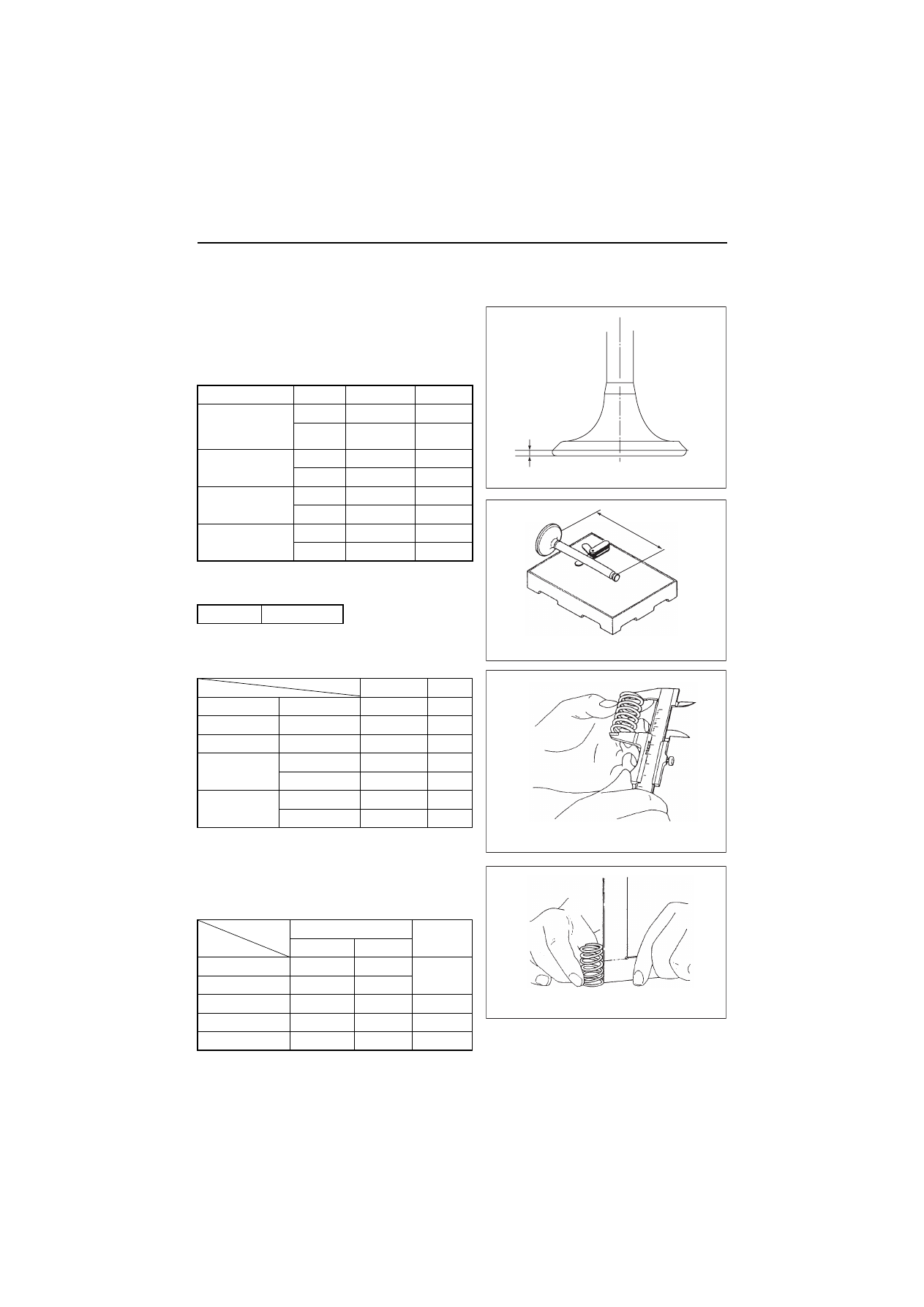
(3) Intake/exhaust valve

Mainly clean and check damage and wear at the valve stem and seat.
(a)

Seat contact: See (1)-(d) above.

(b)Stem outside diameter: See (2) above.
(c)Valve head thickness

(d)

Valve stem bend

(e)Overall length

(4) Valve spring

Mainly inspect damage and corrosion.

mm

Model

Part

Standard

Limit

3TNV82A to 88
4TNV84
(2-valve head)

Intake

1.24-1.44

0.8

Exhaust

1.35-1.55

0.8

4TNV84T
(4-valve head)

Intake

1.00-1.20

0.6

Exhaust

1.00-1.20

0.6

4TNV94L•98 (T)
(4-valve head)

Intake

1.44-1.84

1.0

Exhaust

1.70-2.10

1.0

4TNV106(T)
(4-valve head)

Intake

1.60-2.00

1.2

Exhaust

1.80-2.20

1.2

mm

Limit

0.01

mm

Standard

Limit

3TNV82A

Intake/Exhaust

97.2-97.8

97.0

3/4TNV84 to 88 Intake/Exhaust 108.7-109.3

108.5

4TNV84T

Intake/Exhaust 100.0-100.6

99.8

4TNV94L
4TNV98(T)

Intake

102.3-103.1

102.1

Exhaust

102.4-103.2

102.2

4TNV106(T)

Intake

117.3-118.1

117.1

Exhaust

117.1-117.9

116.9

mm

Free length

Inclination 

limit

Standard

Limit

3TNV82A

44.4

43.9

1.4

3/4TNV84 to 88

42.0

41.5

4TNV84T

37.4

36.9

1.3

4TNV94L•98(T)

39.7

39.2

1.4

4TNV106(T)

50.6

50.1

1.5

Thickness

Valve head thickness

Stool

Length

Valve bend and length

Free length

Valve spring

Inclination

Valve spring

4.  Disassembly, inspection and reassembly of engines

79

(5) Valve rocker arm

Mainly inspect valve head cap contact surface, inside
surface defects and wear.
Slight surface defects shall be corrected with an
oilstone.

(6) Rocker arm shaft

Mainly inspect seizure and wear at the surface in sliding

contact with the arm.


The rocker shaft diameter shall be

as specified in (5) above.

(7) Push rod

Mainly inspect the surface in contact with the tappet and 
adjusting screw. Slight defects shall be corrected with an 
oilstone.

(8) Valve clearance adjusting screw

Mainly inspect the surface in contact with the push rod.
Slight defects shall be corrected with an oilstone.

(9) Rocker arm spring

Mainly inspect surface defects and corrosion.

(R.1)

mm

Model

Items

Standard

Limit

3TNV82A
3/4TNV84(T)
3/4TNV88

Arm hole

diameter

16.00 to 16.02 16.07

Shaft O.D. 15.97 to 15.98 15.94

Clearance

0.016 to 0.054

0.13

4TNV94L/98(T)
4TNV106(T)

Arm hole

diameter

18.50 to 18.52 18.57

Shaft O.D. 18.47 to 18.49 18.44

Clearance

0.01 to 0.05

0.13

Bend limit

0.03 mm

Rocker arm hole diameter

Rocker shaft outside diameter

Thickness gage

Push rod bend

4.  Disassembly, inspection and reassembly of engines

80

4.2.6 Valve seat correction

[NOTICE]

Always check the oil clearance between the valve and valve guide before correcting the valve seat. If it
exceeds the limit, replace the valve or valve guide first to make the clearance satisfy the standard. After
correction, wash the valve and the cylinder head sufficiently with diesel oil to remove all grinding powder or
compound.

1)If the seat surface is slightly roughened: perform 

[A]

 and 

[B]

 below.

[A]: 

Lap the valve and seat with a mixture of valve

compound and engine oil.

[B]: 

Lap with engine oil only.

2)If the seat is heavily roughened but the width is

almost normal, correct with a seat grinder or seat
cutter first. Then perform lapping 

[A]

 and 

[B]

.

3)If the seat is heavily roughened and the width is

much enlarged, grind the seat inner surface with a
seat grinder whose center angle is 40°, then grind
the seat outer surface with a grinder whose center
angle is 150° to make the seat width match the stan-
dard. Then perform seat correction as described in
2), and then carry out lapping 

[A]

 and 

[B]

.

intake

Exhaust

Seat cutter angle

120

90

Grinding wheel angle

θ 

1

θ 

2

40

150

Seat cutter

40

q

Seat width

Seat angle

150

q

Cylinder head correction angle

Grindstone

Grinder

Seat grinder

4.  Disassembly, inspection and reassembly of engines

81

4.2.7 Valve guide replacement

1)Use a valve guide extraction tool (12.1-1 in Chapter 12) and extract the valve guide from the cylinder

head.

2)Put liquid nitrogen or ether (or alcohol) with dry ice added in a container and put the valve guide for

replacement in it for cooling. Then insert it in with a valve guide inserting tool (Refer to No.2 of 4.1.2 in
Chapter 4).

Do not touch the cooled valve guide with bare hands to avoid skin damage.

3)Check the inside diameter and finish to the standard

inside diameter as required with a reamer.

4)Check the projection from the cylinder head.

(R.1)

mm

Model

Number of valves

Projection 

3TNV82A

2 valves

11.7 to 12.0

4TNV84
3TNV84 (T)
4TNV88

14.7 to 15.0

4TNV84T

4 valves

8.2 to 8.5

4TNV94L
4TNV98(T)

9.7 to 10.

4TNE106(T)

13.4 to 13.6

Valve guide extracting
& inserting tool

Valve guide

Cylinder head

Projection

Valve guide replacement

4.  Disassembly, inspection and reassembly of engines

82

4.2.8 Valve stem seal replacement

Always use a new seal after the intake/exhaust valve is
disassembled. Since the one for the exhaust valve is
marked with yellow paint, do not confuse the intake and
exhaust valves.

1)Apply engine oil to the lip.
2)Push with the inserting tool (Refer to No.5 of 4.1.2 in

Chapter 4) for installation.

3)Measure and check the projection of valve stem seal

to keep proper clearance between valve guide and
stem seal.

mm

Model

Number of valves

Projection

3TNV82A

2 valves

15.7 to 16.0

4TNV84
3TNV84 (T)
4TNV88

18.7 to 19.0

4TNV84T

4 valves

9.9 to 10.2

4TNV94L
4TNV98 (T)

11.7 to 12.0

4TNE106 (T)

15.4 to 15.6

Valve stem seal inserting tool

Stem seal

Valve guide

Cylinder head

Stem seal insertion

Stem seal

Valve guide

Stem seal projection

Valve guide projection

Clearance

4.  Disassembly, inspection and reassembly of engines

83

4.3 Gear train and camshaft

4.3.1 Components

4.3.2 Disassembly procedure:

Disassemble in the order of the numbers in the illustration.

1)Perform steps 1) to 12) of the cylinder head disassembly procedure.
2)Remove the cooling water pump.
3)Remove the crankshaft pulley. (See 

Point 1

 of 4.3.4)

4)Remove the gear case cover. (See 

Point 2

 of 4.3.4)

5)Remove the fuel injection pump. (See 

Point 3

 of 4.3.4)

6)Remove the idle gear assy. (See 

Point 4

 of 4.3.4)

7)Remove the PTO drive gear. (See 

Point 5

 of 4.3.4)

8)Remove the starting motor.
9)Remove the flywheel. (See 

Point 6

 of 4.3.4)

10) Remove the camshaft assy. (See 

Point 7

 of 4.3.4)

11) Remove the gear case. (See 

Point 8

 of 4.3.4)

12) Remove the oil seal from the gear case cover. (See 

4.3.6

)

4.3.3 Reassembly procedure:

Reverse of the disassembly procedure.

Ԡ

Flywheel

Ԣ

Gear case flange

ԡ

Camshaft

ԙ

Cooling water pump

Camshaft driving gear

ԟ

Starter

Flywheel housing

Fuel pump spacer

Ԝ

Fuel injection pump

Fuel pump drive gear

Flange bolt

Don't disassemble!

Pump flange

Note) This figure shows the 3TNV84.

ԛ

Gear case

Crankshaft
gear

ԣ

Oil seal

Ԛ

Crankshaft pulley

ԝ

Idle gear

4.  Disassembly, inspection and reassembly of engines

84

4.3.4 Servicing points

Point1

[Disassemble]
• Remove the crankshaft pulley using a gear puller

after removing the crankshaft pulley set bolt. When
removing the pulley using the gear puller, use a pad
and carefully operate so as not to damage the thread.
Set the gear puller securely to prevent the pulley from
being damaged.

[Reassemble]
• Apply lithium grease to the oil seal lips. For the oil

seal with double lips dust seal, further slightly apply
engine oil on the lips so as not to damage them.

• Clean by wiping off any oil on both taper surfaces

using detergent.

• Be sure to use the crankshaft pulley installing tool so

as not to damage the oil seal lips. (See 4.3(6) Oil seal
replacement)

• When installing the crankshaft pulley, apply lube oil to

the set bolt to tighten and carefully assemble so as
not to damage the oil seal.

Point2

[Reassemble]
• When installing the gear case, do not forget to install

the two reinforcing bolts at the center.

• Measure the backlash of each gear.

• Apply sealant and install the gear case by correctly

positioning the two dowel pins.

(R.1)

N•m (kgf•m)

Model

Tightening torque

3TNV82A to TNV88

112.7 to 122.7 (11.5 to 12.5)

4TNV94L/98/106(T)

107.9 to 127.5 (11.0 to 3.0)

mm

3TNV82A to 88

Standard

Limit

Crankshaft gear,
Camshaft gear,
Fuel injection pump gear,
Idle gear, PTO gear,

0.07 to 0.15

0.17

4TNV94L-106(T)

Standard

Limit

Crankshaft gear,
Camshaft gear,
Fuel injection pump gear,
Idle gear, PTO gear,

0.08 to 0.14

0.16

Balancer gear
(only 4TNV106(T))

0.12 to 0.18

0.20

Lubricating oil pump gear

0.09 to 0.15

0.17

Gear train (4TNV94L to 106)

B

B

A

A

C

C

Idle gear

Crankshaft gear

Direction of rotation

Lubricating oil
pump gear

Fuel injection pump
drive gear

Camshaft gear

PTO gear

Gear train (3TNV82A to 4TNV88)

B

B

A

C

C

Idle gear

Crankshaft gear

Direction of rotation

Fuel injection pump
drive gear

Camshaft gear

PTO gear

4.  Disassembly, inspection and reassembly of engines

85

Point3: (Refer to 7.2.5 in chapter 7)

[Disassemble]
• Remove the mounting nut of the fuel injection pump

drive gear, remove the gear using the gear puller, and
remove the fuel injection pump. Do not forget to
remove the stay on the rear side. When extracting
the gear using the gear puller, use a pad at the shaft
and carefully operate so as not to damage the thread.

[Reassemble]
• Tightening torque for fuel pump drive gear nut (with-

out lube. Oil)

Point4

[Reassemble]
• Assemble crankshaft gear A, fuel injection pump

drive gear B and camshaft gear C at the same time
by aligning with idle gear A, B and C marks.

• Install the idle gear shaft with the oil hole facing

upward.

Point5

[Reassemble]
• Install the PTO drive gear with its inner spline side

facing the flywheel.

Point6

[Disassemble]
• Install a bolt as a handle in the hole at the end face of

the flywheel and remove carefully so as not to dam-
age the ring gear.

[Reassemble]
Flywheel mounting bolt : apply lube oil

Point7

[Disassemble]
• Measure the camshaft side gap.

• If the measured side gap exceeds the limit, replace

the thrust metal.

N•m (kgf•m)

Model

Tightening torque

TNV82A to 88

78 to 88 (8.0 to 9.0)

4TNV94L/98/106 (T)

113 to 123 (11.5 to 12.5)

N•m (kgf•m)

Model

Tightening torque

3TNV82A to 88

83.3 to 88.2 (8.5 to 9.0)

4TNV94L/98/106 (T)

186.2 to 205.8 (19.0 to 21.0)

mm

Item

Standard

Limit

Side gap

0.05 to 0.20

0.30

Gear train (3TNV82A to 4TNV88)

B

B

A

C

C

Idle gear

Crankshaft gear

Direction of rotation

Fuel injection pump
drive gear

Camshaft gear

PTO gear

4.  Disassembly, inspection and reassembly of engines

86

[Disassemble]
• Since the camshaft gear is shrink-fit, heat it to 

180°C to 200°C for extraction.

• For camshaft removal, raise the engine with its mount-

ing flange at the bottom. After removing the thrust
metal mounting bolt from the camshaft gear hole,
extract the camshaft carefully so as not to damage the
bearing bushing.

• Rotate the camshaft a few turns before extracting it to

prevent the tappet from being caught by the cam.

• After removing the camshaft, set the engine horizontal

and fix it on the base.

Unforeseen injury may arise due to falling of slipping
when raising the engine vertically or returning it to the
horizontal position. Proceed carefully so as not to lose
balance.

Point8: Gear case

[Reassemble]
• Do not forget to install the oil pan mounting bolts on the

bottom side when installing the gear case.

• Apply sealant (code No.977770-01212) and install the

gear case by matching the two dowel pints.

4.  Disassembly, inspection and reassembly of engines

87

4.3.5 Parts inspection and measurement

(1) Camshaft

Mainly check the contact between the tappet and cam contact surface, bearing seizure and wear, and gear
damage.

(a)Shaft bend measurement

Support the camshaft with V blocks. Rotate the camshaft
and measure the runout at the center of the camshaft
and at each journal with a dial gage. Half of the runout is
the bend.

(b)

Intake/exhaust cam height measurement

(c)

Camshaft and bearing hole measurement

Measure the camshaft outside diameter with a
micrometer. The oil clearance shall be calculated by
subtracting the measured camshaft outside diameter
from the inside diameter of the camshaft bearing or
bushing. The camshaft bushing at gear case side is
measured with a cylinder gage after insertion to the
cylinder.

mm

Item

Standard

Limit

Bend

0 to 0.02

0.05

mm

Model

Standard

Limit

3TNV82A to 88 38.600 to 38.800

38.350

4TNV94L•98

43.400 to 43.600

43.150

4TNV106 (T)

50.900 to 51.100

50.650

Water leak check in cooling water system

Cap tester

Flywheel side

Micrometer

Camshaft outside diameter

4.  Disassembly, inspection and reassembly of engines

88

(2) Idle gear

Mainly check the bushing seizure and wear, and gear
damage.
Shaft outside diameter and bushing inside diameter
measurement

(3) PTO drive gear

Mainly check sticking of bearings on both sides, gear
damage and looseness, and gear shaft damage and
wear.

mm

Model

Place

Item

Standard

Limit

3TNV82A to TNV88

Gear side

Bushing I.D.

44.990 to 45.055

45.130

Camshaft O.D.

44.925 to 44.950

44.890

Oil clearance

0.040 to 0.130

0.240

Intermediate position

Bushing I.D.

45.000 to 45.025

45.100

Camshaft O.D.

44.910 to 44.935

44.875

Oil clearance

0.065 to 0.115

0.225

Wheel side

Bushing I.D.

45.000 to 45.025

45.100

Camshaft O.D.

44.925 to 44.950

44.890

Oil clearance

0.0500.100

0.210

TNV94L/98 (T)

Gear side

Bushing I.D.

49.990 to 50.055

50.130

Camshaft O.D.

49.925 to 49.950

49.890

Oil clearance

0.040 to 0.130

0.240

Intermediate position

Bushing I.D.

50.000 to 50.025

50.100

Camshaft O.D.

49.910 to 49.935

49.875

Oil clearance

0.065 to 0.115

0.225

Wheel side

Bushing I.D.

50.000 to 50.025

50.100

Camshaft O.D.

49.925 to 49.950

49.890

Oil clearance

0.05 to 0.100

0.210

4TNV106(T)

Gear side

Bushing I.D.

57.980 to 58.050

58.105

Camshaft O.D.

57.910 to 57.940

57.875

Oil clearance

0.040 to 0.140

0.250

Intermediate position

Bushing I.D.

58.000 to 58.030

58.105

Camshaft O.D.

57.895 to 57.925

57.860

Oil clearance

0.075 to 0.135

0.245

Wheel side

Bushing I.D.

58.000 to 58.030

58.105

Camshaft O.D.

57.910 to 57.940

57.875

Oil clearance

0.050 to 0.120

0.230

mm

Item

Standard

Limit

Shaft outside diameter

45.950 to 49.975

45.900

Bushing inside diameter

46.000 to 46.025

46.075

Clearance

0.025 to 0.075

0.175

Shaft

Idle gear

Idle gear

Inside diameter

Shaft diameter

4.  Disassembly, inspection and reassembly of engines

89

4.3.6 Oil seal replacement (Gear case side)

1)Replace the oil seal with a new one when the gear case is disassembled.

Extract the used oil seal.

2)Insert a new oil seal. Fit the position of the oil seal insertion to the end face of the gear case. (Refer to the

below figure.)

3)Apply lithium grease to the oil seal tips. For the oil seal with double lips dust seal, further,

slightly apply engine oil on the oil seal lip so as not to damage them, when installing the
pulley.

[NOTICE]

Pay attention not to drop any oil on the taper surface of the crankshaft. If dropped, clean by wiping off using
detergent.

4)Carefully install the crankshaft pulley so as not to damage the oil seal lips. Especially for the engine

installed the oil seal with double lips dust seal, be sure to use the crankshaft pulley-installing tool.

4.3.7 Camshaft bushing replacement

Replace the bushing using the special service tool (Refer to No.7 of 4.1.2 in Chapter 4).

1.6

26

20

46

0.2

25

M14

˜

1.5

A

1

C1

C0.5

C0.5

C0.5

A

16

Ǟ

Knurled head
(Rollet)

Oil seal with doule lips dust seal

Guiding

Crankshaft pulley installing tool

Crankshaft pulley

Oil seal with double lips dust seal

Detail of crankshaft pulley
installing tool (Scale: free)
(Local supply)

For 4TNV94L engine installed

the oil seal with double lips

dust seal

#

17

Ǟ

35

Ǟ

39

4.  Disassembly, inspection and reassembly of engines

90

4.4 Cylinder block

4.4.1 Components

4.4.2 Disassembly procedure:

Disassemble in the order of the numbers in the illustration.

1)Perform steps 1) to 12) in the cylinder head disassembly procedure.
2)Perform steps 1) to 12) in the gear train disassembly procedure.
3)Remove the oil pan. (See 

Point 1

 of 4.4.4)

4)Remove the lubricating oil suction pipe.
5)Remove the piston w/rod. (See 

Point 2

 of 4.4.4)

6)Remove the mounting flange. (See 

Point 3

 of 4.4.4)

7)Remove the bearing metal caps. (See 

Point 4

 of 4.4.4)

8)Remove the crankshaft. (See 

Point 5

 of 4.4.4)

9)Remove the tappets.

10)Remove the pistons and rings. (See 

Point 6

 of 4.4.4)

11)Remove the oil seal from the mounting flange. (See 

4.4.8

 of 4.4.4)

4.4.3 Reassembly procedure:

Reverse of the disassembly procedure.

ԡ

Piston ring

Ԝ

Piston & Connecting rod

ԝ

Flywheel hausing

Ԡ

Tappet

ԛ

Oil suction pipe

Ԛ

Oil pan spacer

Ԟ

Bearing cap

Ԛ

Oil pan

Note) This figure shows the 3TNV84.

Oil filter

Flywheel

Oil seal

Ԣ

Oil seal case

ԟ

Crankshaft

Gear case flange

4.  Disassembly, inspection and reassembly of engines

91

4.4.4 Servicing points

Point1: Oil pan

[Disassemble]
• Sealant is applied to the oil pan mounting surface on

the block. Carefully operate soas not to damage or
distort the bonding surface.

[Reassemble]
• Apply sealant (code No.977770-01212) before reas-

sembly.

Point2: Piston w/rod

[Disassemble]
• Measure the connecting rod side gap.

• Carefully remove the carbon deposit on top of the cyl-

inder so as not to damage the inner side of the cylin-
der.

• Set the piston at the BDC position and remove the

connecting rod cap. Then set the piston at the TDC
position, and push the connecting rod big end with
the wooden shaft of a hammer. Proceed carefully so
as not to cause the cylinder block catch the rod big
end. Set the rod caps and crankpin metals in their
correct combinations.

[Reassemble]
• Apply oil especially carefully to the sliding contact

surfaces of the pistons, rods and rings.

• Use the piston insertion tool (see 12.1-9 in Chapter

12) to insert each piston w/rod in the cylinder block
and install the bearing metal cap.

Point3: mounting flange

[Disassemble]

Place the engine on a stable base with the cylinder
block upper surface facing down, and remove the
mounting flange carefully so as not to damage the
combustion surface.

mm

Standard

0.20 to 0.40

Rod bolt tightening torque                    N•m (kgf•m)

Model

Standard (apply lube oil)

3TNV82A

37.2 to 41.2 (3.8 to 4.2)

TNV84 to 88

44.1 to 49.0 (4.5 to 5.0)

4TNV94L•98

53.9 to 58.8 (5.5 to 6.0)

4TNV106(T)

78.5 to 83.4 (8.0 to 8.5)

Crankshaft

Thickness gage

Connecting rod side gap

4. Disassembly, inspection and reassembly of engines

[Reassemble]

Apply sealant (code No.977770-01212) and install the
mounting flange by matching the two dowel pins. After
assembly, raise the engine with its mounting flange on
the bottom side.

Unforeseen injury may arise due to falling of slipping
when raising or reversing the engine. Carefully
operate so as not to lose balance.

Point4: Journal bearing cap

[Disassemble]
• Before removing the journal bearing, measure the

crankshaft side gap. Measure it in either method
because there are the next two methods.

1)Install a dial gage on the cylinder block, and move a

crankshaft in front and back, and measure the side
gap as shown in the right figure.

2)Put a thickness gauge in the clearance between

thrust metal and crankshaft directly, and measure it.

Side gap standard

[Reassemble]
• If the side gap exceeds the standard, replace the

thrust metal with an oversize one.
Machine the standard width of the crankshaft thrust
part into the dimension of the below table at the same
time.
Refer to a parts catalog when ordering the part.
The surface finishing precision (refer to 4.4.5(2) in
Chapter4):

mm

Model

Standard

Limit

3TNV82A to 88

0.140 to 0.220

0.28

4TNV94L to 106

0.130 to 0.230

0.28

Side gap measurement 1

Cylinder block

Crankshaft

Thrust metal

Bearing cap

Standard

width

face

Thrust

Thickness gauge

Side gap measurement 2

4.  Disassembly, inspection and reassembly of engines

93

[Disassemble]
• Remove the bearing caps, cap side bearings, and

thrust metals. Place each thrust metal with identifica-
tion of the position and direction.
The position number of reassembling is punched on
a metal cap (except for both ends) and a cylinder
block.

[Reassemble]
• Carefully install each thrust metal so that the grooved

one is positioned away from the cap.

• Do not confuse the upper and lower main bearing

metals. The upper main bearing metal (block side)
has an oil hole, and the lower one does not. The
“arrow” marks on the cap shall face the flywheel.
Tighten main bearing cap bolts.

Main bearing cap bolt tightening torque 
(apply lube oil)

Point5: Crankshaft

[Disassemble]
• Remove the crankshaft. Remove each main bearing

metal upper (block side) and pair it with the metal cap
side lower metal.

Carefully prevent damage to the bearing or finger
injury when removing the crankshaft because it is
heavy.

N•m (kgf•m)

Model

Standard 

3TNV82A

76.4 to 80.4 (7.8 to 8.2)

TNV848 to 8

93.2 to 98.1 (9.5 to 10.5)

4TNV94L•98

108.1 to 117.9 (11.0 to 12.0)

4TNV106(T)

186.2 to 205.8 (19.0 to 21.0)

Thrust metals

Block side main

bearing metals

Cap side main

bearing metals

Main bearing

Wheel side

Gear side

Upper main bearing metal 

Oil hole

Lower

Main bearing cap

Groove

Thrust metal

( 9

Mark

Position number
of reassembling

Journal bearing cap

ࡎࠗ࡞


Content      ..     53      54      55      56     ..