Takeuchi compact excavator TB125, TB135, TB145 / diesel TNE / diesel Yanmar. Service Manual - page 53
 

  Index      Manuals     Takeuchi compact excavator TB125 (12510003~), TB135 (13510004~), TB145 (14510004~) / diesel TNE / diesel Yanmar. Service Manual


Search            copyright infringement  


Content      ..     51      52      53      54     ..


Takeuchi compact excavator TB125, TB135, TB145 / diesel TNE / diesel Yanmar. Service Manual - page 53


2.  Inspection and adjustment

47

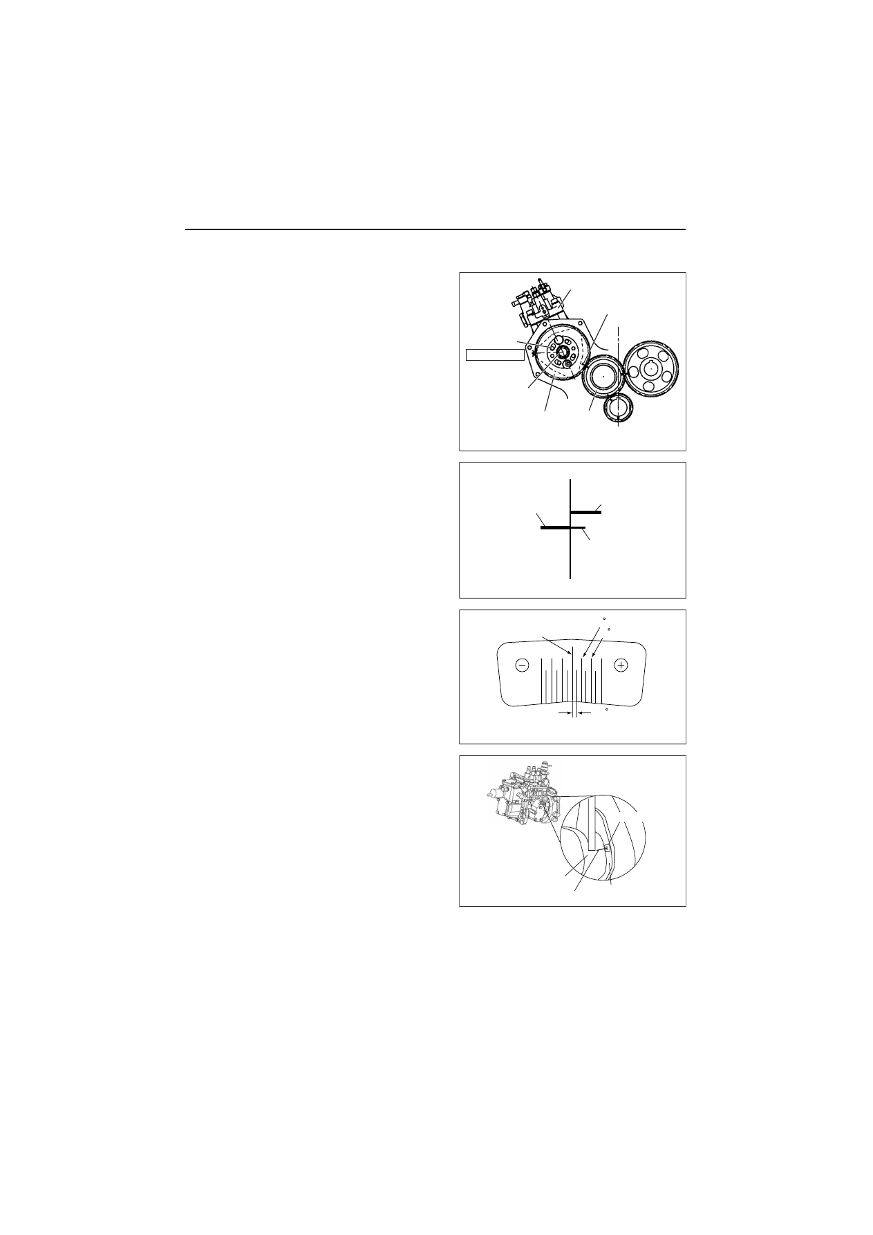
The adjustment of fuel injection angle 

θ

i

In case that the fuel pump are removed, and
reassembled, the procedure of fuel injection angle
adjustment is as follows. (As for the disassembly of a
fuel injection pump, refer to 7.2.3 in chapter 7.)

[NOTICE]

Never loosen four flange bolts, which fasten a pump
flange and a fuel pump drive gear at the time of the
removal of the fuel pump. When it is loosened, the
adjustment of the fuel injection timing becomes very
difficult.

1)Before removing a fuel pump drive gear, make ID

marks on the gearing part of the pump drive gear and
the idle gear with paint and so on.

2)Make the mark-off line to the gear case precisely in

accordance with the position of mark-off line of the
fuel pump.

3)Before removing a fuel pump, put the standard mark

of a sticker for fuel injection angle adjustment in
accordance with the mark-off line of the fuel pump
and paste it on the gear case.

(R.1)

Fuel injection pump

I.D.mark

Gear

installation nut

Flange bolt

Don't loosen!

Fuel pump

drive gear

Idle gear

Fuel pump installation angle

Fuel pump side

Mark-off line
on fuel pump

Gear case side

Mark-off line
on gear case

Marking

Marking on gear case

Standard mark

Sticker for adjusting injection angle

cam

1

cam

2

cam

0.5

Gear case

Fuel injection pump

Mark-off line

Mark sticker

2.  Inspection and Adjustment

48-1

4)Remove a fuel pump, and read the fuel injection angle recorded in that fuel pump.

5)Read the injection angle recorded on a newly assembled fuel pump and calculate the difference from the

injection angle of the disassembled fuel pump. (When re-installation does the same fuel pump, the angu-
lar difference is zero.)
Fuel injection angle difference 


θ

i

 (cam angle) = (the fuel injection angle 

θ

i2

 of a new fuel pump)

- (the fuel injection angle 

θ

i1

 of a disassembled previous fuel pump)

Calculation example

[NOTICE]

Tell the fuel pump number to Yanmar, and inquire the injection angle of the pump when it is hard to find out.

6)Put the fuel pump on the gear case temporarily and install the drive gear on the cam shaft with checking

the ID marks, which were put on the fuel pump drive gear and the idle gear at the time of the disassem-
bling.

Tighten the installation nut of a pump drive gear.

7)Adjust the installation angle of the fuel pump while

reading the injection angle difference, calculated in
the above 5), withe the mark (minimum 0.5°, cam
angle) of the adjustment mark sticker..

[NOTICE]

Push down the fuel pump in the outside direction of the
cylinder block at +0.5 degree(cam) when a injection
angle difference 


θ

i

 is +0.5 degree(cam).

And, push it down to the cylinder block side at 0.3
degree(cam) when a difference is -0.3 degree(cam).

8)Tighten the fuel pump installation nuts.

(R.1)

Fuel injection angle 
difference

(degree, cam angle)

Fuel injection angle 
of a new fuel pump 

θ

i2

(degree, cam angle)

Fuel injection angle 
of a disassembled 
fuel pump 

θ

i1

(degree, cam angle)

Fuel pump installation method

+0.5

8.5

8.0

Turn the fuel pump body in the outside 
directon of the cylinder block at 0.5 
degree(cam angle).
[Advanced injection timing]

-0.3

7.7

8.0

Turn the fuel pump body in the inside 
direction of the cylinder block at 0.3 
degree(cam angle).
[Delayed injection timing]

Model

Fuel pump model

Tightening torque

N•m (kgf•m)

Lubricating oil application

(thread portion, and seat surface)

3TNV82A to TNV88

MP2

78 to 88 (8 to 9)

Not applied

4TNV94L/98/106 (T)

MP4

113 to 123 (11.5 to 12.5)

Injection angle adjustment

Incase of 

cam

-0.3

In case of +

cam

0.5

Standard

mark

Mark-off ling on fuel pump

Mark sticker

cam

1

cam

1

cam

0.5

cam

0.5

2.  Inspection and Adjustment

48-2

 (Supplementary explanation 1)

The installation angle of the fuel pump is as follows.

(Supplementary explanation 2)

When fuel injection timing is advanced or delayed, the
installation angle of the fuel pump is adjusted.
When fuel injection timing is advanced for example at
0.5 degrees(cam), loosen the nuts, which fix the fuel
pump on the gear case, and turn the fuel pump body in
the inside direction of the cylinder block at 0.5
degree(cam), and tighten the pump installation nuts.
And, when fuel injection timing is delayed, a pump is
turned in that reverse direction.

(R.1)

Model

Installation angle

θ

 (deg.)

3TNV82A to TNV88

25

4TNV94L/98/106 (T)

13

4TNV106 (T)

11.5

Fuel pump installation angle

ǰ

Cylinder block side

Injection timing adjustment

Cylinder block side

Pump installation bolts

Advanced

Delayed

2.  Inspection and Adjustment

49

2.3 Adjusting the no-load maximum or minimum speed

1)After warming the engine up, gradually raise the speed and set it at the no-load maximum revolution.
2)If the no-load maximum speed is out of the stan-

dard, adjust it by turning the high idle limiting bolt.
The no-load maximum speed standard is shown in
the specification tables in 1.2 of the chapter 1.

3)Then set the no-load minimum speed by adjusting

the low idle limiting bolt.


Note) The engine speed may differ from the above

standard depending on an engine installed on a
machine unit.

 No-load minimum speed standards            (Unit: min

-1

)

Engine application

 class

No-load minimum speed

(± 25)

CL

1200

VM

800

(1100 for 4TNV106 (T))

Low

High

Accelerating wire fixing nut

High idle
limiting bolt

Accelerating wire bracket

MP2 Fuel Injection pump

Accelerating
wire bracket

Low idle
limiting bolt

Govenor lever

2.  Inspection and Adjustment

50

2.4 Sensor inspection

2.4.1 Oil pressure switch

Disconnect the connector from the oil pressure switch.
Keep the voltameter probes in contact with the switch
terminal and cylinder block while operating the engine. It
is abnormal if circuit is closed.

2.4.2 Thermo switch

Place the thermo switch in a container filled with
antifreeze or oil. Heat it while measuring the fluid
temperature. The switch is normal if the voltameter
shows continuity when the fluid temperature is 
107 to 113 deg C.

2.5 Water leak check in cooling water system

Check coolant water leakage from the cooling water
system visually. If any problem is found, Inspect as
follows.

1)Fill coolant water to the normal level in the radiator,

and install the cap tester on the radiator.

2)Operate the manual pump to set the pressure to 

0.09 ± 0.015 MPa (0.9 ± 0.15 kgf/cm

2

). If the cap

tester pressure gage reading drops then, water is
leaking from the cooling water system. Check the
water leaking point.

(R.1)

Continuity test

Tester probes

Oil pressure switch

Cylinder block
(flywheel side)

Thermometer

Hot water

Tester probes

Thermo switch

Water leak check in cooling water system

Cap tester

2.  Inspection and Adjustment

51

2.6 Radiator cap inspection

Install the radiator cap on the cap tester. Set the tester

pressure to 0.09 ± 0.015 MPa (0.9 ± 0.15 kgf/cm

2

) and

see that the cap is opened. If the cap does not open,
replace the cap since it is abnormal.

2.7 Thermostat Inspection

Place the thermostat in a container filled with water.
Heat it while measuring the water temperature, and see
that the thermostat is actuated at temperature of
following table.

* Valve opening temperature is carved on the flange. 

Model

Valve opening

Temperature

(deg C)*

Full open lift 

(Temperature)

(mm)

All models

69.5 to 72.5

8 or more (85 deg C)

Radiator cap inspection

Radiator cap

To radiator

Cover

Thermostat

Thermo switch

Thermometer

Thermostat

2.  Inspection and Adjustment

52

2.8 Adjusting operation

Perform the adjusting operation of a engine as follows after the maintenance job:

1)Supply the fuel oil, lubricating oil and coolant water.

Note:
Check the levels of the lubricating oil and coolant water again after test running (for about 5 minutes) and add
as required.

2)Start the engine, and carry out idling at a low revolution (700 to 900 rpm) for a few minutes.
3)Run in the engine for about five minutes at the rated revolution (no-load). Check any water, fuel or oil leak

and existence of abnormal vibration or noise. Also check the oil pressure, coolant water temperature and
exhaust gas color.

4)Adjust the no-load minimum and maximum revolutions according to the specifications.
5)Perform loaded operation as required.

2.9 Long storage

Observe the following instructions when the engine is to be stored for a long period without operation:

1)Be sure to use clean soft water added Long Life Coolant Antifreeze (LLC) in the cooling water system and

do not drain the coolant before long-term storage.
If drain the cooling water, it will cause to built up rust due to the residual water in the cooling water system.

2)Remove the mud, dust and oil deposit and clean the outside.
3)Perform the nearest periodic inspection before the storage.
4)Drain or fill the fuel oil fully to prevent condensation in the fuel tank.
5)Disconnect the battery cable from the battery negative (-) terminal.
6)Cover the silencer, air cleaner and electric parts with PVC (Poly Vinyl Chloride) cover to prevent water and

dust from depositing or entrance.

7)Select a well-ventilated location without moisture and dust for storage.
8)Perform recharging once a month during storage to compensate for self-discharge.
9)When storing an engine for long time, run the engine or do motoring periodically according to the following

procedure.  Because the rust occurrence inside the engine, the rack agglutination of the fuel pump, and so
on are likely to occur. (In case that the engine is equipped with a machine unit,)

a)Replace the lube oil and the filter before the engine running.
b)Supply fuel if the fuel in the fuel tank was removed, and bleed the fuel system.
c)Confirm that there is the coolant in the engine.
d)Operate the engine at the low idling speed for about five minutes. (If it can be done, one a month)

3.  Troubleshooting

53

3. Troubleshooting

3.1 Preparation before troubleshooting

If the signs of a trouble appear, it is important to lecture on the countermeasure and treatment before
becoming a big accident not to shorten the engine life.

When the signs of a trouble appear in the engine or a trouble occurs, grasp the trouble conditions fully by the
next point and find out the cause of sincerity according to the troubleshooting. Then repair the trouble, and
prevent the recurrence of the trouble.

1)What’s the occurrence phenomenon or the trouble situation? 

⋅⋅⋅⋅⋅

 (e.g. Poor exhaust color)

2)Investigation of the past records of the engine

Check a client control ledger, and examine the history of the engine.

• lInvestigate the engine model name and the engine number. (Mentioned in the engine label.)

Examine the machine unit name and its number in the same way.

• lWhen was the engine maintained last time?
• lHow much period and/or time has it been used after it was maintained last time?
• lWhat kind of problem was there on the engine last time, and what kind of maintenance was dane?

3)Hear the occurrence phenomenon from the operator of the engine in detail.

5W1H of the occurrence phenomenon : the investigation of when (when), where (where), who (who), what  

(what), why (why) and how (how)

• lWhen did the trouble happen at what kind of time?
• lWas there anything changed before the trouble?
• lDid the trouble occur suddenly, or was there what or a sign?
• lWas there any related phenomenon. 

⋅⋅⋅⋅⋅

. (e.g. Poor exhaust color and starting failure at the same time)

4)After presuming a probable cause based on the above investigation, investigate a cause systematically by

the next troubleshooting guide, and find out the cause of sincerity.

3. TROUBLESHOOTING

54

3.2 Quick reference table for troubleshooting

The following table summarizes the general trouble symptoms and their causes. If any trouble symptom occurs, take corrective action before it becomes a serious problem so as not to shorten the engine service life.

3. TROUBLESHOOTING

3. TROUBLESHOOTING

56

3. TROUBLESHOOTING

57

3.3 Troubleshooting by measuring compression pressure

Compression pressure drop is one of major causes of increasing blowby gas (lubricating oil contamination or
increased lubricating oil consumption as a resultant phenomenon) or starting failure. The compression
pressure is affected by the following factors:

1)Degree of clearance between piston and cylinder
2)Degree of clearance at intake/exhaust valve seat
3)Gas leak from nozzle gasket or cylinder head gasket

In other words, the pressure drops due to increased parts wear and reduced durability resulting from long use
of the engine.
A pressure drop may also be caused by scratched cylinder or piston by dust entrance from the dirty air
cleaner element or worn or broken piston ring. Measure the compression pressure to diagnose presence of
any abnormality in the engine.

(1) Compression pressure measurement method

1)After warming up the engine, remove the fuel

injection pipe and valves from the cylinder to be
measured.

2)Crank the engine before installing the compres-

sion gage adapter.
*1) Perform cranking with the stop handle at the

stop position (no injection state).

*2) See 12.2-18 in Chapter 12 for the compression 

gage and compression gage adapter.

3)Install the compression gage and compression

gage adapter at the cylinder to be measured.
*1) Never forget to install a gasket at the tip end of 

the adapter.

4)With the engine set to the same state as in 2)*1),

crank the engine by the starter motor until the
compression gage reading is stabilized.

(2) Standard compression pressure

Engine compression pressure list (reference value)

(R.1)

Engine mode

Compression pressure 

at 250 min

-1

MPa (kgf/cm

2

)

Deviation among cylinders

MPa (kgf/cm

2

)

Standard

Limit

3TNV82A

3.04 ± 0.1 (31 ± 1)

2.45 ± 0.1 (25 ± 1)

0.2 to 0.3 (2 to 3)

3/4TNV84

3.24 ± 0.1 (33 ± 1)

2.55 ± 0.1 (26 ± 1)

3/4TNV84T

2.94 ± 0.1 (30 ± 1)

2.45 ± 0.1 (25 ± 1)

TNV88 to 106 (T) 3.43 ± 0.1 (35 ± 1)

2.75 ± 0.1 (28 ± 1)

Compression
gage

Measurement of the compression pressure 

3. TROUBLESHOOTING

58

(3) Engine speed and compression pressure (for reference)

(4) Measured value and troubleshooting

When the measured compression pressure is below the limit value, inspect each part by referring to the table
below.

No.

Item

Cause

Corrective action

1

• Air cleaner element

• Clogged element
• Broken element
• Defect at element seal 

portion

• Clean the element.
• Replace the element.

2

• Valve clearance

• Excessive or no clear-

ance

• Adjust the valve clearance.

(See 3.5 in Chapter 3.)

3

• valve timing

• Incorrect valve clearance • Adjust the valve clearance.

(See 3.5 in Chapter 3.)

4

• Cylinder head gasket

• Gas leak from gasket

• Replace the gasket.
• Retighten the cylinder head bolts to the spec-

ified torque.
(See 4.2 (2) 12) in Chapter 4.)

5

• Intake/exhaust vale
• Valve  seat

• Gas leak due to worn 

valve seat or foreign mat-
ter trapping

• Sticking valve

• Lap the valve seat.

(See 4.2 (6) in Chapter 4.)

• Replace the intake/exhaust valve.

6

• Piston
• Piston ring
• Cylinder

• Gas leak due to scratch-

ing or wear

• Perform honing and use an oversized part.

(See 4.4 (5)-(5-1), (5-4) and (6) in Chapter 4.)

200                 250                  300                 350                 400

Engine speed (min

-1

)

3/4TNV84

3TNV82A

3/4TNV84T

40

4

3

2

35

30

25

20

Compression pressure (kgf/cm

2

)

Compression pressure (MPa)

3/4TNV88

4TNV106(T)

4.  Disassembly, inspection and reassembly of engines

59

4. Disassembly, inspection and reassembly of engines

4.1 Complete disassembly and reassembly

4.1.1 Introduction

Make preparation as follows before starting engine inspection and service:

1)Fix the engine on a horizontal base.

Be sure to fix the engine securely to prevent injury or damage to parts due to falling during the work.

2)Remove the coolant water hose, fuel oil pipe, wire harness, control wires etc. connecting the driven

machine and engine, and drain coolant water, lubricating oil and fuel.

3)Clean soil, oil, dust, etc. from the engine by washing with solvent, air, steam, etc. Carefully operate so as

to prevent any foreign matter from entering the engine.

Always wear glasses or other protectors when using compressed air or steam to prevent any foreign matter
from getting in the eyes.

[NOTICE]

• Any part which is found defective as a result of inspection or any part whose measured value does not sat-

isfy the standard or limit shall be replaced.

• Any part predicted to dissatisfy the standard or limit before the next service as estimated from the state of

use should be replaced even when the measured value then satisfies the standard or limit.

4.  Disassembly, inspection and reassembly of engines

60

4.1.2 Special service tools

(1) Special Tools

No. 

Tool name 

Applicable model and tool size 

Illustration 

Valve guide tool 
(for extracting valve 
guide) 

Model 

L1 L2 d1 d2 

3TNV82A 
4TNV94L 98(T)
4TNV106(T) 

20 75 6.5

10 

4TNV84 
3TNV84(T) 
3/4TNV88 

20 75 7.5

11 

4TNV84T 20 

75 

5.5


̪

Locally manufactured 


Valve guide tool 
(for inserting valve 
guide) 

Model 

L1 L2 d1 d2 

3TNV82A 

12 60 13 19 

4TNV84 
3TNV84(T) 
3/4TNV88 

15 65 14 20 

4TNV84T 

8.5

60 11 17 

4TNV94L 98(T)

7  60 13 16 

4TNV106(T) 

13.6

65 13 16 


̪

Locally manufactured 


Connecting rod 
bushing replacer 
(for removal / 
installation of 
connecting rod 
bushing) 

Model 

L1 L2 d1 d2 

3TNV82A 

25 85 23 26 

TNV84 88 20 

100

26 

29 

4TNV94L 98 20 

100

30 

33 

4TNV106(T) 20 

100

37 

40 


Allowance:    

3

.

0

6

.

0

1

d

3

.

0

6

.

0

2

d


̪

Locally manufactured 


Valve spring 
compressor  
(for removal / 
installation of valve 
spring) 

yanmar code No. 

129100-92630 


-

-

-

-

4.  Disassembly, inspection and reassembly of engines

61

(R.1)

No. 

Tool name 

Applicable model and tool size 

Illustration 

Stem seal insertion 
(for inserting stem 
seal) 

     চ


Model d1

d2

d3

L1

L2

L3

3TNV82A 15.2

21

12

15.8

65

4

4TNV84 
3TNV84(T) 
4TNV88 

16.2

22

13.5

18.8

65

4

4TNV84T 12.9

19

11.5

10.0

65

4

4TNE94L 98 15.2

21

12

11.8

65

4

4TNE106(T) 15.2

21

12

15.5

65

4

̪

Locally manufactured 


Filter wrench 
(for removal / 
installation of L.O. 
filter) 

Available on the market 


Camshaft bushing 
tool 
(for extracting 
camshaft bushing) 

Model 

L1 L2 d1 d2 

TNV82A 88 

18 70 45 48 

4TNV94L 98 

18 70 50 53 

4TNV106(T) 

18 70 58 61 

Allowance:    

3

.

0

-
-

-
-

6

.

0

1

d

3

.

0

6

.

0

2

d

̪

Locally manufactured 


Flex-Hone 
(For re-honing of 
cylinder liner) 

Model Parts 

No. 

Cylinder 

bore 

  (

)

TNV82A  129400-92420

78 84 

TNV88

4TNV94L

129400-92430

83 95 

4TNV98 129400-92440

89 101 

4TNV106(T) 129400-92450

95 108 


Piston insertion 
tool 
(for inserting 
piston) 

 
Yanmar code No. 95550-002476 

̪

The above piston insertion tool is applicable 

to 60-125 mm diameter pistons. 


10 

Piston ring replacer 
(for removal / 
installation of 
piston ring) 
 

Available on the market 


11 

Crankshaft pulley 
installing tool 

Locally manufactured 
(for 4TNV94L) 
(Refer to 4.3.6 in detail) 


Content      ..     51      52      53      54     ..