Takeuchi compact excavator TB125, TB135, TB145 / diesel TNE / diesel Yanmar. Service Manual - page 54
 

  Index      Manuals     Takeuchi compact excavator TB125 (12510003~), TB135 (13510004~), TB145 (14510004~) / diesel TNE / diesel Yanmar. Service Manual


Search            copyright infringement  


Content      ..     52      53      54      55     ..


Takeuchi compact excavator TB125, TB135, TB145 / diesel TNE / diesel Yanmar. Service Manual - page 54


4.  Disassembly, inspection and reassembly of engines

62

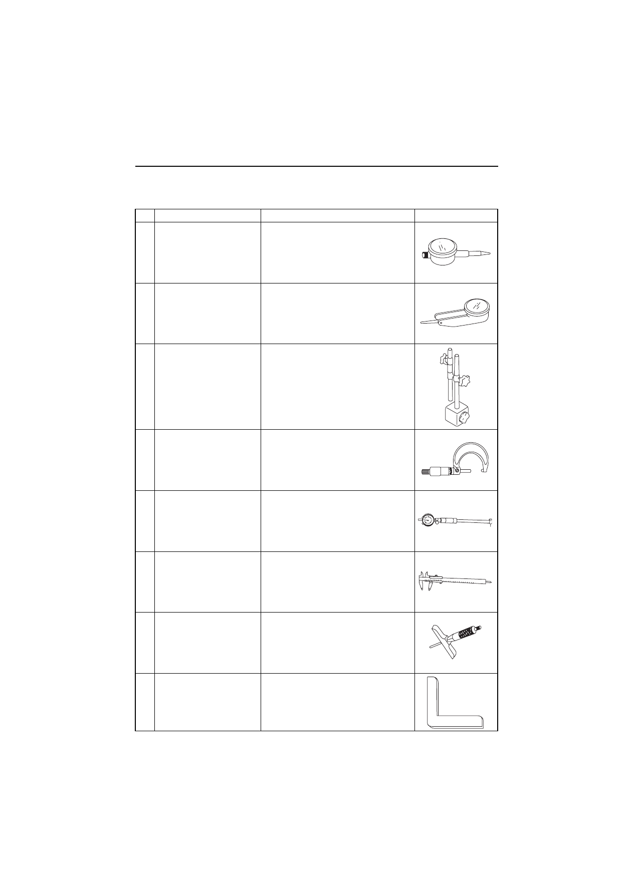
(2) Measuring instruments

No.

Instrument name

Application

Illustration

1

Dial gage

Measurements of shaft bending, and strain 
and gap of surfaces

2

Test indicator

Measurements of narrow or deep portions 
that cannot be measured by dial gage

3

Magnetic stand

For holding the dial gage when measuring 
using a dial gage, standing angles adjustable

4

Micrometer

For measuring the outside diameters of 
crankshaft, pistons, piston pins, etc.

5

Cylinder gage

For measuring the inside diameters of 
cylinder liners, rod metal, etc.

6

Calipers

For measuring outside diameters, depth, 
thickness and width

7

Depth micrometer

For measuring of valve sink

8

Square

For measuring valve spring inclination and 
straightness of parts

4.  Disassembly, inspection and reassembly of engines

63

No.

Instrument name

Application

Illustration

9

V-block

For measuring shaft bend

10 Torque wrench

For tightening nuts and bolts to the 
specified torque

11 Thickness gage

For measuring gaps between ring and ring 
groove, and shaft joints during assembly

12 Cap tester

For checking water leakage

13 Battery coolant tester

For checking concentration of antifreeze 
and the battery electrolyte charge status

14 Nozzle tester

For measuring injection spray pattern of 
fuel injection nozzle and injection pressure

15 Digital thermometer

For measuring temperatures

abcdefghijklmn

abcdefghijklmn

abcdefghijklmn

abcdefghijklmnabcdefghijklmn

abcdefghijklmnabcdefghijklmn

abcdefghijklmn

abcdefghijklmn

abcdefghijklmn

abcdefghijklmn

abcdefghijklmn

abcd  efghijk

abcd  efghijk

Float

4.  Disassembly, inspection and reassembly of engines

64

(R.1)

No.

Instrument name

Application

Illustration

16 Speedometer

Contact type

For measuring revolution by contacting 
the mortise in the revolving shaft

Photoelectric type

For measuring revolution by sensing 
the reflecting mark on the outer 
periphery of the revolving shaft

17 Circuit tester

For measuring resistance, voltage and 
continuity of electrical circuits

18 Compression gage kit

For measuring compression pressure

Gauge set code NO. TOL-97190080

Adapter for direct injection 2-valve head

Adapter code No. 119802-92950

Adapter for direct injection 4-valve head 
for 4TNV94L/98/98T

Adapter code No. 129906-92950

Adapter for direct injection 4-valve head 
for 4TNV106/106T

Adapter code No. 123907-92950

Revolving shaft

Reflection mark

130

165

179

4.  Disassembly, inspection and reassembly of engines

65

4.1.3 Complete disassembly

Peripheral parts such as air cleaner, muffler and radiator differ in installation and types for each application.
Therefore, description in this Chapter is started with the steps to be taken just after the peripheral parts have
been removed.

Step

Removal Parts

Remarks

1

1)Thoroughly remove sand, dust, dirt and soil

from the surface of the engine.

2)Drain coolant water and lubricating oil from the

engine.

2

1)Remove turbocharger and exhaust manifold.
2)Remove intake manifold and surge tank.

3

1)Close the fuel cock valve of the fuel tank.
2)Remove high-pressure fuel pipe.
3)Remove fuel return pipe.
4)Loosen the tightening nut on fuel injection noz-

zle retainer and extract the retainer and fuel
injection nozzle.

*) Fuel injection nozzle for Indirect injection 

system is screwed type.

1)If nozzle seat is left on the cylinder head,

remove the cylinder head before extracting noz-
zle seat.

2)To prevent dust from entering fuel injection noz-

zle, fuel injection pump and high-pressure fuel
pipe, seal their respective threads with a tape or
the like.

3)Whenever extracting fuel injection nozzle,

replace nozzle protector with a new one.

4

1)Remove rocker arm cover assembly.

5

1)Remove valve rocker arm shaft assembly.
2)Remove push rod.

1)Attach a tag to push rod for each cylinder No. to

put the push rod in order.

2)Remove valve cap from the intake/exhaust

valve head.

3)Note that tappet of the indirect injection system

can be removed at the same time when push
rod is extracted.

4)Attach a tag to tappet for each cylinder No. to

put the tappet in order.

6

1)Remove fan mounting bolt, and then remove

fan.

2)Loosen adjusting bolt for the V-belt adjuster, and

then remove V-belt.

3)Remove alternator.
4)Remove the spacer for cooling fan and V-pulley.

1)Never turn down alternator vigorously toward

the cylinder block. Otherwise, your finger may
be nipped and alternator broken.

7

1)Remove lubricating oil filter assembly.
2)Extract dipstick form the oil dip-stick hole.

8

1)Disconnect fuel return pipes to.
2)Remove fuel filter.

4.  Disassembly, inspection and reassembly of engines

66

Step

Removal Parts

Remarks

9

1)Disconnect coolant water pipe from the cooling

water pump.

2)Remove thermostat assembly.
3)Remove cooling water pump.

10

1)Remove cylinder head tightening bolt.
2)Remove cylinder head assembly.
3)Remove cylinder head gasket.

1)Lay a cardboard or the like on the floor and

place cylinder head assembly on it so as not to
damage the combustion surface.

2)Order of loosening the cylinder head tightening

bolts.

3)To remove the intake/exhaust valves from cylin-

der head assembly, take the following steps.
a)Using a valve spring compressor (see Chapter 

5, 5-1), compress valve spring and remove 
valve cotter.

b)Remove valve retainer and valve spring.
c)Remove intake valve and exhaust valve.

11

1)Remove crankshaft V-pulley clamping bolt.
2)Using a puller, extract crankshaft V-pulley.

1)Extract crankshaft V-pulley by hitting the bolt of

the puller using a plastic hammer or the like.

12

1)Remove oil pan mounting bolt under gear case.
2)Remove gear case mounting bolt.
3)Remove gear case.

1)Never fail to removes stiffener bolt at the center

of the gear case.

2)When removing the gear case, carefully protect

oil seal from damage.

13

1)Remove the nut from fuel injection pump drive

gear. Extract fuel injection pump drive gear
using a puller.

1)Before removing fuel injection pump, make sure

of the position of the arrow of the pump body for
adjusting fuel injection timing as well as the posi-
tion of the scribed line of the gear case flange.
(Applies only to direct injection system.)

1

2

3

5

4

6

10

12

8

13

14

11

9

7

3 cylinder head

Camshaft side

Disassembly

Disassembly

Head bolt disassembly order

Fan side

Fan side

Camshaft side

1

2

3

5

4

6

15

10

14

17

18

13

16

11

12

8

9

7

4 cylinder head

Head bolt disassembly order

4.  Disassembly, inspection and reassembly of engines

67

Step

Removal Parts

Remarks

14

1)Remove lubricating oil pump.

15

1)Remove starting motor from flywheel housing

sing.

16

1)Remove flywheel mounting bolt.
2)Remove flywheel.

1)Carefully protect the ring gear from damage

mage.

17

1)Remove flywheel housing.
2)Remove oil seal case with a screwdriver or the

like by utilizing grooves on both sides of oil seal
case.

1)Carefully protect the oil seal from damage.

18

1)Remove oil pan and spacer.

1)Put the cylinder block with the attaching surface

of the cylinder head facing down.

2)Carefully protect the combustion surface of the

cylinder block from damage.

3)For indirect injection system, be careful to the

possibility of the tapped to drop off when the cyl-
inder block is turned upside down, because the
tappet is cylindrical in shape.

19

1)Remove idle gear shaft, and then remove idle

gear.

2)Remove mounting bolt of thrust bearing through

the hole of the camshaft gear. Remove cam-
shaft assembly.

1)Turn the cylinder block aside and carefully pre-

vent tappet from jamming on the cam.

2)Preheat camshaft gear and camshaft assembly

to 180° to 200° which are shrink fitted, before
removing them.

20

1)Remove gear case flange.

21

1)Remove lubricating oil strainer.

22

1)Remove crankpin side cap of the connecting

rod.

While turning crankshaft, place piston in the 
bottom dead center (BDC).

1)Before extracting piston, remove carbon depos-

its from the upper wall of the cylinder using fine
sandpaper, while taking care not to damage the
inner surface of the cylinder.

2)Make sure than cap No. of connecting rod

agrees with cylinder No.

3)Take care not to let crankpin metal fall when

removing connecting rod crankpin side cap.

4.  Disassembly, inspection and reassembly of engines

68

Step

Removal Parts

Remarks

23

1)Remove main bearing cap bolt. While shaking

main bearing cap, remove main bearing cap
together with lower main bearing metal.

2)Extract crankshaft, taking care not to damage it.
3)Remove upper main bearing metal.

1)Before extracting crankshaft, measure the side

gap around it.

Apply a dial gauge to the end of crankshaft. 
Force the crankshaft on both sides in the axial 
direction to measure the thrust gap. 
Alternatively, insert a thickness gauge directly 
between the base thrust metal and the thrust 
surface of the crankshaft to measure the gap.
If the limit size is exceeded, replace the thrust 
metal with a new one.

Thrust gap (All models)
2)Notice on the removal of thrust metal.
a)When removing thrust metal, ascertain the 

position and direction where thrust metal is 
installed in relation to the cap.

b)Make sure that the thrust metal groove is 

outward in relation to the cap.

24

1)Remove piston and connecting rod assembly.

1)To selectively remove a desired piston and con-

necting rod assembly without extracting crank-
shaft, take the steps itemized below:

a)Remove carbon deposits from the upper wall of 

the cylinder using fine sandpaper, taking care 
not to damage the inner surface of the cylinder.

b)While turning the crankshaft, with the 

connecting rod cap removed, raise the piston up 
to the top dead center (TDC).

c)Extract the piston/connecting rod assembly 

while tapping the connecting rod at the large end 
with the handle of a plastic hammer or the like.

25

2)Remove tappet.

Crankshaft

Dial gauge

4.  Disassembly, inspection and reassembly of engines

69

4.1.4 Precautions before and during reassembly

To reassemble engine components, reverse the procedure of disassembly. However, follow the precautions
below and the precautions from in chapter 4 to in chapter 7 particularly before and during reassembly.

(1) Cleaning the component

Use particular care to clean the cylinder block, cylinder head, crankshaft, and camshaft. Ensure that they are
free from chips, dust, sand, and other foreign matter.

(2) Parts to be replaced during reassembly

Be sure to replace the following parts with new ones during assembly.

• Valve stem seal
• Head gasket packing
• Nozzle protector and nozzle seat of the fuel injection valve
• Various copper packing, O-rings and gasket packing.

4.1.5 Adjusting operation

Make sure to perform adjusting operation after completing reassembly. Refer to section 2.5 in chapter 2 for
the operation procedure.

4.  Disassembly, inspection and reassembly of engines

70

4.2 Cylinder head: Disassembly, inspection and reassembly

4.2.1 Components (2-valve cylinder head)

4.2.2 Disassembly procedure:

Disassemble in the order of the numbers shown in the illustration.

1)Remove the alternator assy. (Point1)
2)Remove the fan, pulley and V belt.
3)Remove the thermostat case. (Point2)
4)Remove the fuel filter and fuel oil piping. (Point3)
5)Remove the oil level gage assy.
6)Remove the oil filter. (Point4)
7)Remove the fuel injection pipes. (Point5)
8)Remove the intake manifold assy.
9)Remove the exhaust manifold assy.

10)Remove the rocker arm cover assy.
11)Remove the rocker shaft assy, push rods and valve caps. (Point6)
12)Remove the cylinder head assy and head gasket. (Point7)
13)Remove the fuel injection valves and fuel return pipe. (Point8)
14)Remove the intake/exhaust valves, stem seals and valve springs. (Point9)
15)Remove the rocker arms from the rocker shaft.

ԡ

Rocker arm cover

Cylinder head

Ԟ

Fuel injection pipe

ԟ

Intake maniforld

Head gasket

ԙ

V-pulley

Cooling water pump

Ԛ

Thermostat

Ԙ

Oil cooler

Thermo switch

ԙ

Fan

Spacer

Joint

Ԡ

Exhaust manifold

ԛ

Fuel filter

Oil/water separator

ԝ

Oil filter

Cylinder block

Gear case

Note) This figure shows the 3TNV84.

4.  Disassembly, inspection and reassembly of engines

71

4.2.3 Reassembly procedure:

Reverse order of the disassembly procedure.

Rocker arm shaft

Adjusting bolt

Rocker arm

cover

Rocker arm

Rocker arm

suport

Valve bridge

Cotter

Spring holder

Valve spring

Stem seal

Valve guide

Cylinder head

Exhaust valve

Suction valve

4-Valve cylinder head

2-Valve cylinder head

Rocker arm suport

Rocker arm

Rocker arm shaft

Valve cap

Cotter

Spring holder

Valve spring

Stem seal

Valve guide

Cylinder head

Exhaust vlave

Suction valve

Rocker arm

cover

4.  Disassembly, inspection and reassembly of engines

72

4.2.4 Servicing points

Point1

[Disassemble]
• Loosen the mounting bolt while supporting the alter-

nator.

Do not tilt the alternator toward the cylinder block in
haste since it may damage the alternator or pinch a
finger.

[Reassemble]
• The belt deflection shall be checked according to

2.2.2. in Chapter2.

[Reassemble]
• Replace the belt with a new one if cracked, worn or

damaged.

• Carefully prevent the belt from being smeared with oil

or grease.

Point2

[Reassemble]
• Check the thermostat function. (See3.9 in Chapter 3

for the check procedure.)

Pont3

[Reassemble]
• Replace the fuel filter element with a new one.
[Disassemble]
• Cover the fuel pipe opening with tape to prevent

intrusion of foreign matters.

Point4

[Reassemble]
• Replace the oil filter with a new one.
• After fully tightening the filter manually, retighten it

with a filter wrench (see 11.1-6 in Chapter 11) by 3/4
turn.

Point5

[Disassemble]
• Cover the fuel injection pipe and pump inlets and out-

lets with tape or the like to prevent intrusion of foreign
matters.

Adjuster

Adjust the V-belt tension
inserting a bar

Alternator

Tension adjustment

V-belt tention

98N (10kgf)

Set bolt

Crank pulley

Deflection

Alternator

C.W. pump

V belt

4.  Disassembly, inspection and reassembly of engines

73

Point6

1)Removing pipe seals of 4 valve head.
[Disassemble]
• Take off a rocker arm cover in case of 4 valve head

after removing fuel injection pipes and pipe seals.

[NOTICE]

Attention is necessary because a fuel nozzle is caught
in a pipe seal and the pipe seal is damaged when a
rocker arm cover is lifted with a pipe seal sticking to
the rocker arm cover.

• Insert a minus driver in the slit part of the rocker arm

cover, and remove it when removing a pipe seal.

[Reassemble]
• Replace the used pipe seal with a new one when

removing a pipe seal.

2)Breather system (A redactor to intake air system of

blowby gas)
Emitting blowby gas is harmful to natural environ-
ment. Therefore blowby gas redactor is adopted to
TNV series naturally- aspirated engines as breather
system (Turbocharged engines emitblowby gas).
The system of model 3/4TNV84 is shown as a repre-
sentative of that breather system in the right figure.
Some of the combustion gas passes through the
clearance between the cylinder and the piston, pis-
ton ring, and flows to the crankcase. This is said as
blowby gas. While it passes into the cylinder head
and the rocker arm cover, the blowby gas mixes with
splash oil, and becomes oil mist-blowby gas mixes
with splash oil, and becomes oil mist-blowby gas it
passing through the baffle plate inside a rocker arm
cover. And it passes through a diaphragm assy, and
a intake manifold, and is reduced in the combustion
chamber. Pressure inside a crankcase is controlled
by the function of the diaphragm assy, and suitable
amount of blowby gas is reduced in intake air sys-
tem.

[Disassemble]
When a rocker arm cover is taken off, check whether
oil or the like enter the diaphragm space from a small
hole on the side of a diaphragm cover or not without
disassembling the diaphragm.

Pipe seal

Fuel injection pipe

Fuel nozzle

Slit of bonnet

Pipe seal

Minus driver

Cap nut of fuel injection pipe

Pipe seal replacement

Center plate

Spring

Diaphragm

Diaphragm cover

Rocker arm cover

Breather

baffle

Baffle plate

Intake

maniforld

Breather pipe

Breather system componert

Blowby gas flow

Blowby gas flow

to diaphragm

space

Diaphragm part

Blowby gas flow

Baffle plate

Rocker arm

cover

Center plate

Cover

Spring

Diaphragm

4.  Disassembly, inspection and reassembly of engines

74

[NOTICE]

1)When a diaphragm is damaged, pressure control inside the crankcase becomes insufficient, and troubles

occur. When the internal pressure of the crankcase decreases too much due to the damage of a spring,
much blowby gas containing oil is reduced in intake air system, and it may cause the combustion defect
by the early dirt of the intake valve or the urgent rotation of the engine by the oil burning. 
When pressure progresses in the crank case too much due to the wrong operation of the diaphragm and
so on, it is considered that oil leakage from the joint of a oil pan, a oil seal and so on will occur. When a
diaphragm is damaged, blowby is discharged from the breathing hole on the side of diaphragm cover, and
not reduced in the intake manifold. Therefore, be careful of the diaphragm trouble.

2)At lubricating oil replacement or lube oil supply

The amount of lubricating oil isn't to be beyond the standard upper limit (in the engine horizontally, the
upper limit mark of the dip stick). Since the blowby gas redactor is adopted, be careful that the amount of
oil mist may be inducted in the combustion chamber and the oil hammer sometimes may occur, when the
lubricating oil quantity is beyond the upper limit or an engine is operated beyond the allowable maximum
angle of an engine.

[Reassembly]

Replace the diaphragm with new one, when it is damaged.

Point7

[Disassemble]
• Keep the removed push rods by attaching tags show-

ing corresponding cylinder Nos.

[Reassemble]
• Always apply oil to the contact portions of the push

rods and clearance adjusting screws.

Point8

[Disassemble]
• Loosen the cylinder head bolts in two steps in the

illustrated order.

• Place the cylinder head assy on a paper board to pre-

vent the combustion face from any damage.

[Reassemble]
• Remove the head gasket with a new one.
• Uniformly install the head bolts manually after apply-

ing oil on the threaded and seat portions.

• They shall be tightened in two steps in the reverse of

the order for disassembly.

• Tightening torque

N•m (kgf•m)

TNV82A

TNV84-88

First step

30.0 to 34.0

(3.1 to 3.5)

41.1 to 46.9

(4.2 to 4.8)

Second step

61.7 to 65.7

(6.3 to 6.7)

85.3 to 91.1

(8.7 to 9.3)

4TNV94L/98

4TNV106 (T)

First step

49.0 to 58.8

(5.0 to 6.0)

88.3 to 98.1

(9.0 to 10.0)

Second step

103.1 to 112.9

(10.5 to 11.5)

188.0 to 197.8

(19.0 to 20.0)

1

2

3

5

4

6

10

12

8

13

14

11

9

7

3 cylinder head

Camshaft side

Disassembly

Disassembly

Assembly

Assembly

Head bolt disassembly order

Fan side

Fan side

Fan side

1

2

3

5

4

6

10

12

8

13

14

11

9

7

3 cylinder head

Camshaft side

Camshaft side

Camshaft side

Head bolt tightning order

4 cylinder head

Head bolt tightning order

1

2

3

5

4

6

15

10

14

17

18

13

16

11

12

8

9

7

Fan side

1

2

3

5

4

6

15

10

14

17

18

13

16

11

12

8

9

7

4 cylinder head

Head bolt disassembly order

4.  Disassembly, inspection and reassembly of engines

75

Point9

[Disassemble]
• Carefully remove the fuel injection valve so as not to

leave the top end protector from being left inside the
cylinder.

[Reassemble]
• Replace the fuel injection valve protector with a new

one.

Point10

[Disassemble]
• When removing each intake/exhaust valve from the

cylinder head, use a valve spring compressor (see
11.1-4 in Chapter 11) and compress the valve spring
and remove the valve cotter.)

• Keep each removed intake/exhaust valve after

attaching a tag showing the corresponding cylinder
No.

• If cotter burr is seen at the shaft of each intake/

exhaust valve stem, remove it with an oilstone and
extract the valve from the cylinder head.

[Reassemble]
• Replace the stem seal with a new one when an

intake/exhaust valve is disassembled.

• Carefully install each valve after oil application so as

not to damage the stem seal.

• Different stem seals are provided for the intake and

exhaust valves. Do not confuse them since those for
exhaust valves are marked with yellow paint.

• After assembling the intake/exhaust valve, stem seal,

valve spring, seat, and cotter, tap the head of the
valve stem lightly for settling.

• Do not forget to install the valve cap.

Valve spring compressor

4.  Disassembly, inspection and reassembly of engines

76

4.2.5 Parts Inspection and measurement

(1) Cylinder head

Clean the cylinder head, mainly the combustion surface,
valve seats and intake/exhaust ports, remove carbon
deposit and bonding agent, and check the surface state.

(a)Appearance check

Check mainly discoloration and crack. If crack is
suspected, perform color check.

(b)Combustion surface distortion

Apply a strait-edge in two diagonal directions and on
four sides of the cylinder head, and measure distortion
with a thickness gage.

(c)

Valve sink

Measure with the valve inserted to the cylinder head.

(d)Seat contact

Apply a thin coat of minimum on the valve seat. Insert
the valve in the cylinder and push it against the seat to
check seat contact.

Standard: Continuous contact all around

mm

Standard

Limit

Distortion

0.05 or less

0.15

mm

Standard

Limit

3TNV82A
(2-valve head)

Intake

0.35 to 0.55

0.8

Exhaust 0.30 to 0.50

0.8

4TNV84
3TNV84 (T)
3/4TNV88
(2-valve head)

Intake

0.30 to 0.50

0.8

Exhaust 0.30 to 0.50

0.8

4TNV84T
4TNV94/98 (T)
(4-valve head)

Intake

0.36 to 0.56

0.8

Exhaust 0.35 to 0.55

0.8

4TNV106 (T)
(4-valve head)

Intake

0.5 to 0.7

1.0

Exhaust

0.7 to 0.9

1.2

Straight-edge

Thickness gage

Distortion at combustion surface

Valve sinking depth

Valve sink depth

Seat

Valve seat contact

Depth micrometer

Valve sink

4.  Disassembly, inspection and reassembly of engines

77

(2) Valve guide

Mainly check damage and wear on the inside wall.
Apply the service part code when replacing a part.

Valve stem clearance

Model

Service part code

3TNV82A
(2-valve)

Suction

124060-11800

Exhaust

119802-11810

4TNV84
3TNV84(T)
3/4TNV88
(2-valve)

Suction

120130-11860

Exhaust

129150-11810

4TNV84T
(4-valve)

Suc./Exh.

119717-11800

4TNV94L
4TNV98(T)
(4-valve)

Suc./Exh.

129907-11800

4TNV106(T)
(4-valve)

Suction

123907-11800

Exhaust

123907-11810

Model

Part name

Place

Standard

Limit

3TNV82A
(2-valve head)

Intake value

Guide I.D.

7.000 to 7.015

7.08

Stem O.D.

6.945 to 6.960

6.90

Clearance

0.040 to 0.070

0.18

Exhaust value

Guide I.D.

7.000 to 7.015

7.08

Stem O.D.

6.940 to 6.955

6.90

Clearance

0.045 to 0.075

0.18

4TNV84
3TNV84 (T)
3/4TNV88
(2-valve head)

Intake value

Guide I.D.

8.010 to 8.025

8.10

Stem O.D.

7.955 to 7.975

7.90

Clearance

0.035 to 0.070

0.18

Exhaust value

Guide I.D.

8.015 to 8.030

8.10

Stem O.D.

7.955 to 7.970

7.90

Clearance

0.045 to 0.075

0.18

4TNV84T
(4-valve head)

Intake value

Guide I.D.

6.000 to 6.015

6.08

Stem O.D.

5.960 to 5.975

5.90

Clearance

0.025 to 0.055

0.15

Exhaust value

Guide I.D.

6.000 to 6.015

6.08

Stem O.D.

5.945 to 5.960

5.90

Clearance

0.040 to 0.070

0.17

4TNV94L
4TNV98 (T)
(4-valve head)

Intake value

Guide I.D.

7.000 to 7.015

7.08

Stem O.D.

6.945 to 6.960

6.90

Clearance

0.040 to 0.070

0.17

Exhaust value

Guide I.D.

7.000 to 7.015

7.08

Stem O.D.

6.940 to 6.955

6.90

Clearance

0.045 to 0.075

0.17

4TNV106(T)
(4-valve head)

Intake value

Guide I.D.

7.008 to 7.020

7.08

Stem O.D.

6.960 to 6.975

6.92

Clearance

0.033 to 0.060

0.16

Exhaust value

Guide I.D.

7.008 to 7.020

7.08

Stem O.D.

6.945 to 6.960

6.90

Clearance

0.048 to 0.075

0.18

Measuring positions

a

b

c

A

B

Valve guide inside diameter

Measuring positions

Valve stem outside diameter


Content      ..     52      53      54      55     ..