Takeuchi compact excavator TB125, TB135, TB145 / diesel TNE / diesel Yanmar. Service Manual - page 52
 

  Index      Manuals     Takeuchi compact excavator TB125 (12510003~), TB135 (13510004~), TB145 (14510004~) / diesel TNE / diesel Yanmar. Service Manual


Search            copyright infringement  


Content      ..     50      51      52      53     ..


Takeuchi compact excavator TB125, TB135, TB145 / diesel TNE / diesel Yanmar. Service Manual - page 52


2.  Inspection and adjustment

31

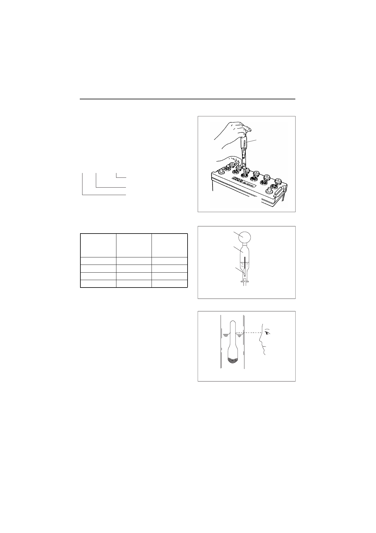
(b)Measurement with hydrometer

When using a hydrometer, the measured specific gravity
must be corrected according to the temperature at the
time of measurement. The specific gravity of battery
electrolyte is defined with 20 °C as the standard. Since
the specific gravity increases or decreases by 0.0007
when the temperature varies by 1 °C, correct the value
according to the equation below. 

(c)Specific gravity and remaining battery charge

(3) Terminals

Clean if corroded or soiled.

(4) Mounting bracket

Repair or replace it if corroded.
Retighten if loosened.

(5) Battery appearance

Replace the battery if cracked or deformed.
Clean with fresh water if contaminated.

Specific

gravity

(20 °C)

Discharged

quantity

of electricity

(%)

Remaining

charge

(%)

1.28

0

100

1.26

10

90

1.24

20

80

1.23

25

75

Float

Battery charge measurement
with a hydrometer

Hydrometer structure

Float

Glass tube

Rubber bulb

How to read hydrometer

S20 = St + 0.007(t-20)

Electrolyte temperature
at measurement
Specific gravity at measurement

Converted specific gravity at 20

͠

2.  Inspection and adjustment

32

2.2.4 Inspection every 250 hours or 3 months

Be sure to check the following points every 250 hours or 3 months operation, whichever comes first.

(1) Lube oil and filter replacement (The second replacement and after)

Replace the engine oil every 250 hours operation from 2nd time and on. Replace the engine oil filter at the
same time. Refer to 2.2.1.(1).

(2) Radiator fin cleaning

Beware of dirt from air blowing

Wear protective equipment such as goggles to protect your eyes when
blowing compressed air. Dust or flying debris can hurt eyes.

Dirt and dust adhering on the radiator fins reduce the
cooling performance, causing overheating. Make it a
rule to check the radiator fins daily and clean as
needed.

• Blow off dirt and dust from fins and periphery with

compressed air [0.19MPa (2 kgf/cm

2

) or less] not to

damage the fins with compressed air.

• If contaminated heavily, apply detergent, thoroughly

clean and rinse with tap water shower.

IMPORTANT:

Never use high pressure water or air from close by
fins or never attempt to clean using a wire brush.
Radiator fins can be damaged.

(3) V-belt tension check (The second time and after)

Check and adjust the V-belt tension. Refer to 2.2.2(2)

No.

Inspection Item

(1)

Lube oil and filter replacement

(2)

Radiator fin cleaning

(3)

V-belt tension check

(4)

Inspection and adjustment of governor lever and accelerator

(5)

Air cleaner cleaning and element replacement

Radiator fins

Dust, dirt

Air blow

2.  Inspection and adjustment

33

(4) Inspection and adjustment of governor lever and accelerator

The governor lever and accelerating devices
(accelerating lever, pedal, etc.) of the machine unit are
connected by an accelerating wire or rod. If the wire
becomes stretched or the connections loose, the
deviation in the position may result and make operation
unsafe. Check the wire periodically and adjust if
necessary.
Do not strongly move the accelerating wire or
accelerating pedal. It may deform the governor lever or
stretch the wire to cause irregular engine speed control.
Checking and adjusting procedure are as follows.

1)Check that the governor lever of the engine makes

uniform contact with the high idling and low idling
limiting bolt when the accelerating devices is in the
high idling speed or low idling speed position.

2)If either the high or the low idling speed side does

not make contact with the limiting bolt, adjust the
accelerating wire.
Loosen the accelerating wire fixing nut and adjust
the wire to contact with the limiting bolt.

Never release the limiting bolts. It will impair the safety and performance of the product and functions and
result in shorter engine life.

(5) Air cleaner cleaning and element replacement

Beware of dirt from air blowing

Wear protective equipment such as goggles to protect your eyes when
blowing compressed air. Dust or flying debris can hurt eyes.

The engine performance is adversely affected when the
air cleaner element is clogged by dust. So periodical
cleaning after disassembly is needed.

1)Undo the clamps on the dust pan and remove the

dust pan.

2)Loosen the wing bolt on the element and pull out the

element.

Low

High

Accelerating wire fixing nut

High idle
limiting bolt

Accelerating wire bracket

MP2 Fuel Injection pump

Accelerating
wire bracket

Low idle
limiting bolt

Govenor lever

OPTION

Air blow

Dust pan

latch

Air cleaner case

Arrow mark

Arrow
mark

Element

2.  Inspection and adjustment

34

3)Blow air [0.29 to 0.49 MPa (3.0 to 5.0 kgf/cm

2

)] from

inside the element to blow dust off as shown in the
illustration right.
Apply the air blowing pressure as low as possible so
as not to damage the element.
If having the air cleaner with double elements, never
remove and clean the inner element.
The aim of installing the inner element is for back up
protecting from intaking dust during engine running
when leaving the outer element to reinstall after
removing it or when damaging the outer element
unexpectedly during engine running.

4)Replace the element with new one, If the element is

damaged, excessively dirty or oily.

5)Remove the inside dust cover of the dust pan, and

clean inside of the dust pan.

6)Reinstall the element with the wing bolt. (do not

leave the gasket.) Reattach the inside dust cover to
the dust pan and install the dust pan to the air
cleaner case placing the TOP mark upward.

IMPORTANT:

• When the engine is operated in dusty conditions,

clean the element more frequently.

• Do not run the engine with removed air cleaner or

element, as this may cause foreign material to enter
and damage the engine.

Dust indicator (optional)

Air cleaner case

Arrow mark

Inner element

Double elements type air cleaner
with inner and outer element

Outer element

Dust pan

OPTION

latch

Arrow
mark

2.  Inspection and adjustment

35

2.2.5 Inspection every 500 hours or 6 months

Be sure to check the following points every 500 hours or 6 months operation, whichever comes first.

(1) Water separator cleaning

Periodically wash the water separator element and
inside cup with clean fuel oil.

1)Prepare a waste oil container.
2)Close the fuel cock.
3)Loosen the drain cock and drain.

Refer to 2.2.3.(2)

4)Turn the retaining ring counter-clockwise and

remove the cup.
(Disconnect the coupler of the lead wire for drain
sensor before removing the cup if it is with drain
sensor).

5)Wash the element and inside cup with clean fuel oil.

Replace the element with new one if any damaged.

6)Insert the element to the bracket (O-ring) and after

putting the float ring in the cup, install it to the
bracket by tightening the retaining ring clockwise.
Tightening torque: 15 to 20 N•m (1.5 to 2.0 kgf•m)

7)Close the drain cock (connect the coupler if with

drain sensor).

8)Bleed the fuel system. Refer to 2.2.3.(3)

No.

Inspection Item

(1)

Water separator cleaning

(2)

Fuel filter element replacement

(3)

Air cleaner cleaning and element replacement

Model

Applicable element Part No.

3TNV82A to
4TNV106 (T)

119802-55710

Air bleeding bolt

Outlet

Inlet

Close

Open

Cup

Float ring

Drain cock

Water separator

Fuel cock

2.  Inspection and adjustment

36

(2) Fuel filter element replacement

Replace the fuel filter at specified intervals, before it is
clogged with dust to adversely affect the fuel flow. Also,
replace the fuel filter after the engine has fully been
cooled.

1)Close the fuel cock of the water separator.
2)Remove the fuel filter using a filter wrench (customer

procured). When removing the fuel filter, hold the
bottom of the fuel filter with a piece of rag to prevent
the fuel oil from dropping. If you spill fuel, wipe such
spillage carefully.

3)Clean the filter mounting surface and slightly apply

fuel oil to the gasket of the new fuel filter.

4)Install the new fuel filter manually turning until it

comes into contact with the mounting surface, and
tighten it further to 1/2 of a turn using a filter wrench.
Tightening torque for 3TNV82A to 4TNV106 (T): 
20 to 24 N•m (2.0 to 2.4 kgf•m)

5)Bleed the fuel system. Refer to 2.2.3.(3)

IMPORTANT:

Be sure to use genuine Yanmar part (super fine mesh
filter). Otherwise, it results in engine damage, uneven
engine performance and shorten engine life.

(3) Air cleaner cleaning and element replacement

Replace the air cleaner element periodically even if it is not damaged or dirty.
When replacing the element, clean inside of the dust pan at the time.
If having the air cleaner with double elements, do not remove the inner element. If the engine output is still not
recover (or the dust indicator still actuates if having the air cleaner with a dust indicator) even though the outer
element has replaced with new one, replace the inner element with new one.

Model

Applicable fuel filter Part No.

3TNV82A to
4TNV88

119802-55800

4TNV98 (T) to
4TNV106 (T)

123907-55800

ߪࠆ

ߪࠆ

ψ

φ

ψ

Tighten

Loosen

2.  Inspection and adjustment

37

2.2.6 Inspection every 1,000 hours or one year

Be sure to check the following points every 1,000 hours or one year operation, whichever comes first.

(1) Cooling water replacement

Cooling water contaminated with rust or water scale
reduces the cooling effect. Even when antifreeze agent
(LLC) is mixed, the cooling water gets contaminated due
to deteriorated ingredients. Replace the cooling water at
least once a year.

Beware of scalding
by hot water

Wait until the temperature
goes down before draining
the coolant water. Otherwise,
hot water may splash to
cause scalding.

1)Remove the radiator cap.
2)Loosen the drain plug at the lower portion of the radi-

ator and drain the cooling water.

3)After draining the cooling water, tighten the drain

plug.

4)Fill radiator and engine with cooling water. 

a)Before filling, check to be sure the drain plug is closed.
b)Remove the radiator cap of the radiator by turning the radiator cap counter-clockwise about 1/3 of a 

turn.

c)Pour the cooling water slowly into the radiator up to the lip of the filler port so that air bubbles do not 

develop.

d)After supplying the cooling water, surely tighten the radiator cap. To fasten the radiator cap, align the 

detents on the back face of the radiator cap with the slot of the filler port and turn clockwise pushing it 
downward approx. 1/3 of a turn until contact with each other.

e)Remove the cap of the coolant recovery tank, supply the cooling water to the FULL mark and fasten the 

cap.

f)Check the rubber hose connecting the coolant recovery tank to the radiator. Be sure the rubber is 

securely connected and there is no looseness or damage. When the rubber hose is not water tight, an 
excessive amount of cooling water will be consumed.

No.

Inspection Item

(1)

Cooling water replacement

(2)

Diaphragm assy inspection

(3)

Turbocharger blower cleaning*

(4)

Intake/exhaust valve clearance adjustment

(5)

Fuel injection nozzle pressure inspection

Radiator cap

Rubber hose

Coolant
recovery tank

Drain plug
(Drain plug location depends on the machine unit)

(Max.limit)

FULL

LOW
(Min.limit)

OPTION

2.  Inspection and adjustment

38

g)When filling with the cooling water for the first time or replacing, the air contains in the cooling water 

system. So, as the air in the cooling water system is self-bleeded during engine operation, the cooling 
water level in the radiator and coolant recovery tank will be lowered. Replenish the cooling water into the 
radiator and coolant recovery tank until it reaches the FULL mark of the coolant recovery tank.

ƒ

Daily check of the cooling water level and refilling can be done by observing the coolant recovery
tank. 

ƒ

The cooling water capacity of the radiator depends on the machine unit. Refer to the operation
manual provided by the equipment manufacturer.

ƒ

Check the cooling water level when the engine is cold. Cooling water flows to the coolant
recovery tank when the radiator is still hot and makes accurate checks impossible.

ƒ

Check the radiator and hoses for leakage.

(2) Diaphragm assy inspection

Inspect the diaphragm assy on the rocker arm cover
every 1000 hours or 

2 years

. Refer to 4.2.4 point 6 for

the function of the diaphragm.

1)Loosen screws, and remove a diaphragm assy, and

check whether oil and so on doesn’t enter between
the diaphragm and the cover. If oil and so on enters
into the diaphragm assy, the diaphragm doesn’t work
well.

2)Check the damages of the diaphragm rubber and

the spring. If necessary, replace with new ones.

[NOTICE]

• When a diaphragm is damaged, pressure control

inside the crankcase becomes insufficient, and trou-
bles such as combustion defect and so on occur.

• At lubricating oil replacement or lubricating oil supply,

the amount of lubricating oil isn’t to be beyond the
standard upper limit. If the lubricating oil quantity is
beyond the upper limit or an engine is operated
beyond the allowable maximum angle of an engine,
the amount of oil mist may be inducted in the com-
bustion chamber and the oil hammer sometimes may
occur.

Center plate

Spring

Diaphragm

Diaphragm

cover

Rocker arm

cover

Breather

baffle

Baffle plate

Intake

maniforld

Breather pipe

Breather system componert

2.  Inspection and adjustment

39

(3) Turbocharger blower cleaning*

When engine speed seems sluggish or the exhaust color looks poor, the blades of the turbocharger-blower
may be dirty.
Wash the turbine blower in such a case.

(a)General items

1)As for washing, use washing liquid and clear water.
2)Washing time is the time when about 10% of the boost pressure decreases more than that of usual oper-

ation state as a standard.

3)Disassemble and clean a turbocharger periodically because the whole of the turbocharger can’t be

cleaned in this method.

(b)Washing point

1)A specified quantity of washing liquid/water is poured with a filler (ex. Oil sprayer) from the air inlet of the

blower gradually (about ten seconds) at the normal load (3/4-4/4) of an engine.
And, perform this work at no-load after load running of the engine, if it is difficult to pour the liquid into the
blower at load running.

Specified quantity of washing liquid/water

It causes an accident when large quantity of washing liquid is poured rapidly into a turbocharger.

2)Pour the same amount of clear water as washing liquid/water into the blower about 3-5 minutes later after

the washing liquid/water injection and wash it.

It causes an accident when large quantity of water is poured rapidly into a turbocharger.

3)Repeat the washing after then minutes when there is no change with the boost pressure or the exhaust

gas temperature after washing.
When there is no change at all even if it repeats 3-4 times, disassemble and maintain the turbocharger
because of the cruel dirt of the blower or other causes.

4)Operate the engine at load for at least 15 minutes after washing, and dry.

Turbocharger model

RHB31, RHB51

Injection amount, one time

20 cc

2.  Inspection and adjustment

40

(4) Intake/exhaust valve clearance adjustment

Make measurement and adjustment while the engine is
cold.

(a)Valve clearance measurement

1)Remove the rocker arm cover above cylinder head.
2)Set the No.1 cylinder in the compression TDC

Turn the crankshaft to bring the piston of the No.1 cyl-
inder to its compression top dead center while watch-
ing the rocker arm motion, timing scale and the top
mark position of the crankshaft pulley.
(Position where both the intake and exhaust valves
are closed.)

Notes:

• The crankshaft shall be turned clockwise as seen from

the radiator side.

• The No.1 cylinder position is on the opposite side of

the radiator and the ignition order shall be 1-3-4-2-1 at
180° intervals.

• Since the intake and exhaust valve rocker arms are

operated the same and there is a clearance between
the arm and valve generally at the top dead center, the
position can be checked by means of the play when
the arm head is held with a hand. Also see that the
crankshaft pulley top mark is positioned at zero on the
timing scale. If there is no valve clearance, inspection
in the disassembled state is necessary since the valve
seat may be worn abnormally.

3)Valve clearance measurement

In case of 2-valve cylinder head insert a thickness
gage between the rocker arm and valve cap, and
record the measured valve clearance.
In case of 4-valve head insert a thickness gage
between the rocker arm and the valve bridge, and
record the measured valve clearance.
(Use it as the data for estimating the wear state.)

4)Adjusting other cylinders

In case of 4-cylinder engines, turn the crankshaft
180° and make adjustment for the No.3 cylinder.
Then adjust the No.4 and No.2 cylinders in this order.
The cylinder to be adjusted first does not have to be
the No.1 cylinder. Select and adjust the cylinder
where the piston is the nearest to the top dead center
after turning, and make adjustment for other cylinders
in the order of ignition by turning the crankshaft 180°
each time.
In case of 3-cylinder engines, turn the crankshaft
240° and make adjustment for the No.3 cylinder.
Then adjust the No.2 cylinder in this order.

4TNV94L

Top mark

Crankshaft

pulley

Rotational direction

Top mark

No.1 cylinder

Valve

clearance

Rocker arm

Valve clearance (2-valve head)

Adjusting screw

Lock nut

Valve clearance Rocker arm

Valve bridge

Valve clearance (4-valve head)

2.  Inspection and adjustment

41

The cylinder to be adjusted first does not have to be the No.1 cylinder. Select and adjust the cylinder
where the piston is the nearest to the top dead center after turning, and make adjustment for other cylin-
ders in the order of ignition by turning the crankshaft 240° each time.
The adjustment method of reducing the flywheel turning numbers (for reference):
For 3 cylinder engines
Set No.1 cylinder to the compression T.D.C.and adjust the clearance of the 

z

 mark of the below table.

Next, turn the flywheel once (the suction / exhaust valve of No.1 cylinder is in the position of the overlap
T.D.C. at this time), and adjust the clearance of the 

c

 mark.

Ignition order of 3 cylinder engines: 1

J

3

J

2

For 4 cylinder engines
Set No.1 cylinder to the compression T.D.C. and adjust the clearance of the 

z

 mark of the bottom table.

Next, turn the flywheel once, and adjust the clearance of the 

c

 mark.

Ignition order of 4 cylinder engines: 1

J

3

J

4

J

2

(b)Valve clearance inspection and adjustment

1) Loosen adjusting bolts

In case of 2-valve cylinder head loosen the lock
nut and adjusting screw, and check the valve for
any inclination of valve cap, entrance of dirt or
wear.

In case of 4-valve cylinder head loosen the lock
nut and adjusting screw of rocker arm. Be careful
that excessive tension isn't applied to the valve
bridge, and loosen a locknut of valve bridge.

[NOTICE]

When loosening a locknut of a valve bridge, loosen
the locknut while fixing the valve bridge with a
wrench so that the valve may not lean.

(R.1)

Cylinder No.

1

2

3

Valve

Suction Exhaust Suction Exhaust Suction Exhaust

No.1
compression 
T.D.C

z

z

z

z

The first time

No.1
overlap
T.D.C

c

c

The second time

Cylinder No.

1

2

3

4

Valve

Suction Exhaust Suction Exhaust Suction Exhaust Suction Exhaust

No.1
compression
T.D.C

z

z

z

z

The first
time

No.4
compression
T.D.C

c

c

c

c

The
second
time

Normal

Abnormal

Valve cap

4 Valve cylinder head

Loosen

Loosen

Adjusting

bolt

Wrench

Valve

bridge

2.  Inspection and adjustment

42

Push the bridge head so that a valve bridge and two
valve stem heads may contact each other uniformly,
and adjust an adjusting bolt so that a gap of the valve
stem head may become 0. Tighten a locknut after a
valve bridge is fixed with a wrench.

2)Measuring valve clearance

Insert a 0.2 or 0.3 mm thickness gage between the
rocker arm and valve cap / valve bridge, and adjust
the valve clearance. Tighten the adjusting screw.

[NOTICE]
When tightening a valve bridge locknut of 4-valve head,
tighten a locknut after fixing a valve bridge with a wrench
so that a bridge may not rotate and a valve may not lean.

3)Apply oil to the contact surface between adjusting

screw and push rod.

4)Adjusting other cylinders

In case of 4-cylinder engines turn the crankshaft 180°
then and make adjustment for the No.3 cylinder.
Then adjust the No.4 and No.2 cylinders in this order.
The cylinder to be adjusted first does not have to be
the No.1 cylinder. Select and adjust the cylinder
where the piston is the nearest to the top dead center
after turning, and make adjustment for other cylinders
in the order of ignition by turning the crankshaft 180°
each time.
In case of 3-cylinder engines turn the crankshaft 240°
then and make adjustment for the No.3 cylinder.
Then adjust the No.2 cylinder in this order.
The cylinder to be adjusted first does not have to be
the No.1 cylinder. Select and adjust the cylinder
where the piston is the nearest to the top dead center
after turning, and make adjustment for other cylinders
in the order of ignition by turning the crankshaft 240°
each time.

mm

Model 

Standard valve clearance

3TNV82A to 98

0.15 to 0.25

4TNV106 (T)

0.25 to 0.35

Hold

Valve bridge

Clearance 0

Adjusting bolt

Rock nut

Adjust

clearance

to 0

4-Valve cylinder head

Valve clearance adjustment

4 Valve cylinder head

Tighten

Tighten

Adjusting

bolt

Wrench

Valve

bridge

2.  Inspection and adjustment

43

(5) Fuel injection nozzle pressure inspection

Wear protective glasses when testing injection from the fuel injection valve. Never approach the injection
nozzle portion with a hand. The oil jetting out from the nozzle is at a high pressure to cause loss of sight or
injury if coming into careless contact with it.

(a)Injection pressure measurement

[NOTICE]

As for the opening pressure of the brand-new fuel
nozzle, about 0.5 Mpa (5 kgf/cm) declines by the
engine operation for about 5 hours because of the
initial wear-out of a spring etc. Therefore, adjust 
0.5 MPa (5 kgf/cm) higher than the standard value of
the above table when adjusting a new fuel nozzle of a
spare part.

Remove carbon deposit at the nozzle hole thoroughly
before measurement.

1)Connect the fuel injection valve to the high pressure

pipe of the nozzle tester.

2)Operate the nozzle tester lever slowly and read the

pressure at the moment when the fuel injection from
the nozzle starts.

3)If the measured injection pressure is lower than the

standard level, replace the pressure adjusting shim
with a thicker one.

Model

Standard

MPa (kgf/cm

2

)

3TNV82A to TNV88 (CL)

19.6-20.6

(200-210)

3TNV82A to TNV88 (VM)

21.6-22.6

(220-230)

4TNV94L4 to TNV106(T)

Thickness of pressure adjusting shims

mm

Injection pressure adjustment

0.13, 0.15, 0.18, 0.4, 0.5, 0.8

The injection pressure is increased by approx. l.9 MPa (l9 kgf/cm

2

), 

when the adjusting shim thickness is increased by 0.l mm.

Injection pressure measurement
with nozzle tester

Injection nozzle

Nozzle tester

2.  Inspection and adjustment

44

[Informative: Fuel injection valve structure]

(b)Spray pattern inspection

After adjustment to the specified valve opening
pressure, use a nozzle tester and check the spray
pattern and seat oil-tightness.

Seat oil tightness check

• After injecting a few times, increase the pressure

gradually. Hold the pressure for about 5 seconds at a
little before the valve opening pressure of 

1.96 MPa (20 kgf/cm

2

), and check to see that oil

does not drip from the tip end of the nozzle.

• If extreme oil leak from the overflow joint exists dur-

ing injection by the nozzle tester, check after retight-
ening. If much oil is leaking, replace the nozzle
assembly.

Nozzle holder

Pressure adjusting shim

Nozzle spring

Nozzle spring seat

F.O. return pipe joint

Valve stop spacer

Nozzle valve

Nozzle

Nozzle body

Nozzle case nut

Tightening torque:
39.2 to 44.1 Nm (4 to 4.5 kgf

m)

Nozzle holder

Pressure adjusting shim

Nozzle spring

Nozzle spring seat

Valve stop spacer

Nozzle valve

Nozzle

2-valve head

4-valve head

Nozzle body

Nozzle case nut

Tightening torque:
39.2 to 44.1 Nm (4 to 4.5 kgf

m)

Normal

ǰ

ǰ

Uniform spray pattern from each nozzle

2.  Inspection and adjustment

45

Spray and injection states

• Operate the nozzle tester lever at a rate of once or

twice a second and check no abnormal injection.

• If normal injection as shown below cannot be

obtained, replace the fuel injection valve.

• No extreme difference in angle (

θ

)

• No extreme injection angle difference (

α

)

• Finely atomized spray
• Excellent spray departure

(c)Nozzle valve sliding test

Wash the nozzle valve in clean fuel oil. Place the nozzle
body vertically and insert the nozzle into the body to
about 1/3 of its length. The valve is normal if it smoothly
falls by its own weight into the body. In case of a new
nozzle, remove the seal peel, and immerse it in clean
diesel oil or the like to clean the inner and outer surfaces
and to thoroughly remove rust-preventive oil before
using the nozzle. Note that a new nozzle is coated with
rust-preventive oil and is pasted with the seal peel to
shut off outer air.

(d)Nozzle punch mark

Nozzle valve sliding check by gravity

A   

  150   P   24    4    JO

Nozzle insertion angle
  CodeA: angled
  No code: no angle

Design code
Number of hole

(4 holes)
Diameter of hole

(

Ǟ

0.24)

Size: sizeP

         sizeS

Injection angle

Punch mark

YANMAR

2.  Inspection and adjustment

46

2.2.7 Inspection every 2000 hours or 2 years

Be sure to check the following points every 2,000 hours or two years operation, whichever comes first.

(1) Coolant water path flushing and maintenance

Rust and water scale will accumulate in the cooling system through many hours of operation. This lowers the
engine cooling effect. Oil coolers (attached to turbocharged engines and some of naturally aspirated engines)
quickly deteriorate the lube oil. The cleaning and maintenance of the following parts are necessary in
accordance with the coolant water replacement.
Cooling system parts: radiator, cooling water pump, thermostat, cylinder block, cylinder head, oil cooler.

(2) Fuel pipe and coolant water pipe inspection and maintenance

Regularly check the rubber hoses of the fuel system and cooling water system. If cracked or degraded,
replace them with new one. Replace the rubber hoses at least every 2 years even if 2,000 hours doesn’t
come.

(3) Intake/exhaust valve seat lapping

The adjustment is necessary to maintain proper contact of the valves and seats. Refer to 4.2.6 in Chapter 4.

(4) Fuel injection timing adjustment / Fuel injection pump inspection and adjustment

The fuel injection timing and the fuel injection pump are adjusted so that engine performance may become the
best condition. As for the inspection and adjustment of the fuel pump, it is based on the service manual of the
MP pump of the separate volume. The fuel injection timing is adjusted by the following procedure.
As for the engine, which adopts a MP type fuel injection
pump, the fuel injection angle 

θ

i

 (note) is adjusted for the

fuel injection timing adjustment.
Note) The fuel injection angle 

θ

i

 (cam angle) is the

difference from the injection valve opening
angle(FIR) while the fuel injection pump being
driven by a motor and the angle(FIR) at the
plunger lift 2.5mm of the fuel pump.
And, as for the actual fuel injection angle 

θ

i

 , the

measured value is recorded on the pump body by
each every fuel pump as shown in the right figure.
The engraved mark is shown by the value that 10
is mulitiplied by the injection angle 

θ

i

 as shown in

the below table.

(Examle)

(R.1)

No.

Inspection Item

(1)

Coolant water path flushing and maintenance

(2)

Fuel pipe and coolant water pipe inspection and maintenance

(3)

Intake/exhaust valve seat lapping

(4)

Fuel injection timing adjustment
Fuel injection pump inspection and adjustment

Fuel injection angle 

θ

i

(degree, cam angle)

Mark

8.5

85

7.7

77

Nozzle lift

T.D.C

Fuel injection angle

Cam angle

Valve opening angle (FIR)

0

Angle  (FIT) at plunger lift 2.5 mm

Fuel injection angle

i

Non operation side
(Engine side)

Engraved mark 
position

Operation side


Content      ..     50      51      52      53     ..