Takeuchi compact excavator TB125, TB135, TB145 / diesel TNE / diesel Yanmar. Service Manual - page 56
 

  Index      Manuals     Takeuchi compact excavator TB125 (12510003~), TB135 (13510004~), TB145 (14510004~) / diesel TNE / diesel Yanmar. Service Manual


Search            copyright infringement  


Content      ..     54      55      56      57     ..


Takeuchi compact excavator TB125, TB135, TB145 / diesel TNE / diesel Yanmar. Service Manual - page 56


4.  Disassembly, inspection and reassembly of engines

94

Point6: Piston pin and rings

[Disassemble]
• Using the piston ring replacer (see 4.1.2 in Chapter

4), remove the piston rings.

• Remove the circlip and remove the piston pin by

pushing it out.

[Reassemble]
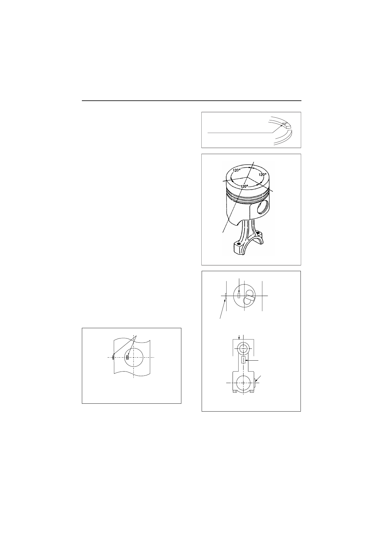
• Install each piston ring on the piston, with the

punched manufacturer’s mark facing upward.

[Reassemble]
• The piston ring joints shall be staggered at by 120°

intervals. Do not position the top ring joint vertical to
the piston pin. The coil expander joint shall be oppo-
site to the oil ring joint.

 [Reassemble]
• When installing the piston pin to the rod and piston,

the punched match mark on the big end of the con-
necting rod shall be opposite to the size mark on the
piston top.

[Reassemble]
• Install the piston in the cylinder clock with the

punched mark on the big end of the rod on the nozzle
side. (The embossed mark at the connecting rod I-
beam section shall be on the flywheel side.)

(R.1)

Make the punched manufacturer's
mark face upward.

Piston ring

Oil ring joint

Ring joints

Expander joint

Top ring joint

Second

ring joint

Piston ID mark

Camshaft side

Nozzle side

Piston ID mark

Embossed mark
(Flywheel side)

Match mark

Cylinder size mark

(Flywheel side)

Assembly direction of connecting
rod and piston

(

)

4TNV106(T)

Assembly direction of connecting
rod and piston

Flywheel side

Engraved mark

Camshaft side

(

)

4.  Disassembly, inspection and reassembly of engines

95

4.4.5 Parts inspection and measurement

(1) Cylinder block

Especially clean head surface, cylinder bores and oil
holes, and check after removing any carbon deposit and
bonding agent.

(a)

Appearance inspection

Check if there is any discoloration or crack. If crack is
suspected, perform color check. Sufficiently clean the oil
holes and check they are not clogged.

(b)Cylinder bore and distortion

Measure at 20 mm below the crest of the liner, at 20 mm 
from the bottom end and at the center.

Roundness:

Roundness is found as follows though it is the simple
method. Measure cylinder diameters of the A direction
and the B direction on each section of a, b and c.
Roundness is the maximum value among those
difference values.

Cylindricity:

Cylindricity is found as follows though it is the simple
method.
Measure cylinder diameters of a, b and c sections in
the A direction, and calculate the difference in
maximum value and minimum value of the measured
diameters.
In the same way measure and calculate the difference
in the B direction.
Cylindricity is the maximum value between those
difference values.

mm

Item

Model

Standard

Limit

Cylinder inside diameter

3TNV82A

82.000 to 82.030

82.200

TNV84

84.000 to 84.030

84.200

TNV88

88.000 to 88.030

88.200

4TNV94L

94.000 to 94.030

94.130

4TNV98

98.000 to 98.030

98.130

4TNV106(T)

106.000 to 106.030

106.130

Cylinder bore

Roundness

all TNV

0.01 or less

0.03

Cylindricity

Cylinder bore

20mm

A

B

Measure in two directions

A and B at points a,b and c.

a

b

c

20mm

Cylinder bore measurement positions

4.  Disassembly, inspection and reassembly of engines

96

(c)If the limit is exceeded or any surface defect is 

found, repair by boring and honing. Use an 
oversized piston (and new piston rings) as 
required.

Oversized piston (0.25 mm, with piston rings)

Piston ring assy for oversized (0.25 mm)

Cylinder dimension after boring and honing

Model

Code No.

Standard (mm)

3TNV82A

719802-22900

82.250

3TNV84 (T)
4TNV84

129004-22900

84.250

4TNV84T

129508-22900

84.250

3/4TNV88

129005-22900

88.250

4TNV94L

729906-22900

94.250

4TNV98

129902-22700

98.250

4TNV106

729907-22900

106.250

4TNV106T

723907-22910

106.250

Model

Piston ring code No.

3TNV82A

719802-22950

3TNV84 (T)
4TNV84

129004-22950

4TNV84T

129004-22950

3/4TNV88

129005-22950

4TNV94L

729906-22950

4TNV98

729907-22950

4TNV106 (T)

723907-22950

Model

Cylinder dimension

(mm)

Honing angle

(deg.)

Surface roughness

Roundness/Cylindricity

(mm)

3TNV82A

82.250 to 82.280

30 to 40 deg.

R

max

1.0 to 3.5S

0.01 or less

3TNV84 (T)
4TNV84

84.250 to 84.280

3/4TNV88

88.250 to 88.280

4TNV94L

94.250 to 94.280

4TNV98

98.250 to 98.280

4TNV106 (T)

106.250 to 106.280

4.  Disassembly, inspection and reassembly of engines

97

(2) Crankshaft

Mainly check seizure and wear of the crankpins and
journals. Since the crankshaft gear is shrink-fitted, heat
to 180 to 200°C when extraction is necessary.

(a)Shaft portion color check

After washing the crankshaft, inspect it by means of
color check or a magnaflux inspector. Replace it if
cracked or heavily damaged. Slight defects shall be
corrected by grinding.

(b)

Crankshaft bend

Support the crankshaft journals at both ends with V-
blocks. Use a dial gage and measure the runout at the
center journal while rotating the shaft to inspect the
bend.

(c)Crankpin and journal measurement

Measure the outside diameter, roundness and taper at
each crankpin and journal.
Correct by grinding if unevenly wear, roundness
exceeding the limit or insufficient outside diameter is
found. Replace if the defect is excessive.

To look for the oil clearance of crank pin, measure the
inside diameter of crank pin metal according to (5) (d)
described later and calculate.

Limit

0.02 mm or less

Item

Limit (Diameter)

 (mm)

Roundness
Taper

0.01

Inspection by color check

Bend

Deflection

Dial gage

V-block

V-block

Crankshaft bend measurement

Measuring position of the crankpin
and crank journal

Crankshaft
journal

Crankpin

4.  Disassembly, inspection and reassembly of engines

98

If the oil clearance exceeds the limit, use an undersized bearing.

Undersized crankpin bearing (0.25 mm)

Pin machining dimension

Crankpin

 mm

Model & Item

Standard

Limit

3TNV82A

Pin outside diameter

42.952 to 42.962

42.902

Metal thickness

1.487 to 1.500

-

Oil clearance

0.038 to 0.090

0.150

TNV84 to 88

Pin outside diameter

47.952 to 47.962

47.902

Metal thickness

1.492 to 1.500

-

Oil clearance

0.038 to 0.074

0.150

4TNV94L•98

Pin outside diameter

57.952 to 57.962

57.902

Metal thickness

1.492 to 1.500

-

Oil clearance

0.038 to 0.074

0.150

4TNV106(T)

Pin outside diameter

63.952 to 63.962

63.902

Metal thickness

1.984 to 1.992

-

Oil clearance

0.054 to 0.090

0.150

Model

Code No.

Standard thickness (mm)

3TNV82A

119810-23610

1.612 to 1.625

TNV84 to 88

129150-23610

1.617 to 1.625

4TNV94L•98

129900-23610

1.617 to 1.625

4TNV106(T)

123900-23610

2.109 to 2.117

Model

Pin machining dimension (mm)

3TNV82A

ø 42.702 to 42.712

TNV84 to 88

ø 47.702 to 47.712

4TNV94L•98

ø 57.702 to 57.712

4TNV106 (T)

ø 63.702 to 63.712

4.  Disassembly, inspection and reassembly of engines

99

If the clearance limit is exceeded, use an undersized bearing.

Undersized bearing (0.25 mm)

Crankshaft Journal machining dimension

Crank journal

 mm

Model

Item

Standard

Limit

3TNV82A

Journal O.D.

46.952 to 46.962

46.902

Metal thickness

1.987 to 2.000

-

Oil clearance

0.038 to 0.080

0.150

TNV84 to 88
(Selective assembly)

Journal O.D.

53.952 to 53.962

53.902

Metal thickness

1.995 to 1.990

-

Oil clearance

0.038 to 0.068

0.150

4TNV94•98
(Selective assembly)

Journal O.D.

64.952 to 64.962

64.902

Metal thickness

1.995 to 2.010

-

Oil clearance

0.038 to 0.068

0.150

4TNV106(T)
(Selective assembly)

Journal O.D.

75.952 to 75.962

75.902

Metal thickness

2.488 to 2.503

-

Oil clearance

0.052 to 0.082

0.150

Model

Code No.

Standard thickness (mm)

3TNV82A

119810-02870

2.112 to 2.125

TNV84 to 88

129150-02870

2.112 to 2.125

4TNV94L•98

129900-02340

2.112 to 2.125

4TNV106 (T)

12900-02340

2.605 to 2.618

Model

Journal machining dimension (mm)

3TNV82A

ø 46.702 to 46.712

TNV84 to 88

ø 53.702 to 53.712

4TNV94/98

ø 64.702 to 64.712

4TNV106 (T)

ø 75.702 to 75.712

4.  Disassembly, inspection and reassembly of engines

100

• Dimension R and finishing precision of crankshaft

journal and pin
As for grinding processing of journal and pin,
machine it by using the grinding wheel of the dimen-
sion R of below table.
Surface finishing precision standard on journal and
pin:
Ry=0.8S super polishing

Surface finishing precision standard on the thrust
side of crankshaft arm:

[NOTICE]

1)If the oil clearance is excessive though the thicknesses of the journal and crankpin metals are normal or if

partial uneven wear is observed, re-grind the crankshaft and use an oversized metals.

2)If rust or surface roughening exists on the rear side of the metals, coat it with blue or minimum. Then

assemble the crankpin metal to the connecting rod, and tighten the rod bolt to the specified torque to
check the metal for contact. If the contact surface occupies 75% or more, the metal is normal. If the con-
tact surface is insufficient, the metal interference is insufficient. Replace the metal with a new one.

(3) Thrust metal inspection

(a)Inspect any damage or wear.
(b)Measure side gap and thrust metal thickness

If the side gap is exceeded, use an oversized thrust metal. (Refer to point 4 of 4.4.4.)

Oversized metal (0.25 mm)

mm

Model

Finishing precision standard 

of dimension R

3TNV82A
3/4TNV84(T) to 88

3.5 +0.3/ 0

4TNV94L/98(T)
4TNV106(T)

4.0 +0.3/ 0

Side gap and thrust metal thickness                                                                   mm

Model

Side gap

Thrust metal thickness

Standard

Limit

Standard

Limit

3TNV82A
3/4TNV84 (T) to 88

0.14 to 0.22

0.28

1.930 to 1.980

1.850

4TNV94L•98

0.13 to 0.23

1.930 to 1.980

1.850

4TNV106 (T)

0.13 to 0.23

2.430 to 2.480

2.35

Model

Code No. (Up-down combination)

3TNV82A

119810-02940

3/4TNV84(T) to 88

129150-02940

4TNV94L to 4TNV106 (T)

129900-02940

Super
polishing

Ry=0.8S

Super
polishing

Thrust

face

Crank Pin

Crankshaft R machining

Crank Journal

Ry=0.8S

R

R

R

R

R

1.6

4.  Disassembly, inspection and reassembly of engines

101

(4) Piston

Especially clean the combustion surface, circumference,
ring grooves and piston pin bosses, and check after
removing any carbon deposit. Any burr at a ring groove
or snap ring groove shall be removed. If crack is
suspected, inspect by color check.

(a)Piston outside diameter measurement

Measure the long diameter at H mm from the bottom end
of the piston of the oval hole in the vertical direction to
the piston pin hole.

Piston outside diameter

If the piston outside diameter exceed the limit, replace the piston with new one. 
If the clearance between piston and cylinder exceeds the limit, use an oversized piston. (Refer to the tables of
oversized pistons, oversized piston rings and cylinder boring dimension in (1) (c) above.)
Selective pairing of cylinder and piston

Piston must be paired with cylinder according to the below table. The size mark of a piston is shown on
the top surface of the piston and the size mark of a cylinder block is shown on the non-operating side of
the cylinder block. The service parts of pistons are provided.

mm

Model

Outside diameter

Standard

Limit

Clearance between

piston and cylinder

Measurement

position (H)

3TNV82A

81.950 to 81.980

81.905

0.040 to 0.060

16 

3,4TNV84(T)

83.940 to 83.970

83.895

0.050 to 0.070

24

3,4TNV88

87.940 to 87.970

87.895

24

4TNV94L

93.935 to 93.965

93.900

0.055 to 0.075

22

4TNV98 (T)

97.930 to 97.960

97.895

0.060 to 0.080

22

4TNV106 (T)

105.930 to 105.960

105.880

30

Piston outside diameter. D2

Tolerance

+0.015 max.
+0.005 min.

below +0.005
0 min.

below 0
-0.005 min.

below -0.005
-0.015 min.

Size mark

L

ML

MS

S

Cylinder 
inside 
diameter

D1

+0.030 max.
+0.020 min.

L

c

c

°

°

below

 +0.020

+0.010 min.

M

°

c

c

°

below

 +0.010

0 min.

S

°

°

c

c

Model

Cylinder inside diameter

D1

Piston outside diameter.

D2

3TNV82A

82

81.965

3,4TNV84 (T)

84

83.955

3,4TNV88

88

87.955

4TNV94L

94

93.950

4TNV98 (T)

98

97.945

4TNV106 (T)

106

105.945

Measurement
position

H mm

Piston outside diameter

4.  Disassembly, inspection and reassembly of engines

102

(b)

Piston pin hole measurement

Measure the outside diameter of piston pin and the
inside diameter of piston pin hole. Calculate the
clearance between piston pin and piston pin hole. If any
data exceeds the limit, replace the part with a new one.

(c)

Piston ring, ring groove and end clearance 

measurement

• Except for the top ring, to measure the piston ring

groove width, first measure the width of the piston
ring. Then insert the piston ring into the ring. Then
insert the piston ring into the ring groove. Insert a
thickness gage in between the piston ring and groove
to measure the gap between them. Obtain the ring
groove width by adding ring width to the measured
side clearance.

• To measure the end clearance, push the piston ring

into the sleeve using the piston head, insert a thick-
ness gage in end clearance to measure. The ring
shall be pushed in to approx. 30 mm above the bot-
tom end of the cylinder. For the top ring, measure
only the piston ring joint end clearance in normal
state.

(R.1)

mm

Model

Item

Standard

Limit

3TNV82A

Pin I.D.

23.000 to 23.009

23.039

Pin O.D.

22.995 to 23.000

22.965

Clearance

0.000 to 0.014

0.074

TNV84 to 88

Pin I.D.

26.000 to 26.009

26.039

Pin O.D.

25.995 to 26.000

25.965

Clearance

0.000 to 0.014

0.074

4TNV94L•
4TNV98 (T)

Pin I.D.

30.000 to 30.009

30.039

Pin O.D.

29.989 to 30.000

29.959

Clearance

0.000 to 0.020

0.080 

4TNV106 (T)

Pin I.D.

37.000 to 37.011

37.039

Pin O.D.

36.989 to 37.000

36.959

Clearance

0.000 to 0.022

0.080

Measure at positions a,b and c
in directions A and B.

A

B

a

b

c

Piston pin outside diameter

Top ring

Top ring

4TNV94L

4TNV106(T)

3TNV82A

3/4TNV88

Second ring

Oil ring

Second ring

Oil ring

Ring components

Ring joint end clearance
measurement

Approx.
30mm

Head surface

Cylinder block

Pistonring

Joint end clearance

Width

Thickness

Measuring side clearance

4.  Disassembly, inspection and reassembly of engines

103

Piston ring dimension

(R.1)

 mm

Model

Part

Item

Standard

Limit

TNV82A/84

Top ring

Ring groove width

2.065 to 2.080

2.170

Ring width

1.970 to 1.990

1.950

Side clearance

0.075 to 0.110

0.200

End clearance

0.200 to 0.400

0.490

Second ring

Ring groove width

2.035 to 2.050

2.150

Ring width

1.970 to 1.990

1.950

Side clearance

0.045 to 0.080

0.200

End clearance

0.200 to 0.400

0.490

Oil ring

Ring groove width

4.015 to 4.030

4.130

Ring width

3.970 to 3.990

3.950

Side clearance

0.025 to 0.060

0.180

End clearance

0.200 to 0.400

0.490

TNV88

Top ring

Ring groove width

2.060 to 2.075

2.170

Ring width

1.970 to 1.990

1.950

Side clearance

0.070 to 0.105

0.200

End clearance

0.200 to 0.400

0.490

Second ring

Ring groove width

2.025 to 2.040

2.140

Ring width

1.970 to 1.990

1.950

Side clearance

0.035 to 0.070

0.190

End clearance

0.200 to 0.400

0.490

Oil ring

Ring groove width

4.015 to 4.030

4.130

Ring width

3.970 to 3.990

3.950

Side clearance

0.025 to 0.060

0.180

End clearance

0.200 to 0.400

0.490

4TNV94L•98

Top ring

Ring groove width

2.040 to 2.060

-

Ring width

1.940 to 1.960

1.920

Side clearance

0.080 to 0.120

-

End clearance

0.250 to 0.450

0.540

Second ring

Ring groove width

2.080 to 2.095

2.195

Ring width

1.970 to 1.990

1.950

Side clearance

0.090 to 0.125

0.245

End clearance

0.450 to 0.650

0.730

Oil ring

Ring groove width

3.015 to 3.030

3.130

Ring width

2.970 to 2.990

2.950

Side clearance

0.025 to 0.060

0.180

End clearance

0.250 to 0.450

0.550

4TNV106 (T)

Top ring

Ring groove width

2.520 to 2.540

-

Ring width

2.440 to 2.460

2.420

Side clearance

0.060 to 0.100

-

End clearance

0.300 to 0.450

0.540

Second ring

Ring groove width

2.070 to 2.085

2.185

Ring width

1.970 to 1.990

1.950

Side clearance

0.080 to 0.115

0.235

End clearance

0.450 to 0.600

0.680

Oil ring

Ring groove width

3.015 to 3.030

3.130

Ring width

2.970 to 2.990

2.950

Side clearance

0.025 to 0.060

0.180

End clearance

0.300 to 0.500

0.600

4. Disassembly, inspection and reassembly of engines

104

(5) Connecting rod

(a)

Appearance inspection

Inspect the portion near the boundary of the chamfered
portion and I-beam section of the big and small ends of
the connecting rod as well as the portion near the oil hole
of the bushing at the small end for cracks, deformation,
and discoloration.

(b)Twist and parallelism measurement Use a 

connecting rod aligner and measure the twist and 
bend.

(c)Rod small end measurement

Measure the pin outside diameter according to 
4.4.5.(4) (a) described above.

If the bushing is to be replaced because the oil clearance
exceeds the limit, use spare part.

mm

Item

Standard dimension

Limit dimension

Twist and
parallelism

0.03 or less

per 100 mm

0.08

mm

Model

Item

Standard

Limit

3TNV82A

Piston pin
I.D. bushing

23.025 to 23.038 23.068

Pin O.D.

22.995 to 23.000 22.967

Clearance

0.025 to 0.043

0.101

TNV84 to 88

Piston pin
I.D. bushing

26.025 to 26.038 26.068

Pin O.D.

25.995 to 26.000 25.967

Clearance

0.025 to 0.043

0.101

4TNV94L•98

Piston pin
I.D. bushing

30.025 to 30.038 30.068

Pin O.D.

29.987 to 30.000 29.959

Clearance

0.025 to 0.051

0.109

4TNV106 (T)

Piston pin
I.D. bushing

37.025 to 37.038 37.068

Pin O.D.

36.989 to 37.000 36.961

Clearance

0.025 to 0.049

0.107

Model

Service part code

3TNV82A

119810-23910

TNV84 to 88

129100-23910

4TNV94L•98 (T)

129900-23910

4TNV106 (T)

123900-23910

Connecting rod
aligner

Twist measurement using
a connecting rod aligner

Cylinder gage

Connecting rod small end

4.  Disassembly, inspection and reassembly of engines

105

(d)Rod big end measurement

Measure the crankpin and bushing according to 
4.4.5.(2) (c) described above.
Calculate the oil clearance of a crank pin metal and a
crank pin from the measured values of the crank pin metal
inner diameter and the crank pin outside diameter.
Replace a crank pin metal if the oil clearance becomes
about the limit dimension of the below table.
Correct by grinding if unevenly wear, roundness
exceeding the limit or insufficient outside diameter is
found. Also use an undersized metal. (Refer to the above
(2) c.)
[NOTICE]

When measuring the inside diameter of the rod big end,
install the crankpin metals in the rod big end not to
mistake the top and bottom of the metals and tighten
the rod bolts by the standard torque.

Tightening torque of rod bolt

Model

Tightening torque

N•m (kgf•m)

Lubricating oil application

(threaded portion, and bearing seat surface)

3TNV82A

37.2 to 41.2

(3.8 to 4.2)

Lube. oil applied

TNV84/88

44.1 to 49.0

(4.5 to 5.0)

4TNV94L/98

53.9 to 58.8

(5.5 to 6.0)

4TNV106 (T)

78.5 to 83.4

(8.0 to 8.5)

Standard of rod big end

mm

Model

Item

Standard

Limit

3TNV82A

Rod I.D. bushing

42.952 to 42.962

42.902

Crankpin O.D.

43.000 to 43.042

-

Metal thickness

1.487 to 1.500

-

Clearance

0.038 to 0.090

0.150

TNV84/88

Rod I.D. bushing

47.952 to 47.962

47.902

Crankpin O.D.

48.000 to 48.026

-

Metal thickness

1.492 to 1.500

-

Clearance

0.038 to 0.074

0.150

4TNV94L/98

Rod I.D. bushing

57.952 to 57.962

57.902

Crankpin O.D.

58.000 to 58.026

-

Metal thickness

1.492 to 1.500

-

Clearance

0.038 to 0.074

0.150

4TNV106 (T)

Rod I.D. bushing

63.952 to 63.962

63.902

Crankpin O.D.

64.016 to 64.042

-

Metal thickness

1.984 to 1.992

-

Clearance

0.054 to 0.090

0.150

Cylinder gage

Rod bushing I.D. measurement

4.  Disassembly, inspection and reassembly of engines

106

(6) Tappet

Mainly check the tappet contact surface with the cam and
push rod. Slight surface defects shall be corrected with an
oilstone.

(a)Tappet stem outside diameter measurement

4.4.6 Cylinder bore correction

1)Slight uneven worn, flawed, etc. shall be corrected by

honing only. If the cylinder is unevenly worn partially,
flawed or otherwise damaged and cannot be repaired
simply by honing, rebore the cylinder first and then
hone. See 4.4.5.(1) (c) for the boring dimension.

2)Items to be prepared for honing
• Flex-Hone

(see No.8 of 4.1.2 in Chapter 4)

• Electric drill
• Honing fluid

(50:50 mixture of lube oil and diesel oil)

mm

Model

Item

Standard

Limit

TNV82A to 88

Tappet
hole I.D.

12.000 to 12.025 12.045

Stem O.D.

11.975 to 11.990 11.955

Clearance

0.010 to 0.050

0.090

4TNV94L•98

Tappet
hole I.D.

12.000 to 12.018 12.038

Stem O.D.

11.975 to 11.990 11.955

Clearance

0.010 to 0.043

0.083 

4TNV106 (T)

Tappet
hole I.D.

14.000 to 14.018 14.038

Stem O.D.

13.966 to 13.984 13.946

Clearance

0.015 to 0.052

0.092

Abnormal contact
surface

Normal contact
surface

Tappet

Tappet stem outside diameter measuremen

Flex-Hone

Electric drill

Lube oil
50%

Diesel oil
50%

Honing fluid

Flex-Hone

Items to be prepared for honing

4.  Disassembly, inspection and reassembly of engines

107

3)Apply the honing fluid to the Flex-Hone and turn the

electric drill at 300 to 1200 rpm. Then insert the Flex-
Hone into the cylinder bore while turning it, and move
it up and down for about 30 sec. to obtain a honing
mark with a cross hatch angle of 30 to 40°.

[NOTICE]

1)Avoid faster revolution than 1200 rpm since it may

cause breakdown.

2)Do not insert or extract the Flex-Hone in stopped state

because the cylinder will be damaged.

4.4.7 Piston pin bushing replacement

Replace bushing by using the special service tool (see 4.1.2 No.3 in Chapter 4).

4.4.8 Oil seal replacement (Flywheel housing side)

1)Replace oil seal, when a flywheel housing is removed. Extract the used oil seal.
2)Insert a new oil seal with the oil seal insertion tool.
3)Apply lithium grease.

30

q

40

q

Honing cross hatch

Service life of cylinder block (H

3

)

(H

3

=3H

1

)

Honing

Increase in L.O.C.
or blow-by

Increase in L.O.C.
or blow-by

Increase in L.O.C.
or blow-by

Increase in L.O.C.
or blow-by

Boring

Honing

Boring and honing interval (H

2

)

(H

2

=1.5H

1

)

Time for honing (H

1

)

Study if an oversized piston or piston ring is usable

5.  Lubrication system

108

5. Lubrication system

5.1 Lubrication system diagram

Note: It varies in the specifications of each model whether Oil cooler, Piston and Turbo charger of the * mark

are attached.

(R.1)

̪

Oil cooler

̪

Piston

Bypass valve

Oil pressure

swich

Intermediate

gear shaft

Regulator

valve

Oil pump

Oil suction pipe

(strainer)

Camshaft

bearing

Rocker arm

bearing

Rocker arm

Tappet

Cam face

Crank pin

Crank

journal

Fuel injection

pump

̪

Turbo charger

Cylinder body 

Main gallery

Oil pan

5.  Lubrication System

109-1

5.2 Trochoid pump components

5.3 Disassembly (Reverse the procedure below for assembly)

1)Loosen the belt, and remove the radiator pulley, fan and V-belt.   See 4.2.2. 2) in Chapter 4.
2)Remove the crankshaft pulley.   See 4.3.2.3) in Chapter 4.
3)Remove the gear case cover.   See 4.3.2. 4) in Chapter 4.
4)Remove the lubricating oil pump assy from the gear case for 4TNV94/98/106. (5.4 Point 1)

Remove the lube oil cover from gear case cover for 3TNV82A-88. (5.4 Point 1)

5)Remove the pressure regulating valve from the lubricating oil pump body. (5.4 Point 2)

5.4 Servicing points

Point 1

[Disassemble]
• Check if the pump rotates smoothly and see that there is no play between the shaft and gear, and inner

rotor.

[Reassemble]
[NOTICE]

Always check if the pump rotates smoothly after installation on the gear case.
Running the engine when the pump rotation is heavy may cause the pump to be burnt.

1)3TNV82A-88
• Apply lube oil to rotor (outer/inner) insertion part.
• Assemble the outer rotor so that the mark of the end face may become a cover side when inserting it in the

gear case.

• Fasten a lube oil pump cover by the standard torque.
• Tightening torque: 6.9 ± 1.5 N•m (0.7 ± 0.15 kgf•m)
• When replacing the lube oil pump, replace the whole assy.
2)4TNV94L/98/106
• Apply lube oil to lube oil pump insertion part of gear case.
• Install the outer rotor in the gear case so that the punch mark on the end face is seen.
• When replacing the lube oil pump, replace the whole assy.

Trochoid pump (3TNV82A to TNV88)

Trochoid pump (4TNV94L/98/106)

Outer rotor

Inner rotor

Control valve

Crankshaft

Pump cover

Gear case

Plug

Outer rotor

Control valve

Gear case

Punch mark

Crankshaft


Content      ..     54      55      56      57     ..