Takeuchi compact excavator TB125, TB135, TB145 / diesel TNE / diesel Yanmar. Service Manual - page 61
 

  Index      Manuals     Takeuchi compact excavator TB125 (12510003~), TB135 (13510004~), TB145 (14510004~) / diesel TNE / diesel Yanmar. Service Manual


Search            copyright infringement  


Content      ..     59      60      61      62     ..


Takeuchi compact excavator TB125, TB135, TB145 / diesel TNE / diesel Yanmar. Service Manual - page 61


9.  Starting motror

172

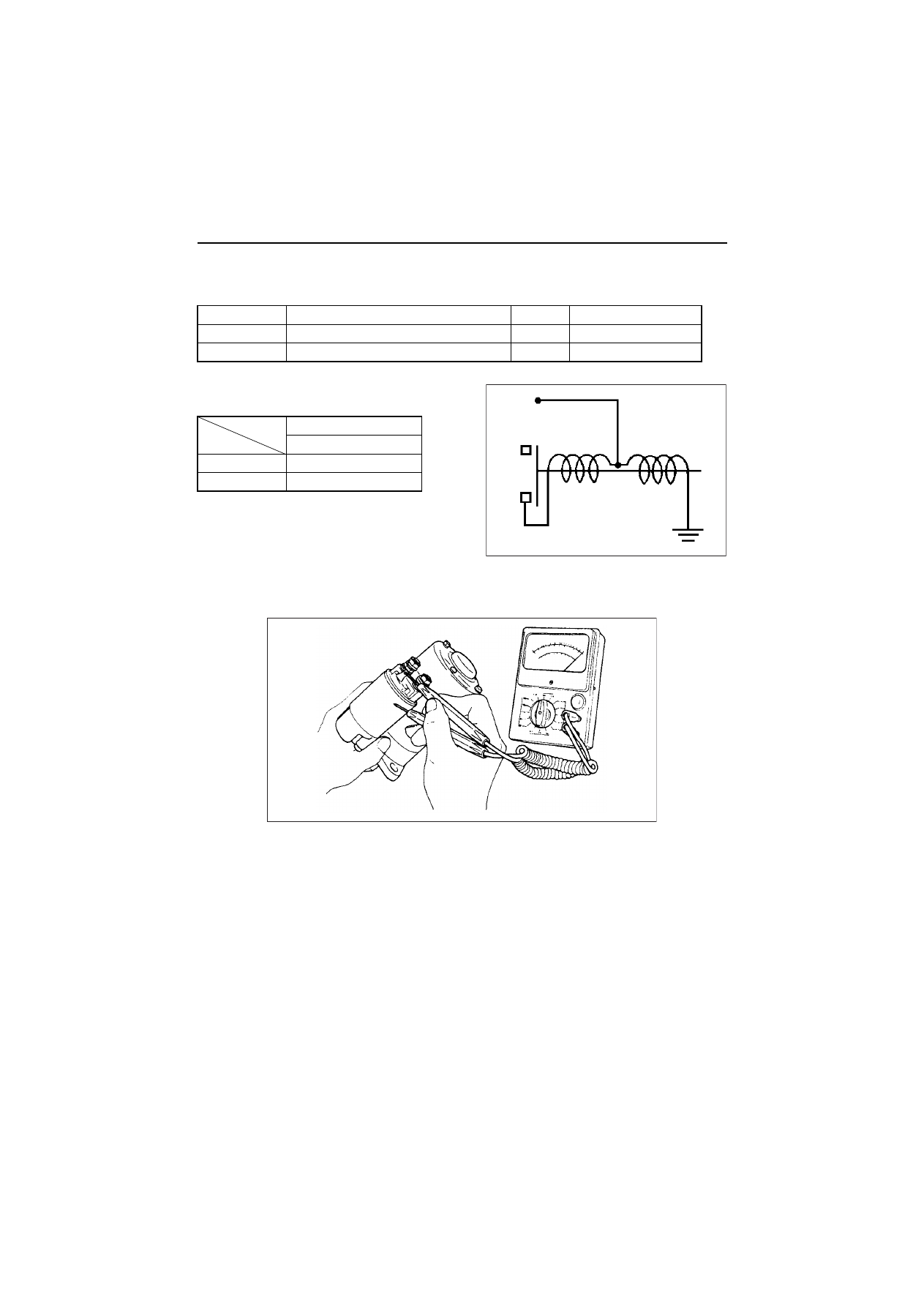
(4) Magnetic switch continuity test

Replace if needed.

Test type

Measurement point

Normal

Abnormal (cause)

Shunt coil

Between C and ground

Yes

None (open circuit)

Series coil

C and M

None

Yes (short-circuiting)

S13-138

Resistance (at 20°C)

Shunt coil

0.6

Series coil

0.218

C

B

M

9.  Starting motror

173

(5) Pinion

1)Check the pinion teeth for wear and damage. Replace with a new one, if necessary.
2)Check if the pinion slides smoothly. If it is damaged or rusted or does not slide smoothly, repair.
3)Check springs for damage, and replace if necessary.

(6) Ball bearing

If abnormalities such as irregular noises are detected to the ball bearing, replace with a new one.

9.2.7 Assembly

The assembly procedure is reverse of the disassembly procedure, but pay attention to the following points.

(1) Apply grease as instructed below.

(2) Armature thrust

No adjustments are needed for the thrust.

(3) Gear shaft thrust

Some thrust washers of 1.0 and 0.25 mm thickness are provided between the center bracket and gear shaft
supporting surface. Make sure to check them at reassembly.
If washers are deformed or worn, replace them with new ones.
The appropriate thrust is from 0.05 to 0.3mm. If it is over 0.3mm, and the appropriate thrust washer, but pay
attention so that the thrust is not 0.

Greasing point

Grease type

Sliding portions and head of plunger 
Pinion metal and metal portions of gear case
Spline portions of pinion
Sliding portions of shift lever

NPC-FC6A Grease

Deceleration gear

MALTEMP SRL Grease

9.  Starting motror

174

9.2.8 Adjustment

(1) Pinion projection length L by magnetic switch

Measure the pinion moving distance L (0.3 to 1.5 mm) in the thrust direction when the pinion is protruded by 
the magnetic switch.
If the distance L is outside the standard range, adjust by the dust cover as shown below.

l

l

Switch

Battery

9.  Starting Motor

175-1

9.2.9 Service standards

Brush

Spring force N (kgf)

31.4 (3.2)

Standard / Limit height

18/6 

Commutator

Outside diameter

Standard

37

Limit

36

Deflection

Limit

0.2

Correction accuracy

0.05

Depth of insulation mica

Limit

0.2

Correction accuracy

0.5 to 0.8

Standard
dimensions

Armature shaft diameter

Front

25

Rear

12

Bearing on gear case side

Gear shaft diameter

13.95 to 13.968

Hole diameter

14.00 to 14.018

Sliding portion of pinion

Shaft diameter

13.95 to 13.968

Hole diameter

14.03 to 14.05

Ball bearing

Armature

Front

6905DDU

Rear

6001DDU

Length L (pinion projection length)

0.3 to 1.5

l

Dust cover

9.  Starting Motor

175-2

9.3 For 3TNV82A to 3/4TNV88

9.3.1 Specifications

9.3.2 Characteristics

(R.1)

Manufacturer’s code (Denso)

-

228000-0251

Yanmar code

-

12912-77010

Nominal voltage

V

12

Nominal output

kW

1.2

Rating

Sec

30

Revolution direction (as viewed from pinion)

-

Clockwise

Engagement system

-

Magnetic shift

Pinion: Number

-

1.3

Weight

kg

3.5

Pinion projection voltage (at 100)

V

8 or less

No-load

Terminal voltage/current

V/A

11.5/90 or less

Revolution

min

-1

3000 or more

Loaded

Terminal voltage/current

V/A

8/280 or less

Torque

N•m (kgf•m)

9.81(1.0)

Revolution

min

-1

900

CURRENT      (A)

STARTER PERFORMANCE

BATTERY  6V-400A
12V   1.2kW

100

200

300

400

500

2.4524.0 1.2 12

6000

2.0520.0 1.0 10

5000

1.6316.0 0.8

8

4000

1.2212.0 0.6

6

3000

0.82 8.0 0.4

4

2000

0.41 4.0 0.2

2

1000

0

0

0

0

0

600

(V)

VOL

T

AGE

(kW)

OUTPUT

(N

m)

T

O

ROUE

(kgf

O

)

T

O

ROUE

 (min

-1

)

REVOLUTION

VOLTAGE

OUTPUT

TORQUE

REVOLUTION

9.  Starting Motor

175-3

9.3.3 Disassembly drawing

9.3.4 Connecting diagram of a starting motor

1)When a starter switch is turned on, a magnet switch

is charged, and a moving core is absorbed, and a
pinion clutch is moved forward through a lever, and
the pinion engages with a ring gear.

2)When the pinion engages the ring gear, because a

main contact point is closed and the main electric
current flows and a pull coil is short-circuited by the
main contact point and it stops being charged with
electricity, the pinion is kept at the position by a hold-
ing coil during the start.

3)When the stater switch is turned off, the main con-

tact point becomes open, and the pinion clutch is
returned to the stop position by a return spring.

(R.1)

Armature

Yoke

Holder

Frame

Switch

Pinion

Housing

Clutch

Pinion

CONNECTING DIAGRAM

STARTER SWITCH

Magnetic switch

Starting motor

Battery

10.  Alternator

176

10. Alternator

As a representative example of alternator, the alternator of 40A is shown in this chapter.

10.1 The 40A alternator for 3TNV84 and other models

10.1.1 Components

(1) Parts related to the alternator

(2) Alternator components of the disassembly and assembly

10.  Alternator

177

10.1.2 Specifications

10.1.3 Wiring diagram

[NOTICE]

1)Don't do miss-wiring and short-circuit of each terminal.
2)Don’t short-circuit between IG and L. (Connect it through the charge lamp.)
3)Don’t connect a load between L and E.
4)Don't remove a battery terminal and a B terminal when rotating.
5)Shut out a battery switch during the alternator stop.
6)Tightening torque of each terminal: 1.7-2.3 N•m (17-23 kgf•cm)

Manufacturer’s model (Hitachi)

-

ACFA68

Yanmar code

-

129423-77200

Rating

-

Continuous

Battery voltage

V

12

Nominal output (13.5 V heat)

A

40

Rated revolution

min

-1

5,000

Operating revolution

min

-1

1,350 to 18,000

Grounding characteristics

-

Minus side grounding

Direction of revolution (viewed from pulley)

-

Clockwise

Integrated regulator IC 

regulator

Weight

kg

2.8

Pulley (outside diameter)

mm

69.2

Belt shape

-

Type A

WIRING DIAGRAM

L

IG

B

P

L

IG

IC

B

F

E

0.5

Ǵ

F

E

PI

P

Key switch

ALTERNATOR ASSY

IC REGURATOR

Charge lamp
(Max. 3.4W)

Battery

L

O

A
D

L

O

A
D

B
A
T

10.  Alternator

178

10.1.4 Standard output characteristics

The standard output characteristics of this alternator are
shown as the right figure.

10.1.5 Inspection

(1) V belt inspection

1)Inspect the matter whether there are not crack, stickiness

and wear on the belt visually.
Check that a belt doesn't touch the bottom part of the pul-
ley groove. If necessary, replace the V belt set.

2)V belt tension:

Push the center of the V belt and check the belt deflec-
tion. The V belt tension is normal if the deflection is within
the standard. If not, adjust the V belt tension by the alter-
nator adjuster.
(Refer to 2.2.2 in Chapter 2.)

(2) Visual check of wiring and check of unusual sound

1)Confirm whether wiring is right or there is no looseness of the terminal part.
2)Confirm that there is no unusual sound from the alternator during the engine operation.

(3) Inspection of charge lamp circuit

1)Move a start switch to the position of on. Confirm lighting of the charge lamp.
2)Start an engine, and confirm the lights-out of the lamp. Repair a charge lamp circuit when a lamp doesn't

work.

STANDAED CHAEACTERISTICS

ALTERNATOR SPEED (X10

3

 min

-1

)

OUTPUT

 CURRENT

(A)

13.5V CONSTANT
AMBIENT TEMP:25

͠

Cold

Hot

60

50

40

30

20

10

0      1     2    3     4    5     6     7     8

Normal

Clearance

Inspection of V pulley

Defect

10.  Alternator

179

10.1.6 Troubleshooting

T

u

rn key switch to ON.

Does the charge lamp

come ON?

Does the charge lamp

goes OFF?

Does the charge lamp

come ON?

Ground L-terminal of the

driven machine side coupler

(L, IG).

Does the charge lamp

come ON?

Does the charge lamp

come ON?

T

u

rn the key switch to ST

AR

T

.

(The engine starts.)

ON

At idling

OFF

OFF

OFF

OFF

ON

ON

OFF

ON

Disconnect GN coupler

(L, IG)

Increase the engine speed to

1500 rpm and turn the light

switch to ON.

Measure VB at BA

T

 terminal

with the engine running at

1500 rpm

̪

 Remarks

1) Use a fully charged battery

2) DC voltmeter: 0 to 30 V

, 0.5 class

3) 

The check method is also applicable to

    the bench test

Explanation on abbreviations:

GN : 

Alternator

IC-RG 

: IC regulator

VB 

: BA

T

 terminal voltage

VL :L-terminal 

voltage

Measure VB and VL

 at

BA

T

 L-terminal during

idling

T

u

rn the light switch

to ON during idling

Replace the charge lamp

The charge lamp is available from

the driven machine manufacturer

.

The lamp flashes

VB = 13

15

VB > 15.5

VB - VL

 > 0.5V

VB - VL

 < 0.5V

The lamp is lit

dimly

The lamp is lit

dimly

Inspect the rotor coil and

brush IC-RG

Excessive voltage drop between

BA

T

 and batt ( +  side) terminal

L-terminal defective conduction

Inspect the diode ( -  side)

Replace IC-RG

Inspect the auxiliary diode

Not abnormal

Inspect or replace the fan belt,

and inspect the alternator

Inspect the diode ( +  side)

11. ELECTRIC WIRING

181

11.2 Precaution on electric wiring

11.2.1 Alternator

In the cases listed below the warranty shall not be deemed to apply. Please be sure to read these conditions
carefully when planning to use it with other equipment. Also be certain to give appropriate guidance on usage
to the user.

(1) When the battery cable can be connected backwards

The alternator diode will be damaged and recharging made impossible if the plus and minus ends of the
battery cable are confused. The stator coil will also be burned as a result. To prevent this, supply the user with
a cable of such a length or structure that the plus and minus ends cannot be confused. Also warn the user not
to connect the cable backwards.

(2) When charging output voltage is used for control purposes

The engine speed at starting is not proportional to the output voltage of the alternator, so this output voltage 
must not be used for any control systems. It is especially wrong to use it for the control signal of the safety 
relay for cutting the starter motor because this will damage the starter motor and cause engine starting failure.

(3) When the L line is used for control purposes

Consult with Yanmar first before connecting any load other than the charge lamp to the L line. Damage to the
alternator and related equipment will not be warranted without such prior consultation.

(4) Non-use of the Yanmar wiring diagram

Use without prior consultation of any wiring diagram other than that provided by Yanmar removes any
breakdown of any electrical equipment from the warranty.

(5) Regarding lamp control

Once the charge lamp goes out after the start of charging, it does not come on again even if the engine speed 
falls and charging is insufficient. The lamp will not light again if the charging circuit is normal. The lamp only 
comes on during operation if the alternator itself is broken or the drive V-belt breaks. However, when an LED 
is used for the charge lamp, the LED will shine faintly even during normal operation. This is due to the control 
system for the alternator lamp and is not an abnormality.

(6) Use of a non-specified V-belt

Use of a non-specified V-belt will cause inadequate charging and shorten the life of the belt. Use a belt of the
specified type.

(7) Direct high pressure washing is prohibited

Water will enter the brush if the alternator is washed directly at high pressure, causing inadequate charging. 
Warn users not to use direct, high-pressure washing.

(8) Use of agricultural or other chemicals (direct contact or airborne)

Adhesion of agricultural and other chemicals, especially those with high sulfur content, to the IC regulator
corrodes the conductor on the substrate, leading to over-charging (battery boiling) and charging malfunctions.
Consult with Yanmar prior to use in such an environment. Use without prior consultation removes any
breakdown from the warranty.

11. ELECTRIC WIRING

182

11.2.2 Starter

In the cases listed below the warranty shall not be deemed to apply. Please be sure to read these conditions 
carefully when planning to use it with other equipment. Also be certain to give appropriate guidance on usage 
to the user.

(1) Starting performance in the case of using an untested battery

The starting performance of the engine is closely dependent on the battery capacity. This battery capacity is
itself affected by the climate and the type of equipment installation. The details regarding ambient temperature
and equipment installation vary depending on the OEM, so Yanmar cannot decide the battery capacity on its
own. Confer with Yanmar in advance after checking these conditions and fix the battery capacity on the basis
of confirmatory tests.

(2) When the resistance of the battery cable exceeds the specified value

The combined total resistance of the battery cable in both directions between the starting motor and battery
should be within the value indicated on the wiring diagram. The starting motor will malfunction or break down
if the resistance is higher than the specified value.

(3) When the resistance of the starter circuit exceeds the specified value

The combined total resistance of the wiring between the starting motor and key switch (or power relay or
safety relay, depending on the application) should be within the value indicated on the wiring diagram. Engine
starting will be difficult if the resistance is higher than the specified value. This can also cause welding of the
magnet switch at the point of contact and resultant burning of the armature coil.

(4) When there is no safety relay

Over-running (when the electric current flows for too long) is a major cause of starting failure. This burns the
armature coil and causes clutch failure. Excessive work and failure of the key switch to return properly are the
main causes of over-running. The user must be given sufficient warning about this.
Be sure to use the safety relay to prevent over-running. This safety relay is supplied as an option. Consult
Yanmar first when planning to install a safety relay at your own company. In the case of failure to consult with
Yanmar, our warranty will not be applied to all the electrical equipment.

(5) When there is too much rust due to the entry of water

The water-proofing of the starting motor is equivalent to R2 of JIS D 0203. This guarantees that there will be 
no damage from the sort of exposure encountered in rain or when water is poured on from a bucket. You 
should, however, avoid the use of high-pressure washing and steeping in water.

(6) Regarding the heat resistance of the starter motor

The starter motor has heat resistance for an ambient temperature of 80°C and surface temperature of 100°C.
Insulators must be installed to prevent overheating when used near high temperature parts such as the
exhaust system.

(7) Corrosion of magnet switch contact point by corrosive gas. 

When using equipment with a dry clutch, ammonium gas generated by friction is liable to corrode the contact
of the magnet switch. Be sure to install a vent in the clutch case.   

11. ELECTRIC WIRING

183

11.2.3 Current limiter

In the cases listed below the warranty shall not be deemed to apply. Please be sure to read these conditions 
carefully when planning to use it with other equipment. Also be certain to give appropriate guidance on usage 
to the user.

(1) When an over-discharged battery is used

Use of booster starting with an over-discharged battery (when the voltage has dropped to 8 V or less) will
destroy other electrical equipment by generating an abnormally high voltage. A specialized battery charger
should be used to recharge such an over-discharged battery (when the voltage has dropped to 8 V or less).

(2) When checks for malfunctioning are not performed

When high voltage noise from other electrical equipment is impressed on the current limiter upon turning off
the key switch, the current limiter can be damaged and cause loss of control over the output voltage. Other
electrical equipment may also be damaged if this happens, so surge killers should be fitted to the electrical
equipment whenever necessary. Be sure to check prior to mass production whether electrical noise might
damage the current limiter by turning the key switch and other electrical equipment on and off while the
engine is running, using both the vehicle and the wire harness that will be used in mass production.   

(3) Removal of the battery cable during operation

The current limiter may malfunction if the battery cable and/or battery are removed during operation,
depending on the kind of electrical equipment being used, causing loss of control over the output voltage. In
such cases, the current limiter and other electrical equipment will be damaged by the generation of a
continuous high voltage of 24-43 V (for 5,000 rpm dynamo). All electrical equipment falls outside the scope of
the warranty under these circumstances. Be sure to warn the user not to remove the battery cable and/or
battery during operation.

(4) If the battery cable can be attached in reverse

The current limiter’s SCR diode will be destroyed if the plus and minus ends of the battery cable are
connected the wrong way around. This causes charging malfunctioning and burns the harness. Give the user
a cable of such a length that it cannot be connected the wrong way and warn the user against connecting the
cable backwards.

(5) Non-use of the Yanmar wiring diagram

Use without prior consultation of any wiring diagram other than that provided by Yanmar removes any
breakdown of any electrical equipment from the warranty.

(6) Installation environment

Observe the following when installing the current limiter:

1)Do not install it on the engine.
2)Place it in a well-ventilated place with an ambient temperature of 65 °C or less.
3)Ensure that the cooling air flows in the right direction for the current limiter’s cooling fins.
4)Do not use the earth wire of the current limiter to earth any other electrical equipment.

11. ELECTRIC WIRING

184

11.2.4 Section area and resistance of electric wire

(1) Allowable maximum cable length 

Terminal resistance is not included.

Note1) Allowable maximum resistance of Battery cable
Note2) Allowable maximum resistance of Starting motor circuit

(2) Terminal resistance

Generally, a terminal resistance is 15 m

 per coupler and 0 

 per screw setting. This resistance should be

included in allowable maximum resistance when the cable length is planned.

Cable size

mm

2

Cable construction

Resistance

(

/m)

2 m

 Note1

(m)

20 m

 Ref.

(m)

50 m

 Note2

(m)

Element No. 

Cable dia.

3

41

ø 0.32

0.005590

0.36

3.58

8.94

5

65

ø 0.32

0.003520

0.57

5.68

14.20

8

50

ø 0.45

0.002320

0.86

8.62

21.55

15

84

ø 0.45

0.001380

1.45

14.49

36.23

20

41

ø 0.80

0.000887

2.25

22.55

56.37

30

70

ø 0.80

0.000520

3.85

38.46

96.15

40

85

ø 0.80

0.000428

4.67

46.73

116.82

50

108

ø 0.80

0.000337

5.93

59.35

148.37

60

127

ø 0.80

0.000287

6.97

69.69

174.22

85

169

ø 0.80

0.000215

9.30

93.02

232.56

100

217

ø 0.80

0.000168

11.90

119.05

297.62

12.  Service standards

185-1

12. Service standards

12.1 Engine tuning

No.

Inspection item

Standard

Limit

Reference

page

1

Gap at intake/exhaust valve heads

mm

TNV82 to A98

0.15 to 0.25

-

2.2.6.(4)

4TNV106(T)

0.25 to 0.35

-

2

V-belt tension

mm

at 98N (10 kgf)

Between alternator 
and crank pulley

Used part

10 to 14

-

2.2.2.(2)

New part

8 to 12

-

Between alternator 
and radiator fan

Used part

7 to 10

New part

5 to 8

Between radiator fan
and crank pulley

Used part

9 to 13

New part

7 to 11

3

Fuel injection 
pressure

MPa (kgf/cm

2

)

3TNV82A to TNV88(VM)
4TNV94L to 106(T)

21.57 to 22.55

(220 to 230)

-

2.2.6.(3)

3TNV82A to TNV88(CL)

19.6 to 20.6

(200 to 210)

4

Compression
pressure

(at 250 min

-1

)

MPa (kgf/cm

2

)

TNV82A

3.16 (31) ± 0.1 (1)

2.45(25) ± 0.1(1)

3.3

TNV84

3.24 (33) ± 0.1 (1)

2.55(26) ± 0.1(1)

3/4TNV84T

2.94 (30) ± 0.1 (1)

2.45(25) ± 0.1(1)

TNV88-106

3.43 (35) ± 0.1 (1)

2.75(28) ± 0.1(1)

5

Coolant water
Capacity
(Only engine 
body)

(Liter)

3TNV82A, 84

1.8

-

2.2.1.(4)

3TNV84T, 88

2.0

-

4TNV84(T), 88

2.7

-

4TNV94L•98(T)

4.2

-

4TNV106(T)

6.0

-

6

Lubricating oil
capacity
(oil pan)

(Liter)

-

Full

Effective

-

2.2.1.(3)

3TNV82A

5.5

1.9

-

3TNV84(T)/88

6.7

2.8

-

4TNV84(T)/88

7.4

3.4

-

4TNV94L/98(T)

10.5

4.5

-

4TNV106(T)(CL class)

14.0

9.0

-

4TNV106(T)(VM class)

14.0

7.5

-

12.  Service standards

185-2

(R.1)

No.

Inspection item

Standard

Limit

Reference

page

7

Lubricating oil
pressure

MPa (kgf/cm

2

)

at lube oil 
temperature 
80 deg.C 
for 3TNV82A-
4TNV98(T) 

100 deg.C for 
4TNV106(T)

-

Rated speed

at rated speed

at low idle speed

-

3TNV82A

1500

2700rpm

0.392(+0.098/-0.049)

(4.0(+1.0/-0.5))

0.06 (0.6)

or above

5.6

2800~3000rpm

0.441(+0.098/-0.049)

(4.5(+1.0/-0.5))

3TNV84

1500~1800rpm

0.392(+0.098/-0.049)

(4.0(+1.0/0.5))

2000~3000rpm

0.441(+0.098/-0.049)

(4.5(+1.0/-0.5))

3TNV88

1500~1800rpm

0.392(+0.098/-0.049)

(4.0(+1.0/0.5))

2000~3000rpm

0.441(+0.098/-0.049)

(4.5(+1.0/-0.5))

3TNV84T

1500~1800rpm

0.343(+0.098/-0.049)

(3.5(+1.0/0.5))

2400~2700rpm

0.392(+0.098/-0.049)

(4.0(+1.0/0.5))

2800~3000rpm

0.441(+0.098/-0.049)

(4.5(+1.0/-0.5))

3TNV84

1500~1800rpm

0.392(+0.098/-0.049)

(4.0(+1.0/0.5))

2000~3000rpm

0.441(+0.098/-0.049)

(4.5(+1.0/-0.5))

4TNV88

1500~1800rpm

0.392(+0.098/-0.049)

(4.0(+1.0/0.5))

2000~3000rpm

0.441(+0.098/-0.049)

(4.5(+1.0/-0.5))

4TNV84T

1500~1800rpm

0.343(+0.098/-0.049)

(3.5(+1.0/0.5))

2000~3000rpm

0.412(+0.098/-0.049)

(4.2(+1.0/0.5))

4TNV94L

1500~2500rpm

0.34(+/0.05) (3.5(+/0.5))

4TNV98

1500~2500rpm

0.34(+/0.05) (3.5(+/0.5))

4TNV98T

1500~2500rpm

0.34(+/0.05) (3.5(+/0.5))

4TNV106

1500~1800rpm

0.44(+0.05/0.10)

(4.5(+0.5/-1.0))

2000~2500rpm

0.44(+/0.05) (4.5(+/0.5))

4TNV106T

1500~1800rpm

0.44(+0.05/-0.10)

(4.5kgf/.cm

2

(+0.5/-1.0))

2000~2200rpm

0.44(+/0.05) (4.5(+/0.5))

8

Oil pressure switch operating pressure

MPa (kgf/cm

2

)

0.05 ± 0.01

(0.5 ± 0.1)

-

-

9 Thermostat 

valve opening 

temperature

deg. C

Full opening lift 

(mm)

(temperature)

2.7

All models

69.5 to 72.5

8 or above
(85 deg.C)

All models
option

80 to 84

10 or above

(95 deg.C)

10

Thermo switch actuating temperature           
(deg.C)

107 to 113

-

2.4.2


Content      ..     59      60      61      62     ..