Takeuchi compact excavator TB125, TB135, TB145 / diesel TNE / diesel Yanmar. Service Manual - page 34
 

  Index      Manuals     Takeuchi compact excavator TB125 (12510003~), TB135 (13510004~), TB145 (14510004~) / diesel TNE / diesel Yanmar. Service Manual


Search            copyright infringement  


Content      ..     32      33      34      35     ..


Takeuchi compact excavator TB125, TB135, TB145 / diesel TNE / diesel Yanmar. Service Manual - page 34


IV-212

HYDRAULIC UNITS

SLEW MOTOR

TB125, 135, 145

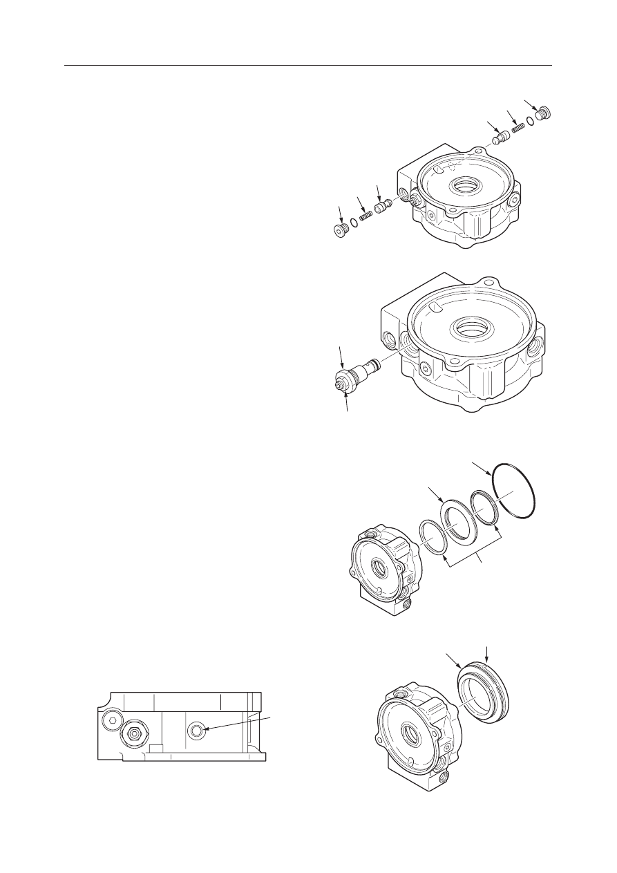
4. Remove the check valve.

a. Remove the plug (9).
b. Remove the spring (10) and check valve (11).

5. Loosen the plug (12) and remove the relief valve.

• Do not loosen the set screw nut (13).
• Do not disassemble the relief valve.

6. Remove the O-ring (14), disc spring (15) and

spring sheet (16).

7. Remove the brake piston (17).

• Blow the air from the brake release port PB

with care such that the brake piston does not
protrude.

PB

E5D619

9

9

10

10

11

11

E5D615

12

13

E5D616

15

14

16

E5D617

17

B

E5D618

IV-213

HYDRAULIC UNITS

SLEW MOTOR

TB125, 135, 145

8. Remove the cylinder block (18) and the disc (19).

9. Remove the shoe holder (20) and the piston

assembly (21) from the cylinder block.

10. Remove the guide (22) and pins (23) from the

cylinder block.

11. Remove the snap ring (24), retainer (25), spring

(26) and retainer (27) from the cylinder block.
• The snap ring should be removed while push-

ing the retainer (25).

12. Remove the swash plate (28).

13. Remove the shaft (29).

• Lightly tap the end face with a plastic hammer.

18

19

E5D620

20

21

22

23

E5D621

E5D622

A

24

25

26

27

18

E5D623

28

A

29

IV-214

HYDRAULIC UNITS

SLEW MOTOR

TB125, 135, 145

14. Disassemble the timer valve.

a. Remove the plug (30).
b. Remove the spring (31), washer (32) and spool

(33).

c. Remove the sleeve (34).

Reduction Gears

1. Remove the O-ring (1) and drive gear (2).

2. Remove the thrust plate (3), planetary gear (4),

needles (5), inner race (6) and thrust washer (7)
from the carrier (8).

3. Remove the carrier (8).

4. Remove the collar (9) and plate (10).

5. Remove the shaft (11).

• Be careful not to miss the shaft.
• If the shaft will not come out easily, lightly tap

it with a plastic hammer.

• To replace the taper roller bearing or collar, the

case assembly should be replaced.

E5D624

30

31

32

33

34

E5D625

8

2

6

3

5

7

4

1

E5D626

9

10

E5D627

11

IV-215

HYDRAULIC UNITS

SLEW MOTOR

TB125, 135, 145

Assembly

Brake Valve and Hydraulic Motor

1. Mount the relief valve assembly.

• Tighten the plug (12).
• Plug tightening torque:

157 

±

10 N·m (16 

±

1 kgf·m)

2. Install the check valve (11) and the spring (10) in

the housing.

3. Fit the O-ring to the plug (9) and mount them on

the cover.
• Plug tightening torque:

39.2 

±

2 N·m (4.0 

±

0.2 kgf·m)

4. Assemble the timer valve.

a. Fit the O-rings to the sleeve (34) and install

them in the housing.

b. Fit the spool (33), washer (32) and spring (31)

into the sleeve hole.

c. Mount the plug (30).

• Plug tightening torque:

84 

±

5 N·m (8.5 

±

0.5 kgf·m)

5. Mount the retainer (27), spring (26), retainer (25)

and snap ring (24) on the cylinder block (18).
• The snap ring should be mounted while push-

ing the retainer (25).

• Position the retainer (27) so that the tapered

(A) side faces the cylinder block.

12

13

E5D616

9

9

10

10

11

11

E5D615

E5D624

30

31

32

33

34

E5D622

A

24

25

26

27

18

IV-216

HYDRAULIC UNITS

SLEW MOTOR

TB125, 135, 145

6. Mount the pins (23) on the cylinder block.

• Apply grease to the pins.

7. Mount the guide (22).

8. Fit the piston assembly (21) to the shoe holder

(20) and mount them on the cylinder block.
• Apply the hydraulic oil to the rotation section.

9. Press fit the shaft (29) in the housing.

10. Install the swash plate (28) in the housing.

• Apply grease to side A of the swash plate.

11. Install the cylinder block (18) and disc (19) in the

housing.
• Be sure to position the pin (23) correctly.

12. Fit the O-rings to the brake piston (17) and install

them in the housing.
• Position the pin hole (B) as shown in the figure.

20

21

22

23

E5D621

E5D623

28

A

29

18

19

E5D620

17

B

E5D618

IV-217

HYDRAULIC UNITS

SLEW MOTOR

TB125, 135, 145

13. Install the spring sheet (16) and disc spring (15) in

the housing.

14. Fit the O-ring (14) to the housing.

15. Fit the pins (8), bearing (6) and O-rings (7) to the

cover.
• Apply grease to the pins.

16. Fit the pin (5) and valve plate (4) to the cover.

• Apply grease to the rear surface (cover side) of

the valve plate to prevent the plate from drop-
ping off.

17. Mount the cover (3) on the housing and fix it with

the cap screws.
• Be careful not to miss the pin and valve plate.
• Cap screw tightening torque:

128 

±

7 N·m (13.1 

±

0.7 kgf·m)

Reduction Gears

1. Put grease into the inner race of the taper roller

bearing.
• Grease type: Shell ALVANIA Grease
• Grease volume: 17~20 mL

E5D628

15

16

16

15

14

16

E5D617

4

5

6

7

8

E5D614

E5D613

3

E5D629

IV-218

HYDRAULIC UNITS

SLEW MOTOR

TB125, 135, 145

2. Install the shaft (11) in the housing.

3. Mount the collar (9) and plate (10).

4. Mount the carrier (8).

5. Mount the thrust washer (7), inner race (6), needles

(5), planetary gear (4), thrust plate (3) and drive
gear (2) on the carrier (8).
• The largely-rounded side of the thrust plate

circumference should face the planetary gear.

6. Fit the O-ring (1) to the case.

E5D631

3

R

4

E5D627

11

E5D626

9

10

E5D630

8

E5D625

8

2

6

3

5

7

4

1

IV-219

HYDRAULIC UNITS

SLEW MOTOR

TB125, 135, 145

Slew Motor

1. Unite the hydraulic motor (1) and the reduction

gear (2) and fix them with the cap screws.
• Cap screw tightening torque:

128 

±

7 N·m (13.1 

±

0.7 kgf·m)

E5D612

1

2

IV-220

HYDRAULIC UNITS

SLEW MOTOR

TB125, 135, 145

INSPECTION AND ADJUSTMENT

Checking the Parts

Brake Valve

Hydraulic Motor

Parts

Judgement Criteria

Treatment

Check Valve,
Piston

Housing

Relief Valve
Assembly

Spring

• Scratches in sliding portions are deep or roughness is severe.
• The clearance with the body is large.
• Scratches in sliding portions are deep or seating is uneven.
• Scratches in sliding portions are deep or roughness is severe.
• There are scratches where oil leakage occurs.
• The set pressure drops abnormally low.
• The set pressure is unstable and vibration occurs.
• There is a lot of leakage due to faulty seating, etc.
• Damaged or severely deformed.

• Replace
• Replace
• Replace
• Replace
• Replace
• Replace
• Replace
• Replace
• Replace

Parts

Standard

Dimension

Recommended

Replacement

Value

Treatment

Clearance (S) be-
tween piston and
cylinder bore

Clearance (S) be-
tween piston and
shoe

Bearing

Cylinder block
sliding surface (1)

0.02mm

Replace cylinder
block, swash plate
assembly.

Replace cylinder
block, swash plate
assembly.

Replace

Carry out lap re-
pairs (#1000 Pow-
der) or replace.

Replace

0.04mm

0.4mm

Flaking or pitting
in the rolling sur-
face.

Sliding surface is
rough.

0.15mm

E5D632

d

S=D-d

D

E5D633

S

E5D635

2

1

Valve plate sliding
surface (2)

IV-221

HYDRAULIC UNITS

SLEW MOTOR

TB125, 135, 145

Reduction Gears

Parts

Judgement Criteria

Treatment

Drive Gear

Housing,
Internal Gear
Planetary Gear

Needle Bearing,
Planetary Shaft

Carrier, Shaft
Shaft
Thrust Wasyer
Ball Bearing,
Roller Bearing

Collar, Oil Seal,
O-ring

• Gear tooth surfaces are pitted or separating, etc.
• Clearance with motor joint is large due to spline wear.

• Gear tooth surfaces are pitted or separating, etc.

• Gear tooth surfaces are pitted or separating, etc.
• Needle rolling surfaces are pitted or separating, etc.
• Needle and shaft rolling surfaces are pitted or separating, etc.
• Pressure marks, etc. on needle and shaft rolling surfaces.
• Bearing rotation is abnormal (abnormal noise, rotation not smooth,

etc.).

• Clearance with planetary shaft is large.
• Clearance with pinion is large due to spline wear.
• Amount of wear is great.
• Rotation is abnormal (abnormal noise, rotation not smooth, etc.).
• Flaking, separation, etc. on rolling surfaces.
• Pressure marks, etc. on rolling surfaces.
• Scratches, etc. exist which cause leaks.

• Replace
• Replace

• Replace

• Replace
• Replace
• Replace
• Replace
• Replace

• Replace
• Replace
• Replace
• Replace
• Replace
• Replace
• Replace

Brake Valve

Adjusting the Relief Valve Pressure

“II, Specifications, Performance Judgment Stan-
dards”

IV-222

HYDRAULIC UNITS

SLEW MOTOR

TB125, 135, 145

TROUBLESHOOTING

If there is an abnormal increase in noise or heat, this
is an indication that trouble has occurred. When this
type of condition is manifested, stop the machine
immediately and search out the source of the trouble.

The following table shows a number of causes of
general breakdowns that can be seen in the hydraulic
circuits and indicates coutermeasures to take in each
case.

Symptom

How/Where?

Probable Causes

Remedy

Motor does not start.

Motor’s speed won’t
increase.

Oil is leaking.

Motor makes abnor-
mal noise.
(The surface tempera-
ture of the reduction
gears case becomes
high.)

Pressure doesn’t rise at the
motor’s inlet port.

Pressure rises at the motor’s
inlet port.

• Pump’s discharge vol-

ume is insufficient.

• Depends on the motor’s

function.

• Oil is leaking from oil

seals.

• Oil is leaking from mat-

ing surfaces.

• Noise in piping.

• Lubricating oil

• Gear unit

• Relief valve’s set pressure

is low.

• Pump is broken down.

• Control valve is broken

down.

• The load is excessive.
• Hydraulic motor is broken

down.

• Reduction gears are bro-

ken down.

• Pump’s drain amount is

large.

• The motor’s volumetric ca-

pacity is dropping.

• Lip is cut or damaged.

• Bolts are loose.
• O-ring is cut or damaged.
• Mating surface is scratched.

• Piping support is faulty.

• Oil level is low.
• Hydraulic oil is getting in.
• Bearings are damaged.
• Gear surfaces are damaged.

• Set the pressure at the cor-

rect level.

• Repair or replace the

pump.

• Repair or replace the con-

trol valve.

• Lighten the load.
• Repair or replace the hy-

draulic motor.

• Repair or replace the re-

duction gears.

• Repair or replace the

pump.

• Replace the motor.

• Replace the oil seal.

• Tighten the bolts.
• Replace the O-ring.
• Repair the surface with a

grind stone or sand paper.

• Clamp the piping.

• Replenish the oil.
• Replace the reduction gears.

IV-223

HYDRAULIC UNITS

SLEW MOTOR

TB125, 135, 145

SLEW MOTOR (TB135)

CONSTRUCTION

Hydraulic Motor

G4D600

16

23

19

9

13

27

20

6

15

22

8

17

24

12

10

14

18

11

7

26

3

4

2

21

1

5

25

  1. O-ring
  2. O-ring
  3. O-ring
  4. O-ring
  5. Disc
  6. Cylinder Block
  7. Brake Piston
  8. Spring
  9. Shaft

10. Retainer
11. Disk Spring
12. Retainer
13. Guide
14. Pin
15. Valve Plate
16. Bearing
17. Snap Ring
18. Spring Seat

19. Shoe Holder
20. Pin
21. Orifice
22. Pin
23. Swash Plate
24. Bearing
25. Housing
26. Cover
27. Piston

IV-224

HYDRAULIC UNITS

SLEW MOTOR

TB125, 135, 145

  1. Plate
  2. Oil Seal
  3. Shaft
  4. Collar
  5. Bearing
  6. Housing
  7. Bearing
  8. Plate
  9. Collar

Reduction Gears

G4D601

6

17

10

11

12

13

14

19

21

22

18

23

24

25

3

4

1

5

2

7

9

8

20

16

26

15

10. Carrier
11. Thrust Washer
12. Race
13. Needle
14. Planetary Gear B
15. Plate
16. Drive Gear
17. O-ring
18. O-ring

19. Screw
20. Sun Gear
21. Carrier 1
22. Thrust Washer
23. Race
24. Needle
25. Planetary Gear A
26. Thrust Plate

IV-225

HYDRAULIC UNITS

SLEW MOTOR

TB125, 135, 145

  1. O-ring
  2. Poppet
  3. O-ring
  4. O-ring
  5. Backup Ring
  6. O-ring
  7. O-ring
  8. O-ring
  9. Backup Ring
10. Sleeve
11. Seat
12. Seat

Brake Valve

13. Spring
14. Plug
15. Piston
16. Spring
17. O-ring
18. Sleeve
19. O-ring
20. O-ring
21. O-ring
22. Spool
23. Washer
24. Spring

A: Relief Valve
B: Timer Valve
C: Check Valve
D: Anti-rebound Valve

25. Body
26. Check Valve Assembly
27. Spring
28. Sleeve
29. Orifice
30. O-ring
31. Body
32. O-ring
33. Filter
34. Washer
35. Orifice

G4D602

19

20

21

22

18

8

24

23

B

17

A

C

16

7

D

25

28

26

27

30

29

30

11

10

15

5

4

14

9

6

2

12

13

1

3

35

34

33

32

31

IV-226

HYDRAULIC UNITS

SLEW MOTOR

TB125, 135, 145

OPERATION

hydraulic motor

“IV-208”

Relief Valve

“IV-208~209”

Anti-rebound Valve

When the motor stops, this valve will connect the
motor main circuit to the makeup circuit for a pre-
scribed time to prevent motor rebound due to the
pressure in the main circuit.

When the Brake is Actuated
The braking pressure generated at the port Pv1 will
move the check valve (2) to the right until it is seated
at section B.

When the Motor Rebounds
When the motor is stopped by braking operation of the
brake valve, it starts to rebound due to the pressure in
the main circuit. This rebound pressure generated at
the port Pv2 will move the sleeve (3) to the left to open
the passage. This then releases the rebound pressure
to the port Cv.

The rebound pressure also pushes the check valve (1)
to the left, which is the opposite direction of pushing
at the time of braking. The flux control valve built in
the check valve (2) (that is now on the lower pressure
side) releases the oil in the damper chamber (4) at a
constant flux. Therefore, the check valve (1) moves at
a constant speed. When the check valve reaches its
stroke end, the passage from the port Pv2 to the port
Cv is closed.

G4D604

2

B

Pv1

Cv

Pv2

G4D605

Pv1

Cv

Pv2

B

3

G4D606

Pv1

Cv

Pv2

1

2

4

IV-227

HYDRAULIC UNITS

SLEW MOTOR

TB125, 135, 145

Timer Valve

“IV-209”

Parking Brake

“IV-210”

Reduction Gears

The reduction gear is composed of a 2-stage planetary
gear mechanism, and it converts the high-speed op-
eration of the motor to low speed torque for operation
of the pinion shaft (1).
In the figure on the right, the drive force transmitted
from the motor output shaft is transmitted to the
second stage sun gear (5) via the first stage drive gear
(2), the planetary gear (3) and the carrier 1 (4). Drive
force is transmitted in the same way to the pinion shaft
(1) via the second stage sun gear (5), the planetary
gear (6), and the carrier 2 (7), and this becomes the
slewing drive force.


Content      ..     32      33      34      35     ..