Takeuchi compact excavator TB125, TB135, TB145 / diesel TNE / diesel Yanmar. Service Manual - page 32
 

  Index      Manuals     Takeuchi compact excavator TB125 (12510003~), TB135 (13510004~), TB145 (14510004~) / diesel TNE / diesel Yanmar. Service Manual


Search            copyright infringement  


Content      ..     30      31      32      33     ..


Takeuchi compact excavator TB125, TB135, TB145 / diesel TNE / diesel Yanmar. Service Manual - page 32


IV-180

HYDRAULIC UNITS

TRAVEL MOTOR

TB125, 135, 145

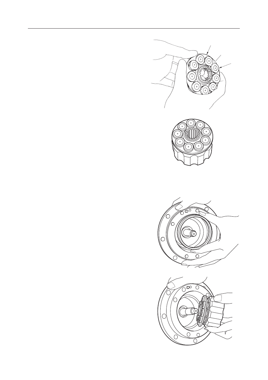
16. Mount the piston (12) and guide (13) on to the

shoe holder (11) to assemble the shoe holder
assembly.

17. Mount the shoe holder assembly on the cylinder

block to assemble the cylinder block assembly.

18. Mount the brake spacer on the flange holder.

19. Mount the cylinder block assembly on the flange

holder.
• Mount the cylinder block assembly in such a

manner that the shoe will touch the swash
plate.

C4D573

C4D574

C4D575

C4D572

11

13

12

IV-181

HYDRAULIC UNITS

TRAVEL MOTOR

TB125, 135, 145

20. Install the center discs (14) in the groove of the

flange holder and then install the friction discs
(15) in the groove of the cylinder block, alter-
nately one by one.
• Total number of center discs: 2
• Total number of friction disc: 1

21. Mount two O-rings and two backup rings on the

brake piston.
• Be sure to position the backup rings on the

outer side.

22. Mount the brake piston assembly on the flange

holder.
• Apply grease to the O-ring and be careful not

to let it bite the seal.

23. Mount the valve plate on the valve body and

insert the springs into the spring holes.
• The dot in the figure shows the spring installa-

tion positions.

• Assemble the valve plate in such a manner that

the copper surface is on the cylinder block side.

• Apply grease to the valve plate and springs,

and be careful not to drop them.

C4D577

C4D578

C4D576

14

15

G4D529

IV-182

HYDRAULIC UNITS

TRAVEL MOTOR

TB125, 135, 145

24. Supply 200 m

l

  of hydraulic oil into the flange

holder and mount the valve body on the flange
holder.

25. Fix the flange holder with a vise and tighten it

with the screws.
• Screw tightening torque:

51~65 N·m (5.2~6.6 kgf·m)

• Insert a protector such as an aluminum plate

between the flange holder and the vise to
prevent the outer surface of the body from
being damaged.

26. Install the plug.

• Seal tape should be wound around the threads

of the plug.

• Plug tightening torque:

26~31 N·m (2.7~3.2 kgf·m)

27. Mount the relief valve on the valve body.

• Relief valve tightening torque:

196~245 N·m (20~25 kgf·m)

C4D581

C4D582

G4D518

IV-183

HYDRAULIC UNITS

TRAVEL MOTOR

TB125, 135, 145

C4D583

17

18

17

C4D585

28. Mount the O-rings on the body.

29. Mount the relief valve on the motor and tighten

them with the cap screws.
• Cap screw tightening torque:

25~32 N·m (2.6~3.3 kgf·m)

Reduction Gears

1. Install the bearing (17), snap ring (18) and bear-

ing (17) in the housing.
• Be careful of the installation direction of the

bearings.

2. Fit the O-ring to the floating seal and install them

in the housing.
• Apply grease to the O-ring.

G4D519

G4D520

C4D584

IV-184

HYDRAULIC UNITS

TRAVEL MOTOR

TB125, 135, 145

3. Mount the floating seal and O-ring on the flange

holder.
• Apply grease to the O-ring.

4. Mount the housing on the flange holder and fix

them with the snap ring.
• Tighten the housing of the reduction gear and

the flange of the hydraulic motor with a C-
clamp or hydraulic press, and fix them with the
snap ring.

5. Mount the thrust washer, gear B1, needle, and

thrust washer on the pin of the flange holder and
fix them with the snap ring.
• Be careful not to expand the snap ring more

than necessary.

• The thrust washer with a larger inner diameter

should be fitted first.

6. Mount the gear S1 on the carrier and fix them with

the snap ring.

C4D586

C4D589

C4D590

C4D588

G4D521

IV-185

HYDRAULIC UNITS

TRAVEL MOTOR

TB125, 135, 145

7. Mount the thrust washer, gear B2, needle and

thrust washer on the carrier 2 and fix them with
the snap ring.

8. Mount the thrust collar on the housing.

9. Install the carrier 2 assembly in the housing.

10. Fit the O-ring to the housing.

11. Supply 0.6 L of lubricant.

C4D591

C4D595

G4D522

G4D523

IV-186

HYDRAULIC UNITS

TRAVEL MOTOR

TB125, 135, 145

12. Install the ring on the cover.

• Apply grease to secure.

13. Install the cover on the housing.

• Line up the plug holes (G 3/8) with the cuts in

the housing.

14. Fit the snap ring to secure the cover.

• Put the blade of a screwdriver on the snap ring

end and push it into position.

15. Fit the O-rings to the plugs and install the plugs on

the cover.
• Plug tightening torque:

46~51 N·m (4.7~5.2 kgf·m)

G4D524

G4D526

G4D527

G4D525

IV-187

HYDRAULIC UNITS

TRAVEL MOTOR

TB125, 135, 145

16. Fit the O-ring to the plug and install the plug on

the cover.
• Plug tightening torque:

12~13 N·m (1.2~1.3 kgf·m)

G4D528

IV-188

HYDRAULIC UNITS

TRAVEL MOTOR

TB125, 135, 145

INSPECTION AND ADJUSTMENT

“IV-165~166”

TROUBLESHOOTING

“IV-167~168”

IV-189

HYDRAULIC UNITS

TRAVEL MOTOR

TB125, 135, 145

TRAVEL MOTOR (TB145)

CONSTRUCTION

Hydraulic Motor

  1. Retainer
  2. Ball
  3. Shaft
  4. Cylinder Block
  5. Valve Plate
  6. Piston
  7. Shoe
  8. Shoe Holder
  9. Guide
10. Swash Plate

11. Pin
12. Spring
13. Retainer
14. Bearing
15. Bearing
16. 2-Speed Piston
17. Brake Piston
18. Spring
19. Snap Ring
20. O-ring

21. O-ring
22. O-ring
23. Backup Ring
24. Friction Disc
25. Center Disc
26. Oil Seal
27. Spring Pin
28. Pin
29. Backup Ring
30. Plug

IV-190

HYDRAULIC UNITS

TRAVEL MOTOR

TB125, 135, 145

  1. Housing
  2. Cover
  3. Carrier 2
  4. Gear B1
  5. Gear B2
  6. Gear S1
  7. Gear S2
  8. Pin

Reduction Gears

  9. Pin
10. Flange Holder
11. Snap Ring
12. Carrier 1
13. Needle
14. Needle
15. Floating Seal
16. O-ring

17. Bearing
18. Thrust Washer
19. Snap Ring
20. Snap Ring
21. Snap Ring
22. Ring
23. Ring
24. Pin

25. Pin
26. Plug
27. Thrust Washer
28. Plug
29. O-ring
30. Snap Ring
31. O-ring

K3D501

10

15

9

25

27

23

13

4

23

27

24

5

14

18

21

8

2

26

31

22

28

29

30

16

7

11

3

1

6 12

20

19

17

IV-191

HYDRAULIC UNITS

TRAVEL MOTOR

TB125, 135, 145

Counterbalance Valve, 2-speed Control Valve, Relief Block Assembly

1. Valve Body
2. Spool
3. Check Valve
4. Spring
5. Plug
6. O-ring
7. Spring Guide
8. Spring
9. Cap

10. O-ring
11. Orifice

12. Spool
13. Spring
14. Plug
15. O-ring
16. Plug
17. Plug
18. Orifice
19. Valve Body
20. Relief Valve Assembly
21. Relief Housing
22. Poppet

23. Seat
24. Spring Seat
25. Spring
26. Plug
27. O-ring
28. O-ring
29. Backup Ring
30. Piston
31. O-ring
32. Stopper
33. Spacer

34. O-ring
35. O-ring
36. O-ring
37. O-ring
38. O-ring
39. O-ring
40. Shuttle
41. Spacer

IV-192

HYDRAULIC UNITS

TRAVEL MOTOR

TB125, 135, 145

a1,a2

1

B1

B2

S2

S1

K3D502

OPERATION

“IV-172~175”

Reduction Gears

The reduction gear has a simple planetary two-stage
configuration. It decelerates the high speed rotary
motions of the hydraulic motor, converts them into
low speed high torque, and rotates the case. The
output shaft of the hydraulic motor is connected to the
gear S2 via the spline. The rotation of the gear S2 is
decelerated by one stage among the gears S2, B2 and
a2. This one-stage decelerated rotation is further
decelerated by two stages among the gears S1, B1 and
a1 that are connected to the carrier 2 (1) via the spline.
This rotation is conveyed to the rotary main body via
the inner gears a1 and a2 as the driving force of the
motor.

IV-193

HYDRAULIC UNITS

TRAVEL MOTOR

TB125, 135, 145

DISASSEMBLY AND ASSEMBLY

General Cautions

• Carry out disassembly and assembly operations in

a clean place and provide clean containers to place
the disassembled parts in.

• Before disassembly, clean around the ports and

remove the paint from each joint using a wire
brush.

• Wash the disassembled parts and dry them with

compressed air. Do not use a rag, as this could
cause clogging of dirt.

• Make match marks on each part so that they will be

assembled in the same positions when reassembled.

• Replace all seals with new ones each time the unit

is disassembled, coating them lightly with grease.

• Check each part to make sure there is no abnormal

wear or seizing and use sandpaper, etc. to remove
any burrs, sharp edges, etc.

The following describes the assembly procedure. For
disassembly, follow the procedure in the reverse
order referring to the construction diagram.

Assembly

Counterbalance Valve and Hydraulic Motor

1. Fix the valve body with a vise and mount the

spool on the valve body.
• To prevent the outer surface of the valve body

from being damaged, insert a protector such as
an aluminum plate between the valve body and
the vise.

• Do not disassemble the spool assembly into

parts.

2. Mount the rings (1) and springs (2) on both sides

of the spool.

3. Fit the O-ring to the plug, and tighten the plug on

both sides of the valve body.
• Plug tightening torque:

196~245 N·m (20~25 kgf·m)

C4D561

C4D562

1

2

C4D563

IV-194

HYDRAULIC UNITS

TRAVEL MOTOR

TB125, 135, 145

4. Mount the second speed spool (4) and spring (5)

on the valve body.

5. Fit the O-ring to the plug and tighten the plug to

the valve body.
• Plug tightening torque:

46~51 N·m (4.7~5.3 kgf·m)

6. Mount the shuttle on the valve body.

7. Fit the O-ring to the plug and tighten the plug to

the valve body.
• Plug tightening torque:

12~23 N·m (1.2~2.3 kgf·m)

C4D564

4

5

C4D565

IV-195

HYDRAULIC UNITS

TRAVEL MOTOR

TB125, 135, 145

8. Mount the large and small O-rings on the valve

body.

9. Press fit the oil seal into the flange holder.

• As the oil seal is to be inserted, do not disas-

semble it unless necessary.

• Fill between the lips of the oil seal with grease.

10. Fit the O-ring to the plug and install the plug on

the flange holder.
• Plug tightening torque:

12~13 N·m (1.2~1.3 kgf·m)

11. Mount the pin.

12. Mount the 2-speed piston.

K3D503

G4D516


Content      ..     30      31      32      33     ..